

Page 1
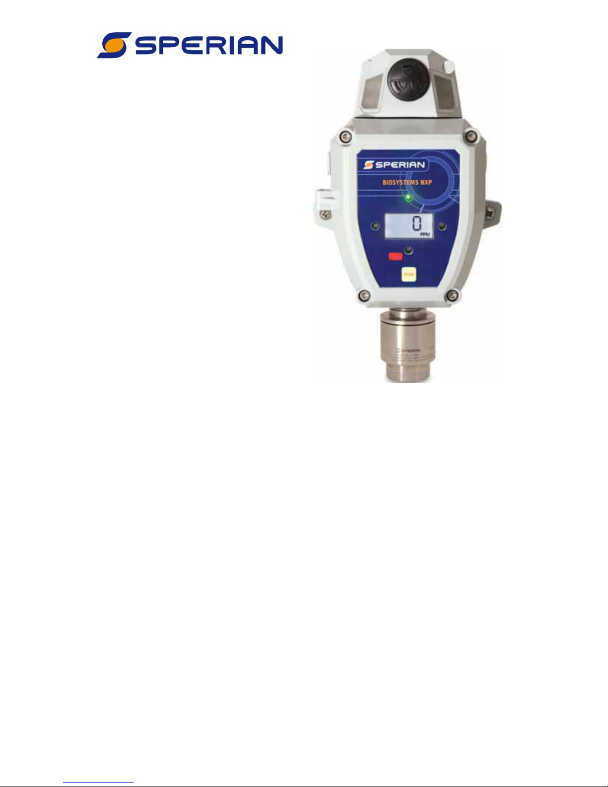
Biosystems
NXP
Fixed Gas
Detector Head
Reference
Manual
Sperian Instrumentation
651 South Main Street
Middletown, CT 06457
800-711-6776
860-344-1079
Fax 860-344-1068
Part Number 13-345
Version 1.01
10SEP2009
http://www.biosystems.com
Page 2

2
Page 3

THE BIOSYSTEMS NXP FIXED GAS DETECTOR HEAD HAS BEEN
DESIGNED FOR THE DETECTION AND MEASUREMENT OF
POTENTIALLY HAZARDOUS ATMOSPHERIC CONDITIONS.
IN ORDER TO ASSURE THAT THE USER IS PROPERLY WARNED
OF POTENTIALLY DANGEROUS ATMOSPHERIC CONDITIONS, IT
IS ESSENTIAL THAT THE INSTRUCTIONS IN THIS REFERENCE
MANUAL BE READ, FULLY UNDERSTOOD, AND FOLLOWED.
Biosystems NXP
Reference Manual
Sperian Instrumentation Part Number 13-345
Version 1.01
Copyright 2009
by
Sperian Protection Instrumentation, LLC
Middletown, Connecticut 06457
All rights reserved.
No page or part of this operation manual may be reproduced in any form without
written permission of the copyright owner shown above.
Sperian reserves the right to correct typographical errors.
Specifications are subject to change without notice.
1
Page 4

Table of Contents
Signal Words .......................................................................................................................5
Modification of Sperian Instrumentation Products ...............................................................5
Operating Temperature and Humidity Limits .......................................................................5
Warnings and Cautions .......................................................................................................6
1. Overview.......................................................................................................................7
1.1 Capabilities ..........................................................................................................7
1.2 Method of sampling..............................................................................................7
1.3 Sensor options .....................................................................................................7
1.4 Verification of accuracy........................................................................................7
1.5 Displays and controls...........................................................................................8
1.6 Power requirements.............................................................................................8
1.7 Alarms and Alarm Logic.......................................................................................8
1.7.1 Atmospheric Hazard Alarms ............................................................................8
1.7.2 Sensor Over-range Alarms ..............................................................................9
1.7.3 Alarm Relays ..................................................................................................10
1.8 Fault Conditions .................................................................................................10
1.9 Remote Sensors ................................................................................................10
1.10 4-20 mA Current Loop .......................................................................................11
1.11 Event Logger......................................................................................................11
1.12 Firmware Upgrades............................................................................................11
2. Installation ..................................................................................................................12
2.1 Installation overview...........................................................................................12
2.2 Cautions.............................................................................................................13
2.3 NXP Detector Head Environmental Ratings ......................................................13
2.4 Siting of detector heads .....................................................................................13
2.5 Wiring requirements...........................................................................................13
2.5.1 Grounding ......................................................................................................14
2.6 Output Specifications .........................................................................................14
2.7 External Wiring...................................................................................................14
2.8 Remote Sensor Installation ................................................................................16
2.8.1 Disconnecting the sensor ...............................................................................16
2.8.2 Connecting the sensor cable..........................................................................16
2.8.3 Mounting the remote sensor ..........................................................................16
2.8.4 Connecting the cable (non-explosion-proof sensor) ......................................16
2.8.5 Connecting the cable (explosion-proof sensor)..............................................16
3. Field Usage ................................................................................................................18
2
Page 5

3.1 Modes of operation ............................................................................................18
3.2 Clearing the MAX reading..................................................................................19
3.3 Effect of contaminants on NXP sensors.............................................................20
3.3.1 Effects of contaminants on oxygen sensors...................................................20
3.3.2 Effects of contaminants on combustible sensors ...........................................20
3.3.3 Effects of contaminants on toxic gas sensors ................................................20
3.4 Sensor Replacement .........................................................................................21
4. Verification of Accuracy (Calibration) .........................................................................22
4.1 Warnings and cautions concerning verification of accuracy ..............................22
4.2 Overview of verification of accuracy...................................................................22
4.2.1 Calibration Interval .........................................................................................22
4.2.2 Special Instructions for Fixed Gas Detectors .................................................22
4.2.3 Accuracy of Oxygen Sensors.........................................................................22
4.2.4 Accuracy of Toxic and LEL Sensors ..............................................................23
4.3 Fresh air calibration ...........................................................................................23
4.4 Span calibration of Toxic and LEL sensors........................................................24
4.5 Test Mode ..........................................................................................................25
4.6 Calibration Failures ............................................................................................26
4.6.1 Fresh Air Calibration Failure ..........................................................................26
4.6.2 Span Calibration Failure.................................................................................26
5. Configuration ..............................................................................................................28
5.1 Accessing the Setup menu and Submenus .......................................................28
5.2 Setup Submenu Flow Chart...............................................................................29
5.3 Set Date and Time .............................................................................................30
5.4 Set Loop Range .................................................................................................30
5.5 Set Alarm Levels................................................................................................30
5.6 Set Alarm Latch .................................................................................................31
5.7 Set Combustible Gas Sensor Display................................................................31
5.8 Set Cal Gas Concentration ................................................................................31
5.9 Set Cal Interval ..................................................................................................31
5.10 Set Bump Test Interval ......................................................................................31
6. Diagnostics .................................................................................................................32
6.1 Accessing the Diagnostics menu and Options...................................................32
6.2 Diagnostic Menu Flow Chart ..............................................................................33
6.3 Serial Number / Software Version......................................................................34
6.4 Sensor Count Display ........................................................................................34
6.5 Sensor Temperature Display .............................................................................34
3
Page 6

6.6 Current Loop Output Test ..................................................................................34
6.7 Relay Test..........................................................................................................34
6.8 12-Volt Output Test............................................................................................35
6.9 LCD and Backlight Test .....................................................................................35
6.10 LED Test ............................................................................................................35
6.11 Audible Alarm Test.............................................................................................35
7. Service........................................................................................................................36
Returning your NXP to Sperian Instrumentation for service or repair ............................36
Appendices ........................................................................................................................37
Appendix A: NXP Toxic Sensor Cross Sensitivity Data .................................................37
Appendix B: Fault Conditions.........................................................................................38
Appendix C: Calibration Frequency Recommendation ..................................................39
Appendix D: Sperian Instrumentation Warranty Gas Detection Products......................40
4
Page 7
Signal Words
The following signal words, as defined by ANSI Z535.4-1998, are used in the
NXP Reference Manual.
indicates an imminently hazardous situation which, if not
avoided, will result in death or serious injury.
indicates a potentially hazardous situation which, if not
avoided, could result in death or serious injury.
indicates a potentially hazardous situation, which if not avoided,
may result in moderate or minor injury.
CAUTION used without the safety alert symbol indicates a potentially
hazardous situation, which, if not avoided, may result in property damage.
The NXP MUST be installed in a non-hazardous area.
Modification of Sperian Instrumentation Products
Any unauthorized modification of any Sperian Instrumentation
product may compromise the certification and the safety of the product, and may
lead to serious personal injury or death. Modification of any part or component of a
Sperian Instrumentation product requires the express written approval of both the
appropriate certification agency and Sperian Instrumentation.
Operating Temperature and Humidity Limits
The Biosystems NXP’s operating temperature range is printed
on the label on the inside of the instrument. The Biosystems XPR’s operating
temperature range is printed on the housing. Use of Sperian Gas Detection
products outside of their specified operating temperature ranges may result in
inaccurate and potentially dangerous readings.
5
Page 8

Warnings and Cautions
1. The Biosystems NXP gas detector has been designed for
the detection of dangerous atmospheric conditions. An alarm condition
indicates the presence of a potentially life-threatening hazard and should be
taken very seriously.
2.
In the event of an alarm condition it is important to follow
established procedures. The safest course of action is to immediately leave the
affected area, and to return only after further testing determines that the area is
once again safe for entry. Failure to immediately leave the area may result in
serious injury or death.
3.
The accuracy of the NXP should be checked periodically
with known concentration calibration gas. Failure to check accuracy can lead to
inaccurate and potentially dangerous readings.
4.
Fresh air/zero calibrations may only be performed in an
atmosphere that is known to contain 20.9% oxygen, 0% LEL and 0 PPM toxic
gas. If fresh air is unavailable, a cylinder of “Zero Air” must be used during the
fresh air/zero calibration procedure. Calibration of the NXP in a contaminated
atmosphere may lead to inaccurate and potentially dangerous readings.
5.
The accuracy of the NXP should be checked immediately
following any known exposure to contaminants by testing with known
concentration test gas before further use. Failure to check accuracy can lead to
inaccurate and potentially dangerous readings.
6.
A sensor that cannot be calibrated or is found to be out of
tolerance should be replaced immediately. An instrument that fails calibration
may not be used until testing with known concentration test gas determines that
accuracy has been restored, and the instrument is once again fit for use.
7.
Do not reset the calibration gas concentration unless you
are using a calibration gas concentration that differs from the one that is normally
supplied by Sperian for use in calibrating the NXP. Customers are strongly urged
to use only Sperian calibration materials when calibrating the NXP. Use of nonstandard calibration gas and/or calibration kit components when calibrating the
NXP can lead to inaccurate and potentially dangerous readings and may void
the standard Sperian warranty.
Sperian offers calibration kits and long-lasting cylinders of test gas
specifically developed for easy NXP calibration. Customers are strongly urged
to use only Sperian calibration materials when calibrating the NXP.
8.
For safety reasons this equipment must be operated and
serviced by qualified personnel only. Read and understand this reference
manual before operating or servicing the NXP.
9.
A rapid up-scale reading followed by a declining or erratic
reading may indicate a hazardous combustible gas concentration that exceeds
the XPR’s zero to 100 percent LEL detection range.
6
Page 9

1. Overview
1.1 Capabilities
The NXP Gas Detector Head is a fixed
gas detection system from Sperian
Instrumentation. The NXP can function
on its own as a stand-alone unit, and can
also be used as part of a 4-20 mA current
loop system with a PLC or other type of
controller.
Standard features include user interface,
built-in digital readout to allow for direct
calibration at the head, and relays to allow
for additional alarms and control.
Each NXP Gas Detector Head includes a
sensor housing and gas-specific sensor.
Sensor housings are available in nonexplosion-proof and remote explosionproof (XPR) versions. Sensors can be
mounted directly to the NXP housing, or
can be placed remotely (up to 50 feet
away) using a special remote sensor
cable.
Note: Conduit, wire and other
components necessary to connect the
NXP Gas Detector Head to a controller
are not included and must be ordered
separately.
Installation of
explosion-proof housings must be
performed in accordance with local
regulations.
1.2 Method of sampling
The atmosphere being measured reaches
the sensor in the NXP/XPR by diffusing
through a protective filter directly into the
sensor. Normal air movements are
usually enough to carry the sample to the
sensor. The sensor reacts to changes in
the concentration of the hazard being
measured. Values are constantly updated
and displayed on the NXP Gas Detector
head’s LCD readout. If the head is
connected to a controller, the appropriate
level 4-20 mA signal is simultaneously
sent to the controller.
The NXP Gas Detector head may be
installed at a substantial distance from the
controller. The maximum distance
between the head and the controller is
2000 feet when using the proper cable.
Wiring requirements are discussed in detail
in section 2.5.
1.3 Sensor options
NXP Gas Detector Heads can be
configured to detect a number of different
atmospheric hazards. Each NXP uses a
single substance-specific sensor that
determines the hazard that the system is
configured to detect. The sensors that are
currently available, along with their ranges
and resolutions, are shown in table 1.3.
Note: Changing the sensor range will
require calibration of the instrument.
Sensor Range Resolution
Oxygen (O2)
Combustible
(LEL sensor)
Carbon
Monoxide
(CO)
Carbon
Monoxide
(CO-H)
Hydrogen
Sulfide (H
Hydrogen
Sulfide (H
Sulfur
Dioxide
(SO
)
2
0-25%/Vol.
0-30%/Vol.
0-100% LEL
0-5.0% CH
0-100 PPM
0-500 PPM
0-1000 PPM
0-100 PPM
0-500 PPM
0-1000 PPM
0-10 PPM 0.1 PPM
S)
2
0-50 PPM
0-100 PPM
S)
2
0-250 PPM
0-25 PPM
0-50 PPM
4
0.1% Vol
1% LEL
0.05% CH
1 PPM
1 PPM
1 PPM
0.1 PPM
Table 1.3 – Sensor Ranges
1.4 Verification of accuracy
NXP Gas Detector Heads have been
designed for easy verification of accuracy.
The accuracy of the NXP
should be checked periodically with
known concentration calibration gas.
Failure to check accuracy can lead to
inaccurate and potentially dangerous
readings.
Please see Sperian’s calibration
recommendations in Appendix C.
Verification of detector accuracy is a twostep procedure for toxic and LEL (XPR
only) sensor-equipped detectors, and a
one-step procedure for oxygen sensorequipped detectors.
Verification normally begins by exposing
the NXP’s sensor to known “fresh air” and
7
4
Page 10
checking the readings. If the readings
differ from those expected in fresh air
(20.9% oxygen, 0 PPM toxic gas, 0% LEL
combustible gas), a "fresh air zero"
adjustment must be made. For most fixed
applications, where the freshness of the
ambient air is in question, a cylinder of
“Zero Air” must be used during the fresh
air/zero calibration.
The second step, which only applies to
toxic and LEL sensors, is to verify sensor
accuracy by exposing it to known
concentration test gas and noting the
response. Toxic and LEL readings are
considered accurate if the readings are
between 90% and 120% of the expected
value as given on the gas cylinder. If the
reading is accurate, then the instrument
requires no further adjustment. Toxic and
LEL readings that fall outside of this range
are considered inaccurate and indicate
that the sensor must be calibrated before
further use.
Calibration procedures are discussed
in detail in Chapter 4.
1.5 Displays and controls
NXP Gas Detector Heads include a 3-digit
LCD located on the face of the detector
housing. The heads also include a MODE
button that allows the user to initiate and
control the calibration of the detector.
1.6 Power requirements
Power to the NXP can be provided either
from a controller or via a standard wall cube
available from Sperian.
The NXP requires a power supply of 13-30
VDC. Power is applied to connector J1 (see
Figure 2.5). Once powered up and running,
the NXP is intended for continuous
monitoring. If it is necessary to power down
the NXP, power should be removed from
the wall cube or controller that is supplying
power to the NXP.
1.7 Alarms and Alarm Logic
NXP Gas Detector
Heads have been designed for the
detection of dangerous atmospheric
conditions. An alarm condition
indicates the presence of a potentially
life-threatening hazard and should be
taken very seriously.
In the event of an alarm condition it is
important to follow established
procedures. The safest course of action
is to immediately leave the affected area,
and return only after further testing
together with other appropriate safety
procedures determine that the area is
once again safe for entry.
1.7.1 Atmospheric Hazard Alarms
NXP Fixed Gas Detectors with toxic or
combustible gas sensors include two levels
of alarms. One alarm serves as the
warning alarm; the second alarm serves as
the danger alarm. Detectors with oxygen
sensors have four alarm levels, as
described below.
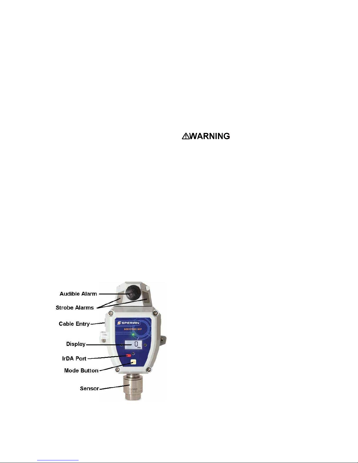
Figure 1.5 – Main NXP Components
Toxic and combustible gas sensors have
“ascending” alarms, meaning that the
alarms are activated when gas readings
rise above a pre-set alarm threshold.
Oxygen sensors have both “ascending” and
“descending” alarms, meaning that the
alarms activate when gas readings rise
above a pre-set alarm threshold or fall
below a pre-set alarm threshold. There is a
warning alarm and a danger alarm in each
direction.
Table 1.7 lists the available alarm levels
and span gas values for each sensor type.
Custom alarm levels and calibration gas
values may be set using BioTrak II
8
Page 11

software. Please see the BioTrak II
operation manual for instructions. The
alarm levels apply to both warning and
danger alarms, with the following
restrictions:
• Alarms can not be set to a value
above the full-scale range. If a range
is selected that is below current alarm
levels, the alarms will be adjusted to
default values for that range.
• The warning alarm can not be set
beyond the danger alarm setting.
Sensor
Available Alarm Levels
Type
(Process) High: OFF, 1.0, 2.0, 2.5, 5%
Oxygen (O2)
Combustible
(LEL display)
Combustible
display)
(CH
4
Carbon
monoxide
(CO, CO-H)
Hydrogen
sulfide (H
Sulfur Dioxide
(SO
S)
2
)
2
(Safety) High: 22.0, 22.5, 23.0, 23.5%
(Safety) Low: 20.0, 19.5, 19.0, 18.5, 18.0%
OFF, 0.25, 0.5, 0.75, 1.0, 1.25, 2.5% CH
OFF, 10, 25, 35, 50, 100, 150, 200 PPM
(Process) Low: OFF
OFF, 5, 10, 15, 20, 25, 50% LEL
OFF, 2, 5, 10, 15, 20 PPM
OFF, 2, 5, 10, 15, 20 PPM
Table 1.7 – Available alarm levels and calibration span gas settings
When an alarm set point is exceeded the
LEDs on the front panel and in the strobe
housing will flash (Yellow for Warning, Red
for Danger), and the audible alarm will
sound. Any external devices controlled by
means of the NXP’s alarm relay contacts
will also be activated.
Latching Alarms
NXP alarms are normally self-resetting.
When readings drop back below the preset alarm levels, the instrument returns to
normal operation, and the alarms and relay
contacts are turned off.
It is possible to set NXP’s alarms so that
they "latch". During latched operation,
once an alarm condition occurs, the visual
and audible alarms and relays will remain
active even after the atmospheric hazard
has cleared. They must be manually reset
using the MODE button. See section 5.6
for information on setting latching alarms.
Available
Span Gas
Settings
N/A
25, 30, 40, 50,
60% LEL
4
1.25, 1.5, 2.0, 2.5,
3.0% CH
35, 50, 75, 100,
150, 200 PPM
10, 20, 25, 30
PPM
10, 20, 25, 30
PPM
4
Alarm Acknowledgement
During an alarm condition, the audible
alarm and the strobe LEDs can be
acknowledged (temporarily deactivated) by
pressing the MODE button. The LEDs on
the display board and the alarm relays will
remain active. Once acknowledged, the
audible alarm and strobe LEDs will be
reactivated under the following conditions:
• Gas level remains above the alarm
level for 5 minutes
• Gas level decreases below the alarm
level, and then rises above it again
• Warning alarm was acknowledged, and
the gas level then rises above the
Danger alarm level
1.7.2 Sensor Over-range Alarms
If the concentration of the gas being
detected goes above the selected sensor
range, a sensor over-range occurs.
9
Page 12
The instrument will act as if a danger alarm
condition exists, even if the alarms have
been disabled.
• Oxygen and Toxic Gas Over-range
When the gas concentration falls back
within the sensor’s range, the over-range
alarm will be reset, unless latching alarms
have been selected.
• Combustible Gas Over-range
In the case of an LEL over-range condition
(LEL over 100%), power to the LEL sensor
will be disconnected to protect the sensor
from overheating and premature failure.
The instrument will remain in alarm with
the sensor powered down until the MODE
button is pressed or the instrument’s power
is cycled.
If the MODE button is pressed during this
time, power to the sensor will be turned on
briefly. If the gas level is below 100% LEL,
the sensor will remain on and the
instrument will resume gas detection
mode, along with any applicable alarms. If
the gas level is still over 100% LEL, the
sensor will be shut off again and the
instrument will remain in over-range alarm.
1.7.3 Alarm Relays
The NXP incorporates relays that are
activated during alarm conditions. There
are separate relays for Warning and
Danger alarms, as well as a Fault condition
relay (see section 1.8).
The Warning and Danger relays are
activated any time that the gas level
exceeds the current alarm levels. Each
relay has a normally-open and a normallyclosed contact. Normally-open contacts
close (make contact) during an alarm
condition, while normally-closed contacts
open (break contact).
These contacts can be used to operate
external alarms or larger relays that drive
other equipment, such as ventilation
systems. See Figure 2.5 for relay
connection locations.
The relay contacts in the NXP do not
supply power to the external accessories.
They act as switch contacts only. External
alarms, relays and contactors require their
own power supplies.
The maximum rating of the NXP’s relay
contacts is 30 VDC at 5 amps.
Under no
circumstances should AC line voltage
be connected directly to the relay
contacts.
1.8 Fault Conditions
The NXP is capable of detecting certain
internal fault conditions. During one of
these conditions the loop current will fall to
2 mA, the Fault relay will be activated, and
the red LEDs will flash every 5 seconds to
alert the user to the problem. Fault codes
are listed below. See Appendix B for
explanations of fault codes.
F1 - Sensor Fault
F2 – EEPROM Read Fault
F5 – EEPROM Write Fault
F11 – Power Low Fault
F12 – Power High Fault
Power Failure Fault
The Fault relay is normally energized. This
is called Fail-Safe mode. In the case of a
total loss of power to the instrument, the
Fault relay will trip, and any external
devices connected to it will be activated.
Loop current will fall to 0 mA.
Note: The Fault relay does not supply
power to the device(s) connected to it. It
acts as a switch contact only. External
power must be supplied to any devices
connected to this relay.
Under no
circumstances should AC line voltage
be connected directly to the relay
contacts.
1.9 Remote Sensors
The NXP normally comes with the sensor
housing attached to the instrument. When
necessary, the sensor can be installed
remotely, up to 50 feet from the instrument.
10
Page 13

The standard sensor can be used for nonhazardous (non-explosive) environments.
For use in hazardous locations, the XPR
explosion-proof sensor housing must be
used. The XPR is built into a heavy-duty
stainless steel explosion-proof housing. See
section 2.8 for remote sensor installation.
The XPR remote
sensor housing must not
be opened in
a hazardous location unless power to
the NXP has been disconnected. Power
must not be restored to the NXP until
the XPR housing has been completely
closed.
Installation of
explosion-proof housings must be
performed in accordance with local
regulations.
1.10 4-20 mA Current Loop
The NXP incorporates a connection for an
industry-standard 4-20 mA current loop.
This circuit generates a current based on
the gas level detected. The NXP is
normally set to “Source” mode, meaning
that it generates a current output. It can
also be set to “Sink” mode if needed,
meaning that it sinks (inputs) the current
from an external source.
A 4 mA signal indicates a reading of zero,
and a 20 mA signal indicates a full-scale
reading. Full-scale is determined by the
Loop Range setting in the Setup menu.
See Table 1.3 for available ranges and
section 5.4 for instructions on setting the
Loop Range. See Figure 2.5 for wiring of
the loop signal.
1.11 Event Logger
The event logger in the NXP stores data
associated with alarm conditions. Each
event (alarm) includes the following data:
• Event Start time
• Event End time
• Duration of the event.
• Minimum reading during event
• Maximum reading during event
• Average reading during event
• Temperature at end of event
• Sensor type
• Flags for ‘In calibration’, warning alarm,
danger alarm and temperature alarm
during event
• Time event was acknowledged
The NXP stores the data from the 128
most recent alarm events. Once 128
events have been stored, the NXP will
begin to overwrite the data from the oldest
event in memory with data from new
events. One event may be a combination
of different alarms occurring
simultaneously or in immediate
succession.
The event logger may be downloaded
using BioTrak II software. The PC must be
equipped with an IrDA port to provide a
connection.
While the NXP is
communicating through its IrDA
connection, it IS NOT
sensing the gas
level of the atmosphere, and WILL NOT
activate any alarms. The area must be
made safe or another form of
atmospheric monitoring must be used
during IrDA communication.
1.12 Firmware Upgrades
As improvements are made and features
are added to the NXP’s firmware, new
versions of the firmware will be made
available to customers. Normally, this
firmware can be downloaded and installed
by the customer using a computer with
IrDA communication capability and the
FX2 Flash Upgrade utility software.
Instrument firmware and upgrade utility
software can be downloaded from
http://www.biodownloads.com
in the
Download Section.
11
Page 14

2. Installation
2.1 Installation overview
Sperian Instrumentation’s gas detection
systems are fully tested and calibrated
before they leave the factory. Following
installation, Sperian strongly
recommends that full testing and
verification of proper operation be
carried out before the system is placed
in service.
Repair of system components damaged
as a result of improper installation can
be expensive. NXP Gas Detector Head
installation, initial setup, and/or system
modification should only be undertaken
by individuals who are qualified and
authorized to do so. Call Sperian’s
Instrument Service Department at (860)
344-1079 or 800-711-6776 if you need
help or have any questions.
Case and Mounting Dimensions (inches [mm])
Oxygen detector assemblies are available
in both standard (non-explosion-proof) and
remote explosion-proof (XPR) housings.
Toxic gas sensors are available in standard
(non-explosion-proof) housings, and certain
toxic sensors are also available in remote
explosion-proof (XPR) housings.
Remote detector assemblies for
combustible gas are only available in
explosion-proof (XPR) housings.
NXP Gas Detector Heads are equipped to
provide a 4-20 mA output that is used to
communicate with a remotely located
controller or PLC system. Each detector
head also has a built-in LCD readout for
local display of gas type and concentration.
When used in this type of configuration,
power is supplied to the detector by the
controller.
When used as a stand-alone detector,
power can be supplied to the detector
from a standard wall cube that is included
with the detector, or from an external
power supply with an output of 13-30
12
Page 15

VDC. In this configuration, the NXP must
be set to Source mode (see Figure 2.5).
ducts in which gases that are heavier than
air may collect.
2.2 Cautions
The NXP MUST be
installed in a non-hazardous area. Only
the XPR explosion-proof sensor
housing, if used, may be installed in a
hazardous location.
Disconnect the NXP Gas Detector Head
from any external power source and
from any battery backup power supply
before installing, replacing, or handling
system components.
Both the Gas Detector head and any
connected controller unit should be
calibrated and alarm levels tested at
the time of initial installation before the
system is first put into service.
2.3 NXP Detector Head
Environmental Ratings
The NXP housing has an environmental
rating of NEMA 4X and an ingress
protection rating of IP66. These ratings
apply to the NXP only, and do not extend
to the wall cube power supply. If the NXP
is to be installed in an area where it could
be exposed to pressurized jets of water,
wind-blown sand or dust, or other adverse
environmental conditions, it is
recommended that power be connected
through weather-proof cabling or conduit.
See section 2.7 for instructions on
removing the wall cube and connecting
external wiring.
2.4 Siting of detector heads
The specific placement of gas detector
heads should be determined by the type
of area being monitored, the type and
source of the atmospheric hazard being
measured, prevailing wind patterns, and
other information.
Call Biosystems Technical Service
Department at (860) 344-1079 or 800711-6776 for additional advice.
In general, for gases lighter than air the
detector heads should be placed at a level
slightly above the area where leaks are
likely to occur. For gases that are heavier
than air the detectors should be located
close to floor level or in inspection pits or
There are many circumstances that may
modify this general advice. It is beyond
the scope of this manual to attempt to
describe all of the potential situations that
could cause this advice to be modified,
but a single example follows:
The molecular weight of nitrogen (MW ≅
28) is very close to that of air (MW ≅ 29).
When nitrogen is at the same temperature
as the air into which it is introduced, it
mixes readily, and tends to spread evenly
throughout the affected atmosphere. On
the other hand, if the nitrogen is under
pressure, and then suddenly released into
the atmosphere, as the gas expands
(going from higher pressure to a lower
pressure) it cools. The cooler gas is
denser than the air into which it is being
introduced, so it no longer mixes as
readily. Instead, the nitrogen tends to sink
to floor level and spread laterally. In this
case remote detectors being used to
monitor for oxygen deficiency should be
located near floor level in order to detect
the deficiency as quickly as possible.
The nearer in density to air a gas is, the
more easily it will flow with air due to
drafts, ventilation etc. A compromise
approach for placement of detectors used
to measure gases which are only slighter
lighter (such as carbon monoxide) or
heavier (such as hydrogen sulfide) than
air is to mount the detectors at a height as
close as possible to the breathing area of
personnel being protected.
When installing detector heads it is
important to ensure that the sensor is not
exposed to liquid or dust contamination
that would interfere with the passage of
gas through the protective filter into the
sensor. Detector assemblies should be
placed so that the sensor points straight
downward. A splash deflector should be
used when water or other liquids are
chronically present in the area where the
detector is located.
2.5 Wiring requirements
Recommendations for wire used to
connect NXP detector assemblies to a
standard controller unit with a 24 VDC
power supply are listed in Table 2.5.
13
Page 16

Lower power supply voltages may require
larger size wire.
scale reading (100% LEL or a full-scale
oxygen or toxic gas reading).
Conductor
Size (AWG)
22 3 500
20 3 800
18 3 1200
16 3 2000
Number of
Conductors
Maximum
length (ft)
Table 2.5 NXP system wiring
recommendations
“Maximum length” indicates the maximum
distance a detector head may be located
from the controller when using the
indicated gauge of conductor. For all
types of detector assemblies, use 3conductor shielded cable with drain.
Due to the relatively low signal levels
carried by wiring between gas detectors
and the control unit, it is essential not to
run wire near high power electrical
equipment. When NXP heads are
installed in environments that contain high
power electrical equipment it is usually
best to install the wire in conduit.
The NXP wiring diagram is given below in
figure 2.5.
Remote Sensor Cable
The sensor can be placed remotely up to
50 feet away from the NXP (See section
2.8). Cable for connecting a remote
sensor to the NXP must be specified
when placing the order.
2.5.1 Grounding
Cable used to connect NXP gas detector
heads to a controller should always have
a shield and drain lead. In order to reduce
electromagnetic interference (EMI), the
screen (drain) of the cable should be
connected to the ground connection of the
detector head. Ground loops must be
avoided. Grounding is done through the
normal safety earth of the system.
2.6 Output Specifications
When the NXP is used with a controller,
the controller should be configured to
respond to an industry-standard 4-20 mA
current loop signal, with 4 mA indicating a
reading of zero (0% LEL, 0% O
or 0 PPM
2
toxic gas), and 20 mA indicating a full-
The NXP is shipped in Source Mode,
meaning it acts as the source of the loop
current. It can be switched to Sink Mode if
necessary by moving the jumper from J10
to J9 on the communication board, and
connecting the signal wire to pin 2 instead
of pin 3 on J1 (see Figure 2.5).
When used as a stand-alone instrument,
whether powered by a wall cube or
external power supply, the NXP must be
in Source mode.
2.7 External Wiring
The NXP is shipped with a wall cube
attached for ease of installation. In some
cases it may be desirable to use external
wiring instead, such as when connecting
the NXP to a controller or other power
supply, or when it is to be mounted in an
area where it could be exposed to water,
dust, or other harsh environments. To
install external wiring, follow the
instructions below.
1. Make sure that there is no power
applied to the NXP. Unscrew the four
screws on the cover. Pull the cover
straight out, and then swing it to the left.
2. Grasp the electronics assembly and
carefully pull it straight out from the
housing, being careful not to pull on the
attached wiring.
3. Unplug the 4-pin connector that is
plugged into J1 on the rear PCB. Using a
small screwdriver, loosen the wire contact
screws on the connector and remove the
wires.
4. Pull the wall cube wires out through the
back of the unit. From inside the housing,
screw the supplied #8 self-tapping screw
(with washer) into the hole where the wall
cube wires were removed.
5. Remove one of the plastic plugs from
either side of the housing. Depending on
the desired wiring, install either a 1/2”
NPT cable strain relief or a 1/2” NPT
conduit fitting, using Teflon tape on the
threads. Tighten firmly but do not
overtighten.
6. Route the wiring through the strain
relief or fitting and connect the wires to the
14
Page 17

connector. Refer to Figure 2.5 for the
correct connections.
7. Plug the connector into J1 on the PCB.
Reinstall the electronics assembly and
push until it is fully seated against the
standoffs to which it mounts.
8. Apply power to the NXP and ensure
correct operation. Make sure the cover
gasket is seated, close the cover and
tighten the cover screws securely.
Figure 2.5 NXP detector wiring diagram
15
Page 18

2.8 Remote Sensor Installation
The NXP normally comes with the sensor
housing attached to the instrument. When
necessary, the sensor can be installed
remotely, up to 50 feet from the instrument.
Follow the procedure below to connect the
sensor using a separately supplied remote
connector cable. Cables are available in
lengths of 5, 10 and 50 feet.
2.8.1 Disconnecting the sensor
Be sure that power is
removed from the NXP.
Unscrew the four cover screws on the
front of the NXP housing, then pull the
cover slightly away from the housing and
swing it open.
Grip the circular electronics assembly and
gently pull the assembly from its mounting
points. Disconnect the sensor cable from
the PCB connector.
Using a 1-1/8” wrench on the flat surfaces
just below the threads, unscrew the entire
sensor housing from the instrument
housing. There is no need to remove the
sensor housing cover.
2.8.2 Connecting the sensor cable
Apply Teflon sealing tape to the threads of
the metal thread adapter and install it in
the hole where the sensor housing was
removed. Tighten snugly, but do not
overtighten.
Apply Teflon sealing tape to the threads of
the strain relief, which can now be
installed into the metal thread adapter or
into one of the other ports near the top of
the unit. Close off any unused ports
(including the thread adapter, if not used)
with the plugs provided in order to
maintain the environmental integrity of the
enclosure.
Insert the female end of the sensor cable
into the strain relief outer nut, making sure
that the internal rubber grommet is in
place. Push several inches of the cable
into the instrument housing. Do not tighten
the nut yet.
Connect the cable to the PCB connector
where the sensor cable was removed. Be
sure to observe the correct polarity when
connecting the cable. When it is
connected, replace the electronics
assembly in the housing, pushing firmly
so that it seats on its mounting points.
Make sure that there are a few inches of
slack in the cable inside the housing, and
then tighten the strain relief nut until the
cable is grasped firmly.
2.8.3 Mounting the remote sensor
Thread the sensor housing into the
sensor connection box supplied with the
remote cable kit and tighten securely.
Mount the box in the chosen location with
the sensor housing facing downward.
Mounting the sensor in any other
orientation could allow water or debris to
collect on the sensor face, impairing
operation.
For explosionproof sensors in hazardous locations,
conduit is required from the sensor
connection box to the safe area. Check
local electrical requirements for proper
conduit and conduit seals.
2.8.4 Connecting the cable (non-
explosion-proof sensor)
Route the cable through any necessary
wire trays, conduit, etc., to the location of
the remote sensor. If using conduit,
remove the strain relief from the
connection box and connect the conduit
to the box. Otherwise, run the male end of
the cable through the strain relief and into
the box, using the procedure outlined in
section 2.8.2. See figure 2.8 for an
exploded view of the assembly.
Connect the cable to the sensor
connector, observing the polarity of the
connectors. Provide some slack inside
the box, and then tighten the strain relief
nut until the cable is grasped firmly.
Install the connection box cover, apply
power to the instrument and check for
proper operation.
2.8.5 Connecting the cable
(explosion-proof sensor)
For explosionproof sensors in hazardous locations,
16
Page 19

explosion-proof conduit is required
from the sensor connection box to the
safe area. Check local electrical
requirements for proper conduit and
conduit seals.
Route the cable through the conduit to the
location of the remote sensor.
Inside the sensor connection box, connect
the cable to the sensor connector,
observing the polarity of the connectors.
Close the connection box and tighten the
cover securely. Make sure any required
conduit seals are in place.
Apply power to the instrument and check
for proper operation.
Figure 2.8 Non-explosion-proof
remote sensor assembly
17
Page 20

3. Field Usage
Once the NXP has been installed and
connected to a power source, it will run
through a boot-up process, and then be in
continuous operation. During the boot-up
process, the following information will be
shown on the display:
• Power supply voltage
• LCD Test (All Segments On)
• Firmware Version
• “NEP” (Indicates Non-Explosion-
Proof Instrument)
3.1 Modes of operation
Press the MODE button to scroll through
the screens. The current gas reading
screen is shown during normal operation.
Detector heads equipped with toxic gas
sensors will display gas readings in partsper-million (PPM). Some sensors will
resolve readings to tenths of a part per
million.
• Sensor Type
• Loop Range (See Section 5.4)
• Instrument Serial Number
• Warning and Danger Alarm Levels
• Calibration reminder (if set)
• Bump Test reminder (if set)
• 10-second countdown
Gas readings are shown on the display on
the front of the detector. Toxic gas
readings are normally displayed in partsper-million (PPM), oxygen readings are
given in terms of percent volume (%Vol),
and combustible gas readings are given in
either percent LEL (LEL), or percent
volume methane (CH
).
4
Detector heads equipped with oxygen
sensors display readings in percent-byvolume. Fresh air contains 20.9% oxygen
by volume.
Detector heads equipped with
combustible gas sensors can display
readings in terms of either percentage of
the Lower Explosive Limit (%LEL) or
percent methane by volume (%CH4).
A reading of 100%
LEL or 5% CH4 indicates a potentially
explosive environment.
From the current gas readings screen,
press the MODE button once to view the
MAX reading screen. The MAX readings
screen displays the highest reading that
has been recorded by the instrument in
the past 24 hours.
18
Page 21

If the Calibration Interval has been set,
pressing the MODE button again within 8
seconds will display the number of days
until calibration is due.
↓
↓
↕
In addition, every 30 seconds the “CAL
dUE” reminder will appear on the display
and the red LEDs will flash.
↓
Similarly, if the Bump Interval has been
set, pressing the MODE button again
within 8 seconds will display the number
of days until a bump test is due.
See chapter 4 for instructions on
verifying sensor accuracy.
3.1.1 Calibration Due Warnings
When the NXP is due for calibration, the
triangular warning symbol is shown in the
current gas readings screen and the
calibration icon and green LED will blink.
3.2 Clearing the MAX reading
If it becomes necessary to clear the MAX
reading, press and hold the MODE button
for 4 seconds. The “MAX CLr” screen will
appear. Release the button within 4
seconds and a countdown will start. Press
the MODE button during the countdown
to reset the MAX reading to zero.
19
Page 22

3.3 Effect of contaminants on NXP
sensors
The atmosphere in which the NXP gas
detector head is located can have a
lasting effect on sensor accuracy.
Sensors may be poisoned or suffer
degraded performance if exposed to
certain substances.
There are three basic types of sensors
that may be installed in NXP detector
assemblies; galvanic oxygen, catalytic
hot-bead combustible gas (LEL), and
electrochemical toxic. Each type of
sensor uses a slightly different detection
principle, so the conditions that affect the
accuracy of the sensors vary from one
type of sensor to the next.
The accuracy of the
NXP should be checked immediately
following any known exposure to
contaminants by testing sensor
response with known concentration
test gas before further use. Failure to
check accuracy after a known sensor
exposure can lead to inaccurate and
potentially dangerous readings.
3.3.1 Effects of contaminants on
oxygen sensors
Oxygen sensors may be affected by
prolonged exposure to "acid" gases such
as carbon dioxide. The oxygen sensors
used in Sperian instruments are not
recommended for use in atmospheres
which continuously contain more than
25% CO
.
2
3.3.2 Effects of contaminants on
combustible sensors
Combustible sensors may be affected by
exposure to substances containing
silicone. For a complete list of known LEL
sensor contaminants, see the sensor
section of the Sperian Standard Warranty
in Appendix D.
Note: If sensitivity of the combustible
sensor is lost due to poisoning, it
tends to be lost first with regards to
methane.
A partially poisoned LEL sensor might still
respond accurately to propane while
showing a dangerously reduced response
to methane.
Sperian’s “Propane Equivalent”
calibration gas mixtures have been
developed to eliminate this potentially
dangerous source of calibration error.
Sperian’s “Propane Equivalent” mixtures
are based on methane so any loss of
sensitivity to methane is detected (and
can be corrected) immediately.
The combustible
sensor used in the NXP/XPR requires a
minimum of 10% oxygen by volume in
order to generate accurate
combustible gas readings.
Combustible sensor accuracy may be
diminished if the instrument is used in
oxygen-deficient atmospheres.
A rapid up-scale
reading may indicate a hazardous
combustible gas concentration that
exceeds the NXP’s detection range.
3.3.3 Effects of contaminants on
toxic gas sensors
Sperian uses “substance-specific”
electrochemical sensors that have been
carefully designed to minimize the effects
of common interfering gases.
“Substance-specific” sensors are
designed to respond only to the gases
that they are intended to measure. The
higher the specificity of the sensor the
less likely the sensor will be affected by
exposure to other gases which may also
be present. For instance, a “substancespecific” carbon monoxide sensor is
deliberately designed not to respond to
other gases that may be present at the
same time, such as hydrogen sulfide and
methane.
Even though care has been taken to
reduce cross-sensitivity, some interfering
gases may still have an effect on toxic
sensor readings. In some cases the
interfering effect may be “positive” and
result in readings that are higher than
actual. In other cases the interference
may be negative and result in readings
that are lower than actual.
20
Page 23

Cross sensitivity figures for toxic
sensors and common interfering gases
are listed in Appendix A.
3.4 Sensor Replacement
The sensor in the NXP is located inside
the sensor housing located on the bottom
of the instrument (see figure 1.5), or at the
remote sensor location.
If a remote XPR
(explosion-proof) sensor housing is
being used with the NXP, do not open
any part of the XPR’s housing in a
hazardous location unless power to the
NXP has been disconnected. Power
must not be restored to the NXP until
the XPR housing has been completely
closed.
To replace a sensor:
1. Remove power to the NXP.
Once the stabilization period has passed,
perform the Fresh Air Zero and the Gas
Calibration procedures as discussed in
sections 4.3 and 4.4.
2. Loosen the setscrew on the cover of
the sensor housing. Unscrew and remove
the cover.
3. Remove the metal collar around the
sensor by pulling it straight out of the
housing (do not twist). If the sensor did
not come out with the collar, remove it
separately.
4. Notice the small hole on the end
surface of the collar. Re-insert the collar,
lining up the hole with the pin on the
sensor adapter board. Make sure the
collar is fully inserted.
5. Line up the key on the new sensor with
the slot in the collar and push the sensor
into the collar until it mates with the
connector on the adapter board.
6. Install the sensor cover and screw it on
until it is fully seated against the sensor
housing base. Re-tighten the setscrew.
7. Apply power to the NXP. New sensors
must be allowed to stabilize prior to use,
according to the following schedule.
Sensor Stabilization
Period
Oxygen (O2) 1 hour
LEL 5 minutes
Toxic Sensors 15 minutes
21
Page 24

4. Verification of
Accuracy (Calibration)
4.1 Warnings and cautions concerning
verification of accuracy
The accuracy of the
NXP should be checked immediately
following any known exposure to
contaminants by testing with known
concentration test gas before further
use. Failure to check accuracy after a
known sensor exposure can lead to
inaccurate and potentially dangerous
readings.
A sensor that cannot
be calibrated or is found to be out of
tolerance should be replaced
immediately. An instrument that fails
calibration may not be used until
testing with known concentration test
gas determines that accuracy has been
restored, and the instrument is once
again fit for use.
Use of non-standard
calibration materials may lead to
dangerous error and may void
Biosystems standard warranty for gas
detection products. Customers are
strongly urged to use only Biosystems
calibration materials when calibrating
the NXP detector.
For detector heads that are used as part
of a detection system with a controller, it
is necessary to calibrate both the
controller and the gas detector head
when the system is first put into use.
Once the system has been properly
calibrated, the accuracy of the gas
detector head should be regularly verified
by exposure of the sensor to known
concentration test gas.
4.2.1 Calibration Interval
A regular schedule for ongoing
verification of gas detector head accuracy
should be set up. See Appendix C for
Sperian’s position on calibration
frequency.
The NXP has the ability to alert the user
when calibration is required. See section
5 for instructions regarding setting the
Calibration Interval.
When the calibration interval is reached,
the instrument will alert the user by
flashing “CAL dUE” and the gas bottle
icon on the display once every 30
seconds. The red alarm LEDs will also
flash.
→
The accuracy of
the NXP should be checked
periodically with known concentration
calibration gas. Failure to check
accuracy can lead to inaccurate and
potentially dangerous readings. See
Appendix C for Sperian’s position on
calibration frequency.
4.2 Overview of verification of
accuracy
NXP Gas Detector Heads have been
designed for easy single-person
calibration. The MODE button is located
on the display board and is used to enter
the Calibration and Test modes. The LCD
readout provides ongoing readings and
messages at the detector head during
calibrations and bump tests.
4.2.2 Special Instructions for Fixed
Gas Detectors
Fixed detectors are commonly located in
environments in which the purity of the
ambient air is unknown. In this case, a
cylinder of “Zero Air”, which contains
20.9% oxygen and no contaminants, must
be used to verify that the detector is
displaying the correct readings for a fresh
air atmosphere, and to perform a fresh air
calibration when necessary. “Zero Air” is
available from Sperian.
A second cylinder of gas is also required
for instruments equipped with toxic and
combustible gas sensors, so it is not
unusual to use two cylinders of calibration
gas to calibrate a fixed gas detector.
4.2.3 Accuracy of Oxygen Sensors
Oxygen detectors should read 20.9% in a
fresh air environment.
22
Page 25

If the oxygen detector is reading anything
except 20.9% when exposed to fresh air,
it should be fresh air calibrated as
discussed in section 4.3.
As discussed in section 4.2.2, a cylinder
of “Zero Air” must be used during the
fresh air calibration if there is any reason
to question the purity or composition of
the ambient atmosphere.
If a cylinder of “Zero Air” is to be used to
provide the fresh air source during the
fresh air calibration, connect the cylinder
to the detector and flow gas to the sensor
for 30 seconds before beginning this
procedure.
To initiate the fresh air calibration, press
the MODE button three times quickly in
succession.
4.2.4 Accuracy of Toxic and LEL
Sensors
In a fresh air environment, toxic gas
detectors should read 0 PPM and LEL
detectors should read 0% LEL.
If the toxic or LEL detector reads anything
other than zero when exposed to a known
source of fresh air, it should be fresh air
calibrated as discussed in section 4.3.
As discussed in section 4.2.2, a cylinder
of “Zero Air” must be used during the
fresh air calibration if there is any reason
to question the purity or composition of
the ambient atmosphere.
The second step (for toxic and LEL
sensors only) is to expose the sensor to
known concentration test gas and note the
sensor response. To test sensor
response in the NXP, place the detector in
Test Mode as discussed in section 4.5
and apply calibration gas.
During the sensor response test, toxic and
LEL readings are considered accurate if
the readings are between 90% and 120%
of the expected value as given on the gas
cylinder. If readings are accurate, then
the instrument requires no further
adjustment. Toxic and LEL readings that
do not fall between 90% and 120% of the
value on the cylinder are considered
inaccurate and indicate that the sensor
must be calibrated before further use as
discussed in sections 4.3 and 4.4.
4.3 Fresh air calibration
As discussed in section 4.2.2, fixed
systems are often used in locations where
the ambient air may not be fresh. In these
situations it is necessary to use a cylinder
of “Zero Air” to provide a known source of
contaminant-free air with 20.9% oxygen
for the fresh air calibration.
The detector head will show “CAL” with
the triangular warning symbol and
proceed to a 5-second countdown. The
triangular warning symbol is lit in this
case to let the user know that the gas
alarms will be disabled for the duration of
the fresh air calibration procedure.
↓
Press the MODE button prior to the end
of the countdown to initiate the fresh air
calibration. The screen will show
alternating left and right zeroes during the
process with the warning icon lit to show
that the alarms are disabled.
↕
23
Page 26

Following successful zero calibration,
NXP detectors with toxic or combustible
gas sensors will proceed to the span
calibration routine and will begin another
5-second countdown with the calibration
bottle icon lit.
To conclude the fresh air calibration
without performing a span calibration,
allow the countdown to reach zero without
pressing the MODE button. The NXP will
then return to the current gas reading
screen.
Connect the cylinder with the span
calibration gas to the detector and flow
gas to the sensor.
Customers are
strongly urged to use only Sperian
calibration materials when calibrating
the NXP. Use of non-standard
calibration gas and/or calibration kit
components when calibrating the NXP
can lead to inaccurate and potentially
dangerous readings and may void the
standard Sperian warranty.
4.4 Span calibration of Toxic and
LEL sensors
To initiate the span calibration routine for
toxic and LEL sensors, first complete the
fresh air calibration as detailed in section
4.3. A second 5-second countdown will
begin. The calibration cylinder icon will be
lit to let the user know that this countdown
is for the span calibration routine.
Press the MODE button before the
countdown concludes to initiate the span
calibration. If a cylinder of “Zero Air” was
used to provide fresh air during the fresh
air calibration, the cylinder should be
disconnected from the detector now.
The screen will alternate between GAS
and the expected calibration gas level.
The expected
calibration gas values should match the
applied gas values from the calibration
tank. Failure to ensure that these
numbers match can lead to inaccurate
and potentially dangerous readings
which could result in serious injury or
death.
Sperian Instrumentation offers calibration
kits and long-lasting cylinders of test gas
specifically developed for easy NXP
calibration.
Once gas is detected, the current reading
is shown with the bottle icon to show that
the detector is in calibration mode.
Once the instrument successfully
completes the span calibration, it will
display the maximum span calibration
adjustment value for two seconds. The
calibration gas should be removed at this
time.
↕
Following the Max Span screen the
instrument will continue to show the
current gas reading without the alarms in
order to allow the readings to drop back
below alarm levels. The triangular
24
Page 27

warning symbol will remain on to remind
the user that alarms are currently
disabled.
Once the readings drop below the alarm
level threshold the detector will return to
normal operation. However, alarms will be
enabled again in 60 seconds regardless of
the gas level.
↓
The span calibration mode can be
canceled at any time by pressing the
MODE button. If the sensor has not
detected the presence of calibration gas,
the detector returns immediately to normal
operation. If calibration gas was detected,
the “alarms off” settling time described
above will occur.
4.5 Test Mode
The Test Mode is used to verify accuracy
without performing a full calibration. This
type of test is commonly referred to as a
bump test. While the instrument is in Test
Mode, it will not go into alarm despite the
fact that the instrument may detect levels
of gas that exceed the alarm threshold.
For detectors that are used with a
controller, during Test Mode the detector
will send a signal to the controller that
mimics a fresh air reading to keep the
controller from registering an alarm
condition.
While in test mode, the green and yellow
LEDs will blink once every 10 seconds to
remind the user that alarms have been
disabled.
Allow the countdown to reach zero. The
test countdown will then be shown.
↓
Press MODE before the end of the
countdown to enter Test Mode. The
screen will alternate between “tSt” and
the gas reading for the duration of the
test.
To enter the Test Mode, press the MODE
button three times quickly in succession
as if to enter the Fresh Air Calibration
routine. The screen will show CAL and
begin a 5-second countdown.
↕
25
Page 28
Apply a known concentration calibration
gas to the sensor. Toxic and LEL readings
are considered accurate if the readings
are between 90% and 120% of the
expected value as given on the gas
cylinder. If readings are accurate, then
the instrument requires no further
adjustment. Toxic and LEL readings that
do not fall between 90% and 120% of the
value on the cylinder are considered
inaccurate and indicate that the sensor
must be calibrated before further use as
discussed in sections 4.3 and 4.4.
Customers are
strongly urged to use only Sperian
calibration materials when calibrating
the NXP. Use of non-standard
calibration gas and/or calibration kit
components when calibrating the NXP
can lead to inaccurate and potentially
dangerous readings and may void the
standard Sperian warranty.
be lit to show that the alarms are off until
the readings fall below the alarm levels.
The instrument will automatically exit Test
Mode if the MODE button is not pressed
within 5 minutes.
4.6 Calibration Failures
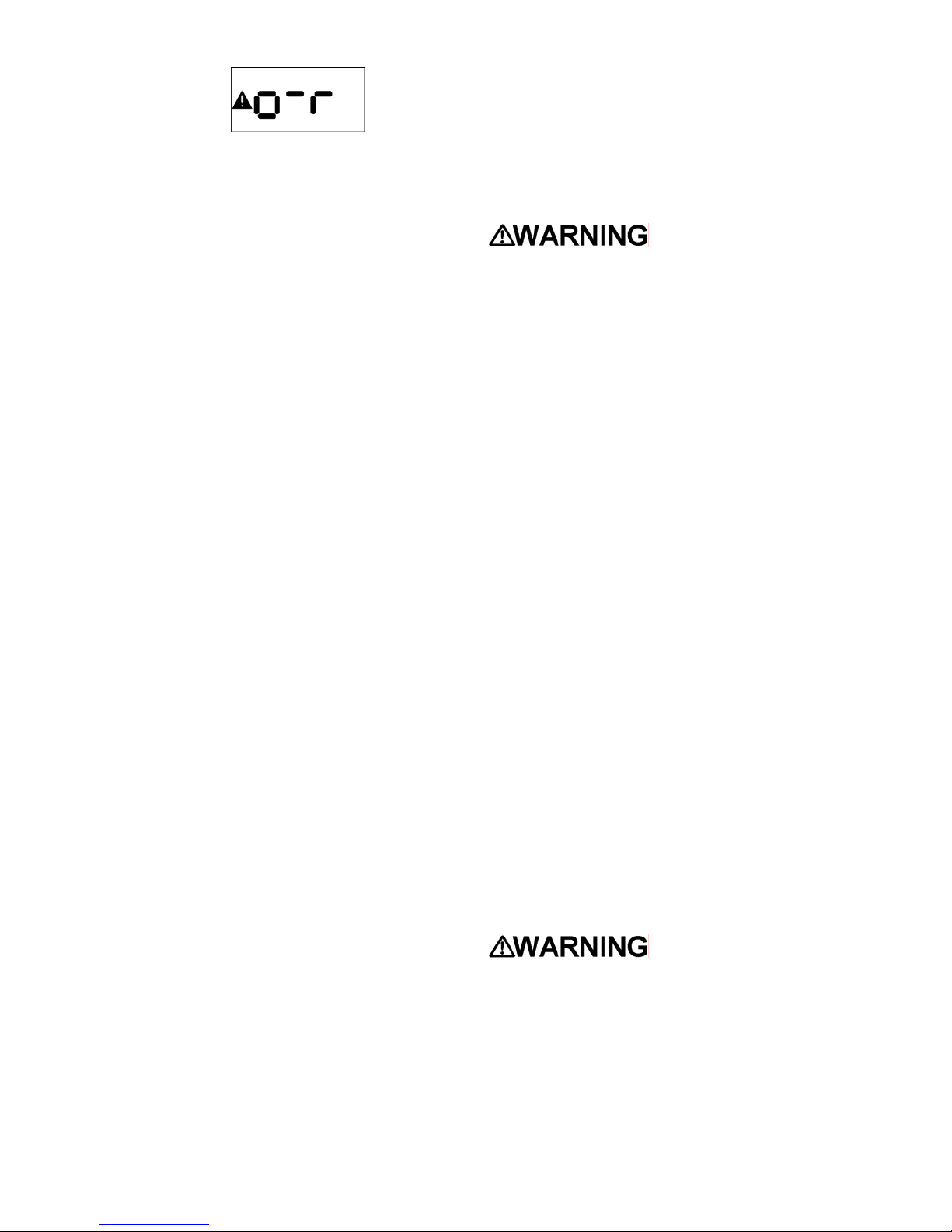
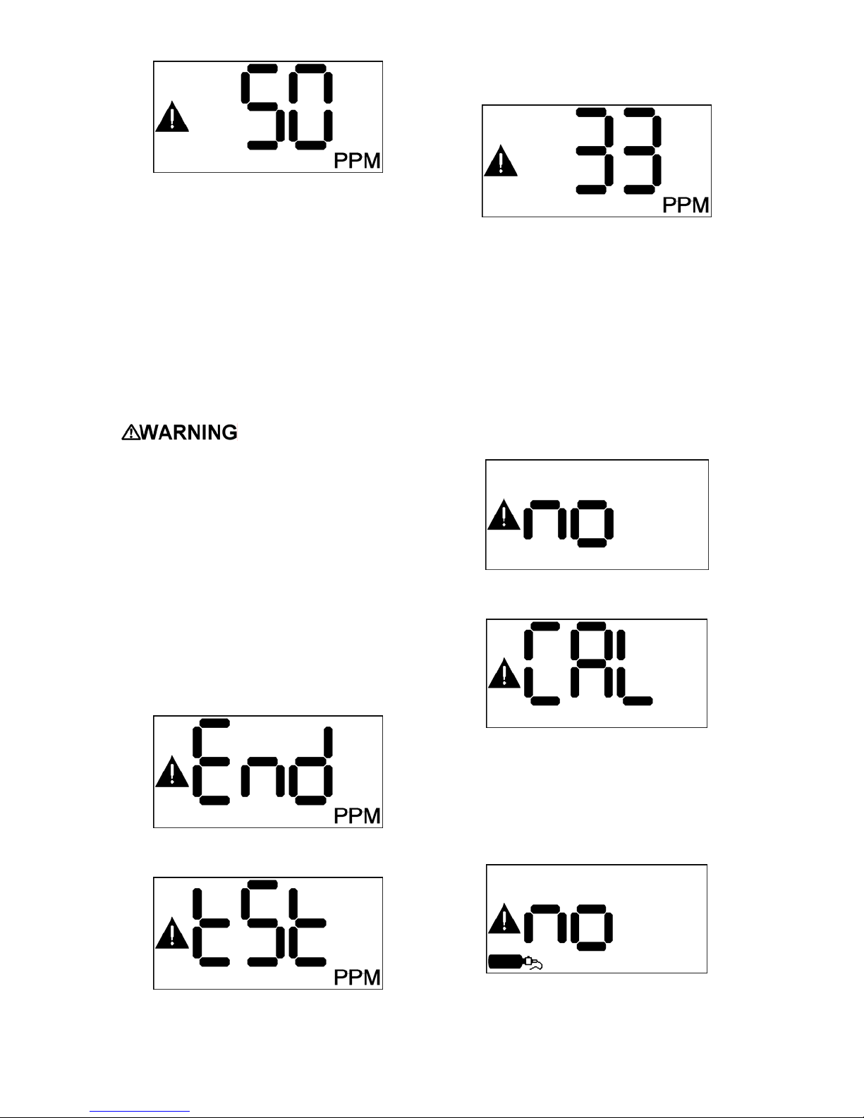
4.6.1 Fresh Air Calibration Failure
If the NXP is unable to complete the fresh
air calibration, the instrument will show
“no CAL” and then the countdown for Test
Mode before returning to the current gas
reading screen.
Sperian Instrumentation offers calibration
kits and long-lasting cylinders of test gas
specifically developed for easy NXP
calibration.
Press MODE to end the test and resume
normal gas reading mode.
↓
The detector will then return to the current
gas reading screen. The warning icon will
↕
4.6.2 Span Calibration Failure
If the NXP is unable to complete the span
calibration, the instrument will show “no
CAL” with the calibration cylinder icon
before returning to the current gas
reading screen.
↕
26
Page 29

If the NXP is unable to complete the span
calibration because it completely fails to
detect gas, it will show “no GAS” before
returning to the current gas reading
screen.
↕
5. LEL only: Wrong type of combustible
calibration gas. LEL calibration gas may
be based on several different response
standards; methane, propane and
pentane are the most common. If using a
new cylinder of calibration gas, make sure
that the type and concentration of
combustible gas is identical to that of the
previous bottle. Sperian Instrumentation
offers calibration gases in Methane,
Propane Equivalent and Pentane
Equivalent.
6. Inoperative sensor. Contact Sperian
Instrumentation for a replacement sensor.
7. Instrument problem. Contact Sperian
Instrumentation’s Instrument Service
department at the phone number on the
front of this manual.
Possible causes of span calibration
failure and remedies:
1. Empty calibration gas cylinder. Verify
that there is calibration gas in the cylinder.
2. Expired calibration gas cylinder. Verify
that the expiration date on the cylinder
has not passed.
3. Calibration equipment not connected
correctly. Check all connections between
cylinder, regulator, tubing, calibration
adapter and sensor.
4. Calibration gas setting does not
correspond to calibration gas
concentration. The default calibration gas
concentration is stored in the instrument’s
memory. If the value on the calibration
cylinder is different from the instrument’s
calibration gas setting, the calibration gas
setting must be changed to match the new
value, or the correct value calibration gas
must be obtained. Calibration gas value
can be changed by accessing the setup
menu with the MODE button as discussed
in section 5.
27
Page 30

5. Configuration
The following section explains how to set
up the NXP using the setup menu and
MODE button. All of the features in the
setup menu are also available through
IrDA communication using Sperian’s
BioTrak II software. Please see the
BioTrak II manual for instructions.
The NXP includes a setup menu that
allows the user to set up various
parameters and functions. The menu is
accessed though the MODE button.
5.1 Accessing the Setup menu and
Submenus
To access the Setup Menu, press and
hold the MODE button. The current gas
reading screen will be replaced with the
MAX Clr screen after about 3 seconds.
Continue to hold the button. In a few more
seconds, “SEt” will be shown.
The Setup menu and all of the submenus
are on a 5-second clock. To enter one of
the submenus, press the MODE button
while the submenu item is shown. To skip
over a submenu, do nothing. Once 5
seconds have passed the NXP will
automatically move to the next submenu.
This will continue until the final submenu
is reached. At the end of the 5-second
countdown for the final submenu, if the
MODE button is not pressed, the NXP will
return to the current gas reading screen.
The operating logic in the submenus is the
same as the operating logic in the main
menu. In each of the submenus, press
the MODE button to go deeper into the
submenu, or to make changes. Do
nothing to move on to the next submenu
item without making changes. Once the
final item in a submenu is reached, the
NXP will return to the next higher
submenu.
Release the MODE button. “UP” will be
shown, then a 5-second countdown will
start. To enter the setup menu, press the
MODE button before the countdown
reaches zero. To return to the gas
reading screen, do nothing. Once 5
seconds have passed, the NXP will
display the current gas reading.
Once in the setup menu, the NXP will
display “Set dAt”.
↔
The instrument will automatically scroll
through all of the menu choices. See the
flow chart in section 5.2 for details.
28
Page 31

5.2 Setup Submenu Flow Chart
Depending on the installed sensor, some of the following menu choices may be
unavailable. See individual sections for more information.
= Back to gas reading
+ = Enter Setup Menu
+ = Set Date, Time (see 5.3)
+ = Set Loop Range (see 5.4)
+ =
Set Alarm Levels (see 5.5)
+ = Set Alarm Latch (see 5.6)
+ = Set Combustible Sensor Display (see 5.7)
+ = Set Calibration Gas Level (see 5.8)
+ = Set Calibration Interval (see 5.9)
After the Bump Interval menu, the display will return to the current gas reading.
+ = Set Bump Test Interval (see 5.10)
29
Page 32

5.3 Set Date and Time
The first submenu controls date and time
functions. “SEt” “dAt” will be shown.
↔
Press MODE again within 5 seconds to
set date and time. “Set” Yr” will be shown.
attached 4-20 mA controller. Range
adjustment or recalibration of the
controller may be necessary.
5.5 Set Alarm Levels
↔
5.5.1 Setting alarms for Toxic and
Combustible gas sensors
↔
Press MODE again within 5 seconds to
view and/or change the year setting.
↔
Hold the MODE button to change the
year. Once the year is set, release the
MODE button and wait 5 seconds. The
display will cycle through month (Mo), day
(dAY), hour (Hr), and minute (Mn). For
each of these, press the MODE button to
view the curent value. Hold the MODE
button to change as necessary, or wait 5
seconds to keep the current value.
5.4 Set Loop Range
Press the MODE button within 5 seconds
to view the loop range setting. This setting
determines the value that corresponds to
a full-range 20 mA loop current. Hold the
MODE button to change the setting. The
loop ranges available in the menu depend
on the type of sensor installed.
Toxic and combustible gas sensors have
both Warning (Wn) and Danger (dnG)
alarm levels. They can be set equal to
each other, but the Warning alarm can
not be set higher than the Danger alarm.
Press the MODE button within 5 seconds
to view the Warning (Wn) alarm setting.
↔
Press the MODE button within 5 seconds
to change the warning alarm level.
Release the MODE button and wait 5
seconds for the display to show the
Danger (dnG) alarm level.
The alarm levels available in the menu
depend on the type of sensor installed.
Adjusting the alarm
levels at the head will ONLY affect the
attached Audible and Visual alarms
and relays. If connected to a 4-20 mA
controller, the controller’s alarm levels
will need to be adjusted.
5.5.2 Setting alarms for Oxygen
sensors
Changing to a lower range will set default
alarms for the range if the current alarm
settings are outside of the new range. The
decimal point will also be turned on or off
depending on the range selected.
This menu item only appears when a toxic
gas or oxygen sensor is installed.
Note: Changing the loop range will
require a recalibration of the
instrument.
Changing the loop
range will affect the operation of any
Oxygen sensors have four different alarm
settings. There are both Warning and
Danger alarms in each direction – falling
(oxygen deficiency) and rising (oxygen
enrichment). The falling and rising alarms
are referred to as Low (Lo) and High (Hi),
respectively.
The High Warning alarm can not be set
higher than the High Danger alarm. The
Low Warning alarm can not be set lower
than the Low Danger alarm.
30
Page 33

Press the MODE button within 5 seconds
to enter the alarm setting submenu. The
Low Danger alarm setting will be shown.
Press the MODE button within 5 seconds
to change the alarm level. Release the
MODE button and wait 5 seconds for the
display to show the Low Warning alarm
level.
Press the MODE button within 5 seconds
to change the alarm level. Release the
MODE button and wait 5 seconds for the
display to show the High Warning alarm
level.
5.7 Set Combustible Gas Sensor
Display
↔
The NXP can display combustible gas
level in either %LEL or %CH
by volume.
4
Press the MODE button within 5 seconds
to view the current display mode for the
combustible gas sensor.
Press the MODE button again to change
the setting. This menu item only appears
when a combustible gas sensor in an
XPR housing is installed.
5.8 Set Cal Gas Concentration
Press the MODE button within 5 seconds
to change the alarm level. Release the
MODE button and wait 5 seconds for the
display to show the High Danger alarm
level.
Press the MODE button within 5 seconds
to change the alarm level. Release the
MODE button and wait 5 seconds.
Because some values can not be
changed without changing other values
first, the menu will continue to cycle
through the alarm levels until it completes
one full cycle with no changes. It will then
return to the main menu.
Note: For process measurements
(measuring very low levels of oxygen), the
Low Danger and Warning alarms must be
set to “OFF” before the High Danger and
Warning alarms can be set to the low
values.
5.6 Set Alarm Latch
Press the MODE button within 5 seconds
to view the current calibration gas
concentration. Use the MODE switch to
adjust it if necessary. This menu item only
appears when a combustible or toxic gas
sensor is installed.
5.9 Set Cal Interval
Press the MODE button within 5 seconds
to view the current calibration interval.
Use the MODE switch to adjust it if
necessary.
5.10 Set Bump Test Interval
Press the MODE button within 5 seconds
to view the current bump test interval.
Use the MODE switch to adjust it if
necessary.
Press the MODE button within 5 seconds
to view the current alarm latch setting.
Use the MODE switch to toggle the latch
between on and off.
31
Page 34

6. Diagnostics
The NXP includes a diagnostics menu
that allows the user to view certain
internal parameters and exercise the
NXP’s output functions. This menu is
accessed though the MODE button.
The menu options in the diagnostic menu
are on a countdown timer. The timer is
shown by the red LED’s being illuminated
and turning off one at a time, followed by
the yellow LEDs. To activate one of the
options, press the MODE button while the
option is shown, before the last yellow
LED is extinguished. To exit the option,
press the MODE button again.
To skip over a menu option, do nothing.
Once 6 seconds have passed the NXP
will automatically move to the next menu
option. This will continue until the final
menu option is reached. At the end of the
5-second countdown for the final menu
option, if the MODE button is not pressed,
the NXP will return to the current gas
reading screen.
The instrument will automatically scroll
through all of the menu choices. See the
flow chart in section 6.2 for details.
6.1 Accessing the Diagnostics menu
and Options
To access the Diagnostics Menu, press
and hold the MODE button. The current
gas reading screen will be replaced with
the MAX Clr screen after about 3
seconds. Continue to hold the button. In a
few more seconds, “Set” will be shown.
Continue to hold the button. After a few
more seconds, “diA” will be shown.
Release the MODE button. A 5-second
countdown will start. To enter the
diagnostics menu, press the MODE button
before the countdown reaches zero. To
return to the gas reading screen, do
nothing. Once 5 seconds have passed,
the NXP will display the current gas
reading.
Once in the diagnostics menu, the NXP
will display the first menu option, “Sn”
(Serial Number and Software Version).
32
Page 35

6.2 Diagnostic Menu Flow Chart
+ = View Serial Number and Software Version (see 6.3)
+ = View Sensor Count Display (see 6.4)
+ = View Sensor Temperature Display (see 6.5)
+ = Test 4-20 mA Current Loop Output (see 6.6)
+ =
Test Local Relays (see 6.7)
+ = Test Local 12-Volt Output (see 6.8)
+ = Test LCD Segments and Backlight (see 6.9)
+ = Test LEDs (see 6.10)
After the Audible Alarm option, the display will return to the current gas reading.
+ = Test Audible Alarm Output (see 6.11)
33
Page 36

6.3 Serial Number / Software Version
6.5 Sensor Temperature Display
Pressing the MODE button while “Sn” is
shown will enter the serial number and
software display. In this mode the display
will cycle between the 9-digit instrument
serial number and the currently installed
software version, as shown below.
Press the MODE button to continue.
6.4 Sensor Count Display
The next option is the sensor count mode.
This mode displays several parameters
related to the sensor function, and also
the external power supply level.
The first value shown is the sensor type
and count. This value is used by Sperian
service personnel to determine the correct
functioning of the sensor.
The display will cycle through these
values until MODE is pressed again.
The next value shown is the zero counts.
Pressing the MODE button again will
show the span counts.
The next menu option is the sensor
temperature reading. The display will
show the temperature at the sensor.
6.6 Current Loop Output Test
The next menu option is the Current Loop
Output Test.
This test applies a set of output currents
to the 4-20 mA loop so that the
connection between the NXP and a
controller or other loop device can be
tested, and the controller can be
calibrated. The following currents are
output in sequence:
3.5 mA 3.75 mA 4.0 mA
8.0 mA 12.0 mA 16.0 mA
20.0 mA 22.0 mA 24.0 mA
Press the MODE button to advance to the
next output level. The loop current is
displayed on the LCD. When the last level
is reached, the next MODE button press
will wrap around to the lowest level and
begin the cycle again.
NOTE: Any alarms attached to the
controller will be activated during this
test.
Press and hold the MODE button to exit
this test and return to the Diagnostics
menu.
6.7 Relay Test
Finally, the next MODE press will show
the power supply voltage.
Press the MODE button to exit.
The next option is the Relay Test.
34
Page 37

During this test, the relays in the NXP
head will be alternately activated and
deactivated in order to test any devices
that are connected to them.
6.8 12-Volt Output Test
The next option is the 12-volt output test.
This test will alternately pulse the yellow
and red strobe LEDs.
6.9 LCD and Backlight Test
6.10 LED Test
The next option is the LED test. This test
will show “LEd” on the display and
alternately flash the yellow LEDs and the
red LEDs.
6.11 Audible Alarm Test
The next option is the Audible Alarm test.
“AUd” and “ALr” will alternate on the
display, and the audible alarm will be
pulsed quickly to verify correct operation.
The next option is the LCD test. This test
will alternately show “LCd” and all
segments of the LCD, while also turning
the LCD backlight on and off.
↔
Press the MODE button to exit.
35
Page 38

7. Service
Returning your NXP to Sperian
Instrumentation for service or repair
Please contact the Sperian
Instrumentation Service Department at
(860) 344-1079 or 800-711-6776 to obtain
a “Return Authorization” number prior to
shipment. A Sperian service
representative will record all relevant
information or special instructions at that
time.
To insure safe transport please use the
original NXP packing materials, or other
packing materials that similarly protect the
instrument and accessories.
Please contact the Sperian
Instrumentation Service Department at
(860) 344-1079 or 800-711-6776 if you
require any additional information.
Note: The return authorization number
must be clearly marked on the outside
of the box.
Prominently showing the return
authorization number on the outside of
the box ensures that it is immediately
identified and logged into our system at
the time it is received. Proper tracking
helps avoid unnecessary delays in
completion of service procedures.
36
Page 39

Appendices
Appendix A: NXP Toxic Sensor Cross Sensitivity Data
The table below lists the cross sensitivity of electrochemical toxic sensors used in
Biosystems NXP gas detectors to gases other than their target gas. Depending on the
nature of the reaction each gas has with the sensor, the effect can either decrease the
signal (negative cross sensitivity) or increase the signal (positive cross sensitivity). Each
figure represents the reaction of the sensor to 100 ppm of gas, thus providing a
percentage sensitivity to that gas relative to its target gas.
Type of Sensor Interfering Gas
Carbon Monoxide
CO
H2S SO2
NO2 Cl2 H2
NO
HCN HCl
NH3 C2H4
100 <10 5 <20 -15 < 10 50 <15 < 3 0 50
(CO)
Hydrogen Sulfide
2 100 15 <5 -20 <-20 1 0 0 0 0
(H2S)
Sulfur Dioxide (SO2) 1 1 100 1 -100 -50 0 < 50 0 0 0
37
Page 40

Appendix B: Fault Conditions
F5 – EEPROM Write Fault
Fault conditions are indicated on the
display by the letter ‘F’ followed by one or
two decimal digits. The fault conditions
displayed by the NXP are:
F1 – Sensor Fault
A sensor fault can occur at power-up or at
any time during normal operation. F1
indicates that the NXP’s processor has lost
communication with the installed sensor.
This could be due to the sensor being
removed during operation, a faulty
connection, or a failure of the sensor
electronics. The NXP must be rebooted
after the problem is resolved.
F2 – EEPROM Read Fault
This fault occurs when the instrument
encounters an error while trying to read
from the EEPROM that stores the
instrument configuration data. The
instrument must be rebooted if this fault
occurs. If the fault persists, the instrument
should be initialized (see Section 7).
This fault occurs when the instrument
encounters an error while trying to write to
the EEPROM that stores the instrument
configuration data. The instrument must be
rebooted if this fault occurs. If the fault
persists, the instrument should be
initialized (see Section 7).
F11 – Power Low Fault
F11 indicates that the power supply
voltage being applied to the NXP is too
low, which could cause alarm outputs and
relays not to function correctly. The
minimum voltage for correct operation of
the NXP is 13 VDC. Correct the problem
and reboot the NXP.
F12 – Power High Fault
F12 indicates that the power supply
voltage being applied to the NXP is too
high, which could cause component
failures in the NXP electronics. The
maximum voltage for correct operation of
the NXP is 30 VDC. Correct the problem
and reboot the NXP.
38
Page 41

Appendix C: Calibration
Frequency
Recommendation
One of the most common questions
that we are asked at Sperian
Instrumentation is: “How often
should I calibrate my gas
detector?”
Sensor Reliability and Accuracy
Today’s sensors are designed to
provide years of reliable service. In
fact, many sensors are designed so
that with normal use they will only
lose 5% of their sensitivity per year
or 10% over a two-year period.
Given this, it should be possible to
use a sensor for up to two full years
without significant loss of
sensitivity.
Verification of Accuracy
With so many reasons why a
sensor can lose sensitivity and
given the fact that dependable
sensors can be key to survival in a
hazardous environment, frequent
verification of sensor performance
is paramount.
There is only one sure way to verify
that a sensor can respond to the
gas for which it is designed. That is
to expose it to a known
concentration of target gas and
compare the reading with the
concentration of the gas. This is
referred to as a “bump” test. This
test is very simple and takes only a
few seconds to accomplish. The
safest course of action is to do a
“bump” test prior to each day’s
use. It is not necessary to make a
calibration adjustment if the
readings fall between 90%* and
120% of the expected value. As an
example, if a CO sensor is checked
using a gas concentration of 50
PPM it is not necessary to perform
a calibration unless the readings
are either below 45 PPM or above
60 PPM.
*The Canadian Standards
Association (CSA) requires an
instrument with a combustible
gas sensor to undergo
calibration when the displayed
LEL value during a bump test
fails to fall between 100% and
120% of the expected value for
the gas.
Lengthening the Intervals
between Verification of Accuracy
We are often asked whether there
are any circumstances in which the
period between accuracy checks
may be lengthened.
Sperian Instrumentation is not the
only manufacturer to be asked this
question. One of the professional
organizations to which Sperian
Instrumentation belongs is the
Industrial Safety Equipment
Association (ISEA). The
“Instrument Products” group of this
organization has been very active
in developing a protocol to clarify
the minimum conditions under
which the interval between
accuracy checks may be
lengthened.
A number of leading gas detection
equipment manufacturers have
participated in the development of
the ISEA guidelines concerning
calibration frequency. Sperian
Instrumentation’s procedures
closely follow these guidelines.
If your operating procedures do not
permit daily checking of the
sensors, Sperian Instrumentation
recommends the following
procedure to establish a safe and
prudent accuracy check schedule
for your Sperian instruments:
1. During a period of initial use of
at least 10 days in the
intended atmosphere, check
the sensor response daily to
be sure there is nothing in the
atmosphere that is poisoning
the sensor(s). The period of
initial use must be of sufficient
duration to ensure that the
sensors are exposed to all
conditions that might have an
adverse effect on the sensors.
2. If these tests demonstrate that
it is not necessary to make
adjustments, the time between
checks may be lengthened.
The interval between accuracy
checking should not exceed 30
days.
3. When the interval has been
extended the toxic and
combustible gas sensors
should be replaced
immediately upon warranty
expiration. This will minimize
the risk of failure during the
interval between sensor
checks.
4. The history of the instrument
response between verifications
should be kept. Any
conditions, incidents,
experiences, or exposure to
contaminants that might have
an adverse effect on the
calibration state of the sensors
should trigger immediate re-
39
verification of accuracy before
further use.
5. Any changes in the
environment in which the
instrument is being used, or
changes in the work that is
being performed, should
trigger a resumption of daily
checking.
6. If there is any doubt at any
time as to the accuracy of the
sensors, verify the accuracy of
the sensors by exposing them
to known concentration test
gas before further use.
Gas detectors used for the
detection of oxygen deficiencies,
flammable gases and vapors, or
toxic contaminants must be
maintained and operated properly
to do the job they were designed to
do. Always follow the guidelines
provided by the manufacturer for
any gas detection equipment you
use!
If there is any doubt regarding your
gas detector's accuracy, do an
accuracy check! All it takes is a few
moments to verify whether or not
your instruments are safe to use.
One Button Auto Calibration
While it is only necessary to do a
“bump” test to ensure that the
sensors are working properly, all
current Sperian gas detectors offer
a one-button auto calibration
feature. This feature allows you to
calibrate a Sperian gas detector in
about the same time as it takes to
complete a “bump” test. The use of
automatic bump test and calibration
stations can further simplify the
tasks, while automatically
maintaining records.
Don't take a chance
with your life.
Verify accuracy frequently!
Please read also Sperian
Instrumentation’s application note:
AN20010808 “Use of ‘equivalent’
calibration gas mixtures”. This
application note provides
procedures to ensure safe
calibration of LEL sensors that are
subject to silicone poisoning.
Sperian Instrumentation’s website
is located at
http://www.biosystems.com
Page 42

Appendix D: Sperian Instrumentation Warranty Gas Detection Products
General
Sperian Protection Instrumentation, LLC (hereafter Sperian) warrants gas detectors, sensors and
accessories manufactured and sold by Sperian, to be free from defects in materials and workmanship
for the periods listed in the tables below.
Damages to any Sperian products that result from abuse, alteration, power fluctuations including surges
and lightning strikes, incorrect voltage settings, incorrect batteries, or repair procedures not made in
accordance with the Instrument’s Reference Manual are not covered by the Sperian warranty.
The obligation of Sperian under this warranty is limited to the repair or replacement of components
deemed by the Sperian Instrument Service Department to have been defective under the scope of this
standard warranty. To receive consideration for warranty repair or replacement procedures, products
must be returned with transportation and shipping charges prepaid to Sperian at its manufacturing
location in Middletown, Connecticut, or to a Sperian Authorized Warranty Service Center. It is
necessary to obtain a return authorization number from Sperian prior to shipment.
THIS WARRANTY IS EXPRESSLY IN LIEU OF ANY AND ALL OTHER WARRANTIES AND
REPRESENTATIONS, EXPRESS OR IMPLIED, INCLUDING BUT NOT LIMITED TO, THE
WARRANTY OF FITNESS FOR A PARTICULAR PURPOSE. SPERIAN WILL NOT BE LIABLE FOR
LOSS OR DAMAGE OF ANY KIND CONNECTED TO THE USE OF ITS PRODUCTS OR FAILURE OF
ITS PRODUCTS TO FUNCTION OR OPERATE PROPERLY.
Instrument & Accessory Warranty Periods
Product(s) Warranty Period
Biosystems EXP, NXP Gas Detection Heads 18 months from date of purchase
Sensor Warranty Periods
Instrument(s) Sensor Type(s) Warranty Period
O2, CO, H2S 2 Years
Biosystems EXP, NXP Gas Detection Heads
** Damage to combustible gas sensors by acute or chronic exposure to known sensor poisons such
as volatile lead (aviation gasoline additive), hydride gases such as phosphine, and volatile silicone
gases emitted from silicone caulks/sealants, silicone rubber molded products, laboratory glassware
greases, spray lubricants, heat transfer fluids, waxes & polishing compounds (neat or spray aerosols),
mold release agents for plastics injection molding operations, waterproofing formulations, vinyl &
leather preservatives, and hand lotions which may contain ingredients listed as cyclomethicone,
dimethicone and polymethicone (at the discretion of Sperian’s Instrument Service department) void
Sperian Instrumentation’s Standard Warranty as it applies to the replacement of combustible gas
sensors.
CO-H, SO2, LEL** 1 Year
All Other Sensors 1 Year
40
 Loading...