

Page 1
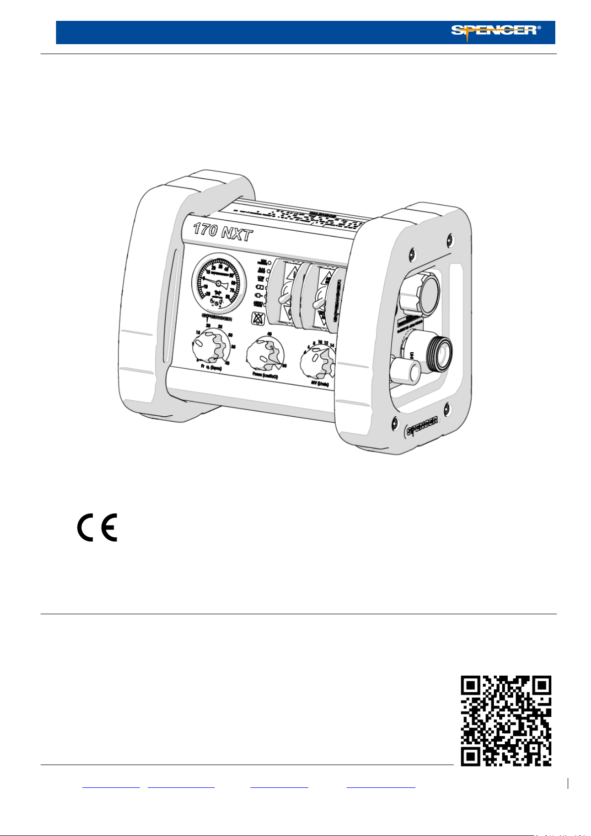
User manual
Spencer 170 NXT
Electronic lung ventilator
0123 Class IIb Medical Device, compliant with the Medical device directive 93/42/CE
Warning
The information contained in this manual is subject to change without notice.
The Diagrams are inserted only for reference and may vary slightly from the actual device.
Spencer Italia S.r.l. assumes no responsibility for any errors contained herein or for damage, accidents or consequences connected with the supply,
performance or use of this manual
Prima emissione: 1998
Rev. 3: 21/05/2019
SPENCER ITALIA SRL– Via Provinciale n° 12 – 43038 Sala Baganza (PR) - Italy
www.spencer.it | support.spencer.it - e-mail: [email protected] | service: [email protected] |Ph./Tel. +39.0521.541111
Quality System EN ISO 9001 – EN ISO 13485
1
Page 2

INDICE
1. MODELS 3
2. INTENDED USE 3
3. REFERENCES STANDARD 3
4. INTRODUCTION 3
4.1 Use of the Manual 3
4.2 Labelling and tracking control of the device 3
4.3 SYMBOLS 4
4.4 Warranty and support 5
5. WARNINGS 5
6. SPECIFIC WARNINGS 7
6.1 Requirements of operators 8
7. RESIDUAL RISK 9
8. TECHNICAL DATA AND COMPONENTS 9
8.1 Technical data 9
8.2 Components 10
8.3 Pneumatic diagram 11
9. INSTALLATION AND START-UP 11
9.1 Installation 11
9.2 Start-Up 14
10. FUNCTIONAL CHARACTERISTICS 15
11. INSTRUCTION FOR USE 16
11.1 Connection to the pneumatic supply 16
11.2 Turn on the device 16
11.3 Setting breathing parameters 16
11.4 Ventilation modes 17
11.5 Usage 17
11.6 Alarms and information signals 17
12. CLEANING AND MAINTENANCE 19
12.1 Cleaning 19
12.2 ORDINARY maintenance 19
12.3 Periodic maintenance 22
12.4 EXTRAORDINARY maintenance 22
12.5 Life span 22
13. TROUBLESHOOTING 23
13.1 Modalità di rientro per riparazione 24
13.1 How to return for servicing 24
14. ACCESSORIES 24
15. SPARE PARTS 24
16. DEMOLITION 25
Le informazioni contenute in questo documento sono soggette a modifica senza preavviso e sono da intendersi come impegno da p arte della Spencer Italia S.r.l. con riserva di
modifiche. I prodotti Spencer vengono esportati in molti paesi nei quali non valgono sempre identiche regole. Per questa ragione possono esserci differenze fra quanto qui descritto
ed i prodotti consegnati. Spencer lavora costantemente al perfezionamento di tutti i tipi e modelli dei prodotti venduti. Contiamo perciò sulla Vostra comprensione se dovessimo
riservarci la facoltà di apportare in qualsiasi momento modifiche alla fornitura nella forma, equipaggiamento, allestimento e tecnica rispetto a quanto qui convenuto.
Tutti i diritti sono riservati. Nessuna parte del documento può essere fotocopiata, riprodotta o tradotta in un’altra lingua senza previo consenso scritto della Spencer Italia S.r.l.
Avvertenza
© Copyright Spencer Italia S.r.l.
2
Page 3
1. MODELS
REFERENCE
DOCUMENT’S TITLE
EN 794-3
Lung ventilators - Part 3: Specific requirements of the ventilators operated by a source of energy
for emergency and transport.
CEI EN 60601-1
Medical electrical equipment Part 1: General requirements for safety
EN 60601-1-2
Medical electrical equipment Part 1: General requirements for basic safety and essential
performance - Collateral standard: Electromagnetic compatibility - Requirements and tests
Regulation 10
Uniform provisions concerning the approval of vehicles with regard to electromagnetic
compatibility
The standard following models can undergo change, revision and implementation without any notice.
Spencer 170 Electronic lung ventilator
Please contact the manufacturer for more informations about Kompak and Portavent versions.
The connection standard of the device is the one determined by the customer on the order.
2. INTENDED USE
Spencer 170 is a breathing control/assistance volumetric device, with electronic control of the respiratory function, capable of delivering two
different concentrations of medical gas with a single gas supply, equipped with mechanical and electronic safety systems able to monitor
some of the main breathing parameters. The range of volumes, respiratoy frequencies and monitoring systems for the safety of the patient,
allow its use in both adults and children. Is not indicated for use with newborns. The device is designed to provide temporary non-invasive
ventilation support for patients having a minimal essential breathing capacity. The device is designed for permanent installation inside
ambulances. If the device needs to be transported, is necessary to use an adequate transport bag.
3. REFERENCES STANDARD
As Distributor or final User of the products manufactured and/or sold by Spencer Italia S.r.l., it’s strictly required to know the law
dispositions applied in the Country of destination of the goods, applicable to the supplied devices (including the regulations about
technical specifications and/or safety requirements.
4. INTRODUCTION
4.1 Use of the Manual
This manual is intended to provide to the health care operator all the necessary information for its safe and appropriate use as well as
adequate maintenance of the device.
Note: this Manual is an integral part of the device, therefore it must be kept for the duration of the device and it must accompa ny the
device in case of change of ownership or destination. If the operating instructions received relate to a different product, you must
immediately contact the manufacturer before use.
The Spencer products manuals can be downloaded from the website http://support.spencer.it or they can be requested by contacting the
manufacturer. Exceptions are those items whose essentiality for reasonable and predictable use is such as to make it unnecessary to
prepare instructions in addition to the following warnings and the directions on the label.
Regardless of the level of experience gained in the past with similar devices, it is recommended to read carefully this manual
before installation, use of the product or maintenance.
4.2 Labelling and tracking control of the device
Each device has got an identification label positioned on the device itself and/or on its box, which includes identification data of the
manufacturer, the product, the CE mark, the serial number (SN) or lot number (LOT). It must never be removed or covered.
In case of damage or loss, request a duplicate from the manufacturer. Failure to do so will interrupt the validity of the guarantee as the
device can no longer be traced.
The Directive 93/42/EEC requires manufacturers and distributors of medical devices to keep track of the device location. If the device is
in a different location to the address where it was sent or to where it had been sold, donated, lost, stolen, exported or destroyed,
permanently removed from use, or if the device had not been delivered directly from Spencer Italia S.r.l., register your device at
http://service.spencer.it or inform Customer Care (see § 4.4).
3
Page 4
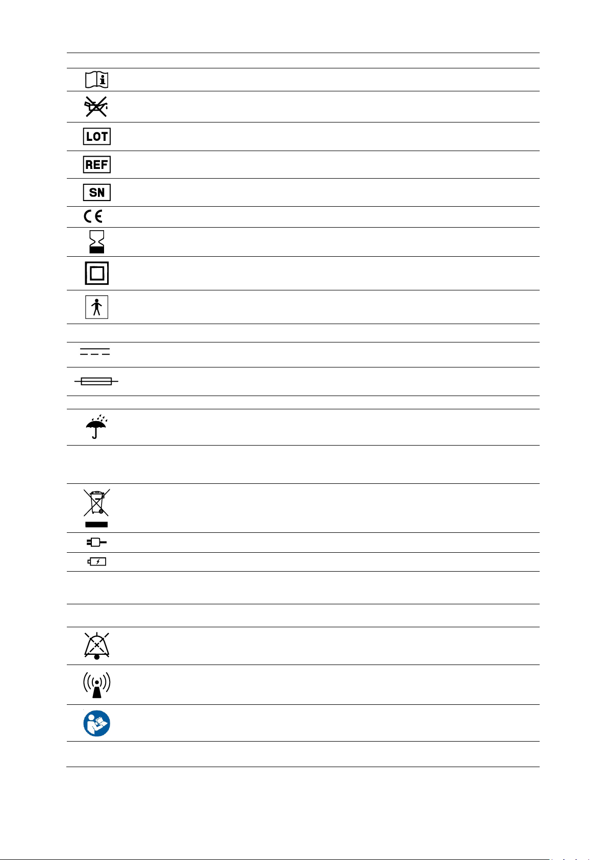
4.3 SYMBOLS
Symbol
Meaning
See instructions for use
Do not lubricate
Lot number
Product code
Serial number
0123
Product compliant with the Medical device directive 93/42/CE
The device must be used before the date indicated on the package (Accessories)
Protection against electric shock. Class II
Type BF applied part
~
Alternating current
Direct current
Fuse
Hz
Frequency (where applicable)
Keep in a cool and dry place
IP34
Protection of enclosures for electrical devices
First digit: protection against ingress of particulate greater than 2.5 mm diameter
Second digit: Protected against splashing water from all directions
Warning for the correct disposal of the product according to the European Directive 2012/19/UE
External power supply
Internal power supply
I
ON
O
OFF
AUDIO PAUSED
Non-ionising radiation
Obligation to read operating instructions
Caution: Federal Law restricts this device to sale by or on the order of a licensed practitioner
Restrictions for USA market
12 V DC
4
Page 5

4.4 Warranty and support
Spencer Italia S.r.l. guarantees that the products are without defects for a period of one year from the date of purchase.
For any informations regarding the correct interpretation of the instruction manual, the use, maintenance, installation or restore of the
product, contact Spencer Customer Care ph. +39 0521 541111, fax +39 0521 541222, e-mail [email protected]. In order to facilitate the
assistance service, please always indicate the lot number (LOT) or serial number (SN) shown on the label applied on the box or on the device.
Conditions for warranty and assistance can be viewed on http://support.spencer.it.
Note: Register and store with these instructions: lot (LOT) or serial number (SN) if any, date and place of purchase, date of first use, date of
servicing, name of the users and comments.
To guarantee the traceability of the products and to protect the procedures of maintenance and assistence of Yours devices,
Spencer has made available the ASSTEC portal http://service.spencer.it/asstec/login.aspx, which will allow you to view the data
of the products owned or on the market, to monitor and update the plans of periodic reviews, to view and manage
extraordinary maintenances.
5. WARNINGS
Warnings, notes and other important safety information are indicated in this section and clearly visible throughout the
entire manual.
User training
Note: despite all the effords, laboratory testing, post production tests and instruction manuals, the rules can’t always
reproduce the practical use, therefore the results obtained in the real conditions of use of the product could be notable
different.
The best instructions consist in the continuous practice under the supervision of trained and competent staff.
Regardless of the level of experience gained in the past with similar devices, it is recommended to read carefully this manual before
installation, use of the product or maintenance. If in doubt, contact Spencer Italia S.r.l. to obtain the necessary clarifications.
The device must be used only by a trained physician, having attended specific training for this device and not for similar products,
with appropriate clinical knowledge of artificial ventilation in order to correctly set the values available on the device according to
the patient’s clinical status.
The suitability of the user to use the product may be attested by the records of training, where the names of those trained, of the
trainers, dates and place are indicated. The register which certifies the eligibility of the operators to use the Spencer device must
be kept for a period of 10 years after the disposal of the device itself. This register will be made available to the competent
Authorities and/or manufacturer if requested. In the absence of such documentation, sanctions will be applied.
Do not allow any untrained person to help during the use of the product, because they could cause damage to themselves or to
others.
Note: Spencer Italia S.r.l. is always at your disposal to organise product training.
Installers training
The installer of the device must be able to ensure that all the equipments, systems, containers and connections are
compliant to the safety standards and regulations. This requires the knowledge of all the regulations and standards
applicable. In the particular case of connection to the main supply through a power adapter, this needs to be compliant with
IEC 60601-1, EN 60601-1-2 standards and periodic checks as prescribed by EN 62353 need to be established before the
installation of the device.
If these conditions are not met, the safety of the device and of the operators will be compromised.
Product functionality
The use of the product in any other way than the one described in the User Manual is forbidden.
Before each use of the device always check its integrity, as specified in the instruction manual. In case of damages/abnormalities that
could compromise its safety or functions, it is necessary to immediately remove the device from service and to contact the
manufacturer.
If any failure or malfunctioning of the device is detected, it must be immediately substituted with a similar item, so that the rescue
procedures are guaranteed without any interruption.
The product must not in any way be tampered with (modification, adjustment, addition, replacement). In such cases all responsibility
will be denied for any malfunctions or injuries caused by the product itself; moreover CE certification and product warranty will be
considered void.
Those who modified or have modified, prepare or have prepared the Spencer Italia S.r.l. medical appliances in such way that they no
longer serve the purpose for which they were intended, must satisfy the valid conditions for the first introduction into the market.
During the use of the devices you need to position and adjust them in such way that they won’t cause any obstructions to the
rescuers and/or any other rescue equipment.
Make sure that all the necessary precautions are taken in order to avoid the hazards that can arise from the contact with blood or
other body fluids, when applicable.
Ensure that the fixing system of the device is suitable to keep it fixed in the medical vehicle under all circumstances.
The warranty seaIs, if present on the product, must not be removed; in such case, the manufacturer will no longer recognize the
warranty of the product and will accept no responsibility in case of malfunctioning or damage caused by the product itself.
Avoid contact with sharp objects.
5
Page 6

Operating temperature: from -10°C to +40°C
Atmospheric pressure: from 70 to 110 kPa
Relative humidity: 15% - 95%
Storage
The device should not be exposed or be in contact with any source of combustion or inflammable agents. It must be stored in a dry
and cool place, repaired from sun and light.
Do not store the product underneath any object, heavy or not, which could cause structural damage.
Store and transport the device in its original packaging. Failure to do so makes the warranty void.
Before the storage of the device it’s necessary to recharge the batteries, remove and storage them in a separate room with a
temperature between -20°C and 35°C.
Storage temperature: from -30°C to +70°C.
Transient operating conditions are the same as operating conditions
Maintenance/Cleaning
Spencer Italia S.r.l. declines any liability for any damage, direct or indirect, which is a result of an improper use of the device and
its replacement parts and/or of any repairs made by someone other than the Manufacturer, which employs authorized internal
and external trained technicians; in this case the warranty is void.
During all the operations of checking, maintenance and cleaning procedures, the operators must always wear adequate protectio n
devices, such as gloves, glasses, etc.
If required from the Manufacturer in the User Manual, it must be established a plan of maintenance, periodic testing and extension
of the average lifetime, identifying an employee responsible for overseeing. He must ensure the basic requirements foreseen by the
Manufacturer in the User’s Manual.
The frequency of inspections is determined by factors such as legal requirements, type of use, frequency of use, environmental
conditions during use and storage.
Repairs must necessarily be carried out by an authorized Spencer Italia S.r.l. service centre, which in using original spare parts will
provide a quality repair service in strict accordance with the technical specifications given by the manufacturer. Spencer Italia S.r.l.
declines any liability for any damage, direct or indirect, which is a result of an improper use of the replacement parts of the device
and/or of any repairs made by unauthorized subjects.
Use only original components/spare parts and/or original accessories or approved by Spencer Italia S.r.l., in order to carry out any
operations without causing alterations or modifications to the device.
All the maintenance and revision activities must be recorded and documented with the corresponding report of technical assistance.
The documentation must be maintained for at least 10 years from the end of life of the product, and must be made available to the
competent authorities and/or the Manufacturer if requested.
The cleaning, scheduled for reusable products, must be performed in accordance to the directions provided by the Manufacturer in
the User Manual, in order to avoid the risk of cross-infections due to the presence of secretions and/or residuals.
The device and all of its components, if washed, should be allowed to dry completely before storing.
Regulatory requirements
As Distributor or final User or the products manufactured or sold by Spencer Italia S.r.l., it is strictly required to have a basic
knowledge of any legal requirements applied in the country of destination of the goods, applicable to the devices contained in the
supply (including laws regarding technical specifications and/or safety requirements). It is also required to have the necessary
knowledge to guarantee all aspects regarding the total conformity of the products to the regulations in the relevant territory.
Promptly notify Spencer Italia S.r.l. (already during the first product enquiry) when requesting details regarding any revisions to be
made by the Manufacturer in order to guarantee the conformity of the products to the territory’s legal specifications (including those
required by different regulations and/or regulatory provisions).
Act, with all due care and diligence, and contribute to ensure the conformity to the general safety requirements of all the devices
marketed in the territory, providing to the final users all the necessary informations to carry out periodical checks on the devices,
exactly as written in the User Manual.
Actively contribute during safety check of the product sold, by communicating any relevant information regarding the risks of the
product to the Manufacturer and to the competent authorities, so that necessary actions can be promptly taken.
The Distributor or final User is aware that in the event of any failure to conform to the above mentioned requirements will be
deemed fully responsible for any damage that might occur. Spencer Italia S.r.l. disclaims any responsibility and/or liability for your
non-compliance with the present regulatory provisions.
General warnings for medical devices
The user must read carefully not only the general warnings, but also those listed below.
It is not foreseen that the use of the device is prolonged beyond the time necessary for the first responders to complete their operations
and to complete the subsequent stages of transport to the nearest rescue point.
During the use of the device the assistance of qualified staff must be guaranteed, and at least one physician trained to the use of the
device must be present.
Follow the procedures and protocols approved by your internal organization.
6
Page 7

If disposable accessories are used, use only once and for only one patient. Do not wash or sterilize after use. Reuse may cause cross-
infection. Some symbols contained in this manual refers to the standard accessories included in the purchased device.
The activities of disinfection (and sterilization of the accessories if required) should be carried out in accordance with the parameters
given in the validated cycle, as specified in the technical standards. Sterilization could reduce the lifetime of the devices.
Do not use accessories after the expiration date indicated on the package, if present.
With reference to the D. Lgs. 24th February 1997, n. 46 emended by D. Lgs. 25/01/2010, n. 37 – Acknowledgement of Directive
93/42/CEE and 2007/47/CE concerning Medical Devices, we remind both public and private operators, that if in the exercise of their
activity they detect an accident involving a medical product, they are required to notify the Ministry of Health, under the terms and in
the manner established by the relative ministerial decrees and also to the manufacturer. Health care operators whether public or private
are required to communicate to the manufacturer any other inconvenience that may allow the adoption of measures that can ensure the
protection and health of patients and users.
6. SPECIFIC WARNINGS
The device is intended to be used on medical vehicles and not for home therapy.
The device must be used only in a professional healthcare environment, except for shielded room for magnetic resonance and near high
frequency surgical equipments. The installation should consider the parameters described in paragraph 9 according to electromagnetic
compatibility.
Portable and mobile RF equipments can affect the operation of the device.
The installation and placing of the device must consider what is described in tables of paragraph 9 in order to ensure that the device
maintain its essential performance and basic safety.
The use of cables or power supplies other than those approved by the manufacturer,can adversely affect the electromagnetic
performance of the device.
The use of RF equipments, including antennas, can adversely affect the lung ventilator. It is necessary to respect the distances from the
lung ventilator and its supply cables as listed in the paragraph 9.
The use of accessories other than the one aprroved by the manufacturer can cause increased electromagnetic emissions or a reduction of
the immunity level of the device.
The device should not be used adjacent to or stacked with other equipments. If adjacent or stacked use is necessary, the device should
be observed carefully to verify normal operation in the configuration in which it will be used.
Failure to follow warnings related to the electromagnetic compatibility can compromise the essential performance and the basic safety
of the device. It can affect the proper operations of components, the software, unexpected change or behavior in the ventilation mode,
false alarms, interruption of operations or wrong measurement of ventilation parameters.
Portable RF communications equipments should be used no closer than 30 cm from any part of the device, including cables. Otherwise,
the performance of the device could be compromised.
In order to maintain the essential performance and basic safety of the device, is essential to check before and after each use the integrity
of the electrical connections, and to verify that the environment in which the device is installed has not been changed by the installation
of additional devices.
Do not use the device with patients of age between 0 and 18 months, and with patients with not drained pneumothorax.
Do not use the device on patients with respiratory arrest or that don’t have minimal essential breathing capacity.
The device is intended for NIV. It is not suitable for procedures that requires intubation.
Do not use if the device presents any kind of damage or poor cleaning state.
The proper operation for the lung ventilator is closely linked to the suitability of the pneumatic power source. Is therefore essential to
check that the pneumatic supplies comply with the requirements described in this manual as well as to specific guidelines and standards
for such devices.
Ensure that the medical gas supply is free from condensation, residual materials and/or substances which may compromise the proper
operation of the device and the efficacy of the therapy or that could contaminate the patient.
The device must be protected from bumps, falls and spillage of liquids that could damage the device.
Remove the battery if the device is stored or when unused for a long time.
The device must be used by a physician trained in the use of this product.
The user must not have impairments that prevent proper reading and interpretation of informations displayed on the device and prevent
proper operation of controls.
Do not wash or clean the device with water jets or pressurized air.
Do not use drying machines.
Condensation, water, ice and dust accumulation can affect the correct functioning of the device, making it dangerous for the patient and
for the operators.
Before and after each use, check the status of the enclosures and of the fixing system of the device; if altered or yielding is noticed, is
necessary to restore its security status before using the device. Otherwise we assume no responsibility about proper functioning or any
damage caused by the device.
Regularly check the status of electrical and pneumatic connections.
Before turning on the device, charge the battery for at least 7 hours
The battery should never be completely discharged.
If any failure or incorrect functioning of the device is detected, the ventilation must be immediately restored with a similar device or a
manual one in order to ensure the life support functions without interruption.
Before each use of the device the perfect operating state of the device must be checked as specified in the User manual. If any damage
or abnormalities which could in any way influence the correct functioning and the safety of the device, of the patient and or of the user
are detected, the device must be immediately removed from service and the Manufacturer must be contacted.
7
Page 8

When the device is being used, the assistance of qualified staff must be ensured.
The device must always be accompanied by a replacement unit and/or by a manual ventilation system in order to ensure the possibility
to intervene on the patient in any case. The use of Spencer manual resuscitators is suggested.
If connected to the 220V main supply by an adapter, is necessary that its features are like the ones described in this manual, has passed
the test for electromagnetic compatibility according to EN 60601-1-2 and electrical safety according to IEC 60601-1 and IEC 62353
reporting the specific marking, and does not affect the electrical safety and electromagnetic parameters of the ventilator.
The batteries of the device must be replaced every year regardless of the number of recharge cycles.
Do not leave the patient without the assistance of at least one doctor or operator with clinical skills on artificial ventilation when the
device is used.
The device is equipped with warranty seals. If removed, the manufacturer will no longer recognize the product warranty and accepts no
responsibility for improper operation or damage caused by the device.
If the device comes with disposable accessories, these should be used of only one patient. Cannot be washed, sterilized or re-sterilized
after use.
If the device comes with accessories with limited lifespan, do not use them after the expiration date.
The device should not be exposed to or come into contact with any source of combustion or inflammable agents.
Store in a cool, dry, dark place and do not expose to direct sun.
Do not store the device underneath any heavy objects which could cause structural damage.
Store and transport the device in its original packaging.
Position and adjust the device taking care not to cause any obstruction to rescuers and or any other rescue equipment.
The device must be used in a ventilated environment.
The utilization of the ventilator with power sources and environmental conditions different from the indicated ones compromises the
safety of the operations and of the device itself.
Do not lubricate any part of the device. It’s not required by any kind of maintenance and could cause fire hazard.
The artificial ventilation can have side effects. In order to identify the hazards associated with the use of the device, related to the clinical
conditions of the patient, is essential the presence of an expert doctor who can evaluate the actual benefits provided by the artificial
ventilation and who is able to determine if the ventilator can be used. Side effects are only partially limited by the time of use of the
device, intended for emergency and not for prolonged therapy.
For the use of the ventilator, a specialized doctor must be present. The doctor will be able to determine if the technical specifications of
the device makes it suitable to be used on a specific patient and will be the sole responsible for the definition and setting of the
ventilation parameters.
Do not use the device in presence of inflammable substances and anesthetics.
The device is not intended for use in oxygen enriched environment.
Do not use the device if the condition of the paragraph 9 are not met.
Do not use the device if it has not been subjected to scheduled maintenance or maintenance required by a normal use.
Use only accessories approved by the manufacturer.
Do not connect the device to the patient through antistatic conductive tubes.
The installation must be performed ensuring appropriate distances between devices that could have each other electromagnetic
interference as specified in paragraph 9.
The device is intended for NIV and, as such, is generally not suitable in the following cases:
Respiratory arrest or severe cardiorespiratory impairment – Uncooperative patients (coma, shock, altered state of consciousness) –
Excessive secretions – copious bronchial secretions and/or need of frequent suction – Vomiting – Inability to protect upper airways –
Obstruction of upper airways – Cranio-facial trauma or burns – Recent facial, upper gastrointestinal tract or upper airways surgery –
anatomic lesions of the upper airways - Life-threatening hypoxemia – Hemodynamic instability – Sever comorbidities – Undrained PNX –
Sever obesity.
NIV may have complications related to the interface or administred gases, including: Discomfort, facial erythema, claustrophobia,
inhalation of gastric regurgitation, nasal congestion, dry mouth, eye irritation, barotrauma, intolerance and agitation, hypoxia due to
mask removal.
6.1 Requirements of operators
Spencer 170 is a device intended for professional use only. Each operator must be trained in their use and maintenance of
good operating conditions. Do not allow untrained people to assist in the use of the product, as this may cause injury to
themselves or others.
Installers and operators must know all the standards applicable to the devices, accessories and systems connected to the
pulmonary ventilator.
Operators must be able to assess the integrity of the connections. They must also be able to evaluate any anomalies of the
supply systems communicating the problem to the responsible figures, interrupting the use of the devices connected to it.
The abilities of all operators must be considered before determining their role in the employment of the device.
The device can be used only by specialized staff which will be able to determine if the technical specifications of the devic e
make it suitable to be used on a specific patient and will be the sole responsible for the definition and setting of the
ventilation parameters.
8
Page 9
7. RESIDUAL RISK
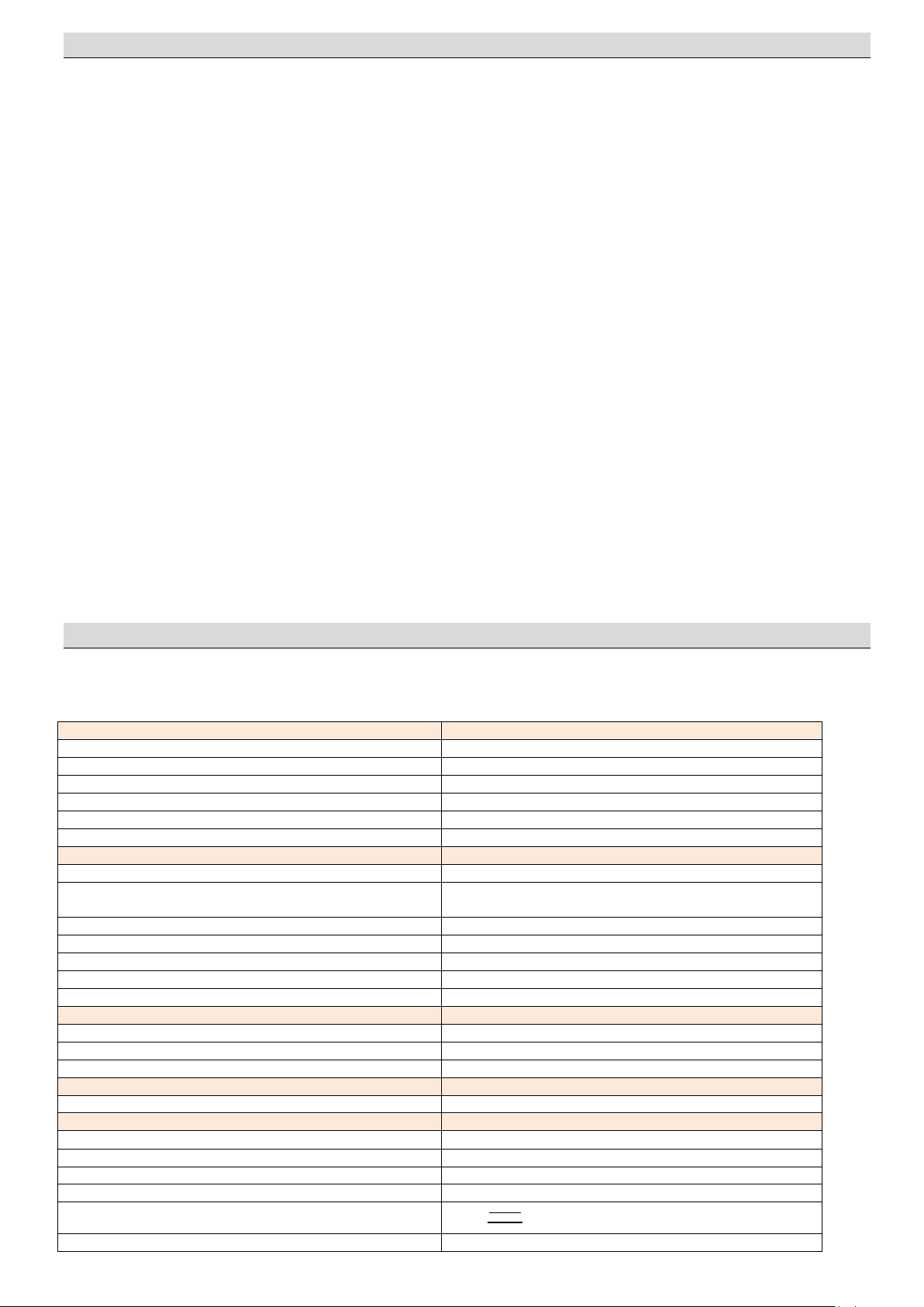
DIMENSIONALS
Width
269 mm
Height
210 mm
Depth
177 mm
Weight
3,32 ± 0,2 kg
Patient circuit weight
242 g
Patient circuit volume
400 ± 20ml
Power supply
Voltage
12 Vcc (-15% + 25%)
AC/DC Adapter
Input: 100-240VAC, 50/60Hz; 0,7-0,35A
Output: 12V DC
Power consumption max
700 mA
Main battery
12V NiMh 1,8Ah
Autonomy
About 3 hours
Charge time
About 10 hours
Secondary battery
9V 6LR61
Pneumatic supply
Intended gas
Medical oxygen
Input pressure
From 280 to 600 kPa
Maximum flow rate required
140 l/min
FUSE
F1L250V
Fast 5x20mm 1A
VENTILATION
Modality
CMV
Volume/minute
From 2 to 20 L/min
Frequency (F)
from 5 to 40 BpM
Pressure limit
from 20 to 60 cmH2O
Tidal Volume
FiO2
60% (AIR MIX) o 100% (NO AIR MIX)
The residual risks listed below have been identified exclusively in reference to the intended use of the device.
The installation and use without complying with the distances between electrical and electronic devices in reference to elect romagnetic
compatibility, could lead to malfunction of such devices.
Installation carried out by untrained personnel can lead to detachment of medical gas pressurized tubes, resulting in damage to people
or impossibility to carry out rescue operations.
Installation carried out by untrained personnel, could result in inadequate fastening of the device inside the ambulance, wit h consequent
risks related to its instability or mobility.
The connection to a gas supply having impurities or traces of condensate can compromise the good functioning of the device, altering its
functional characteristics and causing harm to patients.
The connection to a power source with higher voltage than described in this manual can make the device not usable.
The connection to a power source with lower voltage than described in this manual can result in a battery recharge failure an d in a
device block.
Failure to check the compliance of the pneumatic supply, may result in unattended therapy interruption.
The use in environmental conditions different from those specified in this manual, can damage the sealing elements resulting in leakage
of gas, deviations from the set flow values or condensation.
The use in presence of flammable and/or anesthetic gas may cause fire risks.
A prolonged use without adequate humidification downstream the device, can cause dryness of the patient airways.
The use of Air Mix mode in polluted atmosphere can result in serious damage to the patient.
The use of adult breathing circuits on pediatric patients may cause barotrauma.
Wrong choice of the mask size, can lead to oxygen leakage decreasing the effectiveness of the ventilation therapy or leading to improper
operation of alarms.
The artificial ventilation can have side effects. In order to identify the hazards associated with the use of the device related to the clinical
conditions of the patient, its essential the presence of an expert doctor who can evaluate the actual benefits provided by the artificial
ventilation and able to determine if the ventilator can be used. The doctor will be able to assess the type and cause of respiratory
insufficiency, ensuring adequate therapy evaluating the actual need and possibility to use the ventilator setting the proper values in
relation to the clinical condition of the patient. The absence of such figure can seriously compromise the patient safety because of
inadequate treatment, ineffective or due to an improper use of the device.
Side effects are only partially limited by the time of use of the device, which should never exceed the time for the transport of the patient
on the ambulance. Risks arising from prolonged use, are closely linked to the side effects of NIV.
The reuse of unsterilized patient circuits, involves risks of infection for patients and operators.
8. TECHNICAL DATA AND COMPONENTS
Note: Spencer Italia S.r.l. reserves the right to make changes to specifications without prior notice.
8.1 Technical data
9
Page 10
I/E Ratio
1:2
High pressure alarm with frequency <20 bpm
60 mbar ± 5%
High pressure alarm with frequency >20 bpm
25 mbar ± 5%
Respiratory resistance
Valve
Filter
Breathing tube
2,5 cmH2O espiraz.
1,73 cmH2O inspiraz.
a 50 l/min
2,5 cmH2O
a 60L/min
0,12 cmH2O a 30l/min
0,51 cmH2O a 60 l/min
Breathing tube compliance
Less than 2% of the volume
MANOVACUOMETER
Measuring range
from -20 to +80 mbar
Precision
1,6 (maximum error ± 1,3 mbar)
MAXIMUM DEVIATION FROM SETTINGS
Volume/minute
± 15%
Frequency
± 1 BpM
Pressure limit
± 5 mbar
Allarms
High priority
High pressure – Pnenumatic supply – Low battery
Medium priority
Batteria parzialmente scarica
Maximum audio paused time
100 s
Acoustic level
80 ± 10db
Classifications
Classification according to directive 93/42/CE
IIb
Classification according to IEC 60601-1
Classe II if externally powered
Internally powered if operating with internal battery
Classification applied part
(Breathing tube, filter, connector, valve, mask)
BF
Enclosure protection according to IEC 60529
IP44
Protected against ingress of particles with diameter greater
than 12mm. Protected against splashing water from all
directions
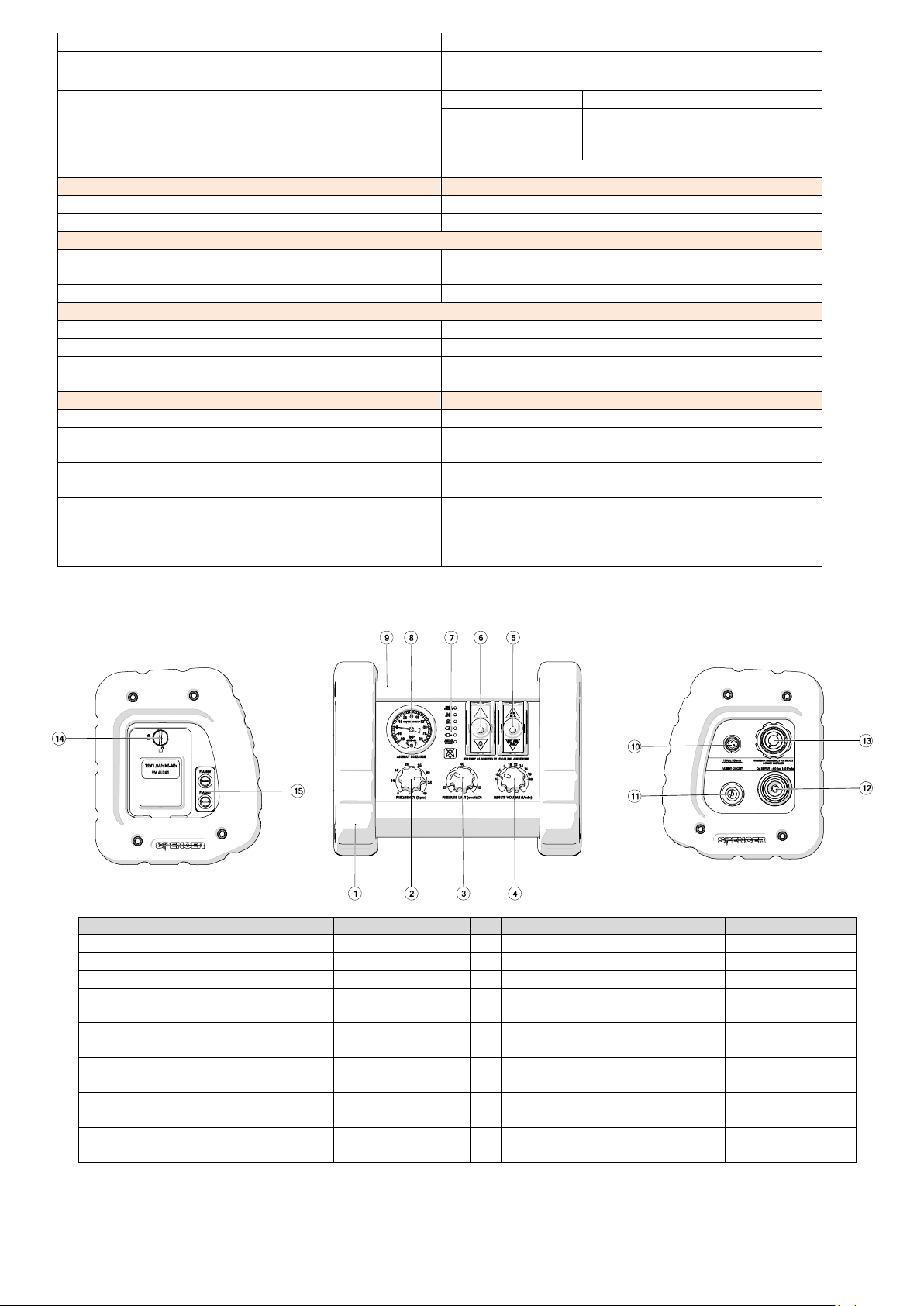
N°
Description
Material
N°
Description
Material 1 Lateral bodies
PE 9 Main body
Al
2
Frequency adjustment knob
Al
10
Power supply connector
Nylon 66/Brass
3
P
MAX
Adjustment knob
Al
11
Patient circuit connector
Al
4
Flow adjustment knob
Al
12
Pneumatic supply input
Brass, nickel plated
brass, ABS
5
AIR MIX/NO AIR MIX selection lever
Rubber covered
steel
13
Air input
Al 6 ON/OFF switch
Rubber covered
steel
14
Battery compartment panel
ABS
7
LED alarms section, segnalations
and audio paused time
Integrated in the PC
panel
15
Fuse holders
PE
8
Manovacuometer
Copper
alloy/Steel/Al
8.2 Components
10
Page 11
Guide and Manufacturer's Declaration
170 ventilator is intended for use in the electromagnetic environment specified below. The customer or the user of the ventilator 170 must ensure that it is
used in such an environment.
EMISSION TESTS
Conformity
Guide to the electromagnetic environment
Emissions in RF CISPR 11
Group 1
The 170 ventilator uses RF energy only for its
internal functions. Its RF emissions are therefore
very low and unlikely to cause any interference
with electronic equipment nearby.
Emissions in RF CISPR 11
Classe B
The 170 ventilator is suitable for use in all
environments including domestic as well as those
directly connected to a low-voltage public
network source supply of which supplies
buildings used for domestic purposes.
Harmonic emissions IEC 61000-3-2
Emissions as a result of voltage fluctuations /
flicker IEC 6100-3-3
Conform
The device comes with the following accessories not shown in this manual:
Patient circuit
It consists of a corrugated tube, face mask, non-rebreathing valve, straight fit and bacterial filter. Patient circuits or their components
approved to be used with the pulmonary ventilator are those listed in paragraph 15.
Oxygen connection tube
Allows the connection of the device to the oxygen supply.
Devices intended for transport are equipped with a suitable bag and include standard accessories stored in dedicated compartments
inside the systems.
Those accessories are:
- 2l Oxygen tank
- Pressure reducer with the connection standard specified in the order.
- Helicoidal mouth opener
- Tongue forceps
- Guedel cannulas
8.3 Pneumatic diagram
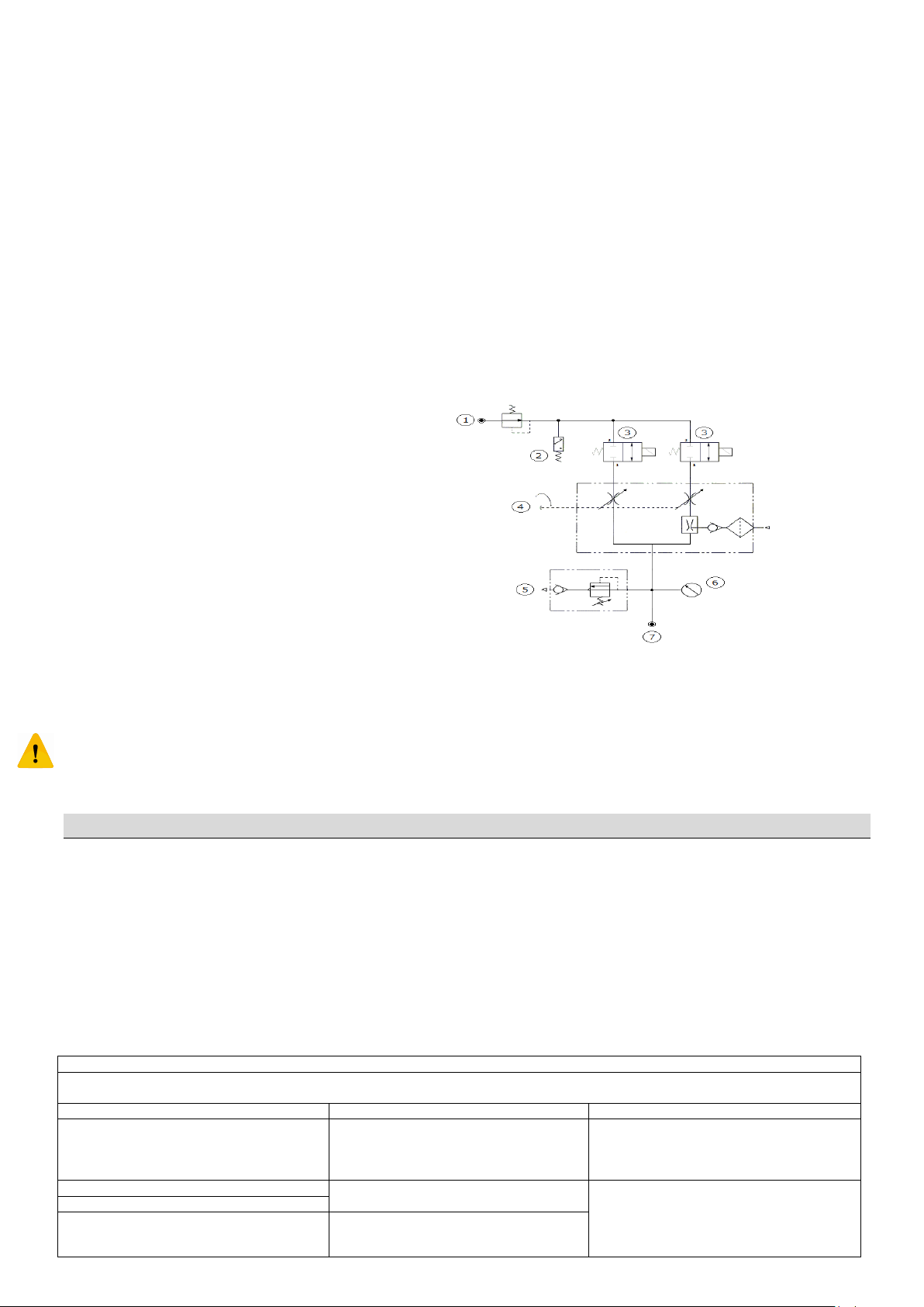
The lung ventilator 170, has an internal pneumatic circuit according to the following diagram:
1. High pressure source
2. Low pressure switch
3. Electrovalve
4. Minute/Volume mixer
5. Overpressure valve
6. Manovacuometer
7. Medical gas output – patient circuit
Inside the circuit, the incoming pressurized medical gas, is sent to the mixing block by means of a device operated by a valv e controlled by
the electronic circuit of the device. When the device is turned off the pressurized medical gas, even if introduced in the device, is not
delivered because intercepted by the electrovalve in closed position. Everything is controlled by the electronic circuit of t he device, which
also controls the main breathing parameters. This diagram is provided only to illustrate the operation of the device. It is not allowed to
intervene in any way on it as well as on the electronic circuit. If opening of the case of the device or any other type of un authorized
modification will be found, the warranty would be voided and Spencer Italia will not have any liability related to the functionality and use
of the product. The pneumatic circuit can be modified or implemented without prior notice.
9. INSTALLATION AND START-UP
9.1 Installation
Warning: The device is shipped with unplugged battery. Connect the buttery before the start-up.
The installation of the device is a critical step to ensure a proper operation. When the product is recieved, verify that:
The packaging is intact and has no signs of impacts, falls and isn’t wet.
All the items in the accompanying list are present
The device does not show any kind of damage
Ensure that the vehicle in which you want to install the device, is manufactured in compliance with EN 1789.
The device, tested in the laboratory of a notified body, has successfully passed all the electromagnetic test required by the harmonized
standards. It is designed to be used in the electromagnetic environment described below. The customer, installer and user must be able to
ensure that these conditions are always respected.
11
Page 12
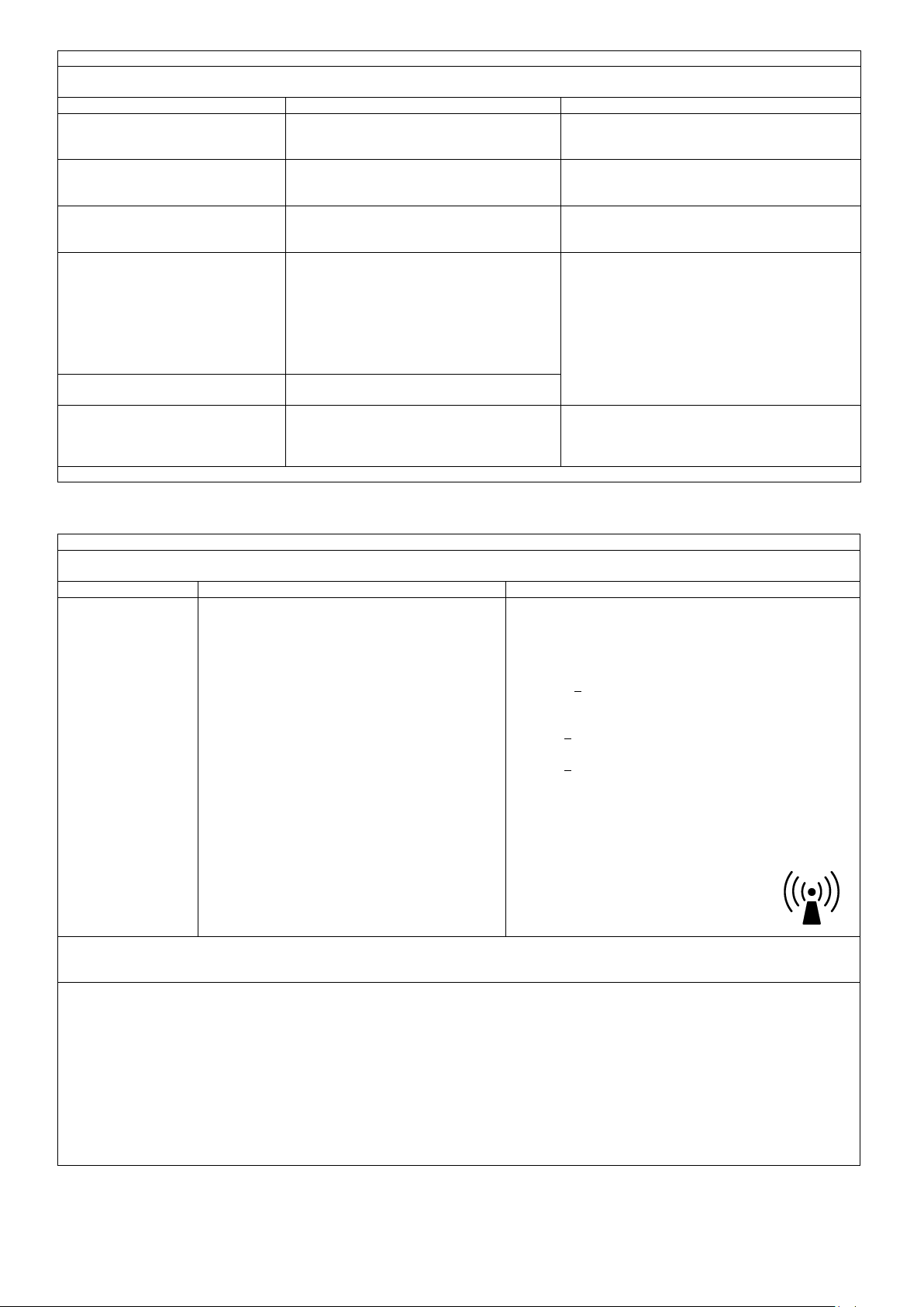
Guide and Manufacturer's Declaration
The 170 ventilator is intended for use in the electromagnetic environment specified below. The customer and / or user of the ventilator 170 must ensure
that the device is used in such environment.
IMMUNITY TEST
Conformity level
Guida all’ambiente elettromagnetico
Electrostatic discharge (ESD)
IEC 61000-4-2
± 8kV at contact
± 2 kV, ± 4 kV, ± 8 kV, ± 15 kV in aria
Floors should be wood, concrete or ceramic tile. If the
floors are covered with synthetic material, the relative
humidity should not exceed most 30%.
Electrical fast transient/burst
IEC 61000-4-4
± 2kV power supply
± 1kV or input/ouput lines
Mains power quality should be that of
a typical commercial or hospital
environment.
Over voltage
IEC 61000-4-5
± 0.5 , 1kV for line to line surge
0.5, 1, 2kV for line to ground surge
Mains power quality should be that of
a typical commercial or hospital
environment.
Voltage dips
IEC 61000-4-11
0 % UT; 0,5 cycles at 0°, 0°, 45°, 90°, 135°, 180°,
225°, 270° and 315°
0% UT 1 cycles and 70% UT 25/30 cycles (25 at
50Hz and 30 at 60Hz)
Single phase at 0°
Mains power quality should be that of
a typical commercial or hospital
environment. If the user of the
lung ventilator 170 requires
continued operation during power
mains interruptions, it is recommended
that the lung ventilator 170
be powered from an uninterruptible
power supply or a battery.
Voltage interruptions
IEC 61000-4-11
0% UT; 250/300 cycle
Power frequency (50-60 Hz) magnetic
field
IEC 61000-4-8
30 A/m
Power frequency magnetic fields
should be at levels characteristic of a
typical location in a typical commercial
or hospital environment
Note UT is the value of the tension of power source
Guide and Manufacturer's Declaration
The 170 ventilator is intended for use in the electromagnetic environment specified below. The customer and / or end user of the 170 ventilator must
ensure that the equipment is used in such environment.
IMMUNITY TEST
Level of conformity
Guide to the electromagnetic environment
Conducted RF
IEC 61000-4-6
Radiated immunity CEI
EN 61000-4-3
6 V
150kHz to 80MHz in ISM bands and amateur radio bands
80% AM a 1khz
10 V/m
80MHz to 2.7 Ghz
The equipment for communication in portable and mobile radiofrequency (RF) should not be placed near any part of the
appliance, including cables etc. and should be kept at a distance
never less than the recommended and calculated from the
equation applicable to the frequency of the transmitter.
Recommended separation distance
d = 0,583x
d = 1,2 x da 80Mhz a 800MHz
d = 2,3 x da 800Mhz a 2,7 GHz
where P is the maximum rated power output of the transmitter in
watts (W) according to the transmitter manufacturer and d is the
recommended separation distance in meters (m).
Field strengths from fixed RF transmitters, as
determined by an electromagnetic site survey
should be at less than the compliance level in
each frequency range b. Interference may occur
in the vicinity of equipment marked with the
following symbol:
NOTE 1 At 80 MHz and 800 MHz the separation distance for the range of higher frequency is applied
NOTe 2 These guidelines may not apply in all situations. Electromagnetic propagation is affected by absorption and reflection from structures, objects and
people.
a
The ISM (industrial, scientific and medical) bands between 150 kHz and 80 MHz are 6,765 MHz to 6,795 MHz; 13,553 MHz to 13,567 MHz; 26,957 MHz to
27,283 MHz; and 40,66 MHz to 40,70 MHz.
b
The compliance levels in the ISM frequency bands between 150 kHz and 80 MHz and in the frequency range 80 MHz to 2,5 GHz are intended to decrease
the likelihood that mobile/portable communications equipment could cause interference if it is inadvertently brought into patient areas. For this reason, an
additional factor of 10/3 has been incorporated into the formulae used in calculating the recommended separation distance for transmitters in these
frequency ranges.
c
Field strengths from fixed transmitters, such as base stations for radio (cellular/cordless) telephones and land mobile radios, amateur radio, AM and FM
radio broadcast and TV broadcast cannot be predicted theoretically with accuracy. To assess the electromagnetic environment due to fixed RF transmitters,
an electromagnetic site survey should be considered. If the measured field strength in the location in which the lung ventilator 170 is used exceeds the
applicable RF compliance level above, the lung ventilator 170 should be observed to verify normal operation. If abnormal performance is observed,
additional measures may be necessary, such as re-orienting or relocating the lung ventilator 170.
d
Over the frequency range 150 kHz to 80 MHz, field strengths should be less than 6 V/m.
12
Page 13

Recommended separation distances between portable and mobile communications equipment and the ventilator 170.
The 170 ventilator is intended for use in an electromagnetic environment in which radiated RF disturbance is controlled. The customer or the user of the 170
ventilator may prevent electromagnetic interference by maintaining a minimum distance between the communications equipment radio frequency (RF)
Portable and mobile equipment (transmitters) and the 170 ventilator, as described below and in accordance with the maximum output power of the
communication device
Maximum output power rating
of the transmitter
Separation distances according to frequency of transmitter (m)
(W)
From 150 kHz to 80 Mhz
Inside and outside ISM bands
d = 0,583x
From 80 Mhz to 800 Mhz
d = 1,2x
From 800 Mhz to 2,7 Ghz
d = 2,3x
0,01
0.058
0,12
0.23
0,1
0.184
0,38
0.73
1
0.583
1,2
2.3
10
1.844
3,8
7,3
100
5.83
12
23
For transmitters rated at a maximum output power not listed above, the recommended separation distance d in metres (m) can be determined using the
equation applicable to the frequency of the transmitter, where P is the maximum output power rating of the transmitter in watts (W) according to the
transmitter manufacturer.
NOTE 1 At 80 MHz and 800 MHz, the separation distance for the higher frequency range applies.
NOTE 2 The ISM (industrial, scientific and medical) bands between 150 kHz and 80 MHz are 6,765 MHz to 6,795 MHz; 13,553 MHz to 13,567 MHz; 26,957 MHz
to 27,283 MHz; and 40,66 MHz to 40,70 MHz.
NOTE 3 An additional factor of 10/3 has been incorporated into the formulae used in calculating the recommended separation distance for transmitters in the
ISM frequency bands between 150 kHz and 80 MHz and in the frequency range 80 MHz to 2,5 GHz to decrease the likelihood that mobile/portable
communications equipment could cause interference if it is inadvertently brought into patient areas.
NOTE 4 These guidelines may not apply in all situations. Electromagnetic propagation is affected by absorption and reflection from structures, objects and
people.
Guide and Manufacturer's Declaration
Immunity to proximity fields from RF wireless communications equipment
Test frequency (MHz)
Modulation
Immunity level (V/m)
385
Pulse modulation
(1)
at 18Hz
27
450
FM
(2)
±5Hz deviation 1kHz sine
28
710
Pulse modulation
(1)
at 217Hz
9
745
Pulse modulation
(1)
at 217Hz
9
780
Pulse modulation
(1)
at 217Hz
9
810
Pulse modulation
(1)
at 18Hz
28
870
Pulse modulation
(1)
at 18Hz
28
930
Pulse modulation
(1)
at 18Hz
28
1720
Pulse modulation
(1)
at 217Hz
28
1845
Pulse modulation
(1)
at 217Hz
28
1970
Pulse modulation
(1)
at 217Hz
28
2450
Pulse modulation
(1)
at 217Hz
28
5240
Pulse modulation
(1)
at 217Hz
9
5500
Pulse modulation
(1)
at 217Hz
9
5785
Pulse modulation
(1)
at 217Hz
9
The carrier shall be modulated using a 50 % duty cycle square wave signal.
As an alternative to FM modulation, 50 % pulse modulation at 18 Hz may be used because while it does not
represent actual modulation, it would be worst case.
If the environmental conditions are appropriate, is possible to install the device verifying that:
The installation floor is leveled and strong enough to withstand accelerations and vibrations to which the device could be subjected
during use on the medical vehicle. It’s suggested the use of a backplate.
The medical gas supply system has been regularly serviced or, in case of initial startup, the periodic maintenance has been programmed.
Fittings, pipes and all means of connection used in the system, are built according to the specific applicable standards.
Verify that purchased tubes and fittings respect the same standard requested for the device.
Distances between other electrical and electronic devices are like described in this manual.
The positioning of the device does not cause any type of obstruction inside the medical vehicle.
The power supply has the characteristics described in this manual. The pressure and flow delivered from the medical gas supply system,
have the characteristics specified in this manual.
The device must be installed using the dedicated surfaces on the lower side of the main body. Other fixation devices are available upon
request. Any other type of installation, precludes the safety and functionality of the device.
13
Page 14
Power supply
Medical gas supply
Voltage
12 V/DC
(-15% + 25%)
Pressure
From 280 to 600 kPa
Needed Current
> 1A
Flow
> 140 l/min
Internally powered OR Externally powered from
ambulance battery by dedicated 12V cigarette lighter
adaptor
Connection standard (If not
otherwise specified on
accompanying documents)
UNI
(Standard available BS, DIN,
AFNOR)
AC/DC adapter:
Manufacturer: Mean Well
Model: GSM25B12
Input: 100-240VAC, 50/60Hz, 0,7-0.35A
Output: 12Vcc 2,08A, 25W Max.
Connection specifics
Brown wire
Positive pole
Blue wire and schielding
Negative pole
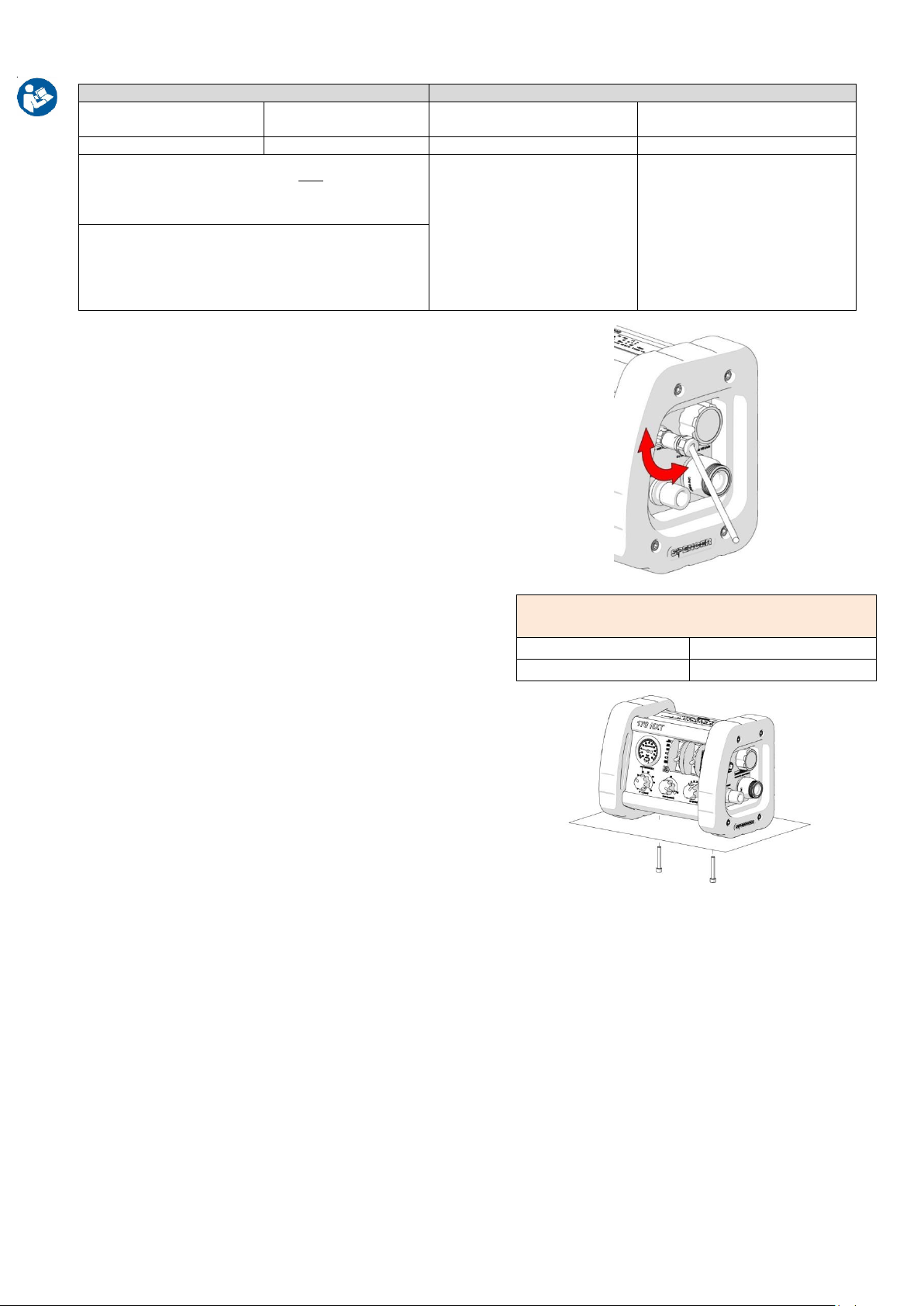
The device must be connected to electrical power supply and to a source of medical gas having the following characteristics:
The power cable supplied with the device, must be connected to the device
and at the other side must be connected to a cigarette lighter socket
installed inside the ambulance.
Screw the connector ring manually as much as possible.
Then tighten with a torque of about 2Nm. If the device has to be serviced,
you must disconnect it from the power supply.
If you wish to wire the cable to the mains power of the ambulance, remove
the plug, splice and connect according to the specifications in the table.
After installation and electrical and pneumatic connections, is necessary to
check the proper functioning of the device.
If the device is powered through a power adaptor connected to the mains
power, is necessary to verify that the mains comply with the specification of
the power adaptor.
If the device is connected to the mains through a power supply compliant
with EN 60601-1, the assembly should be considered an EM SYSTEM.
Typically, the power adaptor can be connected to a socket installed inside an
ambulance manufactured according to EN 1789.
The installation of the device must always allow the optimal view of the
control panel and must ensure easy access to the connections.
On the bottom of the device, there are two threaded pads for installation on
a flat floor.
- Drill two holes on the surface for the screws.
- Choose screws of appropriate length according to the installation surface.
- Tighten the screws until a safe fix is reached.
- Make sure the screws are fully seated. If they are not perfectly coupled with
the surfaces, is necessary to choose shorter ones or, if the distance between
the screw and the surface is reduced, apply washers.
9.2 Start-Up
For a proper and safe use of the product, proceed as follows:
For the first use, connect the battery because a new ventilator has the battery not connected
Ensure that power and gas supplies comply with the specifications in this manual. Is necessary to ensure that oxygen tanks and pressure
regulators comply with appropriate regulations and directives that can be applied to those devices. Their proper operation should always
be checked before each use..
Always check the residual content of the oxygen bottles.
Connect the patient circuit and all its components to the unit
Check that the pressure gauge is on “zero” position.
Turn on the device by pressing the ON/OFF button.
The device performs an autodiagnostic test by turning all leds on for about one second accompanied by 3 short sounds..
After this test, the device automatically starts the ventilation in controlled mode, in accordance with the previously set parameters. If this
does not happen, refer to the table “TROUBLESHOOTING”.
Adjust the breathing frequency.
Adjust the minute volume.
Carry out functional test of the overpressure valve in this way:
Close with the palm of one hand the patient outlet and turn the pressure limiting knob. Verify that the value indicated on the gauge is the
same set with the knob. The checks must be done on all the adjustment scale.
If the values are not the same or outside the tolerances, put the device out of service and contact the manufacturer or service center.
Carry out functional test of the alarm systems as described in paragraph 12.2.6
14
Page 15
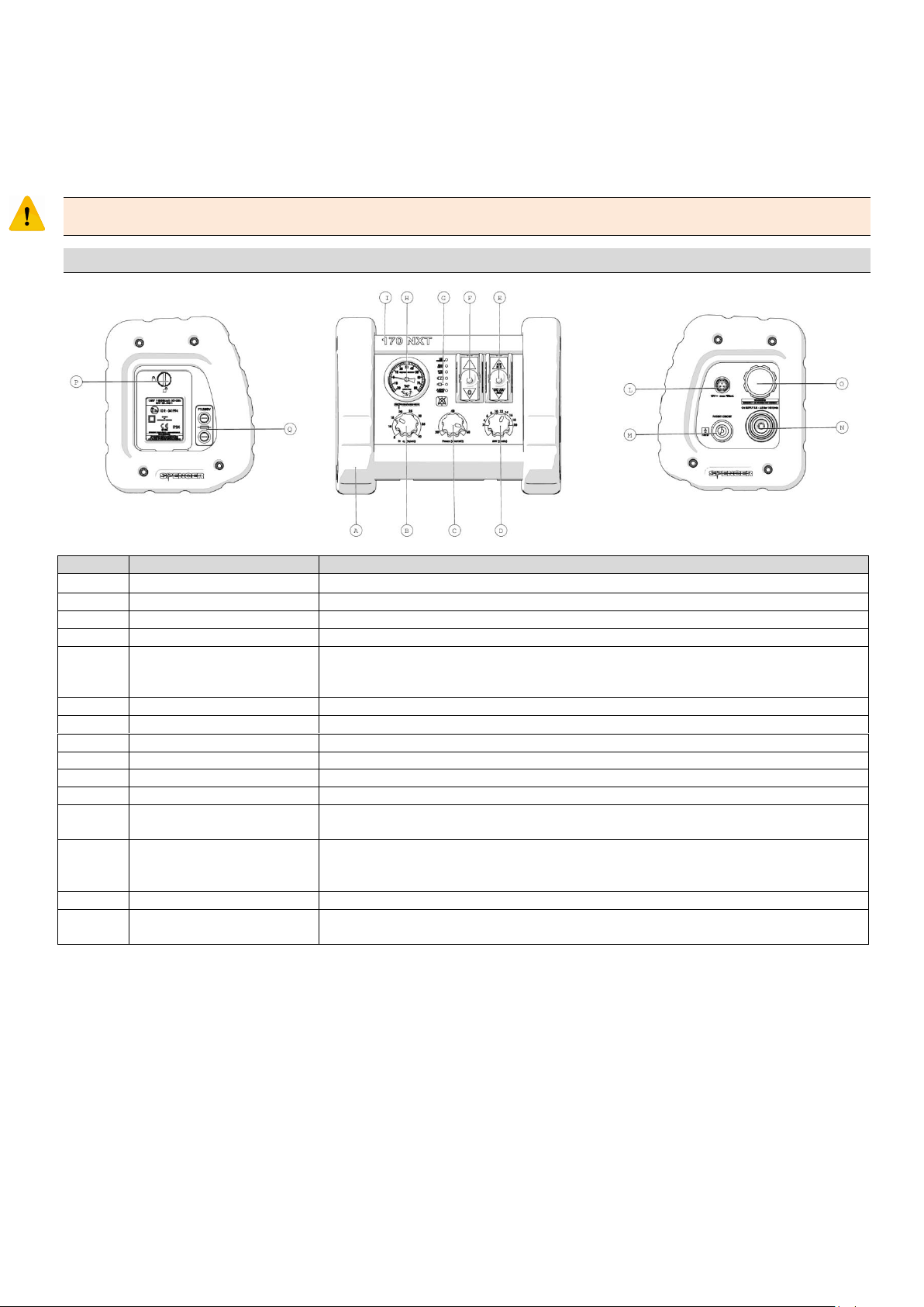
Once the tests are carried out, is necessary to:
Element
Description
Function
A
Side protections
Provide additional protection to the primary enclosure increasing the stability of the device.
B
Frequency adjustment knob
Allows to set the breathing acts per minute
C
P
MAX
Adjustment knob
Allows to set the maximum pressure limit that can be reached during ventilation
D
Flow adjustment knob
Allows to set the delivered volume minute
E
AIR MIX/NO AIR MIX selector
Allows to choose whether to use the medical gas delivered by the medical gas supply system
at 100% (NO AIR MIX) or at 60% (AIR MIX), mixing it with air taken from the environment in
which is placed the device.
F
ON/OFF switch
Turn on the device by pressing the “I” button, turn it off by pressing the “O” button
G
Alarm LED section
Provide visual feedback regarding the activated alarms or their audio paused status
H
Manovacuometer
Primary enclosure of the device
I
Main enclosure
Primary enclosure of the device
L
Power connector
Required to connect the power source
M
Patient circuit connector
Output at which the patient circuit must be connected.
N
Medical gas input
Input at which must be applied the tube connected to the medical gas supply system. The
standard used is UNI. This connection is marked O2 SUPPLY
O
Air input
Group for air intake. This component is identified by the words EMERGENCY AIR INTAKE, and
allows spontaneous breathing of the patient in the event of device failure, by drawing air
from the environment
P
Battery compartment panel
It is the access cover for the battery compartment. It can be removed using a coin.
Q
Fuse holders
They contain the fuses for internal battery and external power supply. The upper one is for
primary battery, the lower one is for external power supply.
Turn off the Spencer 170 by pressing the button “O” for about 2 seconds
Break off the medical gas supply
If the device is working properly and the conditions above are met, it can be considered ready for use; otherwise put the device out of
service and contact the manufacturer.
The patient circuits to be used in place of the one provided, are to be chosen from those approved by the manufacturer and listed in
paragraph 14.
Do not alter or modify the device arbitrarily; modifications may cause unpredictable operation and damage to the patient or rescuers and
will also void the warranty, relieving the manufacturer from any liability.
10. FUNCTIONAL CHARACTERISTICS
15
Page 16
For their use, the pulmonary ventilators require fundamental accessories that make up the patient circuit, which includes in the assembly
Component
Description
Straight fit 22/15
Allows the connection between the filter and the patient valve
Corrugated tube
Canalizes the medical gas flow and connects the devices of the patient circuit. It is directly
connected to the medical gas output placed on the ventilator
Patient valve
Equipped with overpressure and non-rebreathing valves, allows the connection between the mask
and the straight fit. It must be chosen according to the patient to be treated (Adult or Pediatric)
Filter
Antibacterial filter placed between the straight fit and the corrugated tube
Face mask
Is the main interface between the device and the patient
order the Mask, Patient valve, straight fit, antibacterial filter, corrugated tube.
Spencer 170 includes:
11. INSTRUCTION FOR USE
11.1 Connection to the pneumatic supply
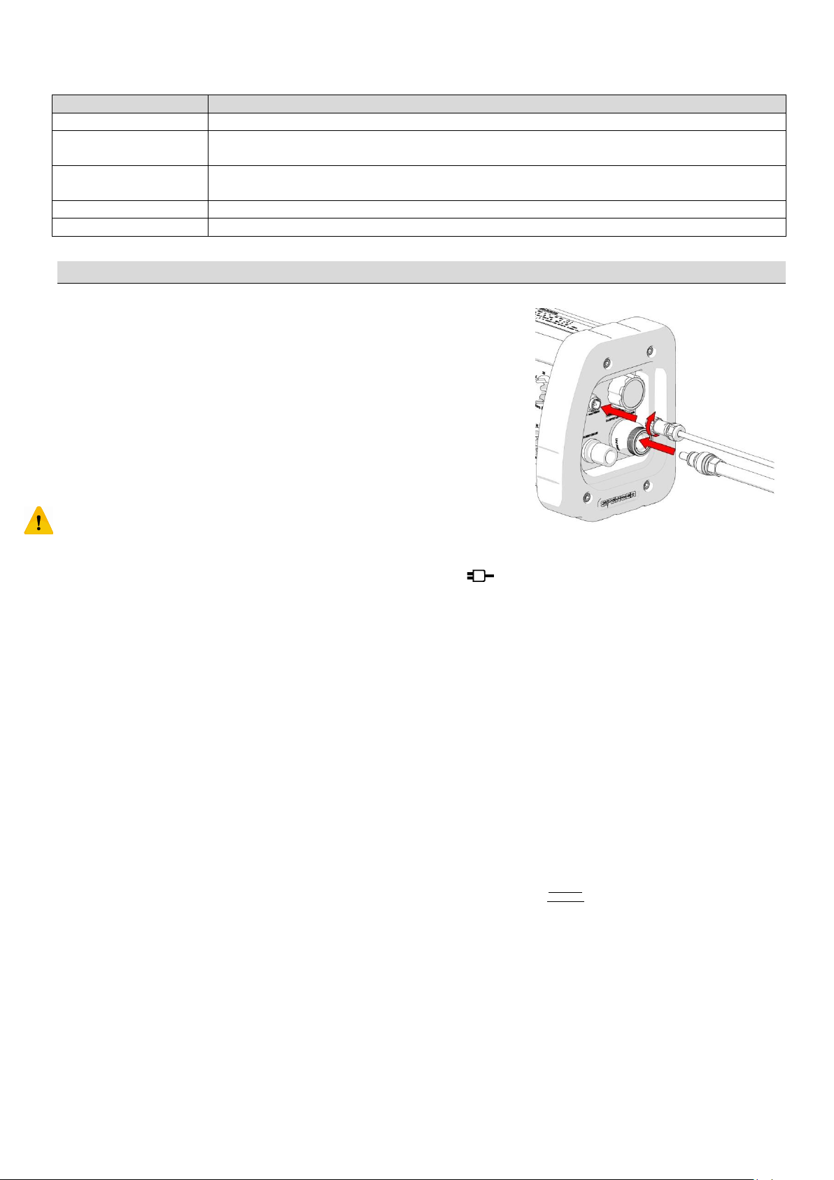
After the device has been connected to the power supply according to the
provided specifications, connect the pneumatic supply hose to the socket
placed on the pressure reducer installed on the oxygen tank. Insert then the
probe inside the socket on the connections side of the lung ventilator
pressing until it clicks confirming the proper connection.
To verify the integrity of the electrical connection, slightly pull the connector
verifying that no disconnection happens.
For the pneumatic supply, slightly pull the probe doing a little rotation at the
same time.
Connect the breathing tube to the output marked with “PATIENT CIRUIT” on the
connections side of the lung ventilator. The tube must be inserted for about 2,5 cm. If the
insertion is difficult, the tube can be slightly rotated during insertion making the operation
easier.
The breathing tube must not rotate easily and freely. If this happens, it is an obvious sign of damage to the hose or of its incompatibility with
the device.
In these conditions the device is ready for use, and this is identified by this LED .
To disconnect the device from the pneumatic supply, push the outer plastic part of the socket in axial direction while pulling out the probe.
11.2 Turn on the device
Turn on the device by pressing on the button identified with the symbol “I”.
The device will perform an autodiagnostic test by turning on all LEDs for about 1 second and emitting 3 short sounds.
When this test is concluded, the device automatically start the ventilation in “Controlled mode” according to the set parameters.
If the device is not working or there are different visual or acoustic signals, refer to the paragraph explaining the warning signs or the section
TROUBLESHOOTING.
On the frontal panel will be displayed the ventilation mode, the breathing phases and any alarms or informations related to the power or
pneumatic supplies.
11.3 Setting breathing parameters
On the frontal panel there are 3 adjustment knobs. Breathing parameters must be adjusted before applying the mask to the patient. During
these adjustments, the physician using the device must consider the patient’s weight, the Tidal Volume required by the patient and its
clinical conditions.
Volume minute adjustment
The Volume minute is the volume of gas delivered to the patient in a minute. It differs from the delivered volume for each breath (or Tidal
Volume) as this is closely related to the breathing frequency according to the relation
The device allows setting between 2 and 20 L/min
Breathing frequency adjustment
Rotating the frequency adjustment knob, is possible to set the number of breaths per minute.
The frequency has consequences both on the tidal volume according to the mentioned relation and on the activation level of the high
pressure alarm. The high pressure alarm is activated at 25mbar if the frequency is set higher than 20 breaths/min and at 60mb ar if the
frequency is less than 20 breaths/min.
The device allows settings between 5 and 40 breaths/min (bpm).
Pressure limit adjustment
Through this setting, is possible to limit the maximum pressure in the breathing circuit to the desired value. If the pressure limit is
exceeded, the volume minute is no longer guaranteed.
The device allow settings between 20 and 60mbar.
.
16
Page 17

11.4 Ventilation modes
Physiological high priority alarms
HIGH PRESSURE
Alarm specification
10 sequences of sound pulses spaced 2,5 seconds and dedicated led flashing two times per second
Reason of activation
The maximum pressure in the patient circuit has been exceeded.
This limit is activated at 60mbar if the frequency is set less than 20bpm and at 25 mbar if the
frequency is set higher than 20bpm
Possible causes of activation
1 – volume/minute set is to high
2 – the connection tube with the patient is crushed or obstructed
3 – Patient’s breathing resistances cause the activation of the alarm
Action to take
1 – decrease the volume/minute value
2 – free the tube and restore a safe condition
3 – Check that the ventilation parameters are adequate for the patient’s clinical conditions. Is
necessary to do more evaluation to ensure if intubation is needed. This means that the ventilation
must be carried out with other devices
CMV ventilation mode
This mode is the only one available on 170 and is selected by default when the unit is turned on. It consist in the erogation of the medical
gas to the patient according to the parameters set with the adjustment knobs.
With this mode, the inspiratory and expiratory time ratio is constantly 1:2.
Air Mix/No Air Mix Selection
The lever placed on the front panel, allow to choose between two available FiO
If in NO AIR MIX mode, the ventilator delivers only the medical gas coming from the main medical gas supply to which the device is
connected. If the supply system delivers oxygen, the ventilator will deliver to the patient an oxygen concentration of 100%. Selecting the
AIR MIX mode, the ventilator draws 60% of gas from the medical gas supply and the remaining 40% from the environment where th e
device used. In this case, if the main gas supply deliver oxygen, the concentration of this gas administered to the patient will be of 60%.
It is inappropriate to use the Air Mix mode in case of polluted environment. The device has a filter for incoming air subjected to periodic
replacement as specified in paragraph 12
levels.
2
11.5 Usage
The physician who directs rescue operation is responsible for the choice of the device to be used and for the clinical assessment s needed
for the proper use of this device and for the choice of the proper ventilation parameters.
Patient circuits used for the ventilation must be chosen among those approved by the manufacturer. For ventilation of pediatric patients, a
pediatric patient valve must be used.
The residual pressure of the medical gas supply must be regularly checked to ensure enough autonomy. The achievement of the pressure
of the residual valve of the oxygen bottle, would result in the shutdown of the device and in the activation of an alarm signal.
The device provides alarms intended to limit risks of wrong adjustments or needed for a safe use of the product.
Alarms can be silenced by pressing the button identified by the symbol placed on the frontal panel. The audio paused condition can be
identified by the illumination of the orange LEDs of the write “AUDIO PAUSED”. The audio pause function has no effect on lights and
alarms that are not active when the mute button is pressed.
For safety reasons, the alarms are not automatically disabled when the alarm condition no longer exist. To disable the audio paused
function and to terminate all active alarms, press the audio paused button for about 2 seconds.
The device has an internal 12V battery which provides an autonomy of about two hours when disconnected from the main power supply.
It’s also present a 9V backup battery needed for the operation of the alarms of the main battery charge status.
When the external power supply is active, the green led next to this symbol: will light continuously. If connected to the external
power supply and the battery is not fully charged, the charging will automatically start and the white led next to the symbol: will
light. Flashing of the white led next to the symbol: identifies a particular condition that do not allow to charge the battery. (See par.
11.6).
The real pressure in the patient circuit is always shown on the manovacuometer placed on the front panel.
In standard conditions it is suggested to remove any implants, evaluate the need of bronchoaspiration, hyperextend the patient’s head
and, to ensure that the airways are clear, position the face mask over the mouth and nose checking the adherence of the soft part of the
mask on the patient’s face, in order to obtain a sealed system. It is important to verify that the mask is suitable for the patient; in the early
stages of the ventilation it is suggested to force the adhesion of the mask to the patient’s face.
The adjustment method of the volume minute knob (by steps), prevents changes in the set parameters due to accidental contacts.
Resistance of the airways due to obstructions or external cardiac massage does not cause a variation of the respiratory volume and
frequency. In case of reduction of the compliance, the ventilator will react with a rise of respiratory pressure at a constant volume.
During ventilation, constantly monitor the patient’s physiological response in order to verify if the set parameters are correct or to ensure
absence of complications.
Note:
The medical gas flow is not influenced by pressure. The ventilator does not monitor the oxygen concentration (mechanical mixing). Unless
otherwise specified the parameters are expressed in ATPD (Ambient, Temperature and Pressure Dry).
At the end of service, turn off the device by putting the lever on the “O” position, shut down the pneumatic supply and proceed with the
necessary maintenance activities.
11.6 Alarms and information signals
Each visual, acoustic or visual/acoustic signal is generated by conditions requiring attention and intervention by the operator.
The device is equipped with high priority alarms and has informations signals as described below.
17
Page 18
Technical high priority alarms
GAS SUPPLY
Alarm specification
10 sequences of sound pulses spaced 2,5 seconds and dedicated led flashing two times per second
Reason of activation
The pressure of the pneumatic supply is low
Possible causes of activation
1 – The gas supply doesn’t have adequate performances for this device
2 – Oxygen tanks are empty
Action to take
1 – Put the device out of service and verify the performances of the gas supply.
2 – Verify the remaining pressure of the oxygen tanks considering the pressure of the residual valve.
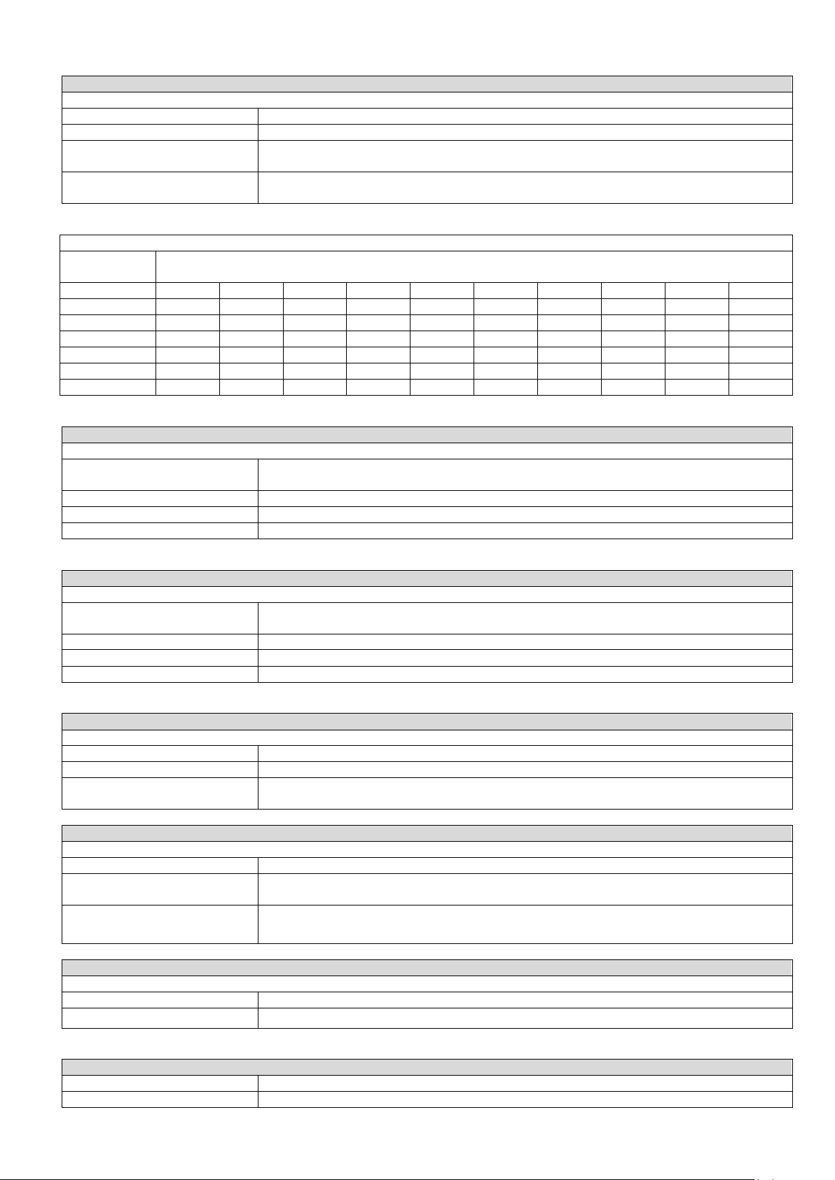
Autonomy expressed in minutes for a tank loaded at 200bar
Tank capacity
(liters)
Selected flow (l/min)
2 4 6 8
10
12
14
16
18
20
2
200
100
67
50
40
33
29
25
22
20 3 300
150
100
75
60
50
43
38
33
30
5
500
250
167
125
100
83
71
63
56
50
7
700
350
233
175
140
117
100
88
78
70
10
1000
500
333
250
200
167
143
125
111
100
14
1400
700
467
350
280
233
200
175
156
140
Technical high priority alarms
LOW BATT
Alarm specification
10 sequences of sound pulses spaced 2,5 seconds and dedicated red led flashing two times per
second
Reason of activation
The primary battery has reached a low charge level requiring intervention by the operator
Possible causes of activation
1 – The battery has a remaining autonomy of about 10 minutes
Action to take
1 – Connect the device to the external power source as soon as possible
Technical medium priority alarms
LOW BATT
Alarm specification
3 sequences of sound pulses spaced 2,5 seconds and dedicated yellow led flashing one time every
two seconds
Reason of activation
The primary battery has reached a charge level that requires attention by the operator
Possible causes of activation
1 – The battery has a remaining autonomy of about 30 minutes
Action to take
1 – Connect the device to the external power source as soon as possible
Other signals
Primary battery failure during charge
Signal specification
The write ON CHARGE is flashing
Possible causes of activation
The battery temperature is too high
Action to take
Wait for battery cooling
The device will start to charge the battery when the temperature reaches adequate levels
Other signals
Primary battery failure
Signal specification
LOW BATT flashes every 3 seconds emitting a short acoustic signal
Possible causes of activation
1 – The fuse is blown or the battery protection is interrupted
2 – battery not connected
Action to take
1 – Remove immediately the battery and use the external power source.
2 – Connect the battery
Other signals
AUDIO PAUSED
Signal specification
White led is on, next to the write AUDIO PAUSED
Meaning
Active alarms are silenced
Other signals
Signal specification
Other leds are on
Meaning
Failure of an internal component
Here is shown a table for general guidelines about autonomy of bottles of various capacities.
18
Page 19
12. CLEANING AND MAINTENANCE
USABLE PRODUCTS
NOT USABLE PRODUCTS
Disinfectants with aldehydes
Compounds that release halogens
Disinfectants with alcohol
Strong organic acids
Quaternary ammonic compounds
Compounds that release oxygen
Trichloroethylene
12.1 Cleaning
Failure to carry out the correct cleaning routine could increase the risk of cross infection, due to presence of body fluids and/or residuals.
The operator must always wear adequate personal protection such as gloves and mask, etc. during all checking and cleaning procedures.
The described operations must be performed after each use of Spencer 170.
Turn off the device
Isolate it from the power supply (if connected)
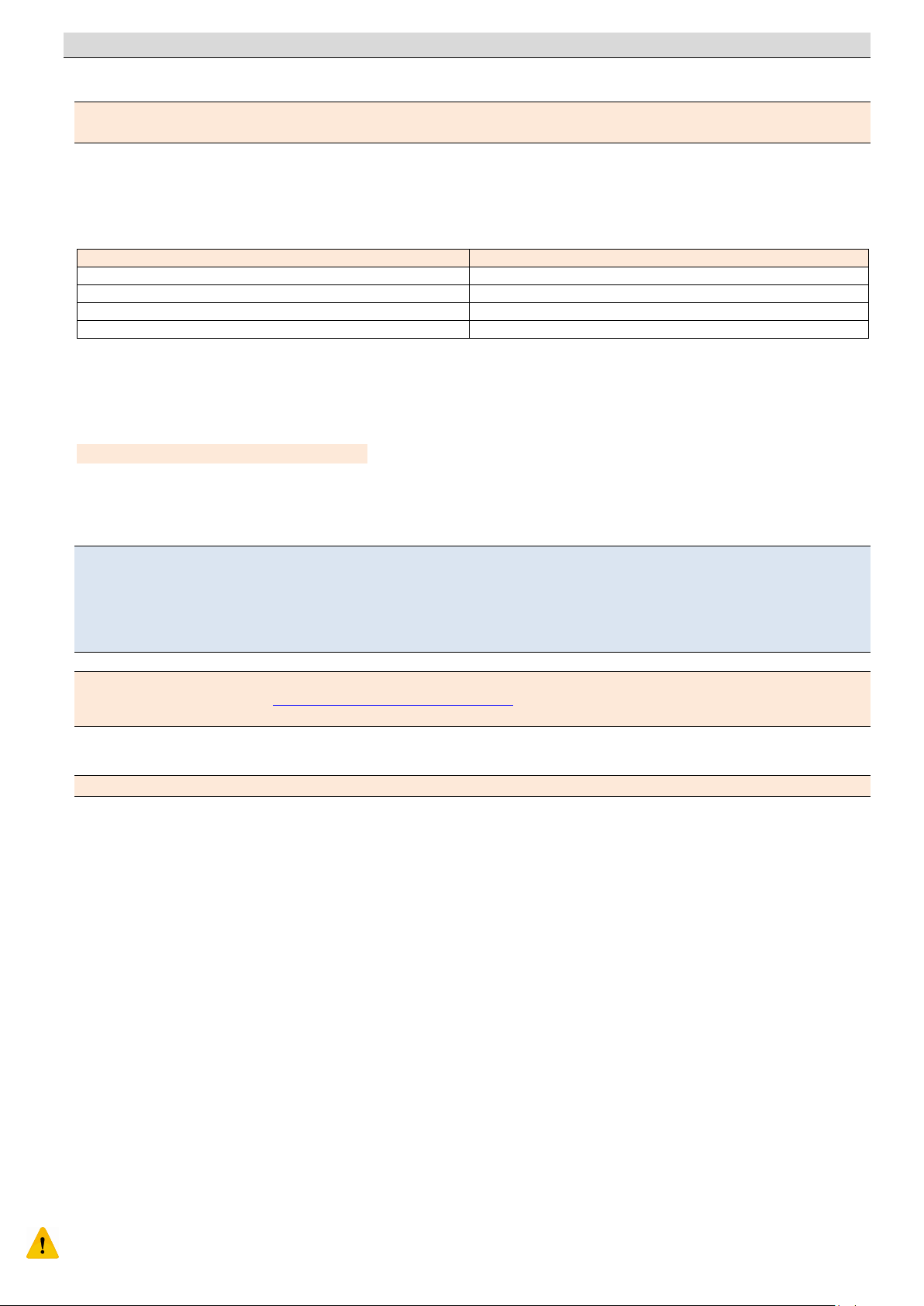
The cleaning of the external parts of the device can be carried out using suitable disinfectants for surfaces as described in this table:
Be careful to ensure that no kind of solution enters inside the oxygen socket..
If is used a disposable patient circuit, replace it.
If is used a reusable patient circuit, disassemble every part and sterilize according to a validated procedure.
Similarly, replace or sterilize the mask.
After confirming the ventilator and all accessories are completely dry, is possible to reconnect the device to the power supply.
The use of high pressure water is prohibited, because it should penetrate into the device causing risks of corrosion of components
and risks of electric leakage and short circuits. During every cleaning procedure, check that were not used any kind of lubricants.
12.2 ORDINARY maintenance
Establish a maintenance program and periodic testing routine, identifying an employee responsible for this. The person to whom the
ordinary maintenance of the device is entrusted must ensure the basic requirements foreseen by the manufacturer in following paragraphs
are inspected.
All maintenance and periodic servicing activities must be registered and kept together with the servicing reports. These documents have to
be kept for a period of 10 years after the disposal of the device itself. This register will be made available to the competent authorities
and/or manufacturer if requested.
To guarantee the traceability of the products and to protect the procedures of maintenance and assistence of Yours devices, S pencer has
made available the ASSTEC portal http://service.spencer.it/asstec/login.aspx, which will allow you to view the data of the products owned
or on the market, to monitor and update the plans of periodic reviews, to view and manage extraordinary maintenances.
Routine maintenance of the device must be carried out by operators in possession of specific qualifications, trained and experienced in the
use and maintenance of the device.
The operator must always wear adequate personal protection such as gloves and mask, etc. during all checking and cleaning procedures.
Checks to be carried out before and after each use and at deadline indicated above, are as follows:
General functionality of the device
Cleanliness of the device (remember that the failure of cleaning may cause the risk of cross infections)
Correct fixation of all nuts, bolts and screws
No structural part is deformed or compromised
Proper operation of the pressure limiting adjustment controls. With the device turned on, occlude the patient output and veri fy that
the manovacuometer shows the pressure value set within the tolerances described in the technical data. Verify proper functi onality of
the frequency knob setting a value and measuring the time between two mandatory ventilations. The time in seconds between two
ventilations is equal to 60/Frequency.
12.2.1 9V alarm battery check
The 9 V backup battery must be regularly checked or replaced depending on its use. Using a tester ensure that the voltage on the battery is
not lower than 40%. The correct polarity when connecting the 9 V battery is guaranteed by one-directional connector.
The alarm battery must be replaced once a year even if in good conditions.
12.2.2 Internal battery status check
The device is powered by a rechargeable battery. A new battery is never fully charged. It will be fully charged only after be ing charged for 7
consecutive hours before the first use of the device. The battery recharges automatically when the device is connected to the external
power source.
If the device is not used for a long time, the battery must be recharged.
Do not keep the unit in charge beyond the time specified. Fully discharge the battery and / or maintain the equipment continuously
powered from external source, results in a significant reduction of the operating life of the battery.
The internal battery must be replaced once a year even if in good conditions.
All batteries should be removed if the device needs storage. The absence of the internal battery should be indicated on te de vice (for
example with a label) so that the device will not be accidentally used without the internal power supply. To limit the battery aging, it is
19
Page 20
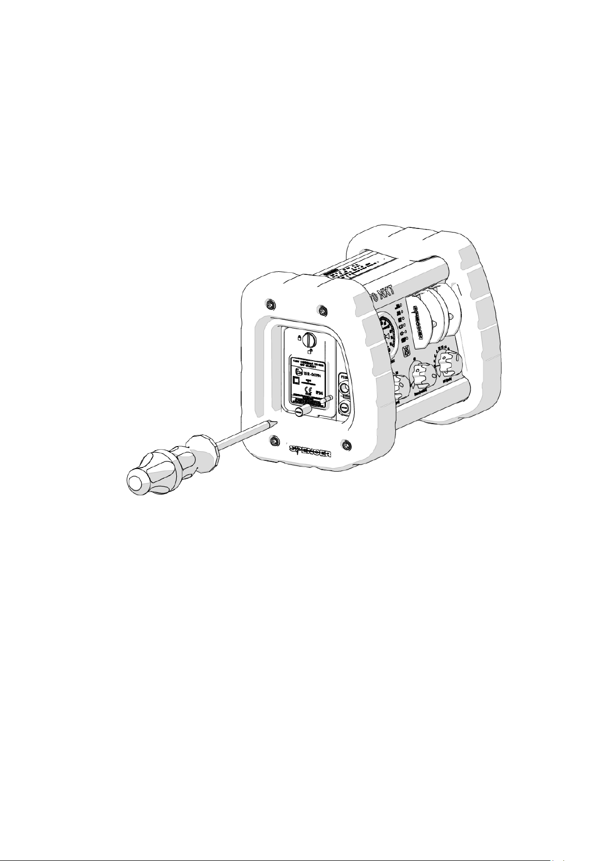
recommended to carry out separate storage in an environment with a temperature between -20°C and +35°C. After storage, the battery
needs to be recharged.
12.2.3 Fuse replacement
Spencer 170 uses two fuses type F1L250V (Fusibile Fast 5x20mm 1A). The manufacturer assumes no liability related to the use of spare
parts not meeting the specifications provided.
The fuse is a protection mean for the device, which interrupts the flow of current to the ventilator if it exceeds the maximum value
acceptable the device.
If the fuse blows, the device will continue to work with the internal power supply (battery) until it is exhausted, but will not be possible to
recharge it or use it by connecting to an external power source.
If the interruption involves the internal battery, the device can be used only if connected to the external power source.
This condition will be identified by the informations described for the event “Primary battery failure”.
Both fuses are placed on the side panel of the device and can be replaced with a screw driver removing the fuse holder.
Verify that the filament is actually broken in order to ensure that the problem is not to be found in other components.
Insert the new fuse in the removable fuse holder and screw again.
Both fuses must be replaced every year.
12.2.4 Battery replacement
The annual maintenance of the device requires, among other activities provided by the manufacturer, the replacement of all batteries.
If is necessary to replace the batteries before the annual revision, follow these instructions:
Verify that the device is turned off and disconnected from the power supply.
Using a coin or a screwdriver, open the battery compartment.
Pull out the battery pack and disconnect the connector by lifting the locking tab.
Similarly, disconnect the 9V battery from its connector.
Connect the new batteries and place them inside the battery compartment and close the cover.
The backup battery is the type 6LF22 or 6LR61 9V commercially available. Its proper connection is ensured by the connector allowin a
single way of insertion.
12.2.5 Alarms functionality test
Alarms must be subjected to regular checks to ensure that the device is suitable for use.
High pressure alarm Test 1:
Connect the device to the pneumatic supply.
Set the minute volume at the lower value
Set the pressure limit at 30 mbar
Set the frequency higher than 25 bpm
Turn on the device
Close with one hand the port used to connect the breathing tube making sure it is completely obstructed.
Gradually increase the volume minute until the alarm is activated. When the alarm starts the pointer of the manovacuometer should show
a pressure level of 25 mbar. If the alarm is regularly activated the test is successful.
20
Page 21

High pressure alarm Test 2:
To check
Required result
RESPIRATORY SYSTEM
Corrugated Tube
Non-rebreathing valve
PEEP valve (if present)
Face mask
Ventilation test
Disposable filter
Connection
All components have to be in good
conditions and correctly connected
The device or its components must be
correctly cleaned or replaced.
ELECTRIC POWER SUPPLY
Turn on the device by putting the lever on
“I”
The device is working
PNEUMATIC POWER SUPPLY
Pressure reducer and oxygen tank.
Connection between the oxygen tube and the
device input
Presence of unified plug for connection to the
gas supply or correct connection to the
pressure reducer of the tank
The pressure regulator must be subjected to
periodic maintenance and the oxygen tanks
must have enough autonomy to ensure the
proper operation of the device.
The connection to the output of the pressure
reducer is safe
There are no active alarms
Connect the device to the pneumatic supply.
Set the minute volume at the lower value
Set the pressure limit at 60 mbar
Set the frequency lower than 20 bpm
Turn on the device
Close with one hand the port used to connect the breathing tube making sure it is completely obstructed.
Gradually increase the volume minute until the alarm is activated. When the alarm starts the pointer of the manovacuometer should show
a pressure level of 60 mbar. If the alarm is regularly activated the test is successful.
Pneumatic supply alarm Test:
Disconnect the device from the pneumatic supply source or close the oxygen bottle valve.
Turn on the device.
If the alarm is regularly activated the test is successful.
Low battery alarm Test:
To perform this test is necessary to put the device out of service.
Use the device until the activation of the alarm signal.
If the alarm is regularly activated, the test was successful.
Warning: Don’t perform this test if is expected that the device is to be used because its battery charge level would be insufficient to ensure
patient safety.
In the event of prolonged inactivity periods or before transports, do the following:
Turn off the device.
Disconnect the ventilator from the power supply.
Check the charge status of the internal battery and, if necessary, recharge it.
For prolonged inactivity, in addition to the recommendations listed above, the device must be store following other precautions about the
place, time and modality of storage:
Store the device in a closed place.
Protect it from shocks and stresses
Protect it from humidity and wide temperature excursions.
Avoid contact with corrosive substances.
The procedures listed below shall be carried out and checked before each use of the device.
Le verifiche di seguito descritte devono essere effettuate prima di ogni utilizzo dell’apparecchio.
In the event of external power supply failure, is possible to use the device powered by the internal power supply. In this case is necessary to
carry out proper checks to the external power supply. This operation should be done by the installer.
If the failure involves the internal power supply, is possible to use the device powered by the external power source. Is necessary to replace
the internal battery and the fuses as soon as possible.
In the event of failure of the pneumatic supply, is necessary to switch to another ventilation equipment.
Always check that at least one alternative artificial ventilation equipment, so the rescue procedures can be carried out also if any failure
occurs.
The proper operation of the pneumatic supplies must always be guaranteed. Carefully follow the instructions and carry out the maintenance
required by manufacturers of such devices.
The inspection frequency is determined by factors such as legal requirements, the type of use, frequency of use, environmental conditions
during use and storage.
21
Page 22

Please note that you must do the cleaning as described in this manual and verify functionality before and after each use. Spencer Italia S.r.l.
declines any responsibility for the improper functioning or damages caused to the patient or user by the use of devices not subject to routine
maintenance and will void the warranty and the compliance to the Medical Device Directive 93/42/CEE.
Use only accessories/original spare parts approved by Spencer Italia S.r.l., otherwise we will accept no responsibility for the incorrect
functioning and/or damage caused by the use of any device which has not been repaired, or certified on expiry date by the manufacturer or
by one of the manufacturer's authorised service centres. Warranty will be considered void in compliance with the Medical Device Directive
93/42/EEC.
12.3 Periodic maintenance
The device must be serviced by the manufacturer or by an authorised centre every year.
If the correct revision is not carried out, the CE branding will no longer be considered valid as the product will no longer be compliant with
the 93/42/CE Directive for Medical Devices and consequently it is no longer compliant with the safety standards declared by the
manufacturer at time of purchase.
Spencer Italia S.r.l. will take no responsibility the incorrect functioning or any damage caused by a device that has not undergone regular
revision. For any operations that are not carried out directly by the manufacturer but by an authorised centre, we have to un derline that a
report regarding all operations carried out must be requested. This will permit both Spencer Italia S.r.l. and the end user to keep a log book
regarding the operations carried out on the device.
12.4 EXTRAORDINARY maintenance
Only the manufacturer or centres with written authorisation are authorised to complete any special servicing operations.
For any operations that are not carried out directly by the manufacturer but by an authorised centre, we have to underline that a report
regarding all operations carried out must be requested. This will permit both Spencer Italia S.r.l. and the end user to keep a log book
regarding the operations carried out on the device.
The final user is authorised to replace only the spare parts indicated in the paragraph 15.
12.5 Life span
The device, if used as indicated in the following instruction manual, has an average life span of 5 years
The life span can be expanded only following a general revision of the product that must be carried out by the manufacturer or by a centre
authorised by the manufacturer. Spencer Italia S.r.l. will accept no responsibility for the incorrect functioning and/or damage caused by the
use of any device which has not been repaired, or certified on expiry date by the manufacturer or by one of the manufacturer's authorised
service centres, making void both the guarantee and the conformity to the Medical Devices Directive 93/42/CEE.
Spencer Italia S.r.l. will take no responsibility the incorrect functioning or any damage caused by a device that has not undergone regular
revision. For any operations that are not carried out directly by the manufacturer but by an authorised centre, we have to un derline that a
report regarding all operations carried out must be requested. This will permit both Spencer Italia S.r.l. and the end user to keep a log book
regarding the operations carried out on the device.
22
Page 23

13. TROUBLESHOOTING
PROBLEM
CAUSE
SOLUTION
Medical gas alarm
The device is not connected to a medical gas
supply
Connect the device to a medical gas supply
The oxygen tank is exhausted
Replace with a new tank and prepare the old one for filling
procedures
The delivered pressure is not sufficient (less than
2,8 bar)
Verify the distribution system , or verify the performance of the
pressure reducer by the manufacturer
The patient can’t breath
The patient valve is not correctly positioned or is
damaged
Verify that the patient valve is correctly positioned or replace it
High pressure alarm
The airways are obstructed
Ensure that implants have been removed ; bronchoaspiration
has been carried out?
The corrugated tube is bent
Verify the corrugated tube
Patient is not hyperextended
Hyperextend or use Guedel or Berman cannulas
High pressure limit is set too low
Adjust the high pressure limit 10 mbar over the airway pressure
Low battery
Internal battery with an autonomy less than 30
min or 10 min if the alarm i s high priority
Recharge immediately the internal battery. If the problem
persist, replace the battery.
The low battery alarm doesn’t work
The 9V backup battery is discharged
Replace the backup battery
The manovacuometer doesn’t indicate
“0” when the ventilator is not working
The component is damaged
Put the device out of service and contact an authorized service
center
Is not possible to recharge the battery
The electrical connection is not stable
Verify the connection. If anomalies are present, contact an
authorized service center
The battery has reached its life limit
Replace the battery
The fuse is blown
Replace the fuse as described in the manual
The device is not working
Low voltage has caused the block of the
microprocessor
Verify the voltage of the power supply. Turn off the device and
turn on again. If the problem persists, contact a Service center
Turning on the device it does not start
the controlled ventilation
Failure to electrical or pneumatic supplies or a
failure of the device has occurred
Check for visual or acoustic signals as described in this manual.
If no signal is present, put immediately the device out of service
and contact and authorized service center
The quick connector for the input of the
medical gas is not stable
Quick connector damaged or worn
Put the device out of service and contact an authorized service
center
Noises occur caused by vibrations when
driving the medical vehicle
Constant stresses caused a deterioration of the
fasteners or mating surfaces
Ask your installer to check that the conditions for the
installation have been met
The device does not turn on
Anomalies of the internal electronic circuit
Put the device out of service and contact an authorized service
center
All lights are on continuously and the
sound is continuous
Software problem
Restart the device. If the problem persist or happens frequently,
put the device out of service, check the elextrical power supply
and contact the manufacturer.
Flashing of one or more lights inside the
bar used to monitor breathing phases
Internal component failure
Put the device out of service and contact an authorized service
center
ILED LOW BATT flashes every 3 seconds
with short acoustic signal
The main battery is fully discharged or damaged
Recharge the battery or replace it. If the problem persist, put
the device out of service and contact an authorized service
center.
23
Page 24
Standard equipment
EV00106A
Patient circuit
EV20008A
100cm power connection cable
Optionals
EV00102A
Pediatric patient circuit
EV60030C
EVX 30 – PEEP autoclavable with connector
EV60032C
EVX 32 – disposable PEEP VALVE with connector
RM20800A
SPENCER MASK – POLYS. AUTOCL. BLACK FACE MASK SZ.0
RM20802A
SPENCER MASK – POLYS. AUTOCL. BLACK FACE MASK SZ.2
RM20804A
SPENCER MASK – POLYS. AUTOCL. BLACK FACE MASK SZ.4
RM20805A
SPENCER MASK – POLYS. AUTOCL. BLACK FACE MASK SZ.5
RM20810B
SPENCER MASK – KIT 4 SIZES POLYS. AUTOCL. BLACK FACE MASKS
EV50104E
Wall bracket for Kompak
EV50107
10G wall bracket for Kompak
Spare Parts
RIEV001
40cm power connection cable w/lighter plug
RIEV002
100cm power connection cable w/lighter plug
RIEV003
200cm power connection cable w/lighter plug
RIEV004
250cm power connection cable w/lighter plug
RIEV005
400cm power connection cable w/lighter plug
RIEV007
Backup battery 9V
RIEV017
Battery pack Ni-Mh 1800mAh
RIEV009
25cm air connection tube for ventilator
RIEV010
100cm air connection tube for ventilator
RIEV011
60cm oxygen connection tube for ventilator
RIEV012
100cm oxygen connection tube for ventilator
RIEV013
240cm oxygen connection tube for ventilator
EV50111
KIT DISPOSABLE FILTERS LATEX FREE. (10 pz)
13.1 Modalità di rientro per riparazione
13.1 How to return for servicing
In accordance with new European regulations, Spencer Italia S.r.l. lists some key points to preserve the hygiene of the equip ment and
operators who use them. Spencer Italia S.r.l. trusts in compliance with these standards in order to ensure hygiene and health to all the
people who work to achieve quality and well-being.
Every device that will be returned to Spencer Italia S.r.l. will undergo health checks before the repair.
If Spencer Italia S.r.l. judges the instrument not suitable for repair because of visible signs of external and/or internal contamination, will
send the device to the customer with specification NOT REPAIRED, attaching a letter of explanation of the defects. Spencer Italia S.r.l. will
decide if contamination is due to a malfunction or incorrect use. If the contamination is due to a malfunction, Spencer Italia S.r.l. wil l replace
the product only in presence of a SALE RECEIPT. Spencer Italia S.r.l. does not respond for the accessories that show sign s of contamination,
then will replace the same charging material costs to the customer. For the above, the device MUST be carefully disinfected on the outer
casing with a cloth moistened with denatured alcohol or solutions containing hypochlorite and accessories immersing them in the same
disinfectant. Place it in a bag with specified equipment and accessories disinfected. Request to specify the defect in order to carry out the
repair in the shortest possible time. It therefore requires to carefully read the instructions to avoid compromising the device with
inappropriate use. It requires you to specify the kind of fault to give way to the technical Spencer Italy S.r.l to judge whether the fault falls
into the category of warranty
14. ACCESSORIES
15. SPARE PARTS
24
Page 25

16. DEMOLITION
The components of the patient circuit, when no longer suitable for use, if they haven’t been contaminated by any particular a gents, they can
be disposed of as normal solid waste, otherwise follow the current regulations for demolition.
WARNINGS FOR THE CORRECT DISPOSAL OF THE PRODUCT IN ACCORDANCE WITH EC DIRECTIVE 2012/19/EU WEEE:
At the end of his life, the product must not be disposed as household waste. Can be taken to special recycling centers provided by local
government, or return it to the dealer on purchase of a new device of the same type and used for the same functions. Dispose of the product
separately avoids possible negative consequences for the environment and human health resulting from inappropriate disposal and allows to
recover the materials in order to obtain significant savings in energy and resources. The symbol on the label indicates separate collection of
electrical and electronic equipment.
Warning: One incorrect disposal of electrical and electronic equipment could result in sanctions.
25
 Loading...