

Spellman XRV160P4000, XRV160P1800, XRV160N1800, XRV160P3000, XRV160N4000 Installation Manual
...Page 1

SPELLMAN HIGH VOLTAGE XRV SUBSYSTEM
INSTALLATION MANUAL
Page 2

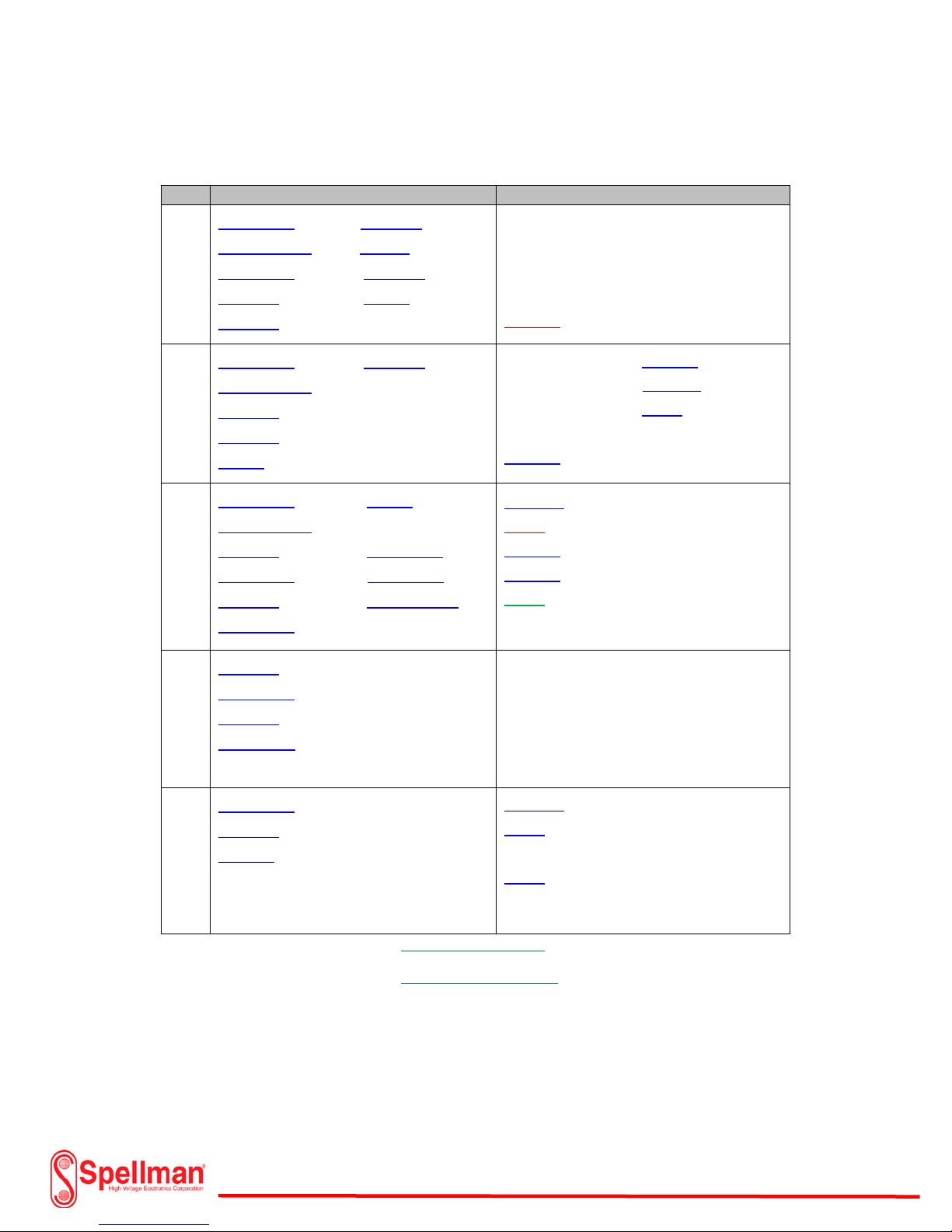
Table of Contents
General Safety ............................................................................................................................................. 4
Personal Safety ......................................................................................................................................... 4
X-Ray Tube Overview
X-ray tube data sheet ................................................................................................................................ 7
XRV Sub-system Overview ........................................................................................................................... 8
XRV 160kV Overview ............................................................................................................................... 10
XRV 225kV Overview ............................................................................................................................... 14
XRV 320kV & XRV 350kV Overview ......................................................................................................... 18
XRV 450kV Overview ............................................................................................................................... 20
I/O System Interface Box Overview ....................................................................................................... 24
XRVC Controller Overview ..................................................................................................................... 27
Coolers & Chillers Overview .................................................................................................................. 29
R24 & R28 HV Cable Overview .............................................................................................................. 31
XRV Setup & Installation ............................................................................................................................ 33
Unipolar System Diagram ....................................................................................................................... 34
Bipolar System Diagram ......................................................................................................................... 36
.................................................................................................................................. 5
Unpacking Generator ............................................................................................................................. 38
System Grounding .................................................................................................................................. 40
High Voltage Cable Installation (non-spring loaded) ............................................................................. 42
High Voltage Cable Installation (spring loaded) ..................................................................................... 48
System Grounding Detail and HV Cable Connections ............................................................................. 51
Cooler/Chiller Connections .................................................................................................................... 52
Interlock & Communication Connections (unipolar basic) ................................................................... 55
Power Connections (unipolar basic) ...................................................................................................... 60
Power Source Connections (unipolar basic) .......................................................................................... 64
Power & Feedback Connections (bipolar basic) ..................................................................................... 69
Power Connections I/O System Interface Box ........................................................................................ 70
Main Input Power Connections I/O Interface Box ................................................................................. 75
XRVC Control Box Installation ................................................................................................................ 78
118157-001 Rev C
Page 2 of 98
Page 3

Table of Contents
GUI (Graphical User Interface) Installation ........................................................................................... 81
Software Communication ...................................................................................................................... 84
X-ray Tube Filament Calibration ............................................................................................................ 87
Accessory Test Kits ................................................................................................................................. 96
XRV Sub-system Nomenclature ............................................................................................................. 97
Drawing List ............................................................................................................................................ 98
118157-001 Rev C
Page 3 of 98
Page 4
XRV Subsystem Installation Manual:
General Safety
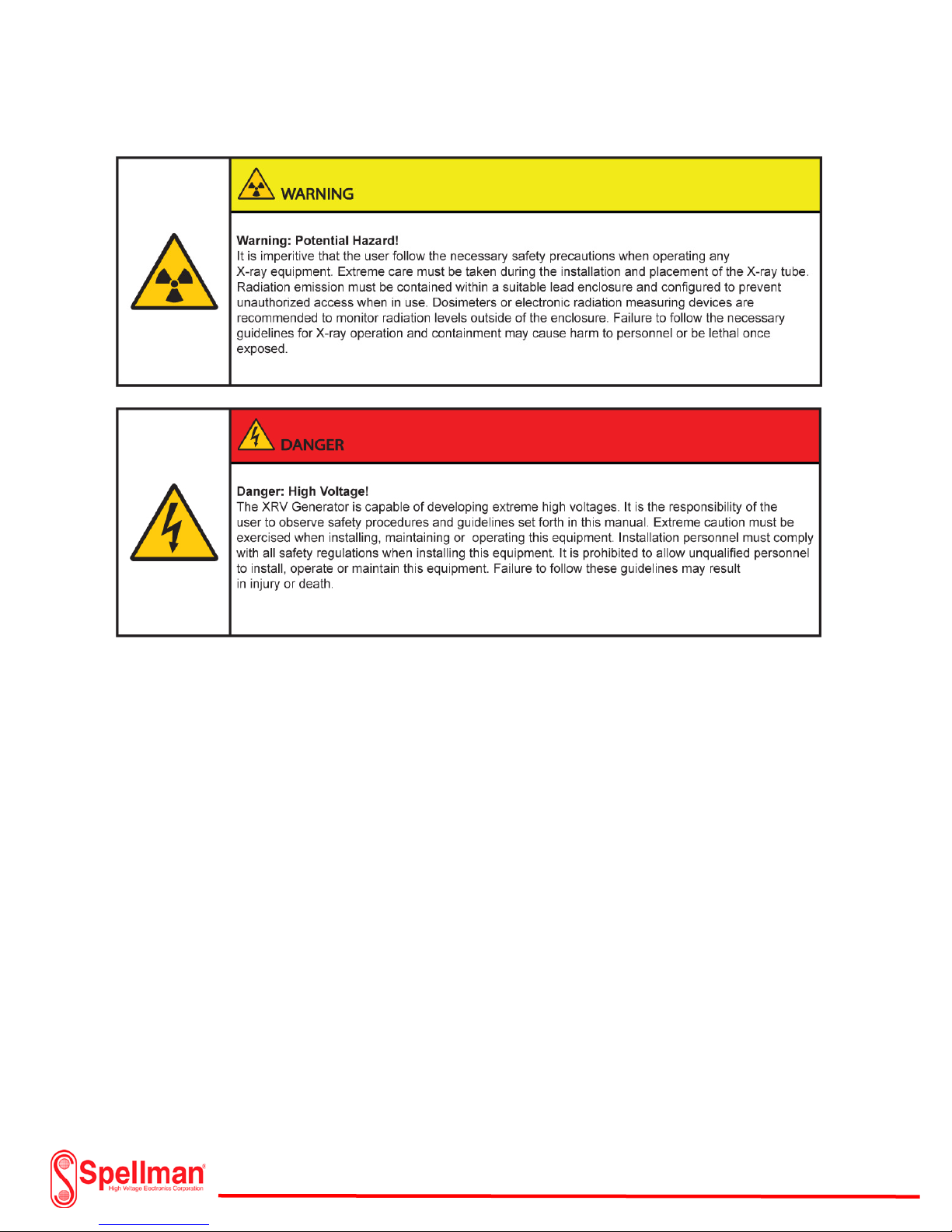
It intent of this manual to identify and safely execute the installation of the XRV Generator and
subsystem components. “Caution” and “Warning” labels used throughout this manual to highlight
critical areas of the installation and operation of this equipment. Installation, maintenance and
operation should only be handled by qualified personnel. Failure to follow these guidelines may result in
hazardous operating conditions.
Personal Safety
It is the responsibility that the individual operating this equipment do so in a safe non-hazardous
manner. Training is required on a regular basis to prevent personal injury. It is extremely important to
monitor X-ray levels applying the use of dosimeters or alternate electronic measuring devices within
normal standard guidelines. Radiation measuring equipment requires calibration on a regular basis to
prevent personal injury. Do not use this equipment in an unsafe manner or for anything other than the
intended use. Contact Spellman High Voltage regarding questions about the safe operation or
installation of this equipment.
118157-001 Rev C
Page 4 of 98
Page 5

X-Ray Tube Overview:
There are numerous X-ray tubes available depending on the user application. The tube requirement is
normally the first component selected for a specific application before any of the other subsystem
requirements. There are two basic types of x-ray tubes. One type is called a single ended or “Unipolar”
while the other is a double ended or “Bipolar”. The single ended tube only requires one high voltage
source and a filament supply in order to emit X-rays. The source voltage is usually negative with respect
to earth ground.
External cooling may be required during operation of the tube depending on the level of power output.
Single ended tubes are cooled by water circulation systems specially designed to remove heat from the
anode during operation. The circulation system consists of a water reservoir tank, pump, hoses and a
fan circulating over a radiator that is very similar to an automobile cooling system. The hoses from the
cooling system connect to the grounded side of the tube. The tube may have special fittings and will
identify the water input and output side. The flow rate and capacity of the cooling system will generally
rely on the recommendations of the tube manufacturer and operating power level. On higher power
tubes, a chiller subsystem may be required. The chiller utilizes a compressor and pump to maintain
lower water temperatures for higher wattage tubes. Both systems measure the input temperature with
respect to output temperature of the water and employ an interlock system to remove high voltage on
the X-ray tube preventing damage. Various Coolers and Chillers are available with the XRV Sub-System
and are described later in this manual.
Standard single ended tube operating voltages range from 75kV to a maximum of 225kV and may be
purchased through Spellman as part of the XRV Sub-System.
Higher voltage tubes are double-ended or “Bipolar” meaning a negative and a positive high voltage
source is required for operation. The tube operates in a similar fashion as the single ended tube with the
exception that the anode is at high voltage potential in addition to the cathode instead of being at
ground potential. Ground potential is located in the center of the tube rather than at one end. Bipolar
tubes require two X-ray generators as opposed to one.
Bipolar X-ray tubes require oil cooling as opposed to water -cooled systems. The oil serves as an
electrical insulation medium internal to the tube in addition to cooling the anode. Oil cooled systems
use a heat exchanger (oil to water) that is isolated from the oil circulation flowing through the tube. As
with water-cooled systems, the manufacturer will specify the heat removal capacity and flow rates.
These can be compared with the recommendations for X-ray tube thermal management set by the tube
manufacturer. Like the water-cooled system, these systems employ the use of thermal interlocks
terminating high voltage if the tube begins to overheat.
118157-001 Rev C
Page 5 of 98
Page 6
X-Ray Tubes:
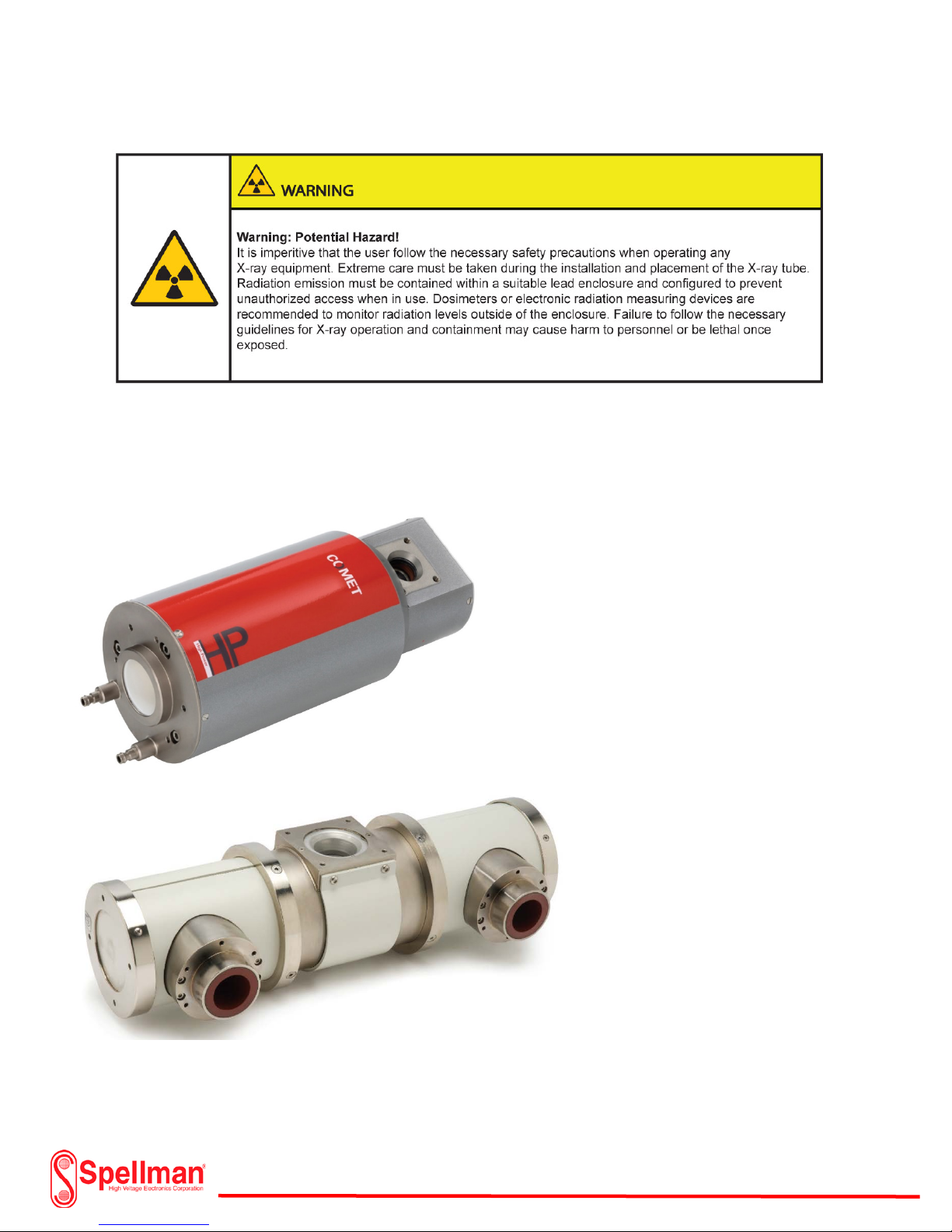
Various Unipolar or Bipolar metal ceramic X-ray tubes manufactured by Comet and Varian are available
for the XRV Subsystem. Contact Spellman High Voltage Corp. for more information.
Comet
Unipolar X-ray tube
Varian
Bipolar X-ray tube
118157-001 Rev C
Page 6 of 98
Page 7
X-Ray Tube Data Sheets:
kV
Comet
Varian
160
225
320
350
450
MXR-160HP/11 MXR-160/22
MXR-225HP/11 FB MXR-161
MXR-160HP/20 MXRP-160C
MXR-160/20 MXR-165
MXR-160/21
MXR-225HP/11 MXR-225/26
MXR-225HP/11 FB
MXR-225/21
MXR-225/22
MXR-226
MXR-320HP/11 MXR-321
MXR-320HP/11 FB
MXR-320/23 MXR-320/23AX
MXR-320/23-90 MXR-320/26AX
MXR-320/26 MXR-320HP/11AX
MXR-320/26-90
MXR-350/23
MXR-350/23-90
MXR-350/26
MXR-350/26-90
MXR-351
MXR-322
HPC-160FB NDI-160/21
HPX-160/20 NDI-160/22
HPX-160/11 NDI-161
NDI-160/01
NDI-160/20
HPC-225FB NDI-225/22
HPX-225-11 NDI-225/FB
NDI-225/01 NDI-226
NDI-225/20
NDI-225/21
HPX-320-11
NDI-320
NDI-320/23
NDI-320/26
NDI-321
NDI-350
NDI-350/23
NDI-350/26
MXR-451HP/11
MXR-451/26
MXR-452/Y
For Comet X-ray Tube Specifications: www.comet-xray.com
For Varian X-ray Tube Specifications: www.vareximaging.com
118157-001 Rev C
HPX-450-11
NDI-451
NDI-451 Be
NDI-452
Page 7 of 98
Page 8
XRV Subsystem Overview:
XRV Generator:
The XRV Generator is available in several configurations for various X-ray tube requirements. The
generators are assembled in a compact chassis allowing for a minimum amount of space required for
installation but providing for the utmost safety. Military style circular connectors for the main and
auxiliary power input offers integration flexibility and safety. Additionally, the user has the option of an
analog, com port, Ethernet or a USB connection for local or remote operation. The Ethernet connection
is extremely useful when operating the supply remotely or in the unlikely event the generator requires
evaluation by Spellman High Voltage personnel. Utilization of this feature can save the customer hours
of downtime especially when assistance is required from a long distance.
An integrated microprocessor and resistor feedback network constantly measure and adjust the output
voltage and current to provide a stable highly regulated source. Models range from 1800 watts to 6000
watts of output power. A simple to use Graphical User Interface (GUI) or selectable analog control
provides for safe operation and customer integration. The GUI software supplied with each model of the
XRV generator can be custom programmed when placing an order for specific applications. Likewise, the
analog interface allows the user to integrate unique controls and monitoring equipment. A 25 pin
subminiature “D” connector (supplied with each XRV) is standard for interlock connections and user
controls. The GUI software can also serve as a remote monitor during analog operation.
A single ended or “Unipolar” X-ray tube requires a single XRV Generator. The XRV model will depend on
the X-ray tube selected. For example, a 160kV “Unipolar” tube operating at 3 kilowatts or less would
most likely use a standard XRV model XRV-160N-3000. The output voltage of the generator would be
negative with respect to ground due to the operating specifications of the X-ray tube. Additionally, an
isolated DC supply is included to power a large or small filament connection within the X-ray tube. The
DC filament current is adjustable via the software provided or analog input selection. Specific filament
voltage and current requirements are available upon request.
Page 8 of 98
118157-001 Rev C
Page 9
XRV Generator:
A double ended or “Bipolar” X-ray tube requires two separate XRV Generators. One Generator has a
negative output with respect to ground while the other has a positive output with respect to ground.
The software provided or analog selection allows for the operation of both the positive and negative
outputs simultaneously with a minimal amount of imbalance. There are several models of the XRV
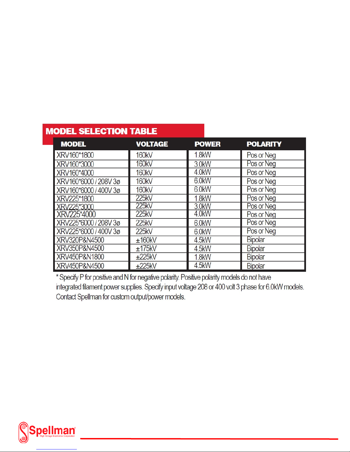
Generator available. These are listed below.
118157-001 Rev C
Page 9 of 98
Page 10
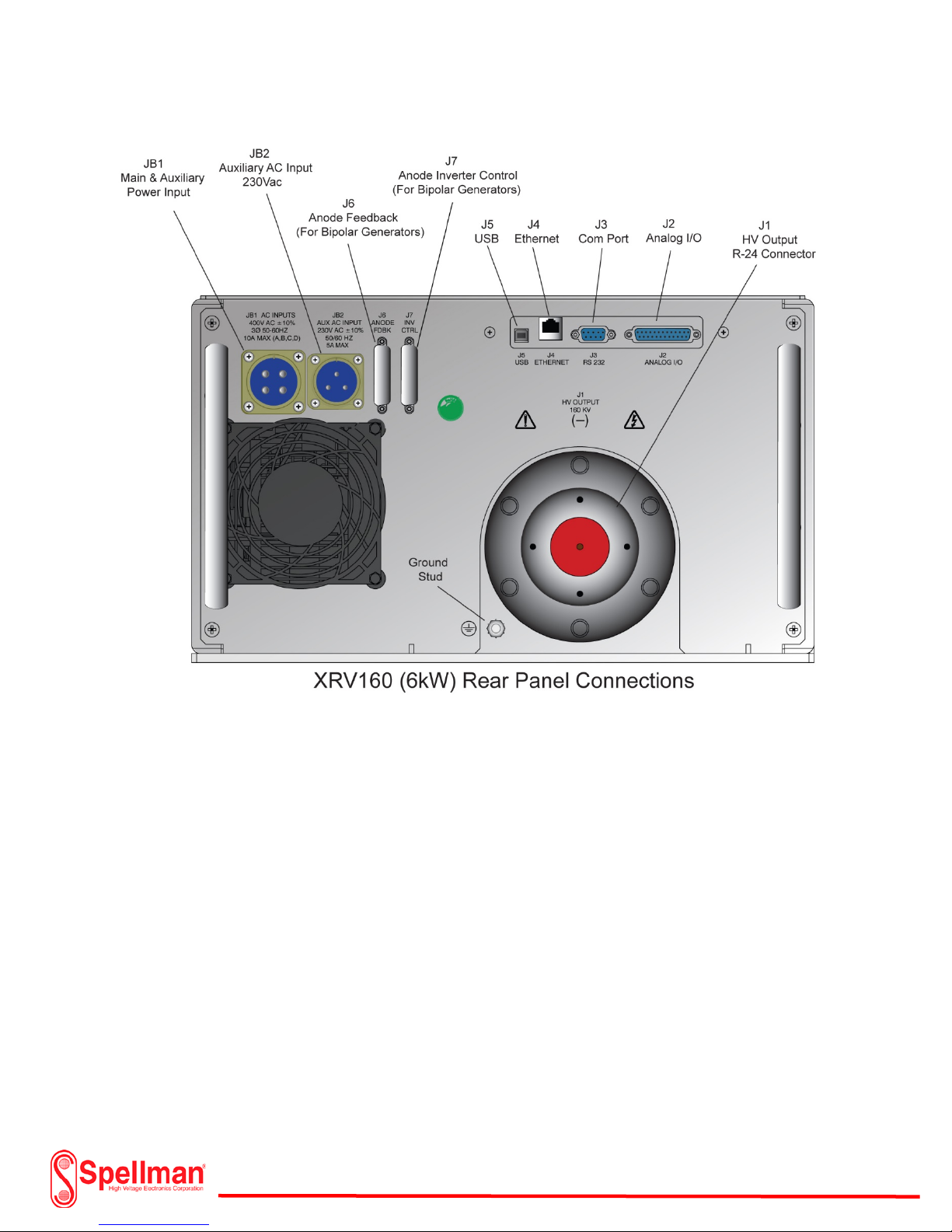
XRV 160kV Overview:
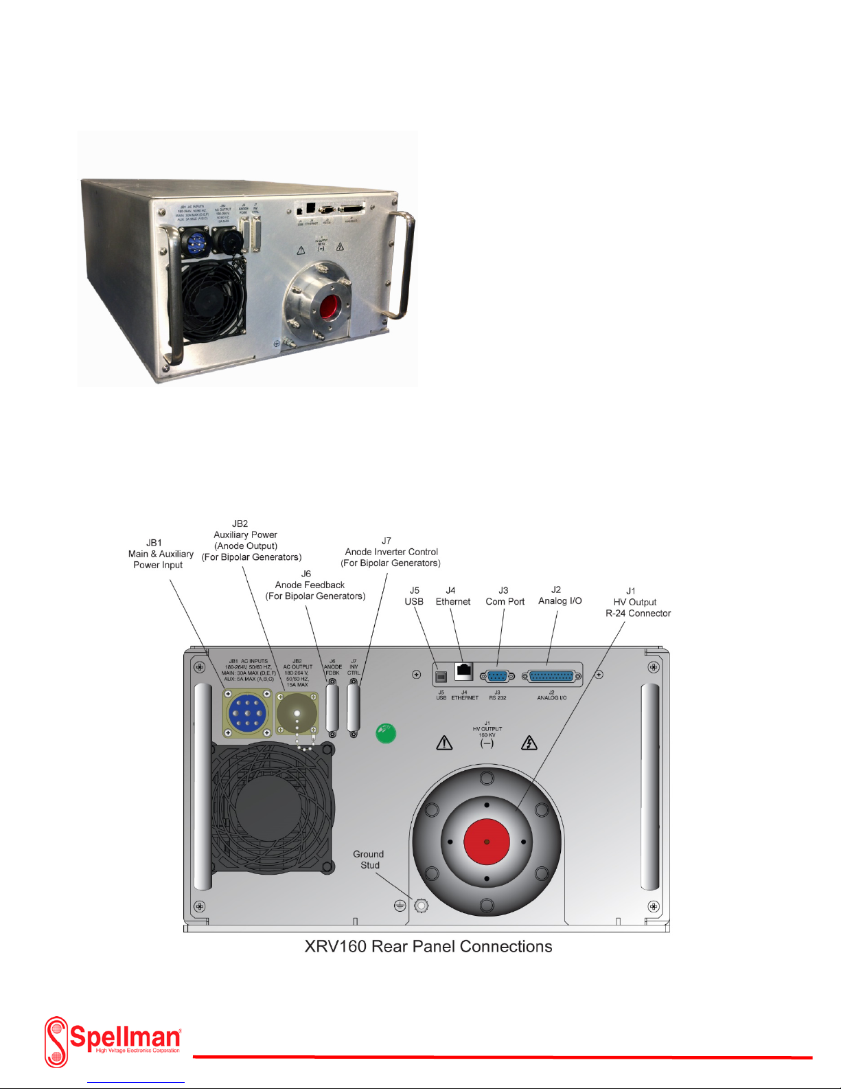
XRV160kV Rear Panel
The 160kV XRV Generator measures a compact
7.16” W x 10.09” x H 24” D (excluding handles).
The rear of the chassis has all of the necessary
connectors for power input, controls, monitoring,
and kV output. Each connector on the rear panel
is clearly marked for installation purposes. The
main and auxiliary input includes an Amphenol
style mating connector with an additional DB-25
pin connector for the I/O analog connection. The
high voltage output mates with a standard R-24
type connector. These are available from Spellman
High Voltage Corp. in different lengths and configurations for installation of the X-ray tube. Standard
Graphical User Interface (GUI) software is included with the XRV 160 Generator. A personal PC is
required for installation. The user has the option of connection to a USB, Ethernet or Com Port. The
control and monitoring of the XRV160 also includes an analog I/O connector for custom configurations.
An additional optional touch screen controller (XRVC) is also available from Spellman High Voltage Corp..
118157-001 Rev C
4kW Units
Page 10 of 98
Page 11
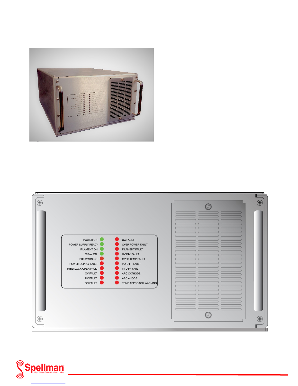
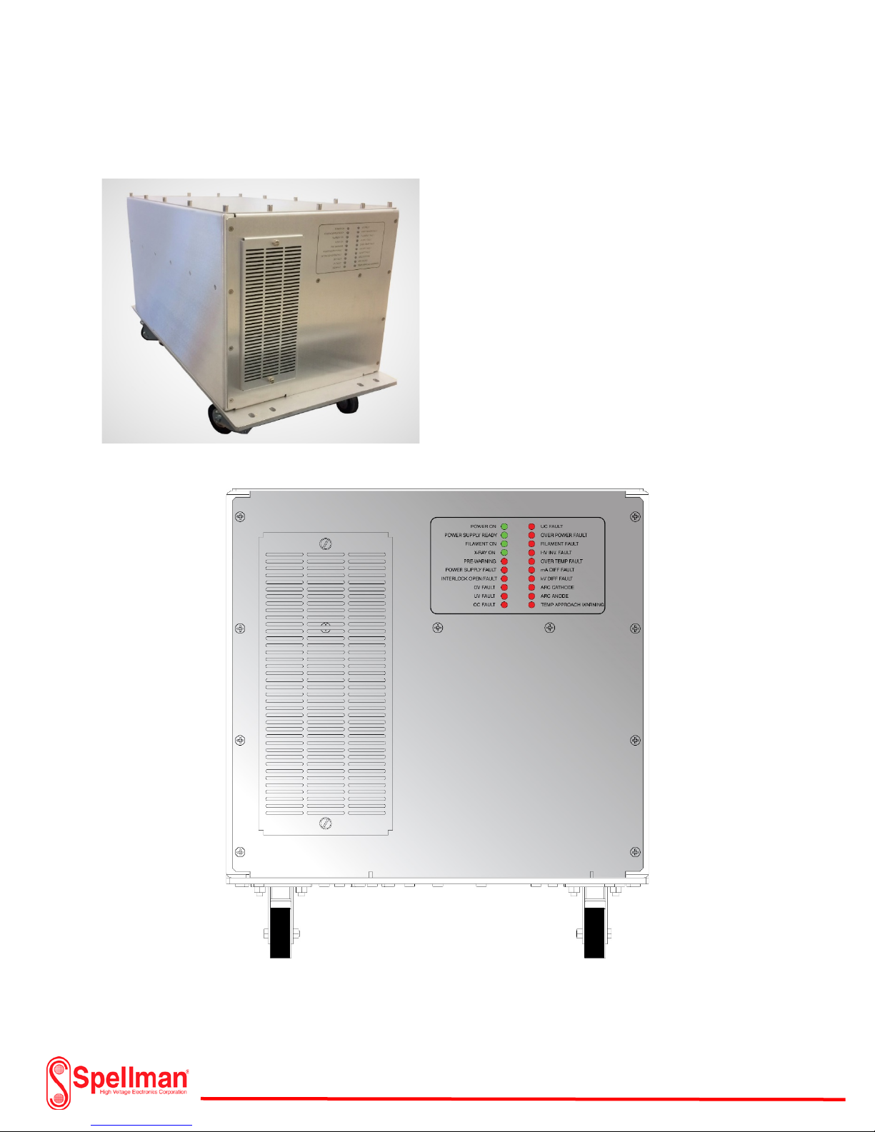
XRV 160kV Overview : XRV160 (Front Panel)
The XRV160 front panel uses LED Indicators that
show the status of the Generator. Green
Indicators signify normal operational mode
while red indicators signify a fault condition. A
fault or red indication prevents high voltage
operation. Fault conditions are “latched”
meaning that a reset must be employed before
re-starting the generator. Once the fault clears,
the red indicator will extinguish. Additionally,
fault status and ready conditions are monitored
from the I/O connector on the rear panel and
the GUI Interface software. A removable air
filter keeps dust and dirt from entering the
chassis.
XRV160 Front Panel Indicators
118157-001 Rev C
Page 11 of 98
Page 12
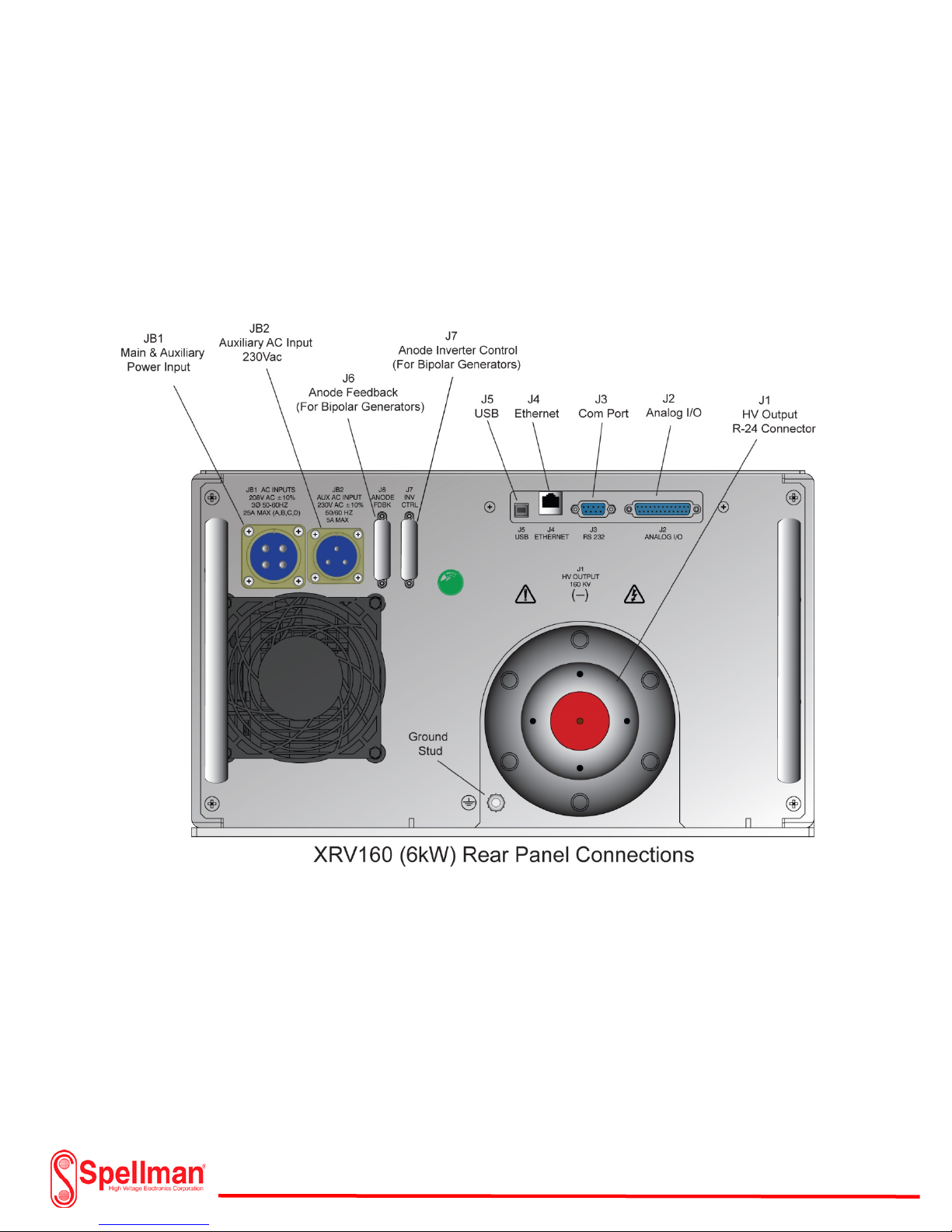
XRV 160kV Overview:
The 160kV XRV is additionally available in a 6kW version. The 6kW version uses a 208 Vac 3Ø power
input or a 400Vac 3Ø power input. The chassis overall size is the same as the 4kW version. The only
difference between the 6kW version and the 4kW version is the power input connections. Two
connectors separate the Mains from the auxiliary power input. Amphenol style power mating
connectors are included with all XRV models.
208Vac 3Ø Input
118157-001 Rev C
Page 12 of 98
Page 13
XRV 160kV Overview:
400Vac 3Ø Input
Page 13 of 98
118157-001 Rev C
Page 14
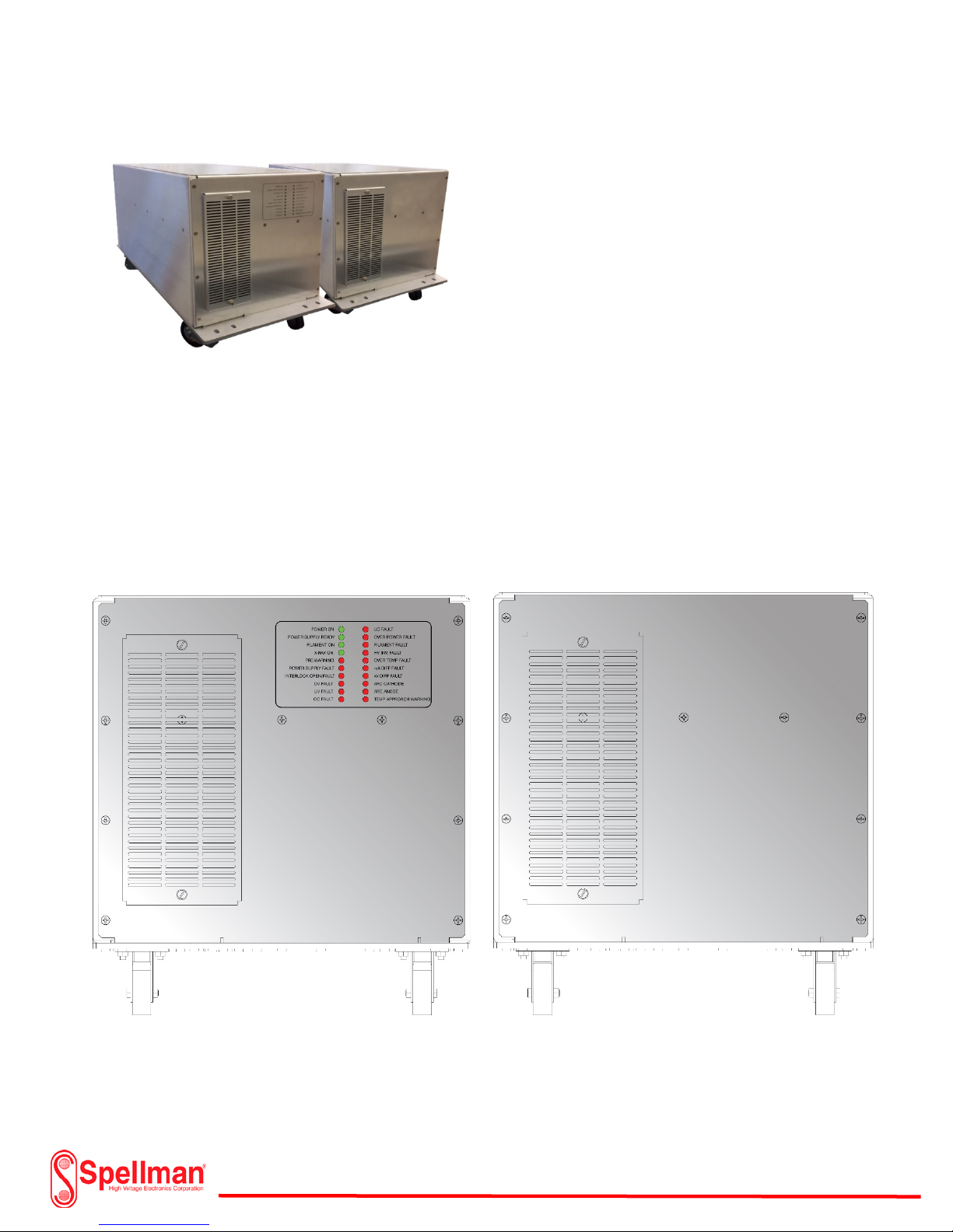
XRV225kV Overview: XRV225 (Front Panel)
The XRV225 front panel uses the same LED Indicators
as the XRV160 showing the status of the Generator.
Green Indicators signify normal operational mode
while red indicators signify a fault condition. A fault
or red indication prevents high voltage operation.
Fault conditions are “latched” meaning that a reset
must be employed before re-starting the generator.
Once the fault clears, the red indicator will
extinguish. Additionally, fault status and ready
conditions are monitored from the I/O connector on
the rear panel and the GUI Interface software. A
removable air filter keeps dust and dirt from entering
the chassis.
118157-001 Rev C
XRV225 Front Panel Indicators
Page 14 of 98
Page 15
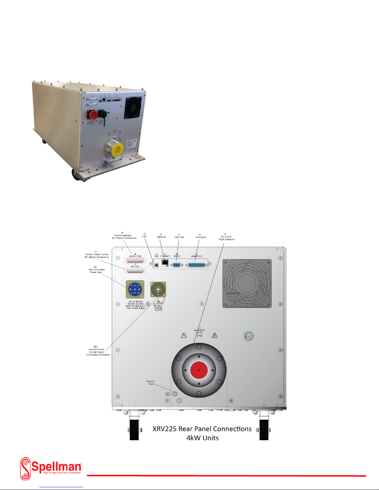
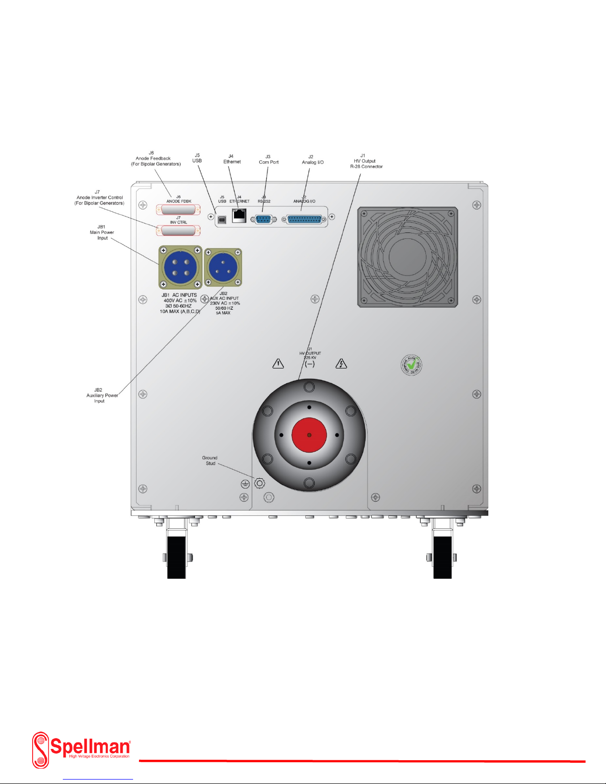
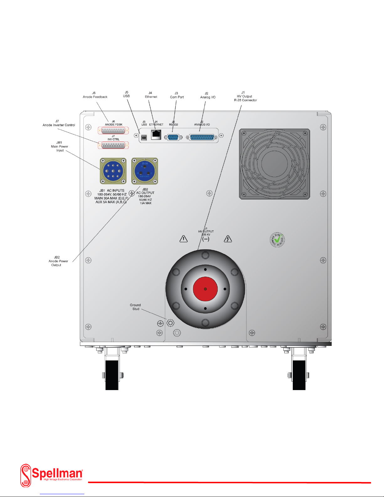
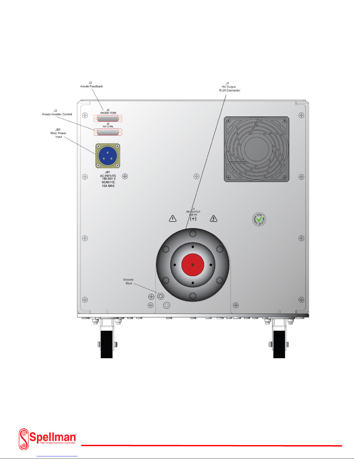
XRV225kV Overview:
XRV225kV (Rear Panel)
The 225kV XRV Generator measures a compact 17” W x
18.90” (including castors) x H 30.72” D (excluding cable
well). The assembly includes lockable castors for easy
moving. The rear of the chassis has all of the necessary
connectors for power input, controls, monitoring, and kV
output. Each connector on the rear panel clearly marked
for installation purposes. The main and auxiliary input
includes an Amphenol style mating connector with an
additional DB-25 pin connector for the I/O analog
connection. The high voltage output mates with a
standard R-28 type connector. These are available from
Spellman High Voltage Corp. in different lengths and
configurations for installation of the X-ray tube. Standard Graphical User Interface (GUI) software is
included with the XRV 225 Generator. A personal PC is required for installation. The user has the option
of connection to a USB, Ethernet or Com Port. The control and monitoring of the XRV225 also includes
an analog I/O connector for custom configurations. An additional optional touch screen controller
(XRVC) is also available from Spellman High Voltage Corp..
118157-001 Rev C
Page 15 of 98
Page 16
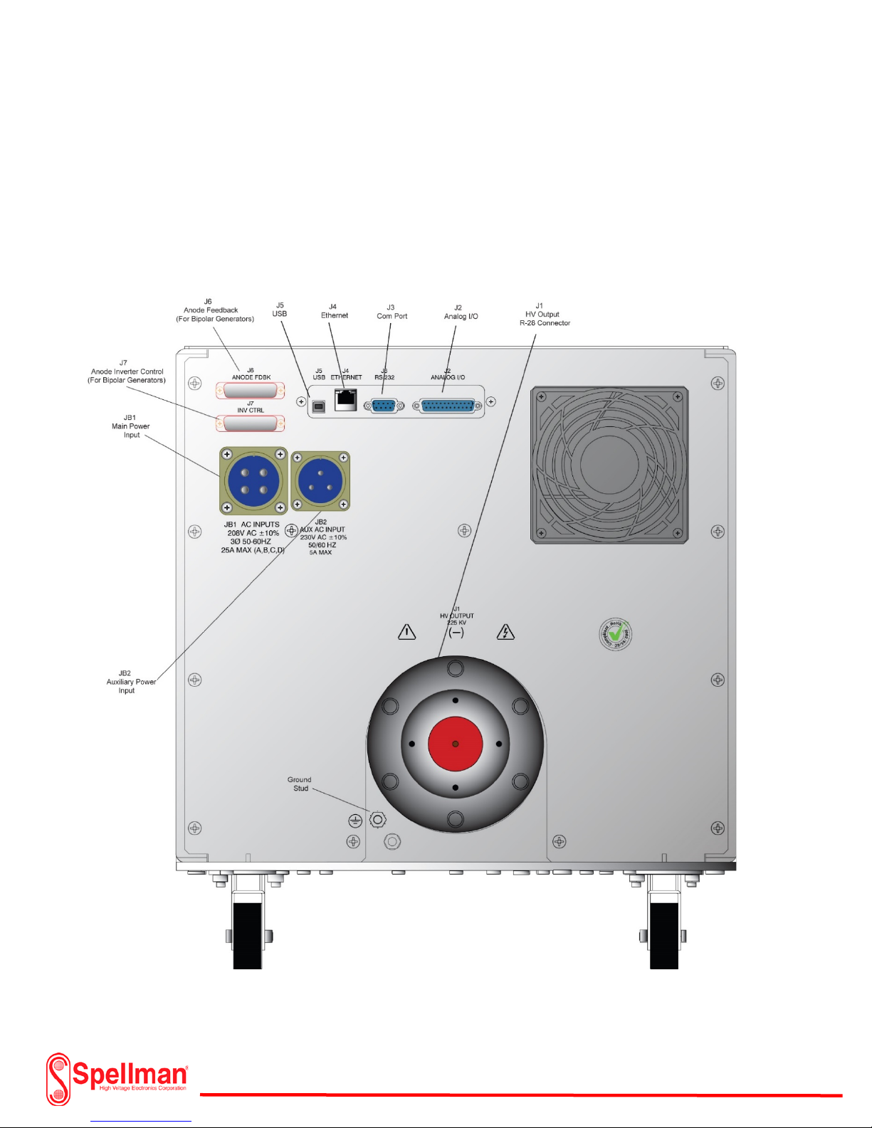
XRV225kV Overview:
The 225kV XRV is additionally available in a 6kW version. The 6kW version uses a 208 Vac 3Ø power
input or a 400Vac 3Ø power input. The chassis overall size is the same as the 4kW version. The only
difference between the 6kW version and the 4kW version is the power input connections. Two
connectors separate the Mains from the auxiliary power input. Amphenol style power mating
connectors are included with all XRV models.
XRV225kV 208Vac 3Ø 6kW Unit
118157-001 Rev C
Page 16 of 98
Page 17
XRV225kV Overview:
118157-001 Rev C
XRV225 400Vac 3Ø 6kW Unit
Page 17 of 98
Page 18
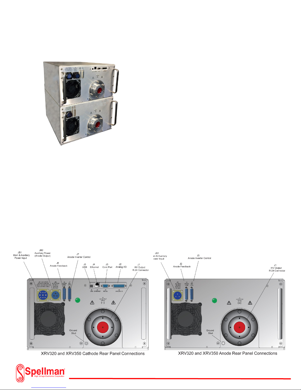
XRV320 and XRV350 Overview:
XRV320 and XRV350 (Rear Panels)
The 320kV and 350kV XRV Generators are
specifically designed to operate bipolar x-ray tubes. The
X-ray tube requires a negative kV generator (cathode)
which includes a filament supply and a positive kV
output (anode) generator. Each generator on the
320kV system has a maximum voltage of 160kV. One is
positive 160kV with respect to ground while the other is
negative 160kV with respect to ground. Likewise, the
350kV model has a maximum of 175kV each with
respect to ground. Each generator measures 7.16” W x
10.09” x H 24” D (excluding handles). The rear of the
chassis has all of the necessary connectors for power
input, controls, monitoring, and kV output. Each
connector on the rear panel is clearly marked for
installation purposes. An interconnect cable on the cathode side supplies auxiliary power to the anode
generator. Two additional 25 pin DB style cables interface the anode generator feedback and inverter
signals to the main control board residing in the cathode generator supply. The mains input on the
cathode generator includes an Amphenol style mating connector and an additional DB-25 pin connector
for the user I/O analog control. Both the cathode and anode kV outputs mate with a standard R-24 type
connector. These are available from Spellman High Voltage Corp. in different lengths and configurations
for installation of the X-ray tube. Standard Graphical User Interface (GUI) software is included with the
XRV 320 or XRV350 Generator. A personal PC is required for installation. The user has the option of
connection to a USB, Ethernet or Com Port. The control and monitoring of the XRV320 and XRV350 also
includes an analog I/O connector for custom configurations. An additional optional touch screen
controller (XRVC) is also available from Spellman High Voltage Corp
118157-001 Rev C
Page 18 of 98
Page 19
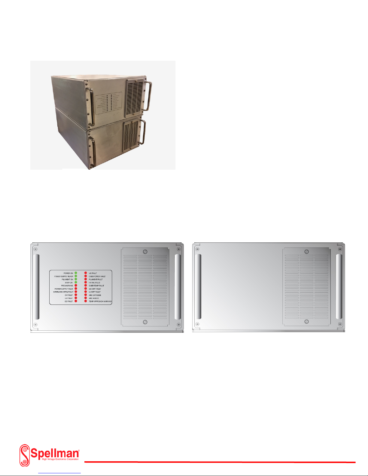
XRV320 and XRV350 Overview : XRV320 and XRV350 (Front Panels)
The cathode (negative) generator front panel of the
XRV320 and XRV350 models use the same LED
Indicators as the unipolar XRV160 showing the status
of the Generator. Green Indicators signify normal
operational mode while red indicators signify a fault
condition. A fault or red indication prevents high
voltage operation. Fault conditions are “latched”
meaning that a reset must be employed before restarting the generator. Once the fault clears, the red
indicator will extinguish. The anode (positive)
generator does not have any indicators since all of
the monitoring and fault status indicators originate
from the control board within the cathode (negative)
generator. Additionally, fault status and ready conditions are monitored from the I/O connector on the
rear panel and the GUI Interface software. A removable air filter keeps dust and dirt from entering the
chassis.
Front Panel Detail
XRV320 and XRV350 Cathode XRV320 and XRV350 Anode
118157-001 Rev C
Page 19 of 98
Page 20
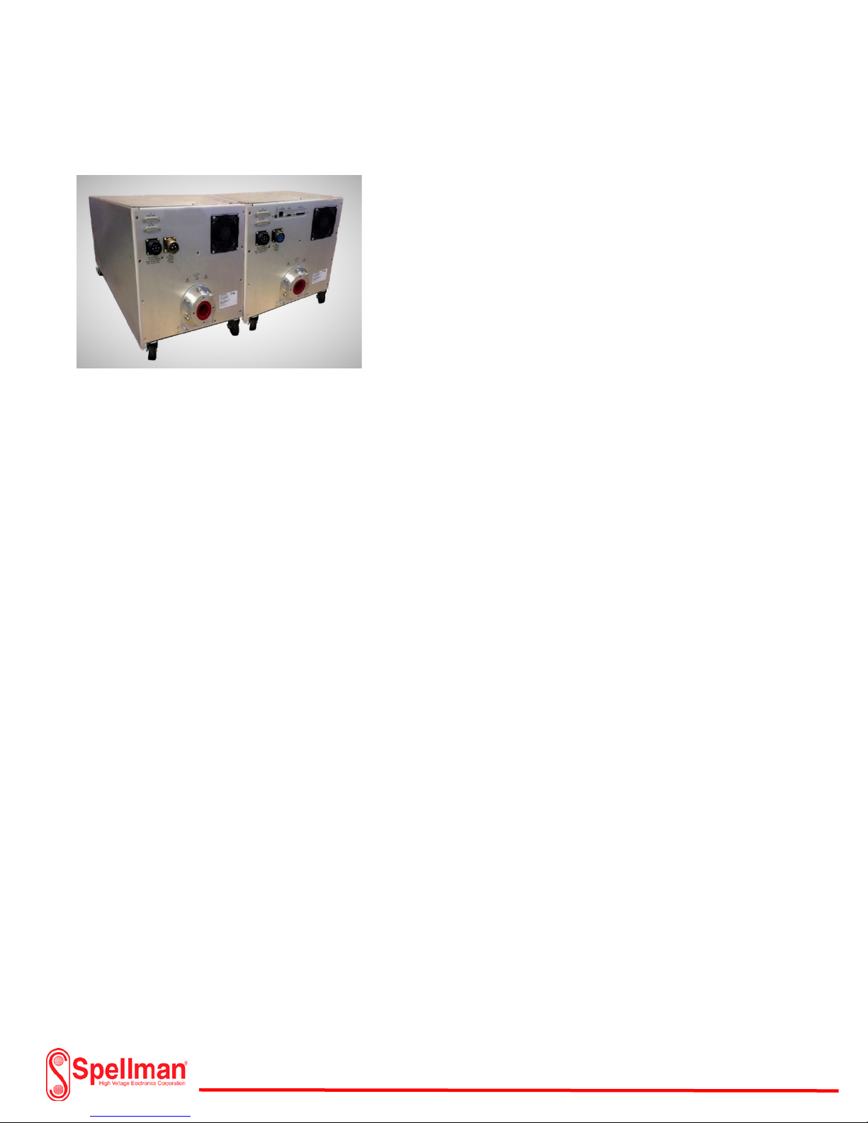
XRV450 Overview :
XRV450 (Rear Panels)
The 450kV Generator is specifically designed to operate with
bipolar x-ray tubes. The X-ray tube requires a negative kV
generator (cathode) which includes a filament supply and a
positive kV output (anode) generator. Each generator on the
450kV system has a maximum voltage of 225kV. One is
positive 225kV with respect to ground while the other is
negative 225kV with respect to ground. Each generator
measures 17” W x 18.90” (including castors) x H 30.72” D
(excluding cable well). The rear of each chassis has all of the
necessary connectors for power input, controls, monitoring,
and kV output. Each connector on the rear panel is clearly marked for installation purposes. An
interconnect cable on the cathode side supplies auxiliary power to the anode generator. Two additional
25 pin DB style cables interface the anode generator feedback and inverter signals to the main control
board residing in the cathode generator supply. The mains input on the cathode generator includes an
Amphenol style mating connector and an additional DB-25 pin connector for the user I/O analog control.
Both the cathode and anode kV outputs mate with a standard R-28 type connector. These are available
from Spellman High Voltage Corp. in different lengths and configurations for installation of the X-ray
tube. Standard Graphical User Interface (GUI) software is included with the XRV 450 Generator. A
personal PC is required for installation. The user has the option of connection to a USB, Ethernet or Com
Port. The control and monitoring of the XRV450 also includes an analog I/O connector for custom
configurations. An additional optional touch screen controller (XRVC) is also available from Spellman
High Voltage Corp..
Page 20 of 98
118157-001 Rev C
Page 21
XRV450 Overview :
118157-001 Rev C
XRV450 Bipolar Cathode Generator
Page 21 of 98
Page 22
XRV450 Overview :
118157-001 Rev C
XRV450 Bipolar Anode Generator
Page 22 of 98
Page 23
XRV450 Overview :
XRV450 (Front Panels)
The cathode (negative) generator front panel of the
XRV450 model uses the same LED Indicators as the
unipolar XRV225 showing the status of the
Generator. Green Indicators signify normal
operational mode while red indicators signify a fault
condition. A fault or red indication prevents high
voltage operation. Fault conditions are “latched”
meaning that a reset must be employed before restarting the generator. Once the fault clears, the red indicator will extinguish. The anode (positive)
generator does not have any indicators since all of the monitoring and fault status indicators originate
from the control board within the cathode (negative) generator. Additionally, fault status and ready
conditions are monitored from the I/O connector on the rear panel and the GUI Interface software. A
removable air filter keeps dust and dirt from entering the chassis.
Front Panel Detail
XRV450 Cathode XRV450 Anode
118157-001 Rev C
Page 23 of 98
Page 24

I/O System Interface Box Overview:
The XRV I/O System Interface Box provides easy
integration of the XRV Generator, XRV Touch Screen
Controller and Cooler/Chiller unit. The interface box
is enclosed in a 19” x 5.21” x 18” deep rack
mountable chassis and includes all the necessary
cables for a complete system setup and operation.
Power distribution includes a maximum 230Vac @
4kW XRV High Voltage Generator and encompasses
all the necessary X-ray safety requirements meeting
international standards. The XRV I/O Box
accommodates a variety of interface options that
are best suited for user requirements and mounting
configurations.
There are several models of the XRV I/O Box. These are capable of integrating different optional
accessories ranging from an XRV Touch Screen Controller to a “bare bones” setup allowing the user to
operate the XRV High Voltage Generator via connection to a personal PC. The user may also choose the
analog I/O interface control and monitoring as without the use of a personal PC. There are several
models of the I/O Interface Box for use with the 230Vac, 4kW XRV Generators. Other models for use
with high power Generators will be available in the near future.
XRV I/O Box Models:
118157-001 Rev C
Page 24 of 98
Page 25
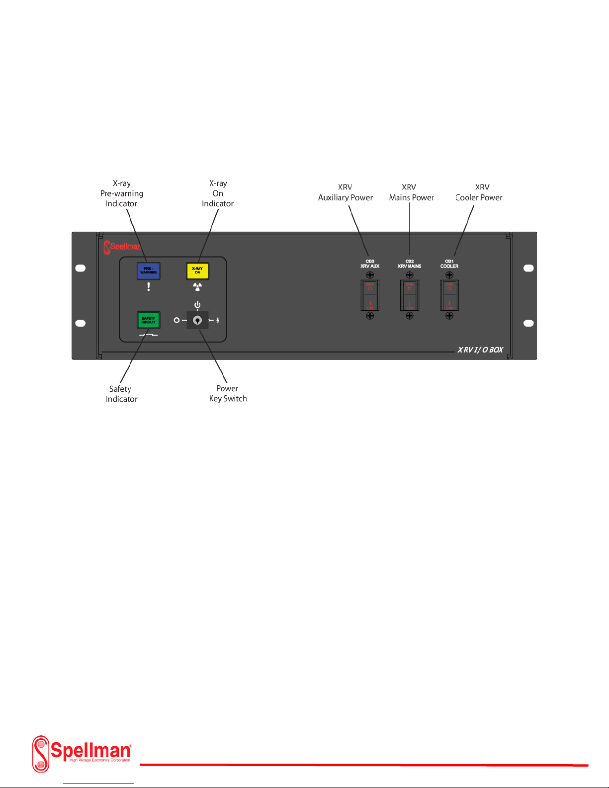
I/O System Interface Box Overview:
I/O System Interface Box Front Panel Detail
118157-001 Rev C
Page 25 of 98
Page 26
I/O System Interface Box Overview:
I/O System Interface Box Rear Panel Connections Detail
118157-001 Rev C
Page 26 of 98
Page 27
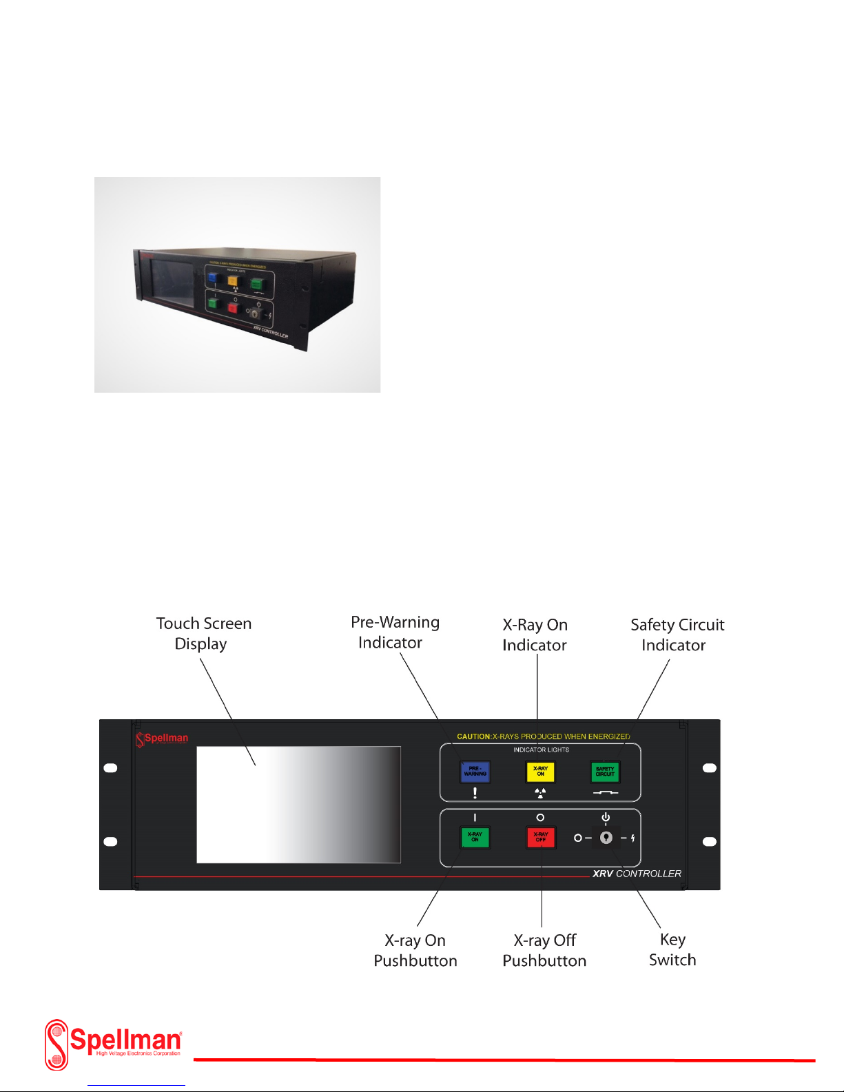
XRVC Controller Overview:
The XRVC Controller uses an embedded computing
system that runs a custom graphical use (GUI) interface
and allows the user to configure custom X-ray tube
profiles for any of the Spellman XRV series. The unit,
housed in a 19”W x 5.25” H x 13” D (ex. connectors)
features a 7” touch screen, RS-232 serial ports,
10/100/1000Mbit Ethernet and a 160GB hard drive. The
Intel Atom N270 CPU processor runs at an impressive
1.6GHz and includes 1GB of static Ram. The user has the
ability to create, save and load customized profiles for
use within the operating capabilities of the XRV
Generators. The intuitive, touch-centric, menu driven system allows ease of use with little or no learning
curve. Communication settings are stored after only one system configuration session. Parameter
settings on supported X-ray tubes may be automatically uploaded to the XRVC within the recommended
manufacturer guidelines. A comprehensive status and control screen continuously monitors
information on all critical operation parameters. An integrated on screen keyboard eliminates the need
for an external keyboard. The input voltage is 180-264Vac, 50/60Hz easily integrating with the Spellman
I/O System Interface Box.
XRVC Controller Front Panel Detail
118157-001 Rev C
Page 27 of 98
Page 28
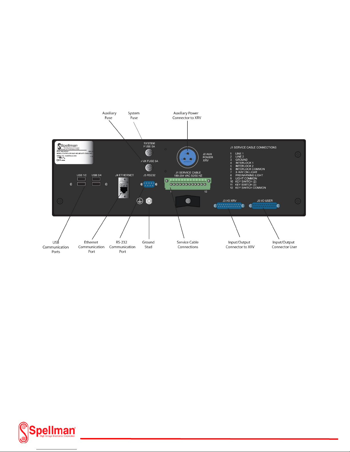
XRVC Controller Overview:
XRVC Controller Rear Panel Detail
Page 28 of 98
118157-001 Rev C
Page 29
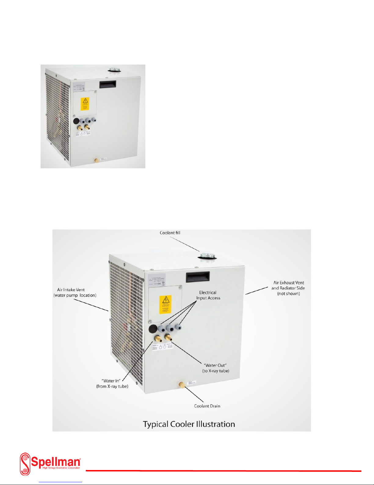
XRV Coolers and Chillers Overview:
The X-ray tube will generate a substantial amount of heat during
operation. It is important to remove as much heat as possible to
avoid damage to the X-ray tube. Various coolers remove heat
from a closed circulated water system flowing through the X-ray
tube at ground potential. The unipolar X-ray tube normally
specifies the water flow rate and ambient conditions required to
prevent damage to the tube. The capacity of the cooler to
remove heat through a water to air heat exchanger depends on
the difference between the ambient temperature and the water
outlet temperature. The coolant used could be either plain water
or a mixture of water and glycol usually specified by the
manufacturer. The inlet and outlet hose connections are specifically marked for correct flow through the
tube. A thermal switch monitors the outlet water temperature. If the outlet temperature exceeds the
recommended operating temperature, the switch will activate opening an interlock chain removing
power from the Generator. For optimal performance of the cooler, it is important not to obstruct or
restrict the air flowing through the vents. The ambient air temperature should be maintained according
to the manufacturers’ recommendations.
118157-001 Rev C
Page 29 of 98
Page 30

XRV Coolers and Chillers Overview:
Chillers may be used with either Unipolar or Bipolar X-ray tubes. The
tube power and ambient temperature will determine if a chiller is
required in order to cool the X-ray tube. Chillers are much like air
conditioners whereas a compressor lowers the temperature of the
water or oil within a closed loop system. Oil coolant is used with a
Bipolar tube since the Anode section of the X-ray tube “Floats” at
high voltage potential and an insulation medium must be used to
cool it and provide isolation to ground. An internal thermostat
maintains the temperature. It constantly compares the water/oil
that returns from the X-ray tube to the water/oil supplied to the Xray tube. If the difference is too great, the chiller will provide an
interlock signal (usually a dry contact switch) to shut down the high
voltage generator and prevent any damage to the X-ray tube.
Adequate clearance is necessary when installing a chiller to allow the
flow of air through the venting system.
118157-001 Rev C
Page 30 of 98
Page 31

XRV R24 and R28 HV Cables Overview:
The X-ray tube and the XRV Generator uses a specific type of
receptacle for the high voltage connection. The receptacles
mate with an R24 or R28 high voltage cable. The R24 Cable is for
systems with an output voltage of 160kV or less while the R28
Cable are designed for systems with voltages as high as 225kV.
The conical shaped cable plugs ,designed to reduce voltage
stress on the connections use silicone grease to fill any air voids
and avoid high voltage arcing. The cables are available in
various lengths, straight or right angle spring and non-spring
loaded connectors. Flanges are specially designed to apply the
right amount of contact force and keep the connector securely in place. A special gapping tool adjusts
the flange to cable well spacing making sure the male conical connector is the correct length for the
cable well depth. Typical Cables and Flanges are shown below.
Spring Loaded R24 and R28 Type Cables
118157-001 Rev C
Page 31 of 98
Page 32

XRV R24 and R28 HV Cables Overview:
Standard Type R24 and R28 Type Cables
R24 and R28 Type Cable Flanges
118157-001 Rev C
Page 32 of 98
Page 33
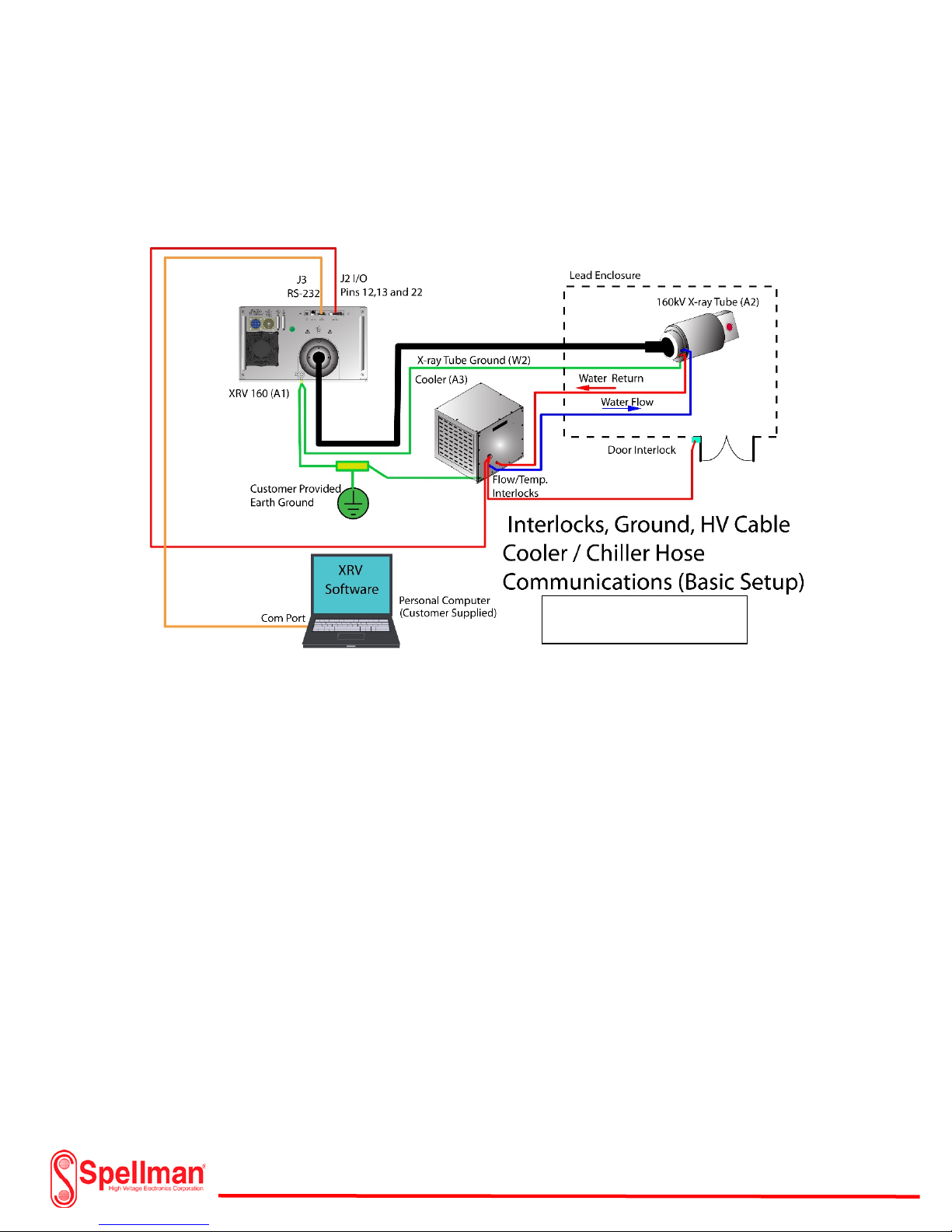
XRV Setup and Installation:
There are several installation configurations available for the XRV Subsystem. The most economical
system employs the use of a single ended X-ray tube, the XRV Generator, Personal PC, X-ray Cable, Input
Power / Communication Cables and Water Cooler/ Chiller. The XRV Generator includes ready to install
software that can be loaded into the user’s personal PC. A minimal setup for a standard Unipolar
subsystem is illustrated on the following page. The user must provide a personal PC for installing the
included software or elect to interface their own controls via the I/O from J2 (25 Pin subminiature D
connector) on the rear of the XRV Generator. Information regarding the I/O connector will be covered
later in this manual. It is imperative the installer follow all safety regulations and codes for installing this
equipment. Details such as input power requirements, wire sizing, and physical placement of each
component is critical for safe and trouble free operation. Do not install power wires or high voltage
cables in high traffic areas where they could be damaged by heavy equipment. Wire lengths should be
considered for voltage drops and thermal management. The X-ray tube
118157-001 Rev C
Page 33 of 98
Page 34

XRV Unipolar System Diagram
Typical Unipolar System (Minimal Requirements)
118157-001 Rev C
Page 34 of 98
Page 35

XRV Unipolar System Diagram
Typical Unipolar System with Additional Controller and I/O Box
118157-001 Rev C
Page 35 of 98
Page 36

XRV Bipolar System Diagram
Typical Bipolar System (Minimal Requirements)
Page 36 of 98
118157-001 Rev C
Page 37

XRV Bipolar System Diagram
Typical Bipolar System with Additional Controller and I/O Box
118157-001 Rev C
Page 37 of 98
Page 38

Unpacking Generator:
Loosen 6 Bolts on Bottom
of Generator Crate
XRV 160
Generator Crate
XRV 160 Generator
Lift Generator
from Handles
The XRV Generator and subsystem components are shipped in padded containers to avoid damage
during shipment. All of the containers will have an indication that shows the correct orientation for
shipment and unpacking. The XRV Generator is surrounded within a foam padding to protect it from
shock and vibration during shipment. There are 6 bolts on the surrounding bottom of the crate that
need to be loosened in order to remove the XRV Generator. Do not remove the 4 bolts from the top of
the crate. Once the bolts are loosened, the top can be removed. Two people can lift the top of the crate
evenly from either end or a hoist and strap may be used instead. Visually inspect the XRV Generator for
any signs of damage once the top is removed. Report any damage to Spellman High Voltage. Include any
photos and a verbal description. The crate should not be exposed to moisture or extreme temperatures.
118157-001 Rev C
Page 38 of 98
Page 39

P/N 105808-434 Conn.
P/N 105808-654 (4) Pin Conn. (6kW)
P/N 203373-001 25 Pin
Subminiature D
P/N SWD0026-009
Software
P/N 304747-001
(Bipolar XRV Only)
P/N PNC4002A
(Bipolar XRV Only)
P/N PNC4002A
(Bipolar XRV Only)
Unpacking Generator:
In addition to the XRV Generator, there will be several accessories. The 4kw unipolar models include a
CD/DVD program setup, Interlock bypass subminiature D connector and a Main Power Connector. The
6kW unipolar generator includes an additional Auxiliary Power Connector. The 4kW bipolar generator
includes an interconnect power cable and 2 additional subminiature D cables for the feedback and
inverter control for the additional positive polarity generator. Additional subsystem components such as
the X-ray tube, Cooler/Chiller
P/N 105808-440 Clamp
P/N 105808-440 Clamp
P/N 105808-441 (3) Pin Conn. (6Kw)
P/N 105808-440 Clamp
118157-001 Rev C
Page 39 of 98
Page 40

XRV Generator Installation:
General:
Locate the XRV Generator in an area where there is limited access and in close proximity to the X-ray
tube load. The Generator must have adequate clearance for the intake air filter and exhaust fan. Make
sure the area is a dry and dust free location. The X-ray tube load must be located within an interlocked
secure lead shielded enclosure that prevents unauthorized access when in use. Typical distances from
the X-ray tube to the Generator range from 5 meters to 20 meters depending on the length of the high
voltage cable. Installation and maintenance of the high voltage cable is extremely important to prevent
damage to both the X-ray tube and XRV Generator cable sockets. Locate the high voltage cables away
from high traffic areas and the input power cables. Use a minimum of #10 copper grounding wire and
#10 ring lugs when grounding any of the subsystem components. Make sure to use the proper crimping
tool for the ring lug used. Keep the ground distances as short as possible from the XRV Generator and
earth ground. Review the label on the rear of the XRV Generator to for the correct installation of the
input voltage. Incorrect input voltage will damage the XRV Generator.
System Grounding:
All of the subsystem components are required to be connected earth ground. Install all of the
system components in the desired location. Cabling should be as short as possible Use a minimum of
#10 AWG insulated copper stranded wire for the XRV Generator, X-ray tube, cooler/chiller, I/O Box and
Controller. Strip and crimp the wire on to a #10 Ring Lug using the proper crimping tool. Ensure that the
crimp is tight and does not pull out of the lug. Remove the ground connection nut from the X-ray tube
and place the ring lug over the threaded connection. Replace the nut and torque to the manufacturer’s
specification. Connect the opposite end of the wire to the rear panel ground of the XRV Generator
118157-001 Rev C
Page 40 of 98
Page 41

System Grounding:
ground. Strip and crimp #10 ring lugs on another #10 AWG wire to connect from the XRV generator to
earth ground. Keep this wire as short as possible.
If the Generator is a bipolar model, a ground wire with lugs (supplied) connect between the Anode
(Positive Generator) and the Cathode (Negative Generator) chassis ground. If the system includes the
I/O Subsystem Box and the Controller, connect the Controller ground using #10 AWG wire and
appropriate ring lugs to the I/O Subsystem. Run another ground from the I/O Subsystem Box ground lug
to earth ground. The grounding system should look like the following diagram for a unipolar system.
Page 41 of 98
118157-001 Rev C
Page 42

High Voltage Cable Installation:
General:
Two types of high voltage cable connectors used for connecting the XRV Generator to the X-ray tube.
They are either spring-loaded or non-spring loaded. The maximum high voltage for the XRV generator
and X-ray tube dictates either an R-24 or R-28 type cable. An R-24 high voltage cable is used on the
160kV XRV Generator while the R-28 is used on the 225kV models. The X-ray tube specifies what type of
cable plug it requires. Spring-loaded connectors are the preferred choice since they are adjusted for the
right amount of force when connecting to the receptacle. Gapping tools measure the correct spacing of
the flange when inserting the plug into the high voltage receptacle. Non-spring loaded cables are still
used but require increased maintenance and special attention when installing.
Non-spring loaded cable installation:
Several steps are required when installing a non-spring loaded high voltage cable.
The first step is to ensure that the cable plugs and receptacles are free from dirt
or damage that could cause high voltage breakdown. It is important to clean
both the cable plug and receptacle prior to installation. While wearing nitrile
powder free examination gloves, use a clean lint free cloth such as Kimtech Science Delicate Task Wipes,
remove any dust or dirt from the cable plug and cable receptacle.
Lint Free Wipes Nitrile Gloves Dow Corning #4 Silicone Compound
118157-001 Rev C
Page 42 of 98
Page 43

Cleaning Cable Plug:
Wipe cable end with
Apply 2 beads of
Spread compound
Remove compound
While supporting the cable with one hand, apply a small bead of the Dow Corning #4 silicone compound
to opposite sides of the cable plug to opposite sides of the cable plug. Spread the compound with your
finger evenly over the entire rubber cone surface of the plug. Using another clean lint free wipe, remove
the applied silicone from the cable plug. Do not use alcohol to clean the cable plug, as this will dry out
the rubber cone. Repeat for the opposite side and place in a clean area.
dry lint free cloth
evenly with finger
silicone compound
with new cloth
118157-001 Rev C
Page 43 of 98
Page 44

Cable Receptacle Cleaning:
Obtain a foam
Wrap a lint free clean
Insert into HV
Remove and
Inspect the cable receptacle in both the XRV Generator and X-ray tube for any dirt or foreign debris.
Wrap a lint free cloth around a “foam” glass cleaning brush and insert gently into the cable receptacle.
The foam brush should have 1/8” clearance on the inner circumference of the cable receptacle. While
holding the cloth, rotate the foam brush several times and remove from the receptacle. Inspect the
receptacle for debris. Repeat if necessary.
glass cleaning brush
cloth around foam brush
receptacle and rotate
discard cloth
118157-001 Rev C
Page 44 of 98
Page 45

Non-spring loaded HV cable installation:
Obtain flange
Place flange over
Thread flange on
Gapping tool for
Insert dry HV cable
Measure distance
High Voltage Cable Installation (X-ray Tube):
Wear nitrile gloves and obtain an X-ray tube cable flange. Wipe the flange with a lint free cloth and place
over a clean high voltage cable plug. (One cable flange will fit the X-ray tube and the other will fit the
XRV Generator). Rotate the flange counter clockwise on to the cable threads until it stops. Do not cross
thread the assembly. Insert the clean dry connector into the high voltage cable receptacle of the X-ray
tube with a small amount of force. Adjust the cable flange by rotating it clockwise until the flange is
approximately 1/2 inch from the X-ray tube mounting surface. Insert the gapping tool (5.5m – 6mm)
between the tube mounting surface and the flange. Rotate the flange until it is snug against the gapping
tool. Remove the gapping tool and rotate the flange slightly to align the mounting holes with the x-ray
tube holes. Tighten the grub screws of the cable flange to prevent any further rotation and remove the
plug from the receptacle. Apply 2 thin beads on opposite sides of the rubber cone. Distribute a thin coat
of silicone evenly on the entire cone. Finish the distribution by spreading in a circular fashion around the
circumference of the cone. Do not apply any silicone to the metal tip. If the silicone gets on the metal
tip, use a clean dry lint free cloth to remove it. Insert the HV cable plug into the receptacle until it seats
properly. Use the correct hardware and torque as per manufacturer specifications to tighten the cable
flange screws, alternating between the opposite placed screws.
and HV cable
R24 & R28 Cable
118157-001 Rev C
cable plug
plug into X-ray tube
Page 45 of 98
cable plug
with gapping tool
Page 46

High Voltage Cable Installation (X-ray Tube):
Apply 2 beads of
Spread compound
Insert HV cable plug
Tighten grub
Tighten cable flange
screws
in tube receptacle
silicone compound
screws
evenly with finger
118157-001 Rev C
Page 46 of 98
Page 47

High Voltage Cable Installation (XRV Generator):
Insert dry HV cable
plug in XRV receptacle
Adjust flange with
gapping tool
Tighten grub
screws
Apply 2 beads of
silicone compound
Spread compound
evenly with finger
Insert HV plug in XRV &
Repeat the assembly procedure as previously described on the opposite end of the high voltage cable
plug. The only notable difference is that the gapping tool will sit flush against the high voltage cable
receptacle when adjusting the flange. The tube receptacle has a collar that the flange fits over, while the
XRV Generator flange will sit flush against the receptacle.
tighten flange screws
High Voltage
Cable Gapping
Distances:
118157-001 Rev C
Page 47 of 98
Page 48

Standard High Voltage Cable Installation Problems:
High voltage arcing and failures can result from improperly gapped standard cables. Too much force on
a cable will cause the cone to bulge and deform creating voids within the receptacle. Another issue
involves stressing the filament and common connections resulting in breakdown. Never try to reuse a
kinked or bulging cable. Over application of silicone grease will also create voids and high voltage arcing.
Spring Loaded High Voltage Cable Installation:
Clean the spring-loaded cables and high voltage receptacles prior to insertion. Refer to the cleaning
procedures in the non-spring loaded section of this manual.
Wear nitrile gloves and obtain an X-ray tube cable flange. Wipe the flange with a lint free cloth and place
over a clean spring-loaded high voltage cable plug. (One cable flange will fit the X-ray tube and the other
will fit the XRV Generator). Rotate the flange counter clockwise on to the cable threads until it stops. Do
not cross thread the assembly. Insert the clean dry connector into the high voltage cable receptacle of
the X-ray tube with a small amount of force. Make sure the contact head of the cable filly inserts while
checking the gap. Refer to the “High Voltage Cable Gapping Distances” table for the correct gap
measurement. Use a gapping tool if available. When the desired gap has been set, rotate the cable
flange slightly so that the holes line up with the receptacle holes. Tighten the grub screws on the cable
flange so that it restricts it from rotating. Remove the cable plug and apply 2 thin beads on opposite
sides of the rubber cone. Distribute a thin coat of silicone evenly on the entire cone. Finish the
distribution by spreading in a circular fashion around the circumference of the cone. Do not apply any
silicone to the metal tip. If the silicone gets on the metal tip, use a clean dry lint free cloth to remove it.
Page 48 of 98
118157-001 Rev C
Page 49

Place the connector carefully into the X-ray tube receptacle without scraping any of the silicone from
Insert dry HV cable
plug into X-ray tube
Adjust flange for
Tighten grub
screws
Tighten cable flange screws
Apply 2 beads of
silicone
Spread compound
Insert HV cable plug
Correct Gapping
the cone. Tighten the cable flange screws, alternating between the opposing placed screws.
Spring Loaded High Voltage Cable Installation:
If a cable flange with a window is used, verify the correct compression was achieved by verifying 2 rings
are visible through the cable flange window. If not, reset the gapping distance until 2 rings are visible
(approx. 5.5mm displacement). Repeat this installation for the XRV Generator side of the cable.
proper gapping
in tube receptacle
evenly with finger
118157-001 Rev C
Page 49 of 98
Page 50

Under gapped
Over gapped
Typical gapping tool for
Spring Loaded High Voltage Cable Installation:
spring loaded cables
118157-001 Rev C
Page 50 of 98
Page 51

System Grounding Detail and HV Cable Connections:
118157-001 Rev C
Page 51 of 98
Page 52

Cooler/Chiller Connections:
The X-ray tube requires cooling to prevent damage. Single ended or unipolar tubes require a water
circulation system in order to cool the tube while a double ended or bipolar x-ray tube requires a chiller
and oil cooling. Depending on the power rating for the X-ray tube, the manufacturer will recommend a
specific flow rate and the cooling medium for the tube. A typical cooler will have a water fill cap, water
drain plug, water inlet and outlet flow connections, power input connections and interlock connections.
A typical cooler is illustrated below.
In some environments it may be necessary to mix glycol with the water in order to prevent freezing
should the ambient temperature drop. Allow sufficient space for the unit when installing for air
circulation. The manufacturer normally recommends the minimum distance required and the mixture
for glycol to water for specific temperature ranges. The water outlet connection is water that flows to
the x-ray tube anode while the water inlet connection returns from the X-ray tube anode. Although the
cooler may provide temperature indicators and over temperature switches, it is important for the
correct water flow configuration from the tube to the cooler. Failure to do so may result in overheating
and tube damage. Below is a typical symbol for inlet and outlet water connections.
Various hose connections may be used for the water connections. Some are quick disconnecting while
others either use threads or hose clamps. Consult Spellman High Voltage when ordering the cooler for
more information regarding connectors. If the I/O Box is purchased with the sub-system, a circuit
breaker will be provided for the cooler. If the I/O Box is not a part of the sub-system, then the user will
be responsible for the correct breaker installation. Typically a cooler will require a 7.5 Amp. double pole
breaker. Consult Spellman High Voltage for sizing the breaker.
118157-001 Rev C
Page 52 of 98
Page 53

Ball Type
Internal Cooler
Internal Cooler
Cooler/Chiller Connections:
The cooler may or may not include a water flow indicator. Typically, water flow may be rated in liters
per minute or gallons per minute depending on the tube size and specifications. It is important to check
the water flow with a meter to ensure the tube has adequate cooling. Digital or traditional ball type
meters may be permanently installed for verification. An internal flow and over temperature switch is
provided with a dry set of contacts that can be integrated with the XRV Generator that will turn off the
high voltage if the water flow is insufficient or temperature is too high.
Flow Meter
Flow Switch
Temperature Switch
The bipolar tube uses oil since the anode is at high voltage potential and must be isolated from ground.
Oil is circulated by a pump and cooled using a refrigerant compressor. Oil flow rates and chiller sizing is
dictated by the power dissipated by the tube. The manufacturer of the tube generally recommends flow
rates and compressor size. If the I/O Box interface is used, a circuit breaker is included for the chiller. If
the user chooses not to include the I/O Box assembly, the circuit breaker needs to be sized to handle the
in-rush current when the compressor turns on.
Generally a 20 Amp. breaker for motors will
suffice. Consult Spellman High Voltage
when selecting a breaker size for the chiller
used. Leave enough space surrounding the
chiller for air flow.
Page 53 of 98
118157-001 Rev C
Page 54

Cooler
Application
Chiller
Cooler/Chiller Connections:
Application
Cooler/Chiller Connections: (Complete System)
118157-001 Rev C
Page 54 of 98
Page 55

Cooler/Chiller Connections: (Complete System)
Interlock, Communication Connections (Unipolar Basic):
The minimal requirements for the user include the XRV Generator/s, High Voltage Cable and Flanges,
Cooling or Chiller, Personal Computer and the X-ray tube. All other requirements such as a lead
enclosure, circuit breakers, grounding equipment, interlock switches, safety monitoring and grounding
devices are the responsibility of the user. The input power cables should be the last connections
installed.
The XRV Generator I/O connector has provisions for safety interlock circuitry that will terminate high
voltage. A safety interlock chain is comprised of normally pen switches or contacts that close in a series
circuit in order to enable high voltage operation. If the user wishes to enable high voltage but one or
more safety interlocks are open, the high voltage is inhibited until the interlock is satisfied. Interlocks
may be latching or non-latched. Latched interlocks occur after high voltage is on and the user must
Page 55 of 98
118157-001 Rev C
Page 56

Interlock, Communication Connections (Unipolar Basic):
initiate a “fault reset” to clear the condition. If the fault condition still exists, the high voltage is unable
to be enabled until the fault is cleared and a reset is initiated. Some common interlocks include x-ray
chamber access, chiller/cooler water flow, chiller / cooler water temperature and ambient temperature.
118157-001 Rev C
Typical Interlock Connections
Page 56 of 98
Page 57

RS-232 Cable
Ethernet Cable
USB Cable
Interlock, Communication Connections (Unipolar Basic):
The cooler or chiller will normally provide a thermal switch and a flow switch having a dry set of
contacts. This can be used to remove high voltage from the tube. An access interlock switch must be
used on the lead enclosure door to prevent high voltage operation when opened.
The next step is to choose the type of communication used for the control of the XRV Generator. There
are there are 3 communication interface options including a Com Port RS-232, Ethernet Connection, and
USB connection. The most commonly used is the RS-232 Com Port Connection. The connection consists
of a customer supplied cable and the XRV Generator communication software selection.
Page 57 of 98
118157-001 Rev C
Page 58
RS-232 Cable
Interlock, Communication Connections (Unipolar Basic):
118157-001 Rev C
Page 58 of 98
Page 59

Ethernet Cable
USB Cable
Interlock, Communication Connections (Unipolar Basic):
118157-001 Rev C
Page 59 of 98
Page 60

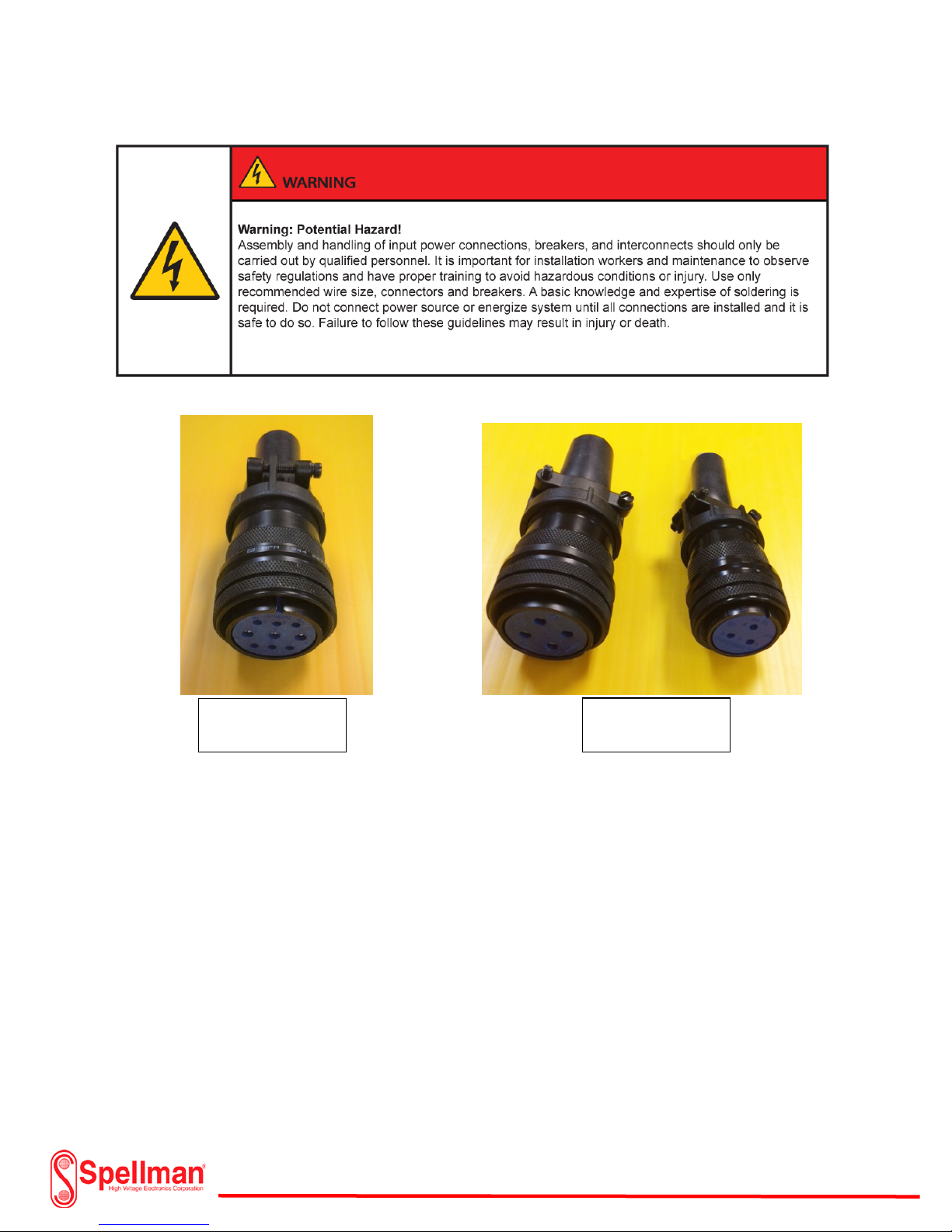
Power Connections (Unipolar Basic):
MS-3106A-24-11S
Connector & Clamp
Amphenol style connectors are included with the XRV Generator for connecting power to the unit.
There are two types of connectors. Up to 4 kilowatt generators use an Amphenol MS3106A-24-11S
straight connector for connecting input power. The 6 kilowatt generator requires a 3 phase input and
uses two separate connectors. One connector is for the Mains Input and the remaining is for the
Auxiliary Input.
118157-001 Rev C
Page 60 of 98
Page 61

Power Connections (Unipolar Basic):
6kW Input Power Connectors
Use stranded copper wire #8 AWG for the Input power Mains and Ground connection. Use stranded
copper wire #12 AWG for the Auxiliary Line, Neutral and Ground connection. Input power requirements
for the 4kW Generators are 180Vac to 264Vac ± 10%, 30A maximum for Mains and 5A maximum for
Auxiliary.
The 6 kilowatt generator uses an MS3106A-24-22S style connector for the Mains Input and an
MS3106-20-3S style connector for the Auxiliary Power Input. The 6kW generators require 3 Phase
208Vac ±10%, 30A maximum input or 400Vac ±10%, 15A Max. Input. The input power is selected when
placing the order for the XRV Generator . The Auxiliary Power Input requires a separate 230 Vac ±10%,
5A maximum source. Use #10 AWG copper stranded wire for each phase and ground on the Input Power
Mains JB-1. Use #12 AWG copper stranded wire for each line and ground on the Input Power Auxiliary
JB-2.
Page 61 of 98
118157-001 Rev C
Page 62
Power Connections (Unipolar Basic):
4kW Input Power
Connector
6kW Input Power
Connectors
The input power connectors are required to have soldered connections. Avoid shorts or loose wiring
when assembling. Use an ohmmeter to check for shorted connections. Use the appropriate size wire for
each connection. Input power wires should be run neat and as short as possible. Avoid high traffic areas
or places where they are easily damaged by other equipment. When assembling, remove the clamp and
shell to expose the pin cups. Remove the insulation from one end of the wire (approximately 3/8”) so
the bare wire will touch the bottom of the solder cup and be level with the top. Use the appropriate
wire size according to the connector specification. Slide a 1-1/4 inch piece of shrink tubing over the wire
insulation for the final step. Using a soldering iron, tin the stranded wire from the tip up to the
insulation. Place the wire straight into the pin cup so that the tip rests on the bottom and apply the
soldering iron to the outside of the cup. Insert the solder into the cup and apply until it almost fills to the
top. Let the connection and wire cool. Check for cold solder joints or solder bridges. Slide the shrink
tubing down over the cup pin and heat the tubing with a heat gun so that it fits snugly over the wire and
cup. Repeat the procedure for the remaining connections. Check each connection so that it is secure and
not touching any other connections. Slide down the cover and ring clamp with the rubber shroud
toward the connector and tighten. Secure the wire clamp by tightening the two screws.
118157-001 Rev C
Page 62 of 98
Page 63

Strip and Tin
Insert Wire into Pin Cup
and Apply Solder
Slide Shrink Tubing Over
Solder Cup and Apply Heat
Shrink Tubing Over
Completed XRV Cable, Clamp
Power Connections (Unipolar Basic):
Appropriate Size Wire
Soldered Connections
and Rubber Shroud
The input power connections for the 6 kilowatt XRV Generator is the same procedure as above with the
exception of the additional connector and different wire size. Check all power connections to the XRV
Generator before any connections to the mains and auxiliary power source.
Note: The cooler / chiller system will have instructions on cable sizing for power connections and
interlock connections.
118157-001 Rev C
Page 63 of 98
Page 64

Power Connections (Unipolar Basic):
Power Source Connections (Unipolar Basic):
A single phase 208 Vac, 60 Ampere power source is required for the 4 kilowatt XRV Generator. Use a
circuit breaker rated for 30 amperes for protection on the mains input and a circuit breaker rated for 10
amperes on the auxiliary input. Typically a 7.5 amp. breaker is used for the cooler and a 20 amp. breaker
for a chiller. Consult the cooler or chiller manual for circcuit breaker sizing. Consult Spellman High
Voltage for input voltage options.
118157-001 Rev C
Page 64 of 98
Page 65

Emergency Stop
Switch
Typical 208 Vac 3Ø
Power Source Connections (Unipolar Basic):
The circuit breakers should be located on a panel in an accessible area. It is recommended but not
necessary to have an emergency stop switch that will interrupt all the input power sources to the
generator and subsystem.
Verify that the ground buss bar in the main breaker panel connects to earth ground. Connect the mains
and auxiliary cable from the XRV generator and the cooler or chiller to the load side of the circuit
breakers.
Breaker Box
118157-001 Rev C
Page 65 of 98
Page 66

118157-001 Rev C
Page 66 of 98
Page 67

Power Source Connections (Unipolar Basic):
118157-001 Rev C
Page 67 of 98
Page 68

Power Source Connections (Unipolar Basic):
118157-001 Rev C
Page 68 of 98
Page 69

JB1 to JB2 Anode to
J2 to J6 Anode to Cathode
J3 to J7 Anode to Cathode
Anode Power & Feedback Connections
Power & Feedback Connections (Bipolar Basic):
The power connections for bipolar XRV Generators are identically the same as the unipolar XRV
Generators with the exception of an added chassis and three interconnect cables. Follow the procedure
for the unipolar generators but include the following cables and additional chassis ground. See page 35
for system diagram.
Cathode Power Cable
Feedback Cable
Inverter Control Cable
118157-001 Rev C
Page 69 of 98
Page 70

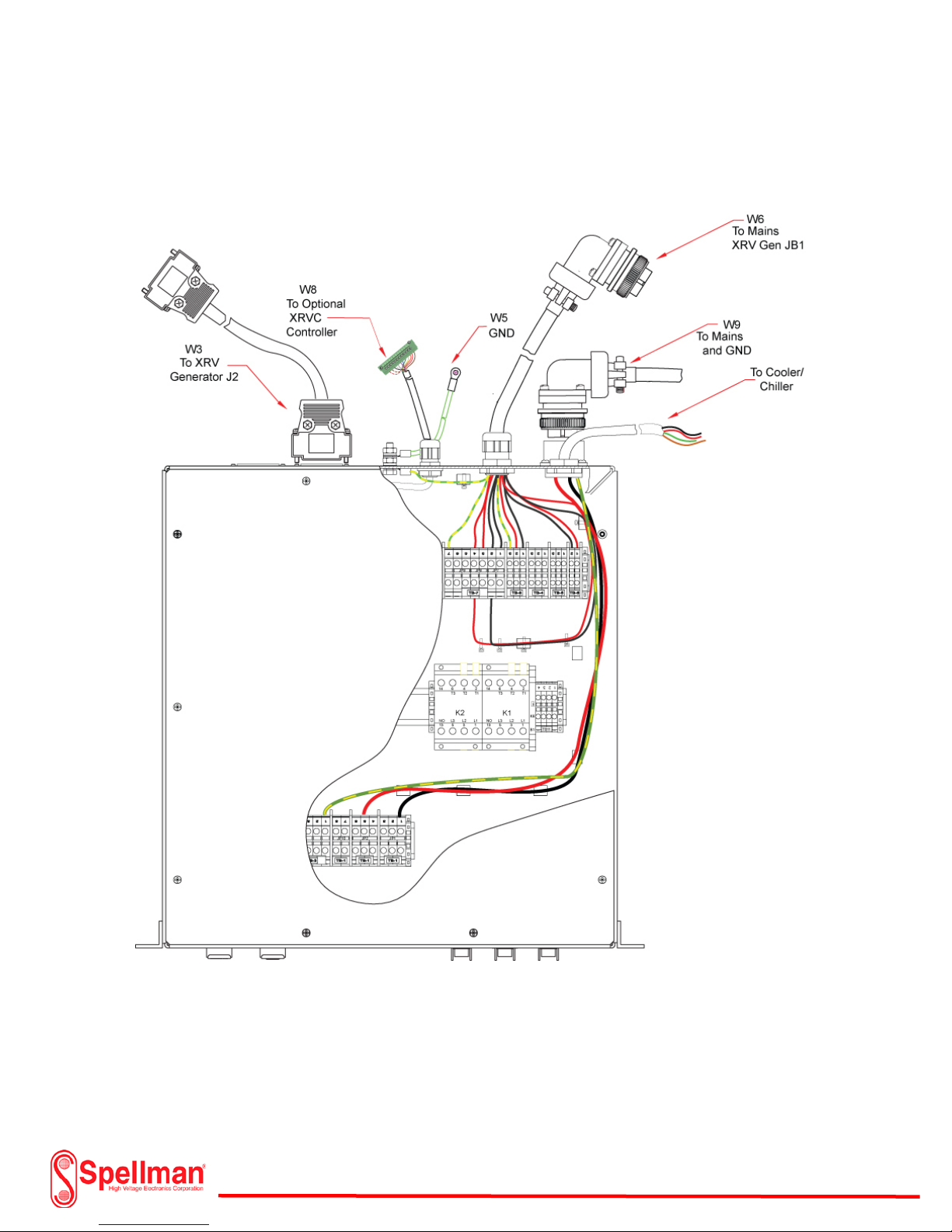
Power Connections (I/O System Interface Box):
I/O Box Configuration without
I/O Box Configuration with
The I/O Box offers a convenient method to connect the input power, the XRVC Controller, XRV
Generator and Cooler/Chiller and associated interlock circuits. If the I/O System Interface Box is used
without the XRVC Controller, it will include a key switch and 3 status indicators on the left side of the
front panel. If the XRVC Controller is used, then the left side of the panel will be blank.
Optional XRVC Controller
Both I/O Boxes include an Amphenol style connector on the rear panel for input power connections. The
circular connector can be either supplied as a separate piece or with the user specified cable length. If
the user decides to install the cable, use #8 AWG copper stranded wire soldered to the Amphenol
mating connector.
118157-001 Rev C
Optional XRVC Controller
Page 70 of 98
Page 71

Power Connections (I/O System Interface Box):
Note: Included cables with the I/O Box not shown for the
Generator Power, or XRVC Controller
Connect the ground lug on the rear panel to earth ground. Use a minimum of #10 AWG copper stranded
wire. Remove the top cover of the I/O Box for the Chiller or Cooler Interlock and power cable
installation. The Chiller or Cooler includes instructions for sizing the input power wire and detailing
water or oil flow and thermal interlock connections. Remove the top of the I/O Box and locate TB-4 and
TB-5. Route the input power wires from the Cooler or Chiller through the “Cooler” wire grommet and
connect to TB-4 Terminals 1, 2 and 3. Make sure that #3 is the ground connection from the Cooler or
Chiller. The Cooler or Chiller voltage is normally 230Vac single phase. Consult the manufacturer for
additional information. Connect the interlock switches for temperature and coolant flow from the
Cooler or Chiller through the “Cooler “grommet to TB-5, Terminals 1 and 3. Refer to cutout of I/O Box
diagram for connection locations.
Interlock Switches Cooler/Chiller
118157-001 Rev C
Page 71 of 98
Page 72

Power Connections (I/O System Interface Box):
118157-001 Rev C
Page 72 of 98
Page 73

Power Connections (I/O System Interface Box):
The I/O Box also includes an additional door interlock that may be used to interrupt power to the XRV
Generator in the event of unauthorized access to the X-ray chamber or other restricted areas. The
interlock connection is located on TB6 terminals 1 and 2. Use #16 AWG copper wire for the connections.
118157-001 Rev C
Page 73 of 98
Page 74

Power Connections (I/O System Interface Box):
C.D.R.H. Bridge Jumper Location TB-7
If a Door Power Interlock is used, remove the bridge jumper on TB7 terminals 1 and 2 and terminals 3
and 4. The Power Interlock is designed for use with C.D.R.H. requirements that are mounted to an x-ray
cabinet and door to provide the required disconnection of the input voltage independent of any moving
parts other than the door.
118157-001 Rev C
Page 74 of 98
Page 75

Main Input Power Connections (I/O System Interface Box):
The main input power connections will depend on the power rating of the XRV Generator. A 4kW XRV
Generator will require a single phase 180Vac to 264Vac source while the 6kW XRV Generator requires a
3 phase 208Vac +/-10% Input. The input voltage requirement for the 6kW units must be specified by the
user when purchased. If the user installs the input power cables, the appropriate wire size must be used.
Recommended wire for the 4kW generators and below is copper stranded #8 AWG. The wire size for the
6kW 3 phase systems is #10AWG due to the higher current draw on the input line. With the exception of
the Cooler/Chiller and Power Door Interlock connections, all of the cabling and connectors are provided
with the I/O System Interface Box to easily connect all of the subsystem components.
Note: Although a 3 phase 400Vac system can be selected, the I/O Subsystem Box for that voltage is
not available at this time.
118157-001 Rev C
Page 75 of 98
Page 76

Main Input Power Connections (I/O System Interface Box):
118157-001 Rev C
Page 76 of 98
Page 77

I/O Subsystem Interface Box (System Diagram):
118157-001 Rev C
Page 77 of 98
Page 78

XRVC Control Box:
The XRVC Control Box eliminates the need of having a personal PC to run and monitor the XRV
Generator and subsystem components. It employs an embedded computing system that runs a custom
graphical use (GUI) interface and allows the user to configure custom X-ray tube profiles for any of the
Spellman XRV series. Although it can be used without the I/O System Interface Box, it is more readily
integrated with it. The I/O Box includes the cables and connectors that intuitively connects to the XRVC
Controller. The placement and setup is relatively quick and allows the user a plug and play system.
Instructions on setting up the XRVC controller and operation are covered in the XRVC manual.
118157-001 Rev C
Page 78 of 98
Page 79

XRVC Controller, I/O System Interface Box, Cooler/Chiller,
XRVC Control Box and I/O System Box Setup:
XRV Generator and X-Ray Tube Setup for 4kW System
Page 79 of 98
118157-001 Rev C
Page 80

XRVC Controller, I/O System Interface Box, Cooler/Chiller,
XRVC Control Box and I/O System Box Setup:
118157-001 Rev C
XRV Generator and X-Ray Tube Setup for 6kW System
Page 80 of 98
Page 81

GUI Installation:
The GUI is designed to control the XRV series x ray generator. It allows users to control all necessary
functions of the x-ray generator from a user-friendly windows base menu. Functionality is organized into
nine screens that appear as tabs within the GUI. The “Main Control” screen will generally be the used
most frequently. Additional screens for seasoning, communication, user configuration and filament
control provide functionality necessary to control and monitor all aspects of the XRV series power
supplies.
1.1 System Requirements
• A computer with a male RS232 D 9 pin connector
• Windows XP, Windows 7, or Windows 10
• CD-ROM drive, USB or from Spellman website
• Color Monitor with display resolution of 1024 X 768
2.2 Installation via CD
1. Insert the XRV disk in the CD Drive
2. Click “Start” Button on screen
3. Click on “My Computer icon”
4. Click CD drive icon
5. Double-click on the XRV setup icon
6. Follow the instructions displayed on screen
2.3 Installation via USB Flash Drive
1. Insert the XRV flash drive in the USB port of the computer
2. Open the GUI 1.8kW to 6kW folder
3. Open the GUI X4867 folder
4. Open the GUI X4867 subfolder
5. Open D0204001_V15038 folder
6. Double Click Setup 1 Icon
7. Follow instructions displayed on screen
118157-001 Rev C
Page 81 of 98
Page 82

Flash Drive USB installation Step 1
Flash Drive USB installation Step 2
118157-001 Rev C
Page 82 of 98
Page 83

Flash Drive USB installation Step 3
Flash Drive USB installation Step 4
118157-001 Rev C
Page 83 of 98
Page 84

Flash Drive USB installation Step 5
XRV Generator Rear Panel
Software Communication:
After the GUI is installed, shut down the computer. Select which type of communication cable will be
used to control the XRV Generator. Connect a 9 pin com port (RS-232), Ethernet or USB from the
computer to the XRV Generator J3, J4 or J5 input connector. Make sure that the appropriate interface
cable is plugged in before power is applied to the computer or XRV Generator.
118157-001 Rev C
Page 84 of 98
Page 85

Software Communication:
When the appropriate cable is connected, power up the computer and ONLY the auxiliary power on the
XRV Generator. Do NOT apply power to the Mains on the generator. Launch the GUI from the computer
and click on the “Coms” Tab. Select the desired communication setup as illustrated in the diagram.
Note: When using the XRVC control subsystem option, no software installation is necessary.
Note: When using the RS232 method of communication, the user must select a Com
port, Baud Rate, Data Bits, Parity, and Stop Bits. When using the Ethernet method of
communication, the user must select a port number and IP address. Be sure to press
the “Click here to save these settings” button when finished.
118157-001 Rev C
Page 85 of 98
Page 86

Software Communication:
Once communication has been set up, click on the “Main Control” tab to verify the data transmission
information is transferred from the XRV Generator to the computer as shown above. For additional
information regarding software installation and control, refer to Spellman High Voltage “XRV Controller
Reference Guide Manual (Classic)”.
118157-001 Rev C
Page 86 of 98
Page 87

X-Ray Tube Filament Calibration:
The X-ray tube filament current is required to be calibrated once the initial installation is completed
or if the X-ray tube was replaced. The calibration is required for both the large and small filaments. If
the tube only has one filament, only the large filament will require calibration. The tube
manufacturer will recommend the maximum setting for each filament. In most cases, the filament
current supplied will be DC unless the user has specified an AC filament source when procuring the
XRV Generator. If an AC filament source was selected, then an appropriate meter having an
adequate frequency response of 25kHz or more should be used to measure the RMS current.
Current measurements are made directly in the high voltage cable that is connected to the X-ray
tube. Refer to the current limit data for small and large found in the Tube Specification Data Sheet.
The filament measuring and calibration adapter is available as an accessory kit from Spellman High
Voltage.
118157-001 Rev C
Page 87 of 98
Page 88

X-Ray Tube Filament Calibration:
Test equipment required:
1=Measuring Adapter for high voltage socket
2= Measuring Adapter for high voltage cable plug
3= Digital Multimeter (Customer Supplied)
C=Com m on Connection, L= Large Filament Connection, S= Small Filament Connection
118157-001 Rev C
Page 88 of 98
Page 89

X-Ray Tube Filament Calibration Setup:
118157-001 Rev C
Page 89 of 98
Page 90

X-Ray Tube Filament Calibration Using GUI:
1) Connect the filament calibration for the large or small filament as shown in the diagram. Make
sure the common is connected to earth ground.
2) Energize the Auxiliary circuit breaker to the XRV Generator.
Do Not Energize the Main Circuit Breaker!
3) Launch the supplied XRV software and verify the XRV Generator is communicating with the GUI.
4) Refer to the manufacturer’s X-ray tube specification and verify the maximum current for the
filament.
118157-001 Rev C
Page 90 of 98
Page 91

5) Click on the “User Config” tab and enter “useraccess” for the password.
6) Enter the “Large Filament Limit” current and Click to send.
Note: In this example, the tube only has a large filament. The “Small Filament Limit”
setting can be ignored.
118157-001 Rev C
Page 91 of 98
Page 92

7) Click on the “Fil/Local Cntrl” tab and select “Large” Filament.
8) Select Filament “On”
118157-001 Rev C
Page 92 of 98
Page 93

9) Return to “UserConfigs” tab and enter password.
10) Starting from 0 current, slowly increase the Large Filament current Pre-heat setting while
monitoring the digital multimeter. Increase the current until the multimeter reads 10% below
the maximum current setting on the tube. Do not exceed the maximum tube current!
118157-001 Rev C
Page 93 of 98
Page 94

11) The actual filament current and the monitored current monitored by the GUI should be within
1% tolerance. If the reading is not at spec, adjust R53 (LARGE FIL I CAL) on Filament/Feedback
board XRV (Part # 460158-XXX).
12) Select the “Fil/Local Cntrl” tab and select Filament Control “Off”. The Small Filament Calibration
follows the same procedure as the Large Filament Calibration. Ensure the multi-meter current
connections are through the small filament as referred to in the diagram. For additional
information, see Filament Calibration Procedure in the XRV Generator Manual.
118157-001 Rev C
Page 94 of 98
Page 95

13) Return to “User Configs” and enter password.
14) Return “Preheat Settings” to original filament current settings or recommended manufacturer
recommended settings. Click to save and set the preheat limit.
118157-001 Rev C
Page 95 of 98
Page 96

Accessory Test Kits for XRV Generators:
XRV-14-1 (R24 Dummy/Blanking Plug)
R24 test plug useful for evaluating or troubleshooting
XRV160 model generators or X-ray tube functionality. The
plug is inserted into the high voltage receptical and allows
for operation of the XRV Generator without the X-ray tube
load.
XRV-14-2 (R28 Dummy/Blanking Plug)
R28 test plug useful for evaluating or troubleshooting
XRV225 model generators or X-ray tube functionality. The
plug is inserted into the high voltage receptical and allows
for operation of the XRV Generator without the X-ray tube
load.
XRV-14-3 (Filament Adapter with Resistor)
XRV filament power supply calibration tool utilizing a
resistive load for filament current calibration and
verification. For use with both the XRV160 and XRV225
models. Customer supplied voltmeter is required.
118157-001 Rev C
Page 96 of 98
Page 97

XRV-1-(x)
High Voltage Power Supply (A1)
XRV-2-(x)
X-Ray Tube (A2)
XRV-3-(x)
HV Cable & GND Cable Kit (W1 & W2)
XRV-4-(x)
HV Cable Flange (Power Supply Side) (FL1)
XRV-5-(x)
HV Cable Flange (X-ray Tube Side) (FL2)
XRV-6-(x)
Cooler/Chiller (A3)
XRV-7-(x)
Cooling Hose (Item 3 & 4)
XRV-8-(x)
Controllers & Cable Kit (A4, W3, W4, W5)
XRV-9-(x)
I/O Box (A5)
XRV-10-(x)
Mains/Aux & GND Cable Kit (W6 & W10)
XRV-11-(x)
I/O Box to Door Interlock Cable (W7)
XRV-12-(x)
I/O Box to Controller Cable (W8)
XRV-13-(x)
I/O Box Input Power Cable (W9)
XRV-14-(x)
Test Kits for XRV
Accessory Test Kits for XRV Generators:
XRV-14-4 (Filament Measuring Adapter)
XRV X-ray tube filament calibration tool utilizing a unique
adpater between the high voltage cable plug and the XRV
Generator for X-ray tube filament current calibration and
verification. For use with both the XRV160 and XRV225
models. Customer supplied ampere meter is required.
XRV Sub-system Nomenclature:
For a detailed list, refer to Spellman Drawing # 408216-001
118157-001 Rev C
Page 97 of 98
Page 98

DESCRIPTION
XRV160
XRV 225
XRV320
XRV450
System Diagram
441202-001
441204-001
441177-001
441178-001
Overall Drawing
407175-001
407181-001
407035-001
407034-001
Assembly Drawing Cathode
407106-001
407118-001
407106-001
407118-001
Fil/FDBK Bd. Assy. Cathode
460158-001
460158-001
460158-001
460158-001
Fil/FDBK Bd. Schematic
441170-001
441170-001
441170-001
441170-001
Inverter Module Assembly
407105-001
407000-001
407105-001
407000-001
Power Inverter Bd. Assy.
460156-002
460156-001
460156-002
460156-001
Power Inverter Bd. Sch.
441164-001
441164-001
441164-001
441164-001
System Control Assy.
460130-001
460130-001
460130-001
460130-001
System Control Bd. Sch.
441105-001
441105-001
441105-001
441105-001
Front Panel LED Display
460124-001
460124-001
460124-001
460124-001
Front Panel LED Display
340352-001
340352-001
340352-001
340352-001
XRV
DESCRIPTION
DRAWING NUMBER
XRV UNIPOLAR/BIPOLAR SYSTEM DIAGRAM SCH.
408216-001
XRV-9-1
I/O BOX,RACK MOUNT,W/O CONTROLLER SCH.
441458-001
XRV-9-2
I/O BOX,RACK MOUNT,WITH CONTROLLER SCH.
441458-002
XRV-9-5
I/O BOX,RACK MOUNT,W/O CNTL, W/SAFETY RELAY SCH.
441458-003
XRV-9-6
I/O BOX,RACK MOUNT,W/CNTL, W/SAFETY RELAY SCH.
441458-004
XRV-9-7
I/O BOX, RACK MOUNT THREE PHASE, W/O CONTROLLER SCH.
441458-001
XRV-9-8
I/O BOX, RACK MOUNT THREE PHASE, WITH CONTROLLER
441458-002
XRV-8-1
CONTROLLER, RACK MOUNT WITH CABLE KIT
441484-001
XRV-8-2
CONTROLLER, BENCH MOUNT WITH CABLE KIT
441484-001
Drawing List:
XRV Generator
Assembly Drawing Anode
Fil/FDBK Bd. Assy. Anode
Assembly
Schematic
Sub-system
-
-
-
-
407110-001
460158-002
407098-001
460158-002
118157-001 Rev C
Page 98 of 98
 Loading...