

Page 1

Instruction Manual
SPELLMAN
HIGH VOLTAGE ELECTRONICS
CORPORATION
One Commerce Park
Valhalla, New York, 10595
+1(914) 686-3600* FAX: +1(914) 686-5424*
E-mail: sales@spellmanhv.com
Website: www.spellmanhv.com
XRB011
R
XRB011 User’s Manual 118148-001 Rev A
Page 2
IMPORTANT SAFETY PRECAUTIONS
SAFETY
THIS POWER SUPPLY GENERATES VOLTAGES THAT ARE DANGEROUS AND MAY BE FATAL.
OBSERVE EXTREME CAUTION WHEN WORKING WITH THIS EQUIPMENT.
High voltage power supplies must always be grounded.
Do not touch connections unless the equipment is off and the
Capacitance of both the load and power supply is discharged.
Allow five minutes for discharge of internal capacitance of the power supply.
Do not ground yourself or work under wet or damp conditions.
SERVICING SAFETY
.
Maintenance may require removing the instrument cover with the power on.
Servicing should be done by qualified personnel aware of the electrical hazards.
WARNING note in the text call attention to hazards in operation of these units
that could lead to possible injury or death.
CAUTION notes in the text indicate procedures to be followed to avoid possible
damage to equipment.
Copyright 2000, Spellman High Voltage Electronics Corporation. All Rights Reserved.
This information contained in this publication is derived in part from proprietary and patent data. This information has
been prepared for the express purpose of assisting operating and maintenance personnel in the efficient use of the
model described herein, and publication of this information does not convey any right to reproduce it or to use it for
any purpose other than in connection with installation, operation, and maintenance of the equipment described.
118091-001 REV. B
Page 3
WICHTIGE SICHERHEITSHINWEISE
SICHERHEIT
DIESES HOCHSPANNUNGSNETZTEIL ERZEUGT LEBENSGEFÄHRLICHE HOCHSPANNUNG.
SEIN SIE SEHR VORSICHTIG BEI DER ARBEIT MIT DIESEM GERÄT.
Das Hochspannungsnetzteil muß immer geerdet sein.
Berühren Sie die Stecker des Netzteiles nur, wenn das Gerät ausgeschaltet ist und die elektrischen
Kapazitäten des Netzteiles und der angeschlossenen Last entladen sind.
Die internen Kapazitäten des Hochspannungsnetzteiles benötigen ca. 5 Minuten, um sich zu entladen.
Erden Sie sich nicht, und arbeiten Sie nicht in feuchter oder nasser Umgebung.
SERVICESICHERHEIT
Notwendige Reparaturen können es erforderlich machen, den Gehäusedeckel während des Betriebes zu
entfernen.
Reparaturen dürfen nur von qualifiziertem, eingewiesenem Personal ausgeführt werden.
“WARNING” im folgenden Text weist auf gefährliche Operationen hin, die zu Verletzungen oder zum Tod
führen können.
“CAUTION” im folgenden Text weist auf Prozeduren hin, die genauestens befolgt werden müssen, um
eventuelle Beschädigungen des Gerätes zu vermeiden.
118091-001 REV. B
Page 4
PRECAUTIONS IMPORTANTES POUR VOTRE SECURITE
CONSIGNES DE SÉCURITÉ
CETTE ALIMENTATION GÉNÈRE DES TENSIONS QUI SONT DANGEUREUSES ET PEUVENT ÊTRE FATALES.
OYEZ EXTRÊMENT VIGILANTS LORSQUE VOUS UTILISEZ CET ÉQUIPEMENT.
S
Les alimentations haute tension doivent toujours être mises à la masse.
Ne touchez pas les connectiques sans que l’équipement soit éteint et que la capacité à la fois de la charge et de
l’alimentation soient déchargées.
Prévoyez 5 minutes pour la décharge de la capacité interne de l’alimentation.
Ne vous mettez pas à la masse, ou ne travaillez pas sous conditions mouillées ou humides.
CONSIGNES DE SÉCURITÉ EN CAS DE REPARATION
La maintenance peut nécessiter l’enlèvement du couvercle lorsque l’alimentation est encore allumée.
Les réparations doivent être effectuées par une personne qualifiée et connaissant les risques électriques.
Dans le manuel, les notes marquées « WARNING » attire l’attention sur les risques lors de la manipulation de ces
équipements, qui peuvent entrainer de possibles blessures voire la mort.
Dans le manuel, les notes marquées « CAUTION » indiquent les procédures qui doivent être suivies afin d’éviter
d’éventuels dommages sur l’équipement.
118091-001 REV. B
Page 5
IMPORTANTI PRECAUZIONI DI SICUREZZA
SICUREZZA
QUESTO ALIMENTATORE GENERA TENSIONI CHE SONO PERICOLOSE E
POTREBBERO ESSERE MORTALI.
PONI ESTREMA CAUTELA QUANDO OPERI CON QUESO APPARECCHIO.
Gli alimentatori ad alta tensione devono sempre essere collegati ad un impianto di terra.
Non toccare le connessioni a meno che l’apparecchio sia stato spento e la capacità interna
del carico e dell’alimentatore stesso siano scariche.
Attendere cinque minuti per permettere la scarica della capacità interna dell’alimentatore
ad alta tensione.
Non mettere a terra il proprio corpo oppure operare in ambienti bagnati o saturi d’umidità.
SICUREZZA NELLA MANUTENZIONE.
Manutenzione potrebbe essere richiesta, rimuovendo la copertura con apparecchio
acceso.
La manutenzione deve essere svolta da personale qualificato, coscio dei rischi elettrici.
Attenzione alle AVVERTENZE contenute nel manuale, che richiamano all’attenzione ai
rischi quando si opera con tali unità e che potrebbero causare possibili ferite o morte.
Le note di CAUTELA contenute nel manuale, indicano le procedure da seguire per evitare
possibili danni all’apparecchio.
118091-001 REV. B
Page 6

SPELLMAN HIGH VOLTAGE Introduction 1
Installation and Operating Manual Page1-1 118149-001 REV F
XRB011 INTRODUCTION
1
XRB011
SERVICE
AND
INSTALLATION
MANUAL
INSTALLATION
2
INTERFACING
3
TROUBLESHOOTING
4
SCHEMATICS (Simplified Diagram)
5
Page 7

SPELLMAN HIGH VOLTAGE Introduction 1
Installation and Operating Manual Page1-2 118149-001 REV F
CHAPTER 1
XRB011 INTRODUCTION
CONTENTS:
Section
1.1 XRB011 DESCRIPTION ............................................................................................................................................... 3
1.2 TECHNICAL SPECIFICATIONS ........................................................................................................................................... 3
1.2.1 Generator Hardware Specifications .......................................................................................................................... 3
1.2.2 Generator Control Modes / Application Features ..................................................................................................... 3
1.2.3 Power Supply Requirements ...................................................................................................................................... 3
1.2.4 Environment Requirements ........................................................................................................................................ 4
1.2.5 Mechanical ................................................................................................................................................................. 5
1.3 THEORY OF OPERATION .......................................................................................................................................... 7
1.3.1 Function Overview ................................ ................................................................................................ ..................... 7
1.3.2 Input Line Power ........................................................................................................................................................ 7
1.3.3 HV Inverter ................................................................................................................................................................ 7
1.3.4 High Voltage Transformer ......................................................................................................................................... 7
1.3.5 High Voltage Assembly .............................................................................................................................................. 7
1.3.6 System Control PWB .................................................................................................................................................. 7
1.3.7 Filament Power .......................................................................................................................................................... 8
1.3.8 High Voltage Interlock ............................................................................................................................................... 8
1.4 SAFETY ......................................................................................................................................................................... 9
1.4.1 Safety and Warning Symbols ...................................................................................................................................... 9
Page 8

SPELLMAN HIGH VOLTAGE Introduction 1
Installation and Operating Manual Page1-3 118149-001 REV F
1.1 XRB011 DESCRIPTION
The XRB011 MONOBLOCK is a complete integrated system consisting of a high voltage power supply
(HVPS), filament supply, X-ray tube and oil encapsulant which provide the required high voltage insulation in
one compact enclosure. The combination of proprietary control system and protection circuitry enables the
supplies to operate under arcing and extreme transient conditions without damage or interruptions. Additional
advantages are the elimination of high voltage cables and extremely low leakage X-ray radiation.
The XRB011 incorporates local and remote programming, monitoring, and fault indicators including safety
interlock. The X-ray source is a sealed unit containing a HVPS and an X-ray tube. The insulating oil provides
electrical insulation for the high voltage sections of the power supply and the X-ray tube in a sealed tank. The
oil also functions as a coolant to carry heat away from the tube. Convection cooling augmented by customer
provided minimum 50cfm external fan is required for the 50W option. A rubber bellows in the tank of the X-ray
source compensates for the expansion of the oil as the oil temperature varies with operating conditions thereby
eliminating the need for bulky overflow tank.
.
1.2 TECHNICAL SPECIFICATIONS
1.2.1 Generator Hardware Specifications
kVp range:
35 to 80 kVp output capability
kVp steps:
Continuous with 12 bits resolution
kVp accuracy:
<=1% (measured after kVp rises to the
peak level)
Ripple (kV):
<= 1% Peak to Peak
Settling time:
< 10ms to within 95% of the
programmed voltage
Reproducibility:
<0.5%
Stability:
<=0.01% per 8 hours after a ½ hour
warm up
Temperature Coefficient:
<=100ppm/ ℃
Time range:
XRB011 is specified as a Continuous
operation.
mA :
250µA maximum for 20W option
700µA maximum for 50W option
mA accuracy:
<2.5% (measured after mA rises to
stable DC level)
mA range
0 to 250 µA for 20W option
0 to 700 µA for 50W option
Reproducibility:
<0.5%
1.2.2 Generator Control Modes / Application Features
Manual Operating Mode – 2 Parameters Mode (kV, mA)
System Communication Protocol / Fault & Error Management
See details in the Serial Communication Protocol Specifications
1.2.3 Power Supply Requirements
Single Phase
Page 9

SPELLMAN HIGH VOLTAGE Introduction 1
Installation and Operating Manual Page1-4 118149-001 REV F
Line Voltage
24VDC±1VDC, 2.5A (20W option). 4A (50W option)
The following table defines the power line requirements for the generators.
NOTE: THE FOLLOWING TABLE CONTAINS RECOMMENDED VALUES FOR THE 24V INPUT POWER.
A POOR QUALITY INPUT LINE MAY RESULT IN THE INSTALLER HAVING TO
DERATE THE GENERATOR'S MAXIMUM POWER
Mains
Voltage
Minimum
Recommended
Minimum
Recommended
Ground Wire Size
Apparent
Mains
Resistance
24VDC
J1-1
J1-2
J1-3
#20 AWG (0.52 mm
2
)
#20 AWG (0.52 mm
2
)
#20 AWG (0.52 mm
2
)
0.033
0.033
0.033
24V RETURN
J1-5
J1-6
J1-7
#20 AWG (0.52 mm2)
#20 AWG (0.52 mm2)
#20 AWG (0.52 mm2)
0.033
0.033
0.033
1.2.4 Environment Requirements
Operating Environment
Operating Temperature
0 to 40 C (32 to 104 F).
Relative Humidity
10 to 95%, non-condensing.
Atmospheric pressure range
500 to 1060 hPa (375 to 795 mm Hg).
TRANSPORT AND STORAGE
Ambient temperature range
-20 to 70 C (-4 to 158 F).
Relative humidity
5 to 95%, non-condensing.
Atmospheric pressure range
500 to 1060 hPa (375 to 795 mm Hg).
Page 10
SPELLMAN HIGH VOLTAGE Introduction 1
Installation and Operating Manual Page1-5 118149-001 REV F
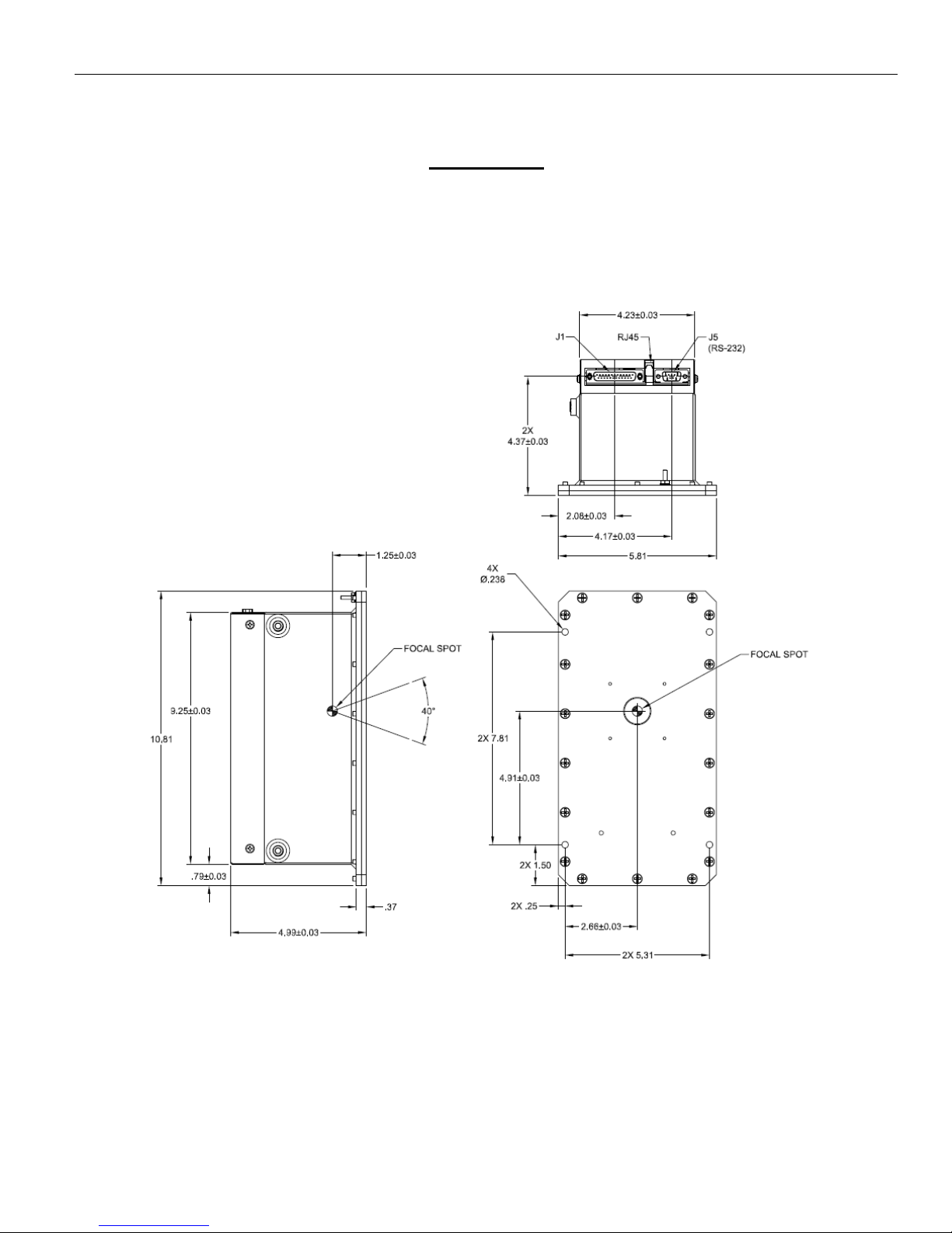
1.2.5 Mechanical
20W OPTION
Page 11
SPELLMAN HIGH VOLTAGE Introduction 1
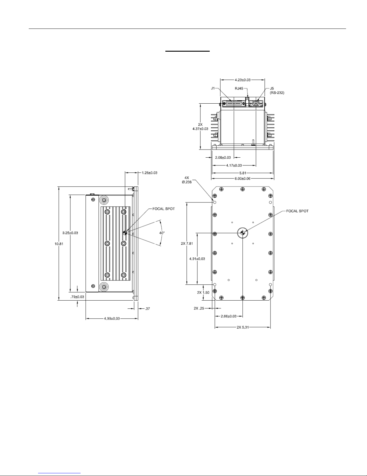
Installation and Operating Manual Page1-6 118149-001 REV F
50W OPTION
Page 12

SPELLMAN HIGH VOLTAGE Introduction 1
Installation and Operating Manual Page1-7 118149-001 REV F
1.3 THEORY OF OPERATION
1.3.1 Function Overview
The XRB011 MONOBLOCK Series is a complete integrated system consisting of a high voltage power
supply (HVPS), filament supply, X-ray tube and oil encapsulant which provide the required high voltage
insulation in one compact enclosure. The combination of proprietary control system and protection circuitry
enables the supplies to operate under arcing and extreme transient conditions without damage or interruptions.
Additional advantages are the elimination of high voltage cables and extremely low leakage X-ray radiation.
The XRB011 MONOBLOCK Series incorporates local and remote programming, monitoring, and fault
indicators including safety interlock. The X-ray source is a sealed unit containing a HVPS and an X-ray tube.
The insulating oil provides electrical insulation for the high voltage sections of the power supply and the X-ray
tube in a sealed tank. The oil also functions as a coolant to carry heat away from the tube. Convection cooling
augmented by customer provided minimum 50cfm external fan is required for the 50W option. A rubber
bellows in the tank of the X-ray source compensates for the expansion of the oil as the oil temperature varies
with operating conditions thereby eliminating the need for bulky overflow tank.
The XRB011 MONOBLOCK is basically a DC to DC power converter. Within the generator, conversions of DC
to DC, then to high frequency AC, then to high voltage DC take place. By reviewing further the subassemblies, a basic understanding of the process can be gained.
1.3.2 Input Line Power
The Input DC voltage provides the voltage for the high voltage inverter and the filament supply.
The line input voltage can vary from 23V up to 25V within the series.
1.3.3 HV Inverter
The inverter is a “Push-Pull” topology. Voltage mode control is used for driving the inverter. Two MOSFET
transistors are used as switches in the HV inverter. These MOSFET provide high frequency switching to
control the primary current flow in the high voltage transformer.
Circuits on the Control board provide the gate control of the switches. The PWM IC generates gate drive
control signals.
1.3.4 High Voltage Transformer
The output of the High Frequency Quasi-resonant Inverter is connected to the primary of the High Voltage
Transformer. The High Voltage Transformer is a step up type. Typical secondary voltage is in the range of
5.7kV depending upon output voltage ratings.
1.3.5 High Voltage Assembly
The High Voltage Assembly circuitry typically consists of two high voltage multipliers to generate ±40kV. The
high voltage section is a bipolar ground-referenced supply. The multiplier is a standard diode-capacitor
multiplier with seven stages of voltage multiplication and the divider is a precision resistance divider string.
Each supply is capable of generating 40 kV.
A high bandwidth resistive/capacitive divider provides voltage feedback for regulation and monitoring. A sense
resistor connected at the low voltage end of the High Voltage Rectifier provides current feedback for regulation
and monitoring.
1.3.6 System Control PWB
Control of the generator utilizes sophisticated analog and digital circuitry resulting in fast and accurate control,
protection and signaling to the user.
This generator is based on advanced PWM control utilizing the specific integrated circuit. Analog signals are
digitized in A/D converter and processed within DSP circuits to provide maximum accuracy and reliability.
All feedback signals are sent to the user interface through digital and D/A circuits where switching is possible
between feedback and program signals. This allows the user to preset the desired output before energizing
high voltage.
All program voltages are typically ramped up to set level by the digital ramp generator.
Page 13
SPELLMAN HIGH VOLTAGE Introduction 1
Installation and Operating Manual Page1-8 118149-001 REV F
A-D and D-A converters and drivers provide system Fault Control and Indication. User interface is processed
on this PWB as well, providing isolated relay coils, opt couplers and open collectors contact.
1.3.7 Filament Power
The filament inverter provides the filament power for the X-ray tube. The filament inverter is a high frequency,
series resonant inverter. The inverter provides ac current to the primary of the filament isolation transformer.
The filament isolation transformer secondary is connected to the filament tube. The filament power is
2.25Vac/1.7Aac.
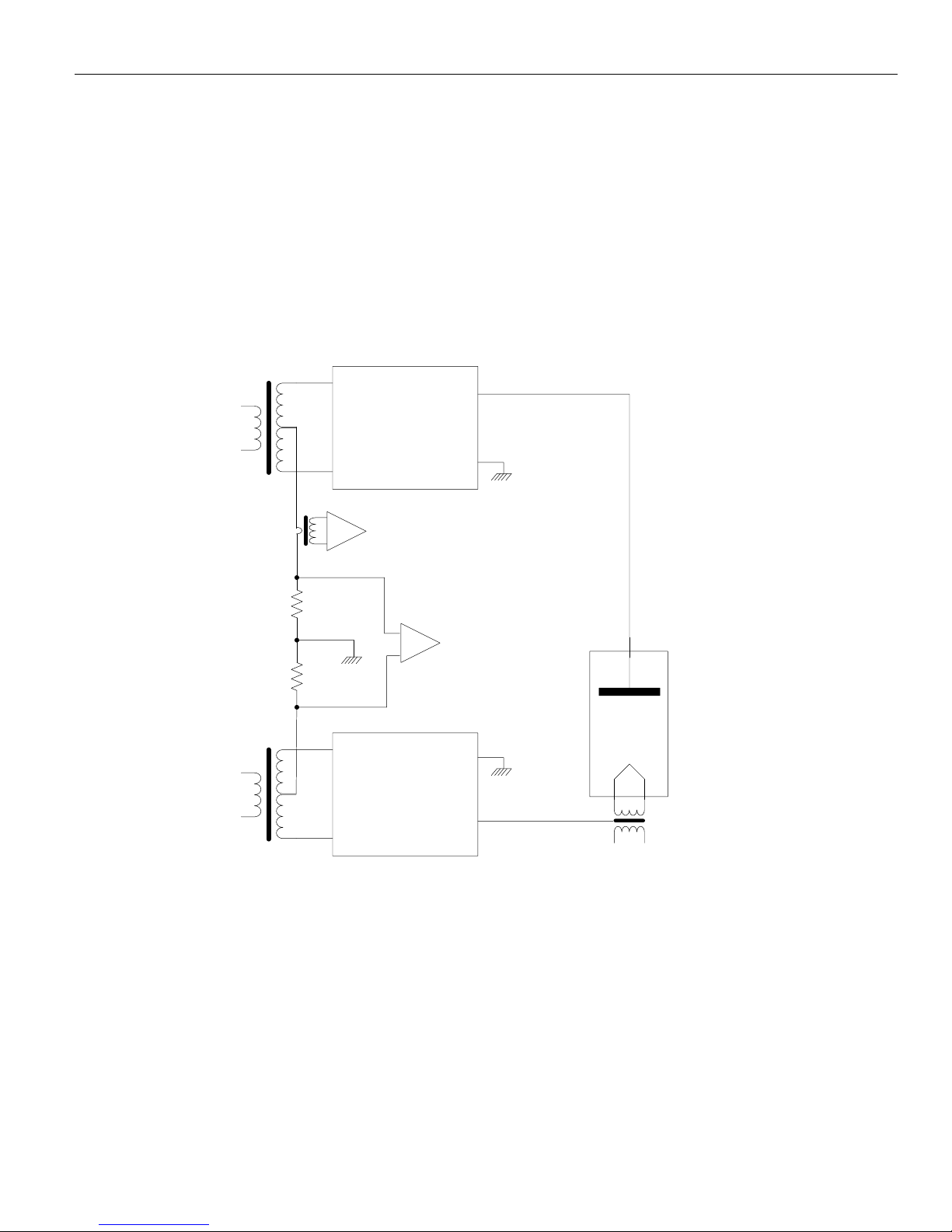
See Figure 1.2 for a simplified diagram of the X-RAY tube connection and current sensing circuits. The
filament circuitry also provides a variety of control, diagnostic and protection functions.
If any abnormal condition appears, monitoring circuitry will shut down the unit.
Figure 1.2 Simplified schematic of X-RAY tube connection
1.3.8 High Voltage Interlock
The XRB011 is equipped with safety interlocks for user personnel and equipment protection. An open interlock
circuit inhibits operation of the XRB011 MONOBLOCK.
POS HV MULT
NEG HV MULT
GND
+
-kV
+kV
FILAMENT
XFMR
X-RAY TUBE
ARC DETECT
mA Monitor
-
GND
GND
HV XFMR
HV XFMR
Page 14
SPELLMAN HIGH VOLTAGE Introduction 1
Installation and Operating Manual Page1-9 118149-001 REV F
1.4 SAFETY
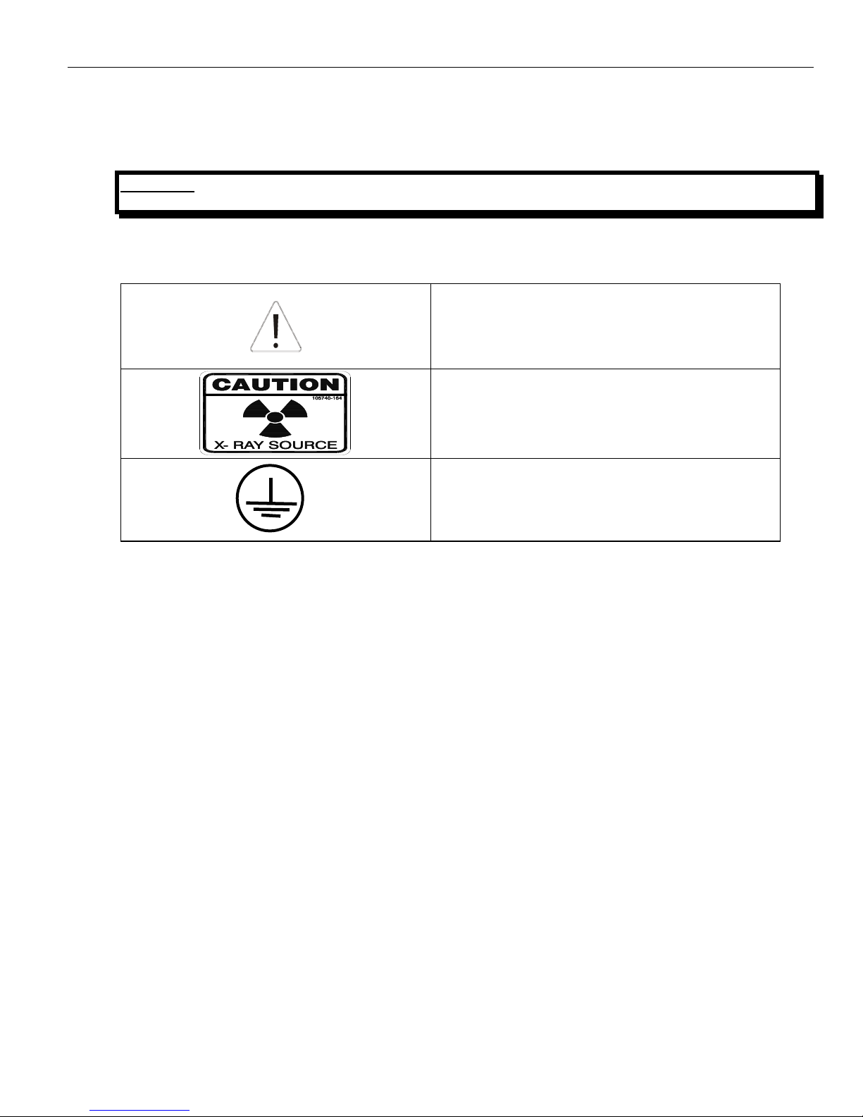
1.4.1 Safety and Warning Symbols
WARNING: THIS X-RAY UNIT MAY BE DANGEROUS TO OPERATOR UNLESS SAFE EXPOSURE
FACTORS AND OPERATING INSTRUCTIONS ARE OBSERVED.
The following advisory symbols are used on the safety warning labels, and/or on circuit boards.
“CAUTION” symbol used to indicate a potential
hazard to operators, service personnel or to the
equipment.
“CAUTION” symbol used to indicate an X-RAY
RADIATION EXPOSURE, is hazard to operators,
service personnel or to the equipment.
Protective Earth
IEC 60417-5017
Page 15

SPELLMAN HIGH VOLTAGE Installation 2
Installation and Operating Manual – XRB011 Page 2-10 118149-001 REV F
CHAPTER 2
INSTALLATION
CONTENTS:
2.1 INTRODUCTION ........................................................................................................................................................ 11
2.2 UNPACKING .............................................................................................................................................................. 11
2.3 OVERALL CONNECTIONS ................................................................................................................................ ................ 12
2.4 INPUT POWER VOLTAGE ........................................................................................................................................ 13
2.5 CABLE CONNECTION ILLUSTRATION .............................................................................................................................. 13
2.5.1 MULTI INTERFACE CABLE CONNECTIONS ....................................................................................................... 13
2.5.1 Pin Layout of the Multi interface ............................................................................................................................. 14
2.5.2 GROUND CONNECTION .......................................................................................................................................... 14
2.5.3 CHASSIS GROUND ......................................................................................................................................................... 15
2.5.4 X-RAY PORT ............................................................................................................................................................ 15
2.6 FINAL CHECKS .......................................................................................................................................................... 15
Page 16

SPELLMAN HIGH VOLTAGE Installation 2
Installation and Operating Manual – XRB011 Page 2-11 118149-001 REV F
2.1 INTRODUCTION
This Chapter contains instructions for unpacking the XRB011 MONOBLOCK, allowing for initial power-up
and exposures.
2.2 UNPACKING
WARNING: THE XRB011MONOBLOK WEIGHS APPROXIMATELY 20 POUNDS (9.07 KG) IN ITS
SHIPPING CONTAINER.
1. Inspect the package exterior for evidence of damage due to handling in transit. Notify the carrier
and Spellman immediately if damage is evident. Do not destroy or remove any of the packing
material used in a damaged shipment.
2. Remove the cardboard outer pack. See the cautionary note below before removing the pack.
CAUTION: OPEN THE CARDBOARD PACK CAREFULLY. SHARP TOOLS MAY DAMAGE THE
CONTENTS.
3. Set aside the cardboard pack(s).
4. After unpacking, inspect the panel and chassis for visible damage.
5. Keep the shipping containers. In case of shipping damage, place the unit(s) back in its shipping
pack and notify the carrier and the Customer Support Department as shown on the inside cover
page of this manual.
6. Fill out and mail the Warranty Registration card accompanying the unit. Spellman XRB011
MONOBLOCK is covered by warranty.
Page 17
SPELLMAN HIGH VOLTAGE Installation 2
Installation and Operating Manual – XRB011 Page 2-12 118149-001 REV F
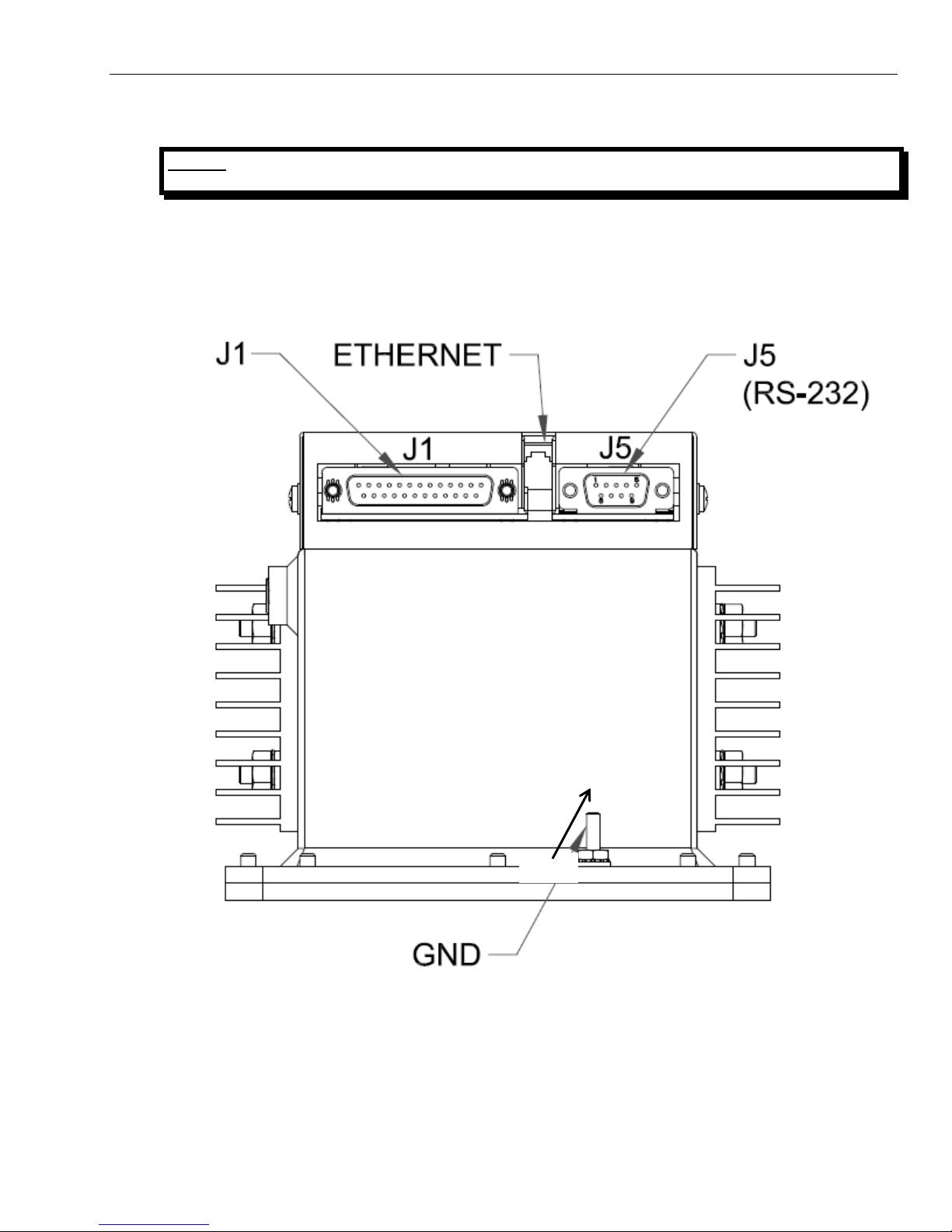
2.3 OVERALL CONNECTIONS
NOTE: THIS IS BASIC CONNECTION ILLUSTRATION FOR TESTING. MORE COMPLEX AND
DEDICATED CIRCUITRY IS NEEDED IN ULTIMATE APPLICATION.
All cables should be routed away from the X-Ray port, and dressed and secured neatly in place. Cables
should be cut to the correct length if possible as excess cabling may contribute to EMI/RFI problems. For
those cables that cannot be cut to the correct length, try to minimize the area inside any loops of excess
cable, as these loops are in effect an antenna.
Figure 2-1: XRB011 I/O location
GND
RJ45
Page 18
SPELLMAN HIGH VOLTAGE Installation 2
Installation and Operating Manual – XRB011 Page 2-13 118149-001 REV F
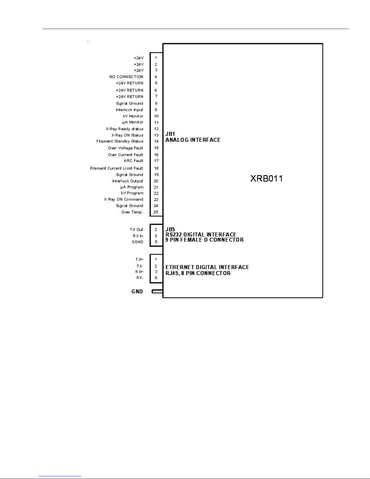
Figure 2-2: Overall connection
2.4 INPUT POWER VOLTAGE
1. Check the input voltage rating on the nameplate of the supply and make certain that this is the
rating of the power source to be connected.
2. Units operate on 24VDC, 2.5A (20W option), 4A (50W option).
3. DO NOT SWITCH ON MAINS POWER AT THIS TIME.
2.5 CABLE CONNECTION ILLUSTRATION
2.5.1 MULTI INTERFACE CABLE CONNECTIONS
Multi Interface connections include digital I/O, serial communication, and interlock. Operator must verify
and connect every signal properly though some of them are optional, before initiating power-up and basic
test.
Page 19

SPELLMAN HIGH VOLTAGE Installation 2
Installation and Operating Manual – XRB011 Page 2-14 118149-001 REV F
The interlock, serial communication and exposure buttons interface shall be made available via a multi
signal cable. Refer to *-* for a schematic of isolation and signal direction.
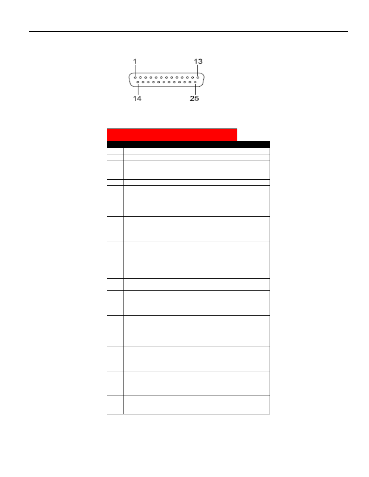
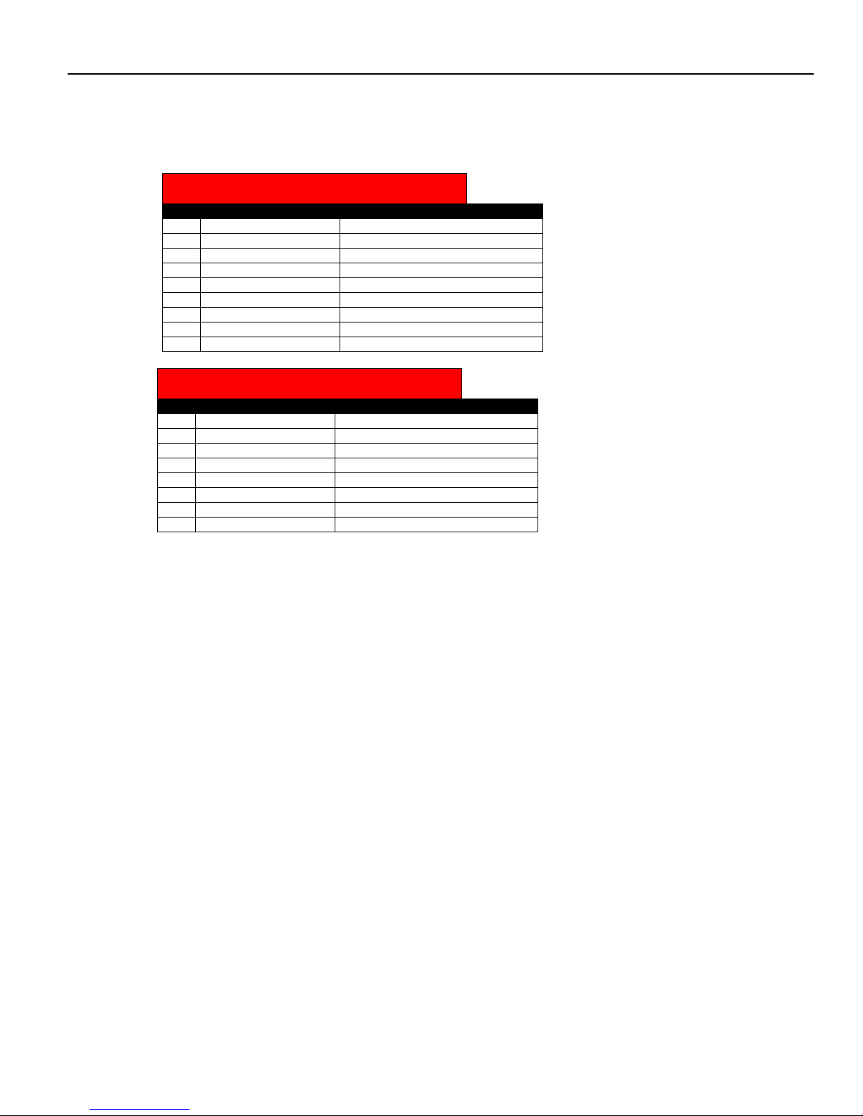
2.5.1 Pin Layout of the Multi interface
The multi signal interface shall have a female 25 pin D-Sub (J1). Twisted pairs shall be used where
applicable. The pin layout is given in Table 2-3.
PIN
SIGNAL
PARAMETERS
1
+24V
+24Vdc±1Vdc @ 4A
2
+24V
+24Vdc±1Vdc @ 4A
3
+24V
+24Vdc±1Vdc @ 4A
4
NC
No connection
5
+24V RETURN
+24V RETURN
6
+24V RETURN
+24V RETURN
7
+24V RETURN
+24V RETURN
8
Signal Ground
Signal Ground
9
Interlock Input
Input, Active low, Interlock is low safe to enable high
voltage. Connect to +24V Return
10
kV Monitor
Output, 0 to 8V = 0 to rated output voltage. Zout=100Ω
11
µA Monitor
Output, 0 to 10V = 0 to rated output current. Zout=100Ω
12
X-Ray Ready status
Output, Active Low,
Open Collector, 24Vdc @ 10mA max
13
X-Ray ON status
Output, Active Low,
Open Collector, 24Vdc @ 10mA max
14
Filament Standby status
Output, Active Low,
Open Collector, 24Vdc @ 10mA max
15
Over Voltage Fault
Output, Active Low,
Open Collector, 24Vdc @ 10mA max
16
Over Current Fault
Output, Active Low,
Open Collector, 24Vdc @ 10mA max
17
ARC Fault
Output, Active Low,
Open Collector, 24Vdc @ 10mA max
18
Filament Current Limit
Fault
Output, Active Low,
Open Collector, 24Vdc @ 10mA max
19
Signal Ground
Signal Ground
20
Interlock Output
Output, Active Low,
Open Collector, 24Vdc @ 10mA max
21
µA Program
Input, 0 to 10V = 0 to rated output current. Zin=10kΩ
22
kV Program
Input, 0 to 8V = 0 to rated output voltage. Zin=10kΩ
23
X-Ray ON Command
Input, Active low,
Low (short)=X-Ray ON
High (open)=X-Ray OFF
Internal pull up resistor to +15V
24
Signal Ground
Signal Ground
25
Over Temp.
Output, Active Low,
Open Collector, 24Vdc @ 10mA max
Table 2-3 Pin layout of multi signal connector
Refer to chapter 3 for detailed requirements and function descriptions.
2.5.2 GROUND CONNECTION
NOTE: THE INSTALLER SHOULD ENSURE THAT ALL CABLE CONNECTIONS TO THE
GENERATOR ARE SECURE, AND ALL CABLES EXTERNAL TO THE GENERATOR
ARE ADEQUATELY PROTECTED AGAINST ACCIDENTAL DISCONNECTION.
Page 20

SPELLMAN HIGH VOLTAGE Installation 2
Installation and Operating Manual – XRB011 Page 2-15 118149-001 REV F
2.5.3 CHASSIS GROUND
The chassis of the XRB011 MONOBLOCK must be grounded to the local earth ground and also to the
tube housing ground.
2.5.4 X-RAY PORT
ENSURE THAT THE EXIT PORT IS PROPERLY MATED TO COLLIMATOR OR SATISFACTORILY
SHIELDED WITH LEAD PLUG TO LIMIT EXPOSURE TO LEAKAGE RADIATION.
X-ray Safety Procedures must be followed when testing this unit. The XRB011 is capable of producing
Lethal Voltages and X-ray Radiation. Only proceed with operation of the HVPS after
Consulting with the Manufacturer and verification of X-Ray setup for the proper precautions.
Reading this entire document.
NEVER OPERATE THIS UNIT WITH AN OPEN X-RAY EXIT PORT.
It is recommended not to allow leakage radiation exceeding 0.5mR/hr at 5cm from any surface of the
MONOBLOCK.
2.6 FINAL CHECKS
The room interface connections may now be completed. Before power on, user needs to check the items
as below finally.
When finished all wiring, check that all connections are tight and secure.
Check that all cables are dressed neatly outside the cabinet, and secured as necessary.
Check the ground connection again.
THIS EQUIPMENT GENERATES DANGEROUS VOLTAGES THAT MAY BE FATAL.
PROPER GROUNDING OF ALL HIGH VOLTAGE EQUIPMENT IS ESSENTIAL.
WARNING X-RAY RADIATION EXPOSURE IS HAZARDOUS
Failure to follow these procedures may void the warranty.
Check the input voltage rating on the nameplate of the supply and make certain that this is the rating of the available
power source. Spellman MONOBLOCK XRB011 operates on 24VDC±1VDC
WARNING
WARNING
Page 21
SPELLMAN HIGH VOLTAGE Installation 2
Installation and Operating Manual – XRB011 Page 2-16 118149-001 REV F
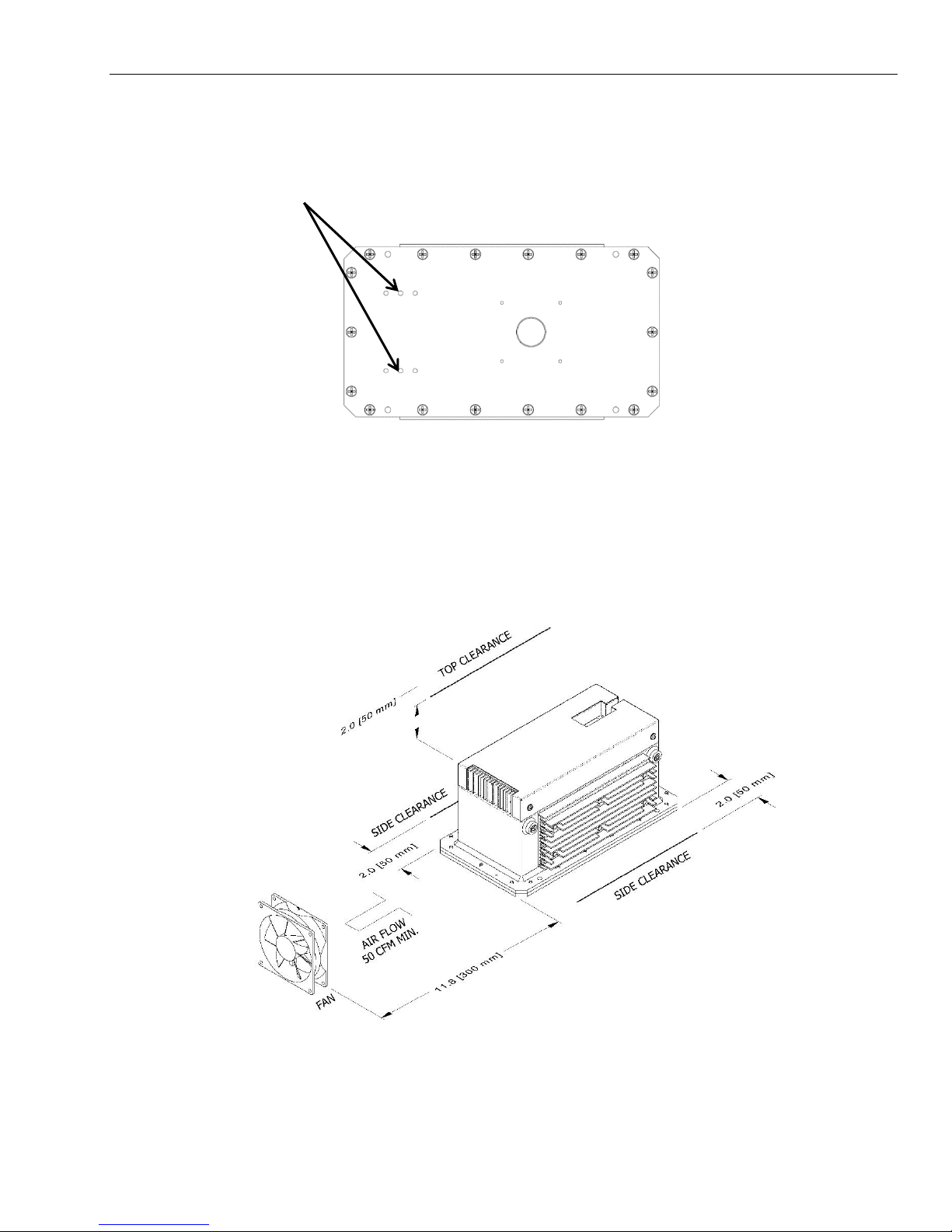
Bellows Vent holes:
Do not block or insert anything into the vent holes located on top cover as shown. These two holes provide venting
for the internal bellows that is used to compensate for the expansion of the oil as the oil temperature varies.
Do not block any vents holes on the cover
Cooling:
A customer supplied minimum 50 CFM fan should be used for the 50W option to maintain safe operating
temperature for MONOBLOCK X-ray generator. The air flow should be direct at the heat sink on the side of the
unit and at the side of the control board compartment. During operation the internal oil temperature should be below
60C and should not exceed 65C. See below Figure for fan location.
FAN
Page 22

SPELLMAN HIGH VOLTAGE Interfacing 3
Installation and Operating Manual – XRB011 Page 3-17 118149-001 REV F
CHAPTER 3
INTERFACING
3.1 INTRODUCTION .............................................................................................................................................................. 18
3.2 LOCAL PROGRAMMING MODE ............................................................................................................................... 18
3.3 LOCAL MONITORS ......................................................................................................................................................... 18
3.5 REMOTE PROGRAMMING MODE ............................................................................................................................ 18
3.6 REMOTE MONITORS ................................................................................................................................................ 18
3.7 XRAY ON COMMAND .............................................................................................................................................. 18
3.8 EXTERNAL INTERLOCK ......................................................................................................................................... 18
3.9 SYSTEM STATUS AND FAULT DIAGNOSTIC DISPLAY ..................................................................................................... 18
3.10 REMOTE MODE (DIGITAL CONTROL) ............................................................................................................................. 19
3.11 CONNECTOR STYLE AND PIN LAYOUT .......................................................................................................................... 20
3.12 SERIAL COMMUNICATION INTERFACE ........................................................................................................................... 21
3.13 RECOMMENDED INTERFACE CIRCUITS (LOCAL MODE, ANALOG INTERFACE) .................................................... 22
3.14 RECOMMENDED INTERFACE CIRCUITS (REMODE MODE, DIGITAL INTERFACE) ........................................... 23
Page 23

SPELLMAN HIGH VOLTAGE Interfacing 3
Installation and Operating Manual – XRB011 Page 3-18 118149-001 REV F
3.1 INTRODUCTION
This Chapter describes the interfacing of the XRB011 MONOBLOCK to the customer system control side,
especially with the serial communication, exposure control switch. Also, exposure mode is introduced with the
timing sequence described as well.
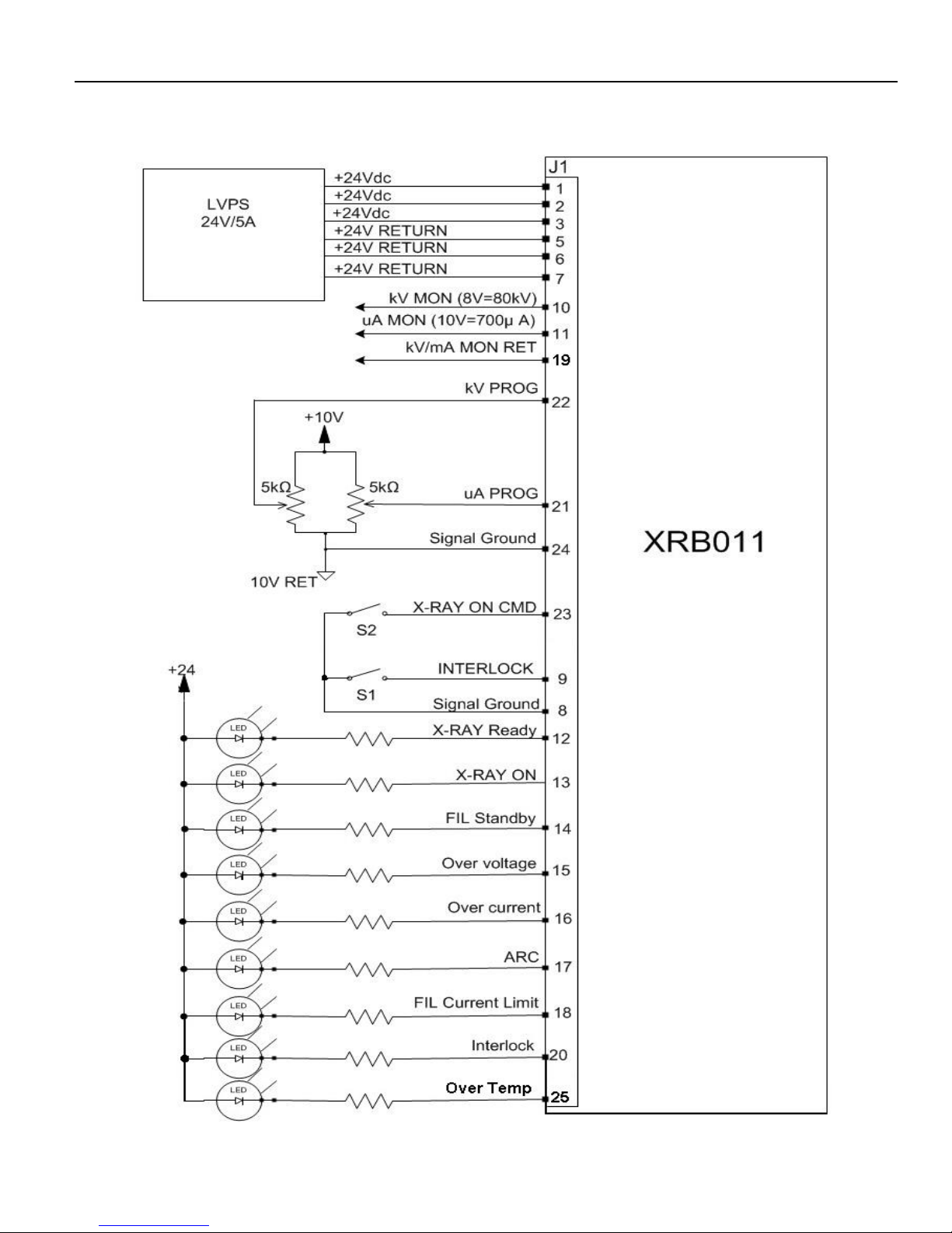
3.2 LOCAL PROGRAMMING MODE
Allows Local adjustment of the output voltage and current via analog voltage inputs on J1 analog interface.
To operate in Local mode, position jumpers for JP11 in the 1-2. JP11 is located on the control board. Remove
the cover to access JP11.
Program kV output value by providing 0-8.00V (0-80kV) to J1-22(reference to signal ground J1-24 or 25).
Program µA output value by providing 0-10.00V (0-250µA for 20W option), (0-700µA for 50W option) to J1-21
(reference to signal ground J1-24 or 25).
All program values default to zero upon power up except kV program to 3.5V (35kV)
3.3 LOCAL MONITORS
Provides local analog monitors for the output voltage and current via analog voltage outputs on J1 analog
interface.
Monitor kV output by measuring J1-10(reference to signal ground J1-24), 0-8.00v (0-80kV).
Monitor µA output by measuring J1-11 (reference to signal ground J1-24 or 25),
0-10.00V (0-250µA,20W option), (0-700µA, 50W option)
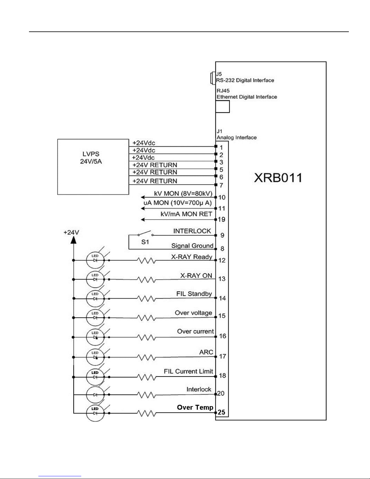
3.5 REMOTE PROGRAMMING MODE
Allows remote adjustment of the output voltage and current via RS- 232 digital interface at J5 or Ethernet digital
interface RJ45
To operate in Remote mode, position jumper JP11 in the 2-3 position on the control board. Remove the cover to
access JP11.
All program values default to zero upon power up except kV program to 35kV.
3.6 REMOTE MONITORS
Provides remote monitors of the output voltage and output current via RS- 232 digital interface at J5 or
Ethernet digital interface RJ45
3.7 XRAY ON COMMAND
Provides control of X-ray ON and X-ray OFF either via a dry contact connection from J1-23 to J1-19 when operating
in Local Mode (analog control). In remote Mode J1-23 is not active and X-ray ON and OFF is controlled through
RS- 232 or Ethernet communication.
The external interlock must also be close for the X-ray to enable.
3.8 EXTERNAL INTERLOCK
The X-ray cannot be enabled unless the external interlock is closed by connecting J1-9 to J1-8. During high voltage
operation, opening the interlock circuit will cause the High Voltage to be disabled.
3.9 SYSTEM STATUS AND FAULT DIAGNOSTIC DISPLAY
If a fault occurs, the power supply will revert to the POWER DOWN mode indicated by X-RAY READY STATUS (J1-
12), RS-232 or Ethernet as HV OFF. In local mode to reset all faults, the X-RAY ON Command (J1-23) must be
toggled OFF and ON. In Remote mode; to reset all faults a host command sent via RS-232 or Ethernet, Reset Faults <52>
.
All fault and status outputs are open collector (Normally off), and are intended to drive an LED or diode of an optocoupler with 24V@10mA max
EXTERNAL INTERLOCK FAULT: Indicates the EXTERNAL INTERLOCK connection is not in closed
position. The fault is indicated by INTLK OPEN via RS-232 or Ethernet as (ARG 9). Analog output signal (J1-20)
is active low (Low = interlock is closed, High = interlock is open)
Page 24

SPELLMAN HIGH VOLTAGE Interfacing 3
Installation and Operating Manual – XRB011 Page 3-19 118149-001 REV F
X-RAY READY STATUS: Indicates that there are no faults and the interlock is closed. The status is
indicated by NO FAULT (X-RAY READY) via RS-232 or Ethernet as (ARG 0). Analog output signal (J1-12) is
active low.
X-RAY ON STATUS: Indicates that the X-RAY is ON or OFF. This status is indicated by via RS-232or
Ethernet as X-RAY ON (ARG 1), X-RAY OFF (ARG 0). Analog output signal (J1-13) is active low (Low X-
RAY is on, High=X-RAY is off).
OVERVOLTAGE FAULT: Indicates the over voltage protection circuitry has caused the high voltage to turn off.
Over voltage protection is internally set to 82kV. This fault is indicated by High kV via RS-232 or Ethernet as (ARG
6), Over Voltage. Analog output signal (J1-15) is active low.
OVER CURRENT FAULT: Indicates the output current has exceeded 275µA (20W option), 710µA (50W option)
or if the allowable percentage of error between actual and programmed emission currents is exceeded resulting in the
HV to be turned off. This fault is indicated by High mA via RS-232or Ethernet as (ARG 3). Analog output signal
(J1-16) is active low.
ARC FAULT: Indicates that an arc has occurred. Occurrences of one arc will shutdown the high voltage and
latched. This fault is indicated by ARC FAULT via RS-232 or Ethernet as (ARG 2). Analog output signal (J1-17)
active low.
UNDER VOLTAGE FAULT: Indicates a failure in the voltage regulation circuitry less than <35kV. This fault
occurs when there is a lack of output power to maintain regulation and will result in shutdown of the HV. This fault is
indicated by via RS-232 or Ethernet as (ARG 4). There is no analog output signal.
FILAMENT CURRENT LIMIT FAULT: Indicates the filament current exceeded the safe operating current of the
X-Ray tube. This fault is indicated by FILAMENT LIMIT via RS-232 or Ethernet as (ARG 10). Analog output
signal (J1- 18) is active low.
FILAMENT STANDBY STATUS: Indicates the X-RAY is off and the filament current is in standby mode. This
status is indicated by FILAMENT STANDBY via RS-232 or Ethernet as (ARG 11). Analog output signal (J1-14) is
active low.
WATCHDOG TIMER: Indicates the host computer has lost communication and with the HVPS system for a period
greater than ten second. This feature is enabled via RS-232 host command. This fault is indicated via RS-232 as
(ARG 7) Watchdog Time- out. See digital manual for details.
OVER TEMPERATURE: Indicates that the internal oil temperature has exceeded 65 degree C.
3.10 REMOTE MODE (DIGITAL CONTROL)
G.U.I Installation software will be provided up on request.
Start the G.U.I.
Read agreement then click AGREES...
Page 25
SPELLMAN HIGH VOLTAGE Interfacing 3
Installation and Operating Manual – XRB011 Page 3-20 118149-001 REV F
3.11 J1 CONNECTOR STYLE AND PIN LAYOUT
Figure 3-1 multi signal interface connector
Table 3-2 Pin layout of multi signal interface
PIN
SIGNAL
PARAMETERS
1
+24V
+24Vdc±1Vdc @ 4A
2
+24V
+24Vdc±1Vdc @ 4A
3
+24V
+24Vdc±1Vdc @ 4A
4
NC
No connection
5
+24V RETURN
+24V RETURN
6
+24V RETURN
+24V RETURN
7
+24V RETURN
+24V RETURN
8
Signal Ground
Signal Ground
9
Interlock Input
Input, Active low, Interlock is low safe
to enable high voltage. Connect to
+24V Return
10
kV Monitor
Output, 0 to 8V = 0 to rated output
voltage. Zout=100Ω
11
µA Monitor
Output, 0 to 10V = 0 to rated output
current. Zout=100Ω
12
X-Ray Ready status
Output, Active Low,
Open Collector, 24Vdc @ 10mA max
13
X-Ray ON status
Output, Active Low,
Open Collector, 24Vdc @ 10mA max
14
Filament Standby status
Output, Active Low,
Open Collector, 24Vdc @ 10mA max
15
Over Voltage Fault
Output, Active Low,
Open Collector, 24Vdc @ 10mA max
16
Over Current Fault
Output, Active Low,
Open Collector, 24Vdc @ 10mA max
17
ARC Fault
Output, Active Low,
Open Collector, 24Vdc @ 10mA max
18
Filament Current Limit
Fault
Output, Active Low,
Open Collector, 24Vdc @ 10mA max
19
Signal Ground
Signal Ground
20
Interlock Output
Output, Active Low,
Open Collector, 24Vdc @ 10mA max
21
µA Program
Input, 0 to 10V = 0 to rated output
current. Zin=10kΩ
22
kV Program
Input, 0 to 8V = 0 to rated output
voltage. Zin=10kΩ
23
X-Ray ON Command
Input, Active low,
Low (short)=X-Ray ON
High (open)=X-Ray OFF
Internal pull up resistor to +15V
24
Signal Ground
Signal Ground
25
Over Temp.
Output, Active Low,
Open Collector, 24Vdc @ 10mA max
Page 26
SPELLMAN HIGH VOLTAGE Interfacing 3
Installation and Operating Manual – XRB011 Page 3-21 118149-001 REV F
3.12 SERIAL COMMUNICATION INTERFACE
The serial communication is part of the Multi Signal Interface
The pin definition shows below:
PIN
SIGNAL
PARAMETERS
1
NC
No connection
2
TX Out
Transmit Data
3
RX In
Receive Data
4
NC
No connection
5
SGND
Signal Ground
6
NC
No connection
7
NC
No connection
8
NC
No connection
9
NC
No connection
PIN
SIGNAL
PARAMETERS
1
TX+
Transmit Data +
2
TX -t
Transmit Data -
3
RX +
Receive Data +
4
NC
No connection
5
NC
No connection
6
RX-
Receive Data -
7
NC
No connection
8
NC
No connection
User should connect a straight type RS232 cable properly with system side such as PC. Twisted wires are
preferable to enhance the EMC performance.
GUI software can be used temporarily to test the XRB011 provided per request installed on the user PC.
(Refer to separate document for detailed information of GUI). But user need to develop their own ultimate
software based on open protocol (Refer to separate document) and design system control board to integrated
XRB011 into their system with proper method (Refer to 2.6.1 NOTE the isolation requirement).
Page 27
SPELLMAN HIGH VOLTAGE Interfacing 3
Installation and Operating Manual – XRB011 Page 3-22 118149-001 REV F
3.13 RECOMMENDED INTERFACE CIRCUITS (LOCAL MODE, ANALOG INTERFACE)
Page 28
SPELLMAN HIGH VOLTAGE Interfacing 3
Installation and Operating Manual – XRB011 Page 3-23 118149-001 REV F
3.14 RECOMMENDED INTERFACE CIRCUITS (REMODE MODE, DIGITAL INTERFACE)
Monitors and Fault LED’s are optional
Page 29

SPELLMAN HIGH VOLTAGE Trouble Shooting 4
Installation and Operating Manual – XRB011 Page 4-24 118149-001 REV F
CHAPTER 4
TROUBLE SHOOTING
CONTENTS:
Section Title
4.1 INTRODUCTION ........................................................................................................................................................ 25
4.2 STATUS AND ERROR CODES.................................................................................................................................. 25
4.2.1 Status Messages ....................................................................................................................................................... 25
TABLE 1 – GUIDANCE AND MANUFACTURER’S DECLARATION ............................................................................................ 25
ELECTROMAGNETIC EMISSIONS – FOR ALL ME EQUIPMENT AND ME SYSTEMS ...................................................... 25
TABLE 2 – GUIDANCE AND MANUFACTURER’S DECLARATION
ELECTROMAGNETIC EMISSIONS – FOR ALL ME EQUIPMENT AND ME SYSTEMS ...................................................... 26
TABLE 3 – GUIDANCE AND MANUFACTURER’S DECLARATION
ELECTROMAGNETIC IMMUNITY – FOR ME EQUIPMENT AND ME SYSTEMS THAT ARE NOT LIFE-SUPPORING ........... 26
TABLE 4 – RECOMMENDED SEPARATION DISTANCES BETWEEN PORTABLE AND MOBILE RF COMMUNICATIONS EQUIPMENT
AND THE ME EQUIPMENT OR ME SYSTEM – FOR ME EQUIPMENT AND ME SYSTEMS THAT ARE NOT LIFE- ............... 27
Page 30
SPELLMAN HIGH VOLTAGE Trouble Shooting 4
Installation and Operating Manual – XRB011 Page 4-25 118149-001 REV F
4.1 INTRODUCTION
Fault or error message will be indicated via system status indicator or serial message during abnormal
operation. This Chapter contains tables of those messages and suggests actions to be taken by service
personnel to correct any malfunctions that may occur.
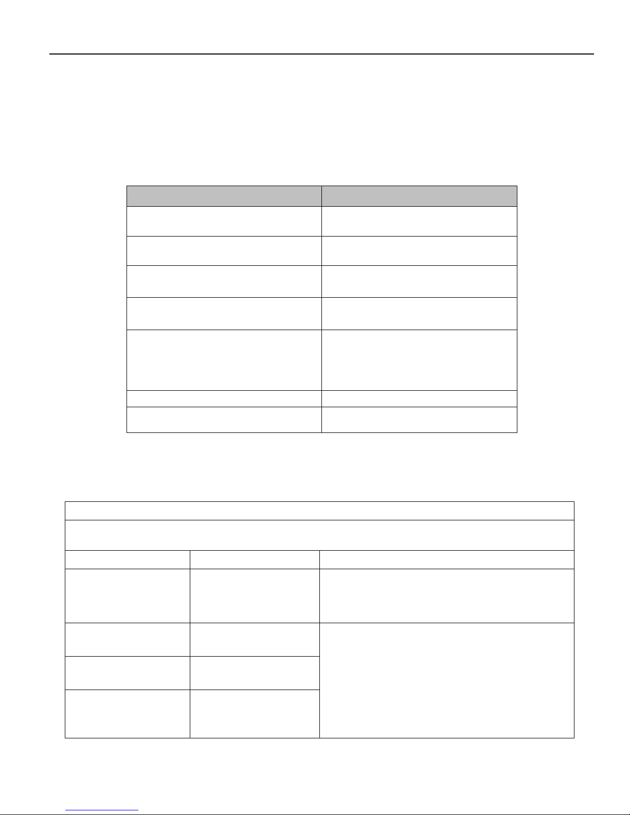
4.2 STATUS AND ERROR CODES
4.2.1 Status Messages
Fault/Symptom
Possible Cause
OV led illuminated and Over voltage fault at RS-232
resulting in HV Status Off.
kV programming set greater than 82kV.
UV led illuminated and Under Voltage fault at RS-232
resulting in HV Status Off.
kV programming set less than 35kV.
OC led illuminated and Over Current fault at RS-232
resulting in HV Status Off.
mA programming greater than 275µA (20W option)
710µA (50W option)
UC led illuminated and Under Current fault at RS-232
resulting in no emission, HV Status Off.
Occurrence of filament of the tube breaks open.
ARC FLT led illuminated and Arc fault at RS-232
resulting in HV Status OFF
Occurrence of tube arc causing shutdown. Clear fault
and send X-ray command. Refer to tube re-seasoning
procedure Table 2 and idle times. If problem continues
contact Spellman service department.
Unit will not Enable
Interlock open
OT led illuminated and Over Temp fault at RS-232
resulting in HV Status Off.
Tank oil temperature has exceeded 65 degrees C
TABLE 1 – GUIDANCE AND MANUFACTURER’S DECLARATION
ELECTROMAGNETIC EMISSIONS – FOR ALL ME EQUIPMENT AND ME SYSTEMS
Guidance and manufacturer’s declaration – electromagnetic emissions
The XRB011 is intended for use in the electromagnetic environment specified below. The customer or the
user of the XRB011 should assure that it is used in such an environment.
Emissions test
Compliance
Electromagnetic environment – guidance
RF emissions
CISPR 11
Group 2
The XRB011 uses RF energy only for its internal
function. Therefore, its RF emissions are very low
and are not likely to cause any interference in nearby
electronic equipment.
RF emissions
CISPR 11
Class B
The XRB011 is suitable for use in all establishments
other than domestic and those directly connected to
the public low-voltage power supply network that
supplies buildings used for domestic purposes.
Harmonic emissions
IEC 61000-3-2
Not applicable
Voltage fluctuations/
flicker emissions
IEC 61000-3-3
Not applicable
Page 31

SPELLMAN HIGH VOLTAGE Trouble Shooting 4
Installation and Operating Manual – XRB011 Page 4-26 118149-001 REV F
TABLE 2 – GUIDANCE AND MANUFACTURER’S DECLARATION – ELECTROMAGNETIC EMISSIONS – FOR
ALL ME EQUIPMENT AND ME SYSTEMS
Guidance and manufacturer’s declaration – electromagnetic immunity
The XRB011 is intended for use in the electromagnetic environment specified below. The customer or the
user of the XRB011 should assure that it is used in such an environment.
Immunity test
IEC 60601 test level
Compliance level
Electromagnetic environment – guidance
Electrostatic
discharge
(ESD)
IEC 61000-4-2
±6 kV contact
±8 kV air
±6 kV contact
±8 kV air
Floors should be wood, concrete or ceramic
tile. If floors are covered with synthetic
material, the relative humidity should be at
least 30 %.
Electrical fast
transient/burst
IEC 61000-4-4
±2 kV for power
supply lines
±1 kV for input/output
lines
±2 kV for power
supply lines
±1kV for
input/output
lines
Mains power quality should be that of a
typical commercial or hospital environment.
Surge
IEC 61000-4-5
Not applicable
Not applicable
Mains power quality should be that of a
typical commercial or hospital environment.
Voltage dips,
short
interruptions
and
voltage
variations
on power
supply
input lines
IEC 61000-4-11
Not applicable
Not applicable
Mains power quality should be that of a
typical commercial or hospital environment.
If the user of the XRB011 requires
continued operation during power mains
interruptions, it is recommended that the
XRB011 be powered from an uninterruptible
power supply or a battery.
Power
frequency
(50/60 Hz)
magnetic field
IEC 61000-4-8
3 A/m
3 A/m
Power frequency magnetic fields should be
at levels characteristic of a typical location
in a typical commercial or hospital
environment.
NOTE UT is the A.C. mains voltage prior to application of the test level.
TABLE 3 – GUIDANCE AND MANUFACTURER’S DECLARATION – ELECTROMAGNETIC IMMUNITY – FOR ME
EQUIPMENT AND ME SYSTEMS THAT ARE NOT LIFE-SUPPORING
Guidance and manufacturer’s declaration – electromagnetic immunity
The XRB011 is intended for use in the electromagnetic environment specified below. The customer or the user of the
XRB011 should assure that it is used in such an environment.
Immunity test
IEC 60601 test level
Compliance level
Electromagnetic environment – guidance
Portable and mobile RF communications equipment
should be used no closer to any part of the XRB011,
including cables, than the recommended separation
distance calculated from the equation applicable to
the frequency of the transmitter.
Page 32

SPELLMAN HIGH VOLTAGE Trouble Shooting 4
Installation and Operating Manual – XRB011 Page 4-27 118149-001 REV F
Recommended separation distance
Conducted RF
IEC 61000-4-6
3 Vrms
150 kHz to 80 MHz
3 Vrms
d = 1.17 √P
Radiated RF
IEC 61000-4-3
3 V/m
80 MHz to 2.5 GHz
3 V/m
d = 1.17 √P 80 MHz to 800 MHz
d = 2.33 √P 800 MHz to 2.5 GHz
Where P is the maximum output power rating of the
transmitter in watts (W) according to the transmitter
manufacturer and d is the recommended separation
distance in meters (m).
Field strengths from fixed RF transmitters, as
determined by an electromagnetic site survey,a
should be less than the compliance level in each
frequency range.b
Interference may occur in the vicinity of equipment
marked with the following symbol:
NOTE 1 At 80 MHz and 800 MHz, the higher frequency range applies.
NOTE 2 These guidelines may not apply in all situations. Electromagnetic propagation is affected by absorption and
reflection from structures, objects and people.
a Field strengths from fixed transmitters, such as base stations for radio (cellular/cordless) telephones and land mobile
radios, amateur radio, AM and FM radio broadcast and TV broadcast cannot be predicted theoretically with accuracy. To
assess the electromagnetic environment due to fixed RF transmitters, an electromagnetic site survey should be
considered. If the measured field strength in the location in which the XRB011 is used exceeds the applicable RF
compliance level above, the XRB011 should be observed to verify normal operation. If abnormal performance is observed,
additional measures may be necessary, such as re-orienting or relocating the XRB011.
b Over the frequency range 150 kHz to 80 MHz, field strengths should be less than 3 V/m.
TABLE 4 – RECOMMENDED SEPARATION DISTANCES BETWEEN PORTABLE AND MOBILE RF
COMMUNICATIONS EQUIPMENT AND THE ME EQUIPMENT OR ME SYSTEM – FOR ME
EQUIPMENT AND ME SYSTEMS THAT ARE NOT LIFE-SUPPORTING
Recommended separation distances between portable and mobile RF communications equipment
and the XRB011
The XRB011 is intended for use in an electromagnetic environment in which radiated RF disturbances are
controlled. The customer or the user of the XRB011 can help prevent electromagnetic interference by
maintaining a minimum distance between portable and mobile RF communications equipment (transmitters)
and the XRB011 as recommended below, according to the maximum output power of the communications
equipment.
Rated maximum
output
power of
transmitter
W
Separation distance according to frequency of transmitter
m
150 kHz to 80 MHz
d = 1.17 √P
80 MHz to 800 MHz
d = 1.17 √P
800 MHz to 2,5 GHz
d = 2.33 √P
0.01
0.117
0.117
0.233
0.1
0.370
0.370
0.737
Page 33

SPELLMAN HIGH VOLTAGE Trouble Shooting 4
Installation and Operating Manual – XRB011 Page 4-28 118149-001 REV F
1
1.17
1.17
2.33
10
3.70
3.70
7.37
100
11.7
11.7
23.3
For transmitters rated at a maximum output power not listed above, the recommended separation distance d
in meters (m) can be determined using the equation applicable to the frequency of the transmitter, where P
is the maximum output power rating of the transmitter in watts (W) according to the transmitter
manufacturer.
NOTE 1 At 80 MHz and 800 MHz, the separation distance for the higher frequency range applies.
NOTE 2 These guidelines may not apply in all situations. Electromagnetic propagation is affected by
absorption and reflection from structures, objects and people.
Page 34

SPELLMAN HIGH VOLTAGE Schematics 5
Installation and Operating Manual – XRB011 Page 5-29 118149-001 REV F
CHAPTER 5
SCHEMATICS
CONTENTS:
5.1 INTRODUCTION ........................................................................................................................................................ 30
5.2 FUNCTIONAL SCHEMATIC INDEX ........................................................................................................................ 30
Page 35

SPELLMAN HIGH VOLTAGE Schematics 5
Installation and Operating Manual – XRB011 Page 5-30 118149-001 REV F
5.1 INTRODUCTION
This chapter contains the functional schematics for XRB011 MONOBLOCK. Each schematic represents a
major function in the generator; the 2 functional schematics in this chapter represent all of the major
functional blocks in this generator.
5.2 FUNCTIONAL SCHEMATIC INDEX
The following functional schematics are not included in this manual.
DESCRIPTION
DRAWING NUMBER #
Block diagram Schematic
441431-001
Control Board Schematic
441434-001
Page 36

To obtain information on Spellman’s product warranty please visit our website at:
http://www.spellmanhv.com/en/About/Warranty.aspx
Page 37

XRB011 Digital Interface
Serial RS-232 - Ethernet
Copyright 2014, Spellman High Voltage Electronics Corporation. All Rights Reserved.
This information contained in this publication is derived in part from proprietary and patent data. This information has
been prepared for the express purpose of assisting operating and maintenance personnel in the efficient use of the
model described herein, and publication of this information does not convey any right to reproduce it or to use it for
any purpose other than in connection with installation, operation, and maintenance of the equipment described.
118150-001 REV. B
Page 38

Changes
REVISION DATE DESCRIPTION
1 09/18/13 Draft version
2 04/18/14 Added Ramp Time command description
Added User Configuration command.
3 05/14/14 Deleted mA Low fault, changed HV to X-RAY,
Update status table.
4 03/28/16 Added Over temperature fault to command 22.
118150-001 REV. B Page 2 of 66
Page 39

Table Of Contents
1.0 SCOPE ................................................................................................................. 5
2.0 FUNCTIONAL DESCRIPTION ............................................................................. 5
3.0 RS232 .................................................................................................................. 5
3.1 RS232 INTERFACE ....................................................................................................... 5
3.2 RS-232 CABLING .......................................................................................................... 6
3.3 Programming the RS-232 Interface ...................................................................................... 7
3.3.1 Enabling Communications Objects in Visual Basic for RS-232 ........................... 7
3.3.2 Configuring Communications in Visual Basic for RS-232 .................................... 7
3.4 SERIAL INTERFACE PROTOCOL .............................................................................. 8
3.4.1 COMMAND ARGUMENTS ................................................................................... 8
3.4.2 CHECKSUMS ........................................................................................................... 8
3.4.3 COMMAND OVERVIEW ..................................................................................... 11
3.4.4 RESPONSE OVERVIEW ...................................................................................... 12
3.4.5 COMMANDS DESCRIPTION ............................................................................. 13
3.4.6 SERIAL COMMAND HANDLING ................................................................. 29
4.0 ETHERNET ........................................................................................................ 30
4.1 ETHERNET INTERFACE .......................................................................................... 30
4.2 ETHERNET CABLING ............................................................................................... 30
4.3 ETHERNET WEB SERVER ........................................................................................ 32
4.3.1 Diagnostic Web Server ........................................................................................... 32
4.3.2 Web Pages ................................................................................................................ 32
4.4 Direct Connection between the DXM and a Computer ................................................ 39
4.5 Configuring the Computer for Direct Ethernet Connection .......................................... 39
4.6 Testing a Direct Connection ......................................................................................... 42
4.7 Configuring the XRB011 For a Local Area Network (LAN) ...................................... 43
4.8 Configuring the Network Settings from the Monitor and Configure Applet ................ 43
4.9 Enabling Communications Objects in Visual Basic for Ethernet Communications ..... 45
4.10 Configuring Communications in Visual Basic for Ethernet ......................................... 45
4.11 TCP/IP FORMAT ......................................................................................................... 47
4.12 COMMAND ARGUMENTS ....................................................................................... 48
4.13 COMMAND OVERVIEW ........................................................................................... 49
4.14 RESPONSE OVERVIEW ............................................................................................ 50
4.15 COMMANDS DESCRIPTION .................................................................................... 51
4.15.1 Set KV <10> .............................................................................................................. 51
4.15.2 Set MA <11> ............................................................................................................. 52
4.15.3 Request KV Set point <14> ..................................................................................... 53
4.15.4 Request MA Set point <15> .................................................................................... 54
4.15.5 Request Status <22>................................................................................................. 55
4.15.6 Request Firmware Version <23> ............................................................................ 56
4.15.7 Request Model Number <26> ................................................................................ 57
4.15.8 Tickle Watchdog <27> ............................................................................................. 58
4.15.9 Enable Watchdog <28> .......................................................................................... 59
118150-001 REV. B Page 3 of 66
Page 40

4.15.12 Reset Faults <52> .................................................................................................. 62
4.15.13 Get KV Monitor <60> ............................................................................................ 63
4.15.14 Get MA monitor <61> ........................................................................................... 64
4.15.15 Get X-RAY Status <98> ........................................................................................ 65
4.15.16 Turn High X-RAY On/Off <99> ......................................................................... 66
118150-001 REV. B Page 4 of 66
Page 41

WARNING
THIS EQUIPMENT GENERATES DANGEROUS VOLTAGES THAT MAY BE FATAL.
PROPER GROUNDING OF ALL HIGH VOLTAGE EQUIPMENT IS ESSENTIAL.SEE 80kv
MONOBlOCK OWNERS MANUAL FOR PROPER GROUNDING TECHNIQUE AND SAFETY
PRECAUTIONS BEFORE APPLING AC INPUT POWER TO THE XRB UNIT.
TO PREVENT DAMAGE TO THE HOST COMPUTER THE COMPUTER SHOULD BE
GROUNDED TO THE SAME GROUND AS THE UUT.
This unit is capable of producing X-ray radiation, please proceed only after
proper precautions have been taken to prevent X-ray exposure.
1.0 SCOPE
This document applies to the communications interfaces on the XRB, assembly
460162.
2.0 FUNCTIONAL DESCRIPTION
The XRB provides 2 types of digital communications interface:
RS-232 on J3
Ethernet
3.0 RS232
3.1 RS232 INTERFACE
The RS232C interface has the following attributes:
115K bits per second
No Parity
8 Data Bits
1 Stop Bit
No handshaking
DB-9 connector as shown
Figure 1 – J3, RS-232 DB-9M pinout (front view)
118150-001 REV. B Page 5 of 66
Page 42

PIN
DESCRIPTION
1 - 2
Tx Out
3
Rx In 4 -
5
Ground
6 - 7 - 8 - 9
-
PC to XRB Board Cable Details
PC Connector (DB-9 Female)
XRB Connector (DB-9 Male)
Pin 2: RX In
Pin 2: TX Out
Pin 3: TX Out
Pin 3: RX In
Pin 5: Ground
Pin 5: Ground
3.2 RS-232 CABLING
A standard shielded RS-232 cable is used to connect the XRB serial port
to the serial port on a standard personal computer. Please refer to the
following chart.
118150-001 REV. B Page 6 of 66
Page 43

3.3 Programming the RS-232 Interface
This section details how to create software to control the XRB011 serial
interface.
The RS-232 interface makes use of a standard ‘command/response’
communications protocol. See section 3.4 for a description of the serial
interface protocol.
All software that addresses the RS-232 interface must adhere to the
following parameters:
A default Baud rate of 115.2K bps
No Parity
8 Data Bits
1 Stop Bit
No handshaking
3.3.1 Enabling Communications Objects in Visual Basic for RS-232
Communications in Microsoft Visual Basic 6.0 are directed to a control
that abstracts the port. In the case of serial interface we need
Microsoft Comm Control 6.0. To enable this in your VB 6 project, go to:
Project -> Components
Then in the list make sure that Microsoft Comm Control 6.0 has a
check next to it. The Comm Control Object should then appear in your
toolbox. It will have an icon of a telephone and will be named:
MSComm. This can be dragged and dropped into your application.
You will then need to set the object’s properties.
3.3.2 Configuring Communications in Visual Basic for RS-232
In order to configure the MSComm Object, first you must initialize it
in the Object properties:
Settings 115200,n,8,1
Handshaking 0 – comNone
The application can be set to either default to a specific COM Port
or the End User can be allowed to choose one for the particular
PC. For the “Default” scenario, include the following commands in
the Form_Load() routine:
118150-001 REV. B Page 7 of 66
Page 44

MSComm1.CommPort = portNumber
MSComm1.PortOpen = True
3.4 SERIAL INTERFACE PROTOCOL
Serial communications will use the following data format::
<STX><CMD><,>ARG><,><CS><ETX>
Where:
<STX> = 1 ASCII 0x02 Start of Text character
<CMD> = 2 ASCII characters representing the command ID
<,> = 1 ASCII 0x2C character
<ARG> = Command Argument
<,> = 1 ASCII 0x2C character
<CS> = Checksum
<ETX> = 1 ASCII 0x03 End of Text character
3.4.1 COMMAND ARGUMENTS
The format of the numbers is a variable length string. To represent the
number 42, the string ‘42’, ‘042’, or ‘0042’ can be used. This being the
case, commands and responses that carry data are variable in length.
3.4.2 CHECKSUMS
The checksum is computed as follows:
Add the <CMD>, <,>, and <ARG>, and <,> bytes into a 16 bit (or larger)
word. The bytes are added as unsigned integers.
Take the 2’s complement (negate it).
Truncate the result down to the eight least significant bits.
Clear the most significant bit (bit 7) of the resultant byte, (bitwise AND with
0x7F).
Set the next most significant bit (bit 6) of the resultant byte (bitwise OR
with 0x40).
Using this method, the checksum is always a number between 0x40 and 0x7F.
The checksum can never be confused with the <STX> or <ETX> control
characters, since these have non-overlapping ASCII values.
118150-001 REV. B Page 8 of 66
Page 45

If the DSP detects a checksum error, the received message is ignored – no
acknowledge or data is sent back to the host. A timeout will act as an implied
NACK.
Here is another example, this time for command 22 (Request Status) which has
no arguments.
The original message with a placeholder for checksum is:
<STX>22,<CS><ETX>
First, you add up all the characters starting with the ‘2’ in the command number
to the comma before the checksum with their ASCII values (in hexadecimal):
0x32 + 0x32 + 0x2C = 0x90
Next, you then take the two’s complement of that number by negating it, by
subtracting it from 0x100 (decimal 256), and only retain the lowest 7 bits by
bitwise ANDing the results with 0x7F:
This combines the steps of getting the twos complement, truncating the result to
8 bits and clearing the 8th bit.
(0x100 – 0x90) & 0x7F = 0x70
Finally, bitwise OR the result with 0x40:
0x70 | 0x40 = 0x70
The checksum byte is 0x70 (Decimal 112, ASCII: p)
The following is sample code, written in Visual Basic, for the generation of
checksums:
Public Function ProcessOutputString(outputString As String) As String
Dim i As Integer
Dim CSb1 As Integer
Dim CSb2 As Integer
Dim CSb3 As Integer
Dim CSb$
Dim X
X = 0
For i = 1 To (Len(outputString)) 'Starting with the CMD character
X = X + Asc(Mid(outputString, i, 1)) 'adds ascii values together
Next i
CSb1 = 256 - X 'Twos Complement
CSb2 = 63 And (CSb1)
CSb3 = 64 Or (CSb2) 'OR 0x40
CSb$ = Chr(Val("&H" & (Hex(CSb3))))
118150-001 REV. B Page 9 of 66
Page 46

ProcessOutputString = Chr(2) & outputString & CSb$ & Chr(3)
End Function
Here is an example of an actual Checksum calculation for command 10
(Program kV set point)
The original message with a placeholder for the checksum is
<STX>10,4095,<CS><ETX>
First, you add up all the characters starting with the ‘1’ in the command number,
to the comma before the checksum with their ASCII values (in hexadecimal):
0x31 + 0x30 + 0x2C + 0x34 + 0x30 + 0x39 + 0x35 + 0x2C = 0x18B
Next, you then take the two’s complement of that number by negating it, by
subtracting it from 0x100 (decimal 256), and only retain the lowest 7 bits by
bitwise ANDing the results with 0x7F. :
This combines the steps of getting the twos complement, truncating the result to
8 bits and clearing the 8th bit.
(0x100 – 0x18B) & 0x7F = 0x75
Finally, bitwise OR the result with 0x40:
0x75 | 0x40 = 0x75
The checksum byte is 0x75 (Decimal 117, ASCII: u)
118150-001 REV. B Page 10 of 66
Page 47

Command Name
<CMD>
<ARG>
RANGE
Set KV
10
1-4 ASCII
0-Max KV
Set MA
11
1-4 ASCII
0-Max mA
Request KV Setpoint
14
None
Request MA Setpoint
15
None
-
Request Status
22
None
-
Request Software
Version
23
None
-
Request Model
Number
26
None
-
Tickle Watchdog
27
None
-
Enable Watchdog
28
1-2 ASCII
1-10
Ramp Time
29
1-4 ASCII
1 - 1000
User Configuration
31
4 ASCII
-
Reset Faults
52
None
-
Get KV monitor
60
None
-
Get MA monitor
61
None
-
Get X-RAY Status
98
None
-
Turn X-RAY
ON/OFF
99
1 ASCII
0 or 1
3.4.3 COMMAND OVERVIEW
118150-001 REV. B Page 11 of 66
Page 48

Response Name
<CMD>
<ARG>
Request KV
Setpoint
14
1-3 ASCII
Request MA
Setpoint
15
1-3 ASCII
Request Status
22
3 ASCII
Request DSP
Software Version
23
11 ASCII
Request Model
number
26
5 ASCII
Get KV monitor
60
1-3 ASCII
Get MA monitor
61
1-3 ASCII
Get X-RAY Status
98
1 ASCII
3.4.4 RESPONSE OVERVIEW
The command responses will follow the same format as outlined above in
section 2.1. This list is comprised of Commands with complex responses
only. Commands using a simple response will use the <$> character
(ASCII 0x24) as a “Success” response or a single character error code.
These responses will be eight ASCII characters in length.
118150-001 REV. B Page 12 of 66
Page 49

3.4.5 COMMANDS DESCRIPTION
3.4.5.1 Set KV <10>
Description:
The host requests that the firmware change the KV set point.
Direction:
Host to supply
Syntax:
<STX><10><,><ARG><,><CS><ETX>
Where:
<ARG> = Value of KV in ASCII format. Units are tenths of KV. Example,
for 80KV, enter 800.
Example:
<STX>10,800,<CS><ETX>
Response:
<STX><10><,><$><,><CS><ETX> or
<STX><10><,><ARG><,><CS><ETX>
where <ARG> = error code
Error Codes: 1 = receive error, 2 = unrecognized command
118150-001 REV. B Page 13 of 66
Page 50

3.4.5.2 Set MA <11>
Description:
The host requests that the firmware change the MA set point.
Direction:
Host to supply
Syntax:
<STX><11><,><ARG><,><CS><ETX>
Where:
<ARG> = Value of mA in ASCII format. Units are micro amps. Example,
For 0.2 mA, enter 200.
Example:
<STX>11,200,<CS><ETX>
Response:
<STX><11><,><$><,><CS><ETX>
<STX><11><,><ARG><,><CS><ETX>
where <ARG> = error code
Error Codes: 1 = receive error, 2 = unrecognized command
118150-001 REV. B Page 14 of 66
Page 51

3.4.5.3 Request KV Set point <14>
Description:
The host requests the KV set point.
Direction:
Host to supply
Syntax:
<STX><14><,><ETX>
Example:
<STX>14,<ETX>
Response:
<STX><14><,><ARG><,><ETX>
Where <ARG> = number in ASCII format representing un-scaled KV set
point. Units are tenths of KV.
118150-001 REV. B Page 15 of 66
Page 52

3.4.5.4 Request MA Set point <15>
Description:
The host requests that the firmware send the MA set point.
Direction:
Host to supply
Syntax:
<STX><15><,><ETX>
Example:
<STX>15,<ETX>
Response:
<STX><15><,><ARG><,><ETX>
Where <ARG> = = number in ASCII format representing un-scaled mA
set point. Units are micro amps.
118150-001 REV. B Page 16 of 66
Page 53

Arg
Name
Description
000
No Fault (X-RAY Ready)
It indicates thet the Monoblock is ready to produce X-RAY
001
Over Temperature
It indicates oil tank over temperature
002
Arc Fault
It indicates that an arc event was detected
003
High mA
The mA output is higher than allowed threshold
005
Low kV
The kV output is lower than threshold
006
High kV
The kV output is higher than allowed theshold
007
Watchdog
Watchdog timer expired while X-Rays were on
009
Interlock Open
Interlock is not satisfied
010
Filament Limit
Indicates filament overcurrent
011
Filament Standby
Filament status
3.4.5.5 Request Status <22>
Description:
The host requests that the firmware sends the power supply status. The
power supply sends a three digits code representing a specific status
condition. A description of these characters is shown in the table below.
Direction:
Host to supply
Syntax:
<STX><22><,><CS><ETX>
Example:
<STX>22,<CS><ETX>
Response:
<STX><22><,><ARG><,><CS><ETX>
Example:
<STX>22,000,<CS><ETX>
118150-001 REV. B Page 17 of 66
Page 54

3.4.5.6 Request Firmware Version <23>
Description:
The host requests that the firmware sends the DSP firmware version.
Direction:
Host to supply
Syntax:
<STX><23><,><CS><ETX>
Example:
<STX>23,<CS><STX>
Response:
<STX><23><,>< ARG><,><CS><ETX>
Where:
<ARG> consists of eleven ASCII characters representing the current
firmware part number/version. The format is SWMNNNN-NNN, where N is
a numeric character.
Example:
<STX>23,SWM0584-001,<CS><ETX>
118150-001 REV. B Page 18 of 66
Page 55

3.4.5.7 Request Model Number <26>
Description:
The host requests that the firmware sends the unit model number
Direction:
Host to supply
Syntax:
<STX><26><,><CS><ETX>
Example:
<STX>26,<CS><ETX>
Response:
<STX><26><,><ARG><,><CS><ETX>
Where:
<ARG> consists of five ASCII characters representing the model number.
The format is XNNNN, where N is a numeric character.
Example:
<STX>26,X4618,<CS><ETX>
118150-001 REV. B Page 19 of 66
Page 56

3.4.5.8 Tickle Watchdog <27>
Description:
This command is used to reset the Watchdog timer to prevent a watchdog
time out fault condition.
Direction:
Host to supply
Syntax:
<STX><27><,><CS><ETX>
Response:
<STX><27><,><ARG><,><CS><ETX>
Where:
<ARG>= $ or error code.
Error Codes: 1 = receive error, 2 = unrecognized command
118150-001 REV. B Page 20 of 66
Page 57

3.4.5.9 Enable Watchdog <28>
Description:
It enables the communication watchdog and sets the timeout delay. If no
message is received during the timeout period, high voltage will be shut
down and a watchdog fault will be declared. Enter timeout delays from 1
to 10 seconds. A value of zero disables the watchdog operation.
The default timeout is 5 seconds. This command is password protected
and the userconfig command must be sent first.
Direction:
Host to supply
Syntax:
<STX><28><,><ARG><,><CS><ETX>
Where <ARG> = 1-10 seconds
Response:
<STX><28><,><ARG><,><CS><ETX>
Where:
<ARG>= $ or error code.
Error Codes: 1 = receive error, 2 = unrecognized command
118150-001 REV. B Page 21 of 66
Page 58

3.4.5.10 Set Ramp Time <29>
Description:
It sets the KV and uA ramp time to full scale value. Units are milliseconds. Recommended range is 1 to 1000 milliseconds. Default value is
250 milliseconds. This command is password protected and the
userconfig command must be sent first.
Direction:
Host to supply
Syntax:
<STX><29><,><ARG><,><CS><ETX>
Where <ARG> = 1-1000 milliseconds
Response:
<STX><29><,><ARG><,><CS><ETX>
Where:
<ARG>= $ or error code.
Error Codes: 1 = receive error, 2 = unrecognized command
118150-001 REV. B Page 22 of 66
Page 59

3.4.5.11 Enter User Configuration <31>
Description:
It allows users change following settings: Ramp Time and Watchdog time
out. A password must be sent in order for the firmware to allow
modification of these values. The password is ‘4343’.
Direction:
Host to supply
Syntax:
<STX><31><,><ARG><,><CS><ETX>
Where <ARG> = 4343
Response:
<STX><31><,><ARG><,><CS><ETX>
Where:
<ARG>= $ or error code.
Error Codes: 1 = receive error, 2 = unrecognized command
118150-001 REV. B Page 23 of 66
Page 60

3.4.5.12 Reset Faults <52>
Description:
The host requests that the firmware resets all Fault messages and
indicators.
Direction:
Host to supply
Syntax:
<STX><52><,><CS><ETX>
Example:
<STX>52,<CS><ETX>
Response:
<STX><52><,><ARG><,><CS><ETX>
Where ARG = $ or error code.
Error Codes: 1 = receive error, 2 = unrecognized command
118150-001 REV. B Page 24 of 66
Page 61

3.4.5.13 Get KV Monitor <60>
Description:
The host requests that the firmware report the monitored KV.
Direction:
Host to supply
Syntax:
<STX><60><,><CS><ETX>
Response:
<STX><60><,><ARG><,><CS><ETX>
Where:
<ARG> = 1-3 digits number in ASCII format representing un-scaled KV
value. Units are tenths of KV.
Example:
For 80KV feedback:
<STX>60,800,<ETX>
118150-001 REV. B Page 25 of 66
Page 62

3.4.5.14 Get MA monitor <61>
Description:
The host requests that the firmware report the monitored MA.
Direction:
Host to supply
Syntax:
<STX><61><,><CS><ETX>
Response:
<STX><61><,><ARG><,><CS><ETX>
Where:
<ARG> = 1-3 digits number in ASCII format representing un-scaled mA
value in units of micro amps.
Example:
For 0.2 mA
<STX>61,200,<ETX>
118150-001 REV. B Page 26 of 66
Page 63

3.4.5.15 Get X-RAY Status <98>
Description:
The host requests the current X-RAY status.
Direction:
Host to supply
Syntax:
<STX><98><,><ARG><,><CS><ETX>
Where:
<ARG> 1 = X-RAY is on.
0 = X-RAY is off in ASCII format
Example:
<STX>98,<CS><ETX>
Response:
<STX><98><,><1><,><CS><ETX>
118150-001 REV. B Page 27 of 66
Page 64

3.4.5.16 Turn X-RAY ON/OFF <99>
Description:
The host requests that the firmware to turn on or off High Voltage.
Direction:
Host to supply
Syntax:
<STX><99><,><ARG><,><CS><ETX>
Where:
<ARG> 1 = On, 0 = Off in ASCII format
Example:
<STX>99,1,<CS><ETX>
Response:
<STX><99><,><ARG><,><CS><ETX>
Where ARG = $ or error code.
Error Codes:
118150-001 REV. B Page 28 of 66
Page 65

3.4.6 SERIAL COMMAND HANDLING
3.4.6.1 Command Time Out
The host computer should set a serial time out at approximately
100mS. This allows the DSP to process the incoming message,
and transmit a response. The DSP will initiate a reply to incoming
messages in approximately 1-2mS, with a worst case of 5mS.
3.4.6.2 Buffer Flushing
The DSP will flush the incoming serial data buffer every time an
STX is received. This provides a mechanism to clear the receive
buffer of partial or corrupt messages.
3.4.6.3 Handshaking
The only handshaking implemented on the host interface, is built in
to the implementation of this protocol. That is, the host must initiate
all communications. If the supply receives a program command, an
acknowledge message is sent back to the host via the “;” message.
If the host does not receive an acknowledge within the time out
window, the host should consider the message lost or the device
off-line.
Similarly, if the supply receives a request command, the requested
data is sent back to the host. If the host does not receive the
requested data within the time out window, the host should
consider the message lost or the device off-line.
This essentially uses the full-duplex channel in a half-duplex
communication mode.
118150-001 REV. B Page 29 of 66
Page 66

4.0 ETHERNET
PIN
DESCRIPTION
1
TX+
2
TX-
3
RX+ 4 - 5 - 6 RX- 7 - 8 -
8 7 6 5 4 3 2 1
LED 1
LED 2
4.1 ETHERNET INTERFACE
The Ethernet interface has the following attributes:
10/100-Base-T
IP address can be set by the system integrator
Network Mask can be set by the system integrator
TCP Port Number can be set by the system integrator
RJ-45 connector
Network attachment via Crossover and Standard Ethernet cables.
Supported Operating Systems: Windows 98 2ED, Windows 2000
(SP2), Windows NT (SP6), Windows XP Professional
Figure 2 – Ethernet RJ45 Jack (front view)
The Ethernet RJ-45 has two LED indicators, as shown in Figure 2. The
left LED, LED1 indicates that the network processor has a valid network
link. The right LED, LED2 indicates network activity.
4.2 ETHERNET CABLING
Shielded Category 5 (CAT5) Ethernet patch cables are used to connect
the XRB011 to the host computer. There are two ways to connect to the
XRB011 board via Ethernet: the first is to directly cable between the host
118150-001 REV. B Page 30 of 66
Page 67

and the XRB011 board, and the second is through the use of a switch,
hub, or network.
A direct connection requires a non-standard cable where the wires are not
run straight through. Please refer to the two cable ends shown below in
figure 4.
Figure 4 – Crossover Cable for Direct Connection
A standard connection through a hub, switch, or network uses a standard
CAT5 patch cable. Please refer to the two cable ends shown below in
figure 5.
Figure 5 – Standard Straight Through Cable – Standard CAT5 Patch
118150-001 REV. B Page 31 of 66
Page 68

4.3 ETHERNET WEB SERVER
The XRB contains a generic embedded diagnostic web server that can be
accessed through any standard web browser by browsing to the
XRB011’s default IP address 192.168.1.4
The Ethernet interface communicates using the following protocols:
TCP/IP
HTTP
TFTP
FTP
4.3.1 Diagnostic Web Server
The diagnostic web server can be used to configure the XRB011 network
settings from a web browser. The application consists of three web pages;
a page displaying contact information, a license agreement, and a
monitoring and control applet that is at the heart of this application. The
Web Server application for the DXM power supply is presented as an
example in the following pages.
Note: The XRB011 cannot be controller nor monitored using this
embedded web browser. You can only change the Network Settings.
4.3.2 Web Pages
4.3.2.1 Web Page 1: Contact Information Page
Figure 9 displays a picture of the DXM unit and information on how
to contact Spellman High Voltage Electronics Corporation. By
clicking on the picture of the DXM or on the button labeled “Click
Here to Monitor and Control” one can move on to the next screen,
the license agreement.
118150-001 REV. B Page 32 of 66
Page 69

Figure 9 - Web Page 1- Contact Information
118150-001 REV. B Page 33 of 66
Page 70

4.3.2.2 Web Page 2: License Agreement Page
Figure 10 displays the license agreement. Here the user can either
agree or disagree with the Spellman license agreement. Click on “I
Accept” to continue on to the applet.
Figure 10 - Web Page 2 – License Agreement
118150-001 REV. B Page 34 of 66
Page 71

4.3.2.3 Web Page 3 - Monitor and Control Applet
The Monitor and Control Applet is a java “applet” (“small java
application” specifically written to be embedded in a web
page and invoked from a browser) that requires an Internet
browser with an installed JVM (Java Virtual Machine). The
Default username and password for the applet is:
Username: admin, Password: SHV_Applet. We have
tested under Internet Explorer 5 and 6, Microsoft JVM 5 and
Sun JVM versions 1.4.1 and 1.4.2.
Figure 11 displays an example of an embedded monitor and
control application.
Broadly one can view the screen as a “left” and a “right” with the left half
containing status values (read backs) read from the DXM and the right
half containing the values that are configurable by the user. Notice that
118150-001 REV. B Page 35 of 66
Figure 11 - Control and Monitor Applet
Page 72

the top of the right half contains the label “Click to Set”. For any
configurable setting you click on the button to the left of the setting, which
brings up the program set point screen. For example, click on the button
labeled, ‘V’ to set the output voltage set point. Refer to figure 12.
4.3.2.4 Java Warning Messages
You may notice a message at the bottom of all dialog windows that
are displayed from the DXM Control and Monitor Applet. The
wording may vary slightly depending on the JVM version but on
some the message is “Warning: Applet Window”. This message is
letting you know that the dialog window was generated by an
applet. The design philosophy for the JVM was for secure
computing so the origins of new windows are supposed to be as
obvious as possible.
4.3.2.5 Menu Item “Settings” on Applet
The user can view and set operating parameters of the applet or
network configurations of the XRB011 or view firmware version
information for both through the settings menu. Click on the button
at the top of the Monitor and Control Applet that has the label
“Settings”. This displays the settings popup menu as shown in
figure 13.
Figure 13 – Settings Pop up Menus
Notice that there are three choices. The first, “Network Settings”
refers to the network settings for the network component of the
XRB011 and not the Monitor and Control applet. The second
option, “Poll Rate” affects refresh rate of the Monitor and Control
Applet and will be discussed in the next section. In the “about”
choice firmware version information is displayed, both for the
Monitor and Control Applet and for the DXM hardware.
4.3.2.6 Refresh rate for monitored values
The refresh rate for the applet display of the XRB011 is dependent
upon the rate of placement of status requests in the internal send
queue and how fast responses are sent back from the DXM in
118150-001 REV. B Page 36 of 66
Page 73

response to the requests. The default value for queuing responses
is every 600ms and this is a configurable value in the
Settings->Poll rate screen. Please refer to figure 14.
Figure 14 - Configure Polling Rate Screen
Setting this value lower may make the screen refresh quicker.
However, setting it too low may cause requests to queue up in the
send queue. This may make controlling the XRB011 very slow, as
control requests now must wait behind queued status requests. We
recommend leaving the delay set at the default value.
118150-001 REV. B Page 37 of 66
Page 74

4.3.2.7 Version Information
Figure 15 – Version Information
118150-001 REV. B Page 38 of 66
Page 75

4.4 Direct Connection between the DXM and a Computer
Class
Address Range
A
1.0.0.0-126.255.255.255
B
128.0.0.0-191.255.255.255
C
192.0.0.0-223.255.255.255
A direct Ethernet connection between the XRB011 and the computer requires an
RJ45 crossover cable. The end connectors will look identical to a “normal” RJ45
connector but the colors of some of the wires in the connectors will be
“reversed”. Hold up the two ends of the RJ45 cable and look at the color of the
wires from left to right. They should differ on the two connectors.
When direct connecting the XRB011 to a computer using a crossover cable over
Ethernet they are essentially participating in a private network. As such you need
to pick two valid IP addresses, one for each device.
The table below illustrates that not all IP addresses are actually valid IP
addresses. For example, IP addresses beginning with 127 are not valid.
4.5 Configuring the Computer for Direct Ethernet Connection
As mentioned above both the IP Address and Subnet Mask need to be
configured. In our environment computers normally are assigned IP addresses
dynamically, using DHCP. We need to change this and assign the IP Address
statically to the one we have selected.
Here are the steps on Windows XP. On the desktop right click on “My Network
Places” and select properties at the bottom of the menu.
Figure 16 – Right Click on Desktop
118150-001 REV. B Page 39 of 66
Page 76

Figure 17 – Select Properties
After selecting properties you are brought up to the screen below (Figure
18). You must RIGHT CLICK and select Properties on Local Area
Connection, and not double click which will display a window similar to
figure 19.
Figure 18 – Here you must Right Click and Select Properties
118150-001 REV. B Page 40 of 66
Page 77

Figure 19 – Local Area Connection Properties
Now you must select “Internet Protocol (TCP/IP)” and click on the
Properties button to be brought to figure 20. Lastly you must disable any
firewall software you have running. If you are running a proxy server for
Internet access, you must also disable the proxy client. Disabling this also
requires a reboot.
118150-001 REV. B Page 41 of 66
Page 78

4.6 Testing a Direct Connection
You can use the program “Ping” to test a network connection between the
computer and the XRB011. “Ping” is a command line tool so we will need
to bring up a command prompt. Under Windows NT, 2000 and XP the
name of this command is “CMD”. Under Windows 98 the name of this
command is “Command”.
To do this, click on Start->Run->Cmd
Then on the command line type
Ping <IP Address>
For example
Ping 192.168.1.4
Figure 20 – TCP/IP Properties
If the XRB011 is found at the specified IP address, the Ping command will
respond with a report that is similar to:
118150-001 REV. B Page 42 of 66
Page 79

Pinging 192.168.1.4 with 32 bytes of data:
Reply from 192.168.1.4: bytes=32 time<1ms TTL=64
Reply from 192.168.1.4: bytes=32 time<1ms TTL=64
Reply from 192.168.1.4: bytes=32 time<1ms TTL=64
Reply from 192.168.1.4: bytes=32 time<1ms TTL=64
Ping statistics for 192.168.1.4:
Packets: Sent = 4, Received = 4, Lost = 0 (0% loss),
Approximate round trip times in milli-seconds:
Minimum = 0ms, Maximum = 0ms, Average = 0ms
4.7 Configuring the XRB011 For a Local Area Network (LAN)
If you have chosen to place the XRB011 onto your local area network you
will need:
A CAT5 network patch cable to physically connect the
XRB011 to the LAN
A static IP address to assign to the XRB011.
Remember that even if the IP address you have selected is in general a
valid IP address it needs to be valid for your LAN (local area network).
Otherwise the device will not be accessible from an Internet browser or
Ping.
4.8 Configuring the Network Settings from the Monitor and Configure
Applet
The network settings are configurable from the Settings->Network
Settings screen, refer to figure 21.
118150-001 REV. B Page 43 of 66
Page 80

Figure 21 - Configure Network Settings
The settings that can be changed are the:
Device Name
IP Address
TCP Port
Subnet Mask
Default Gateway
Once the Apply button is clicked on the network settings screen the
network component of the XRB011 is configured, rebooted and the
applet is disconnected from the XRB011. You must type the NEW
IP address into a web browser to bring up a new instance of the
applet to monitor and control the XRB011 after reconfiguring it.
This may also require reconfiguring the host computer with the
correct host IP address, subnet mask, and TCP port.
The device name does not affect the operation of the XRB011; it is
simply a way for the user to differentiate multiple units on the same
network.
Depending on the type of network you are attaching the XRB011
to, you may need to configure the host PC’s IP address and subnet
mask as shown in section 4.5. You can also test a network
connection to the XRB011 by following the instructions listed in
section 4.6.
118150-001 REV. B Page 44 of 66
Page 81

4.9 Enabling Communications Objects in Visual Basic for Ethernet
Communications
For Ethernet communications, we need Microsoft Winsock Control 6.0
and SP5. To enable this in your VB 6 project, go to:
Project -> Components
Once selected in your toolbox you will have an icon of two computers
linked together and it will be named: Winsock.This can be dragged and
dropped into your application. Then set the object’s properties.
4.10 Configuring Communications in Visual Basic for Ethernet
In order to configure the Winsock Object, you must make the following
initialization in the object’s properties:
Protocol 0 – sckTCPProtocol
Then, in the application code, include the following commands:
tcpClient.RemoteHost = host
tcpClient.RemotePort = portNumber
tcpClient.Connect
For further information regarding the use of the above commands, please
refer to your Visual Studio Help File.
Data Output Example
MSComm1 is both the serial and USB port. TcpClient is the
Ethernet port.
If (portType = "ethernet") Then
tcpClient.SendData (str)
Else
MSComm1.InBufferCount = 0
On Error GoTo done
MSComm1.Output = str
done:
tmrOpenClose.Enabled = True
End If
Data Input Example
If (portType = "ethernet") Then
118150-001 REV. B Page 45 of 66
Page 82

Do
DoEvents
. . .
. . .
tcpClient.GetData temp$
str = str + temp$
Loop Until InStr(str, Chr(3)) Or Timer - t1 > 1
On Error Resume Next
Else
Do
DoEvents
If MSComm1.InBufferCount > 0 Then
str = str & MSComm1.Input
End If
Loop Until InStr(str, Chr(3)) Or Timer - t1 > 1
If InStr(str, Chr(3)) > 0 Then
tmrOpenClose.Enabled = False
End If
End If
118150-001 REV. B Page 46 of 66
Page 83

Byte
0
Protocol
Version
Header
Length
Type Of
Service
Total Length
4
Packet ID
Flags
Fragmentation Offset
8
Time To Live
Protocol
Header checksum
12
Source Address
16
Destination Address
20
Source Port
Destination Port
24
Sequence Number
28
Acknowledgement Number
32
Data
Offset
Reserved
Code Bits Window
36
Checksum
Urgent Pointer
40
Data Byte 1
Data Byte 2
Data Byte 3
Data Byte N
4.11 TCP/IP FORMAT
Each Ethernet command will consist of a TCP/IP header followed by the required
data bytes. Figure 1.1 summarizes the TCP/IP header configuration. Please note
that this functionality is provided by the software implementation of the Open
Systems Interconnection (OSI) TCP/IP protocol stack, specifically the upper 4
layers.
118150-001 REV. B Page 47 of 66
Network TCP/IP datagram header
Page 84

The format of Data Bytes 1 through N are as follows:
<STX><CMD><,>ARG><,><ETX>
Where:
<STX> = 1 ASCII 0x02 Start of Text character
<CMD> = 2 ASCII characters representing the command ID
<,> = 1 ASCII 0x2C character
<ARG> = Command Argument
<,> = 1 ASCII 0x2C character
<ETX> = 1 ASCII 0x03 End of Text character
4.12 COMMAND ARGUMENTS
The format of the numbers is a variable length string. To represent the number
42, the string ‘42’, ‘042’, or ‘0042’ can be used. This being the case, commands
and responses that carry data are variable in length.
118150-001 REV. B Page 48 of 66
Page 85

Data Byte section of the TCP/IP Datagram
Command Name
<CMD>
<ARG>
RANGE
Set KV
10
1-3 ASCII
0-Max KV
Set MA
11
1-3 ASCII
0-Max mA
Request KV
Setpoint
14
None
-
Request MA
Setpoint
15
None
-
Request Status
22
None
-
Request Software
Version
23
None
-
Request Model
Number
26
None
-
Tickle Watchdog
27
None
-
Enable Watchdog
28
1-2 ASCII
1-10
Ramp Time
29
1-4 ASCII
1-1000
User Configuration
31
4 ASCII
-
Reset Faults
52
None
-
Get KV Monitor
60
None
-
GET MA Monitor
61
None
-
Get X-RAY Status
98
None
-
Turn X-RAY
ON/OFF
99
1 ASCII
0 or 1
4.13 COMMAND OVERVIEW
118150-001 REV. B Page 49 of 66
Page 86

Response Name
<CMD>
<ARG>
Request KV
Setpoint
14
1-3 ASCII
Request MA
Setpoint
15
1-3 ASCII
Request Status
22
3 ASCII
Request DSP
Software Version
23
11 ASCII
Request Model
number
26
5 ASCII
Get KV monitor
60
1-3
ASCII
Get MA monitor
61
1-3
ASCII
Get X-RAY Status
98
1 ASCII
4.14 RESPONSE OVERVIEW
The command responses will follow the same network TCP/IP header format as
outlined above in section 1.1. This list is comprised of Commands with complex
responses only. Commands using a simple response will use the <$> character
(ASCII 0x24) as a “Success” response or a single character error code. These
will be seven ASCII characters in length.
118150-001 REV. B Page 50 of 66
Page 87

4.15 COMMANDS DESCRIPTION
4.15.1 Set KV <10>
Description:
The host requests that the firmware change the KV set point.
Direction:
Host to supply
Syntax:
<STX><10><,><ARG><,><ETX>
Where:
<ARG> = Value of KV in ASCII format. Units are tenths of KV. Example,
For 80KV, enter 800.
Example:
<STX>10,800,<ETX>
Response:
<STX><10><,><$><,><ETX> or
<STX><10><,><ARG><,><ETX>
where <ARG> = error code
Error Codes: 1 = receive error, 2 = unrecognized command
118150-001 REV. B Page 51 of 66
Page 88

4.15.2 Set MA <11>
Description:
The host requests that the firmware change the MA set point.
Direction:
Host to supply
Syntax:
<STX><11><,><ARG><,><ETX>
Where:
<ARG> = Value of mA in ASCII format. Units are micro amps. Example,
For 0.2 mA, enter 200.
Example:
<STX>11,200,<ETX>
Response:
<STX><11><,><$><,><ETX> or
<STX><11><,><ARG><,><ETX>
where <ARG> = error code
Error Codes: 1 = receive error, 2 = unrecognized command
118150-001 REV. B Page 52 of 66
Page 89

4.15.3 Request KV Set point <14>
Description:
The host requests KV set point.
Direction:
Host to supply
Syntax:
<STX><14><,><ETX>
Example:
<STX>14,<ETX>
Response:
<STX><14><,><ARG><,><ETX>
Where <ARG> = number in ASCII format representing un-scaled KV set
point. Units are tenths of KV.
118150-001 REV. B Page 53 of 66
Page 90

4.15.4 Request MA Set point <15>
Description:
The host requests that the firmware send the MA set point.
Direction:
Host to supply
Syntax:
<STX><15><,><ETX>
Example:
<STX>15,<ETX>
Response:
<STX><15><,><ARG><,><ETX>
where <ARG> = number in ASCII format representing un-scaled mA set
point. Units are micro amps.
118150-001 REV. B Page 54 of 66
Page 91

Arg
Name
Description
000
No Fault (X-RAY Ready)
It indicates thet the Monoblock is ready to produce X-RAY
001
Over Temperature
It indicates oil tank over temperature
002
Arc Fault
It indicates that an arc event was detected
003
High mA
The mA output is higher than allowed threshold
005
Low kV
The kV output is lower than threshold
006
High kV
The kV output is higher than allowed theshold
007
Watchdog
Watchdog timer expired while X-Rays were on
009
Interlock Open
Interlock is not satisfied
010
Filament Limit
Indicates filament overcurrent
011
Filament Standby
Filament status
4.15.5 Request Status <22>
Description:
The host requests that the firmware sends the power supply status. The
power supply sends a three digits code representing a specific status
condition. A description of these characters is shown in the table below.
Direction:
Host to supply
Syntax:
<STX><22><,><ETX>
Example:
<STX>22,<ETX>
Response:
<STX><22><,><ARG><,><ETX>
Example:
<STX>22,000,<ETX>
118150-001 REV. B Page 55 of 66
Page 92

4.15.6 Request Firmware Version <23>
Description:
The host requests that the firmware sends the DSP firmware version.
Direction:
Host to supply
Syntax:
<STX><23><,><ETX>
Example:
<STX>23,<STX>
Response:
<STX><23><,>< ARG><,><ETX>
Where:
<ARG> consists of eleven ASCII characters representing the current
firmware part number/version. The format is SWMNNNN-NNN, where N is
a numeric character.
Example:
<STX>23,SWM0584-001,<ETX>
118150-001 REV. B Page 56 of 66
Page 93

4.15.7 Request Model Number <26>
Description:
The host requests that the firmware sends the unit model number
Direction:
Host to supply
Syntax:
<STX><26><,><ETX>
Example:
<STX>26,<ETX>
Response:
<STX><26><,><ARG><,><ETX>
Where:
<ARG> consists of five ASCII characters representing the model number.
The format is XNNNN, where N is a numeric character.
Example:
<STX>26,X4618,<ETX>
118150-001 REV. B Page 57 of 66
Page 94

4.15.8 Tickle Watchdog <27>
Description:
This command is used to reset watchdog time out counter.
Direction:
Host to supply
Syntax:
<STX><27><,><ETX>
Response:
<STX><27><,><ARG><,><ETX>
Where ARG = $ or error code.
Error Codes: 1 = receive error, 2 = unrecognized command
118150-001 REV. B Page 58 of 66
Page 95

4.15.9 Enable Watchdog <28>
Description:
It enables the communication watchdog and sets the timeout delay. If no
message is received during the timeout period, high voltage will be shut
down and a watchdog fault will be declared. Enter timeout delays from 1
to 10 seconds. A value of zero disables the watchdog operation.
The default timeout is 5 seconds. This command is password protected
and the userconfig command must be sent first.
Direction:
Host to supply
Syntax:
<STX><28><,><ARG><,><ETX>
Where <ARG> = 1-10 seconds
0: Watchdog disabled
Response:
<STX><28><,><ARG><,><ETX>
Where:
<ARG>= $ or error code.
Error Codes: 1 = receive error, 2 = unrecognized command
118150-001 REV. B Page 59 of 66
Page 96

4.15.10 Set Ramp Time <29>
Description:
It sets the KV and uA ramp time to full scale value. Units are milliseconds. Recommended range is 1 to 1000 milliseconds. Default value is
250 milliseconds. This command is password protected and the
userconfig command must be sent first.
Direction:
Host to supply
Syntax:
<STX><29><,><ARG><,><ETX>
Where <ARG> = 1-1000 milliseconds
Response:
<STX><29><,><ARG><,><ETX>
Where:
<ARG>= $ or error code.
Error Codes: 1 = receive error, 2 = unrecognized command
118150-001 REV. B Page 60 of 66
Page 97

4.5.11 Enter User Configuration <31>
Description:
It allows users change following settings: Ramp Time and Watchdog time
out. A password must be sent in order for the firmware to allow
modification of these values. The password is ‘4343’.
Direction:
Host to supply
Syntax:
<STX><31><,><ARG><,><ETX>
Where <ARG> = 4343
Response:
<STX><31><,><ARG><,><ETX>
Where:
<ARG>= $ or error code.
Error Codes: 1 = receive error, 2 = unrecognized command
118150-001 REV. B Page 61 of 66
Page 98

4.15.12 Reset Faults <52>
Description:
The host requests that the firmware resets all Fault messages and
indicators.
Direction:
Host to supply
Syntax:
<STX><52><,><ETX>
Example:
<STX>52,<ETX>
Response:
<STX><52><,><ARG><,><ETX>
Where ARG = $ or error code.
Error Codes: 1 = receive error, 2 = unrecognized command
118150-001 REV. B Page 62 of 66
Page 99

4.15.13 Get KV Monitor <60>
Description:
The host requests that the firmware report the monitored KV.
Direction:
Host to supply
Syntax:
<STX><60><,><ETX>
Response:
<STX><60><,><ARG><,><ETX>
Where:
<ARG>=1-3 digits number in ASCII format representing un-scaled KV
value. Units are tenths of KV.
Example:
For 80KV feedback:
<STX>60,800,<ETX>
118150-001 REV. B Page 63 of 66
Page 100

4.15.14 Get MA monitor <61>
Description:
The host requests that the firmware report the monitored MA.
Direction:
Host to supply
Syntax:
<STX><61><,><ETX>
Response:
<STX><61><,><ARG><,><ETX>
Where:
<ARG>= 1-3 digits number in ASCII format representing un-scaled mA
value in units of micro amps.
Example:
For 0.2 mA
<STX>61,200,<ETX>
118150-001 REV. B Page 64 of 66
 Loading...