

Page 1

R
Instruction Manual
V6 SERIES
MODEL :
SERIAL# :
DATE :
SPELLMAN
HIGH VOLTAGE ELECTRONICS
CORPORATION
One Commerce Park
Valhalla, New York, 10595
+1(914) 686-3600* FAX: +1(914) 686-5424*
E-mail: sales@spellmanhv.com
Website: www.spellmanhv.com
High Voltage Power Supply
V6 MANUAL 118129-001 Rev B
Page 2

IMPORTANT SAFETY PRECAUTIONS
SAFETY
THIS POWER SUPPLY GENERATES VOLTAGES THAT ARE DANGEROUS AND MAY BE FATAL.
OBSERVE EXTREME CAUTION WHEN WORKING WITH THIS EQUIPMENT.
High voltage power supplies must always be grounded.
Do not touch connections unless the equipment is off and the
Capacitance of both the load and power supply is discharged.
Allow five minutes for discharge of internal capacitance of the power supply.
Do not ground yourself or work under wet or damp conditions.
SERVICING SAFETY
.
Maintenance may require removing the instrument cover with the power on.
Servicing should be done by qualified personnel aware of the electrical hazards.
WARNING note in the text call attention to hazards in operation of these units
that could lead to possible injury or death.
CAUTION notes in the text indicate procedures to be followed to avoid possible
damage to equipment.
Copyright © 2000, Spellman High Voltage Electronics Corporation. All Rights Reserved.
This information contained in this publication is derived in part from proprietary and patent data. This information has
been prepared for the express purpose of assisting operating and maintenance personnel in the efficient use of the
model described herein, and publication of this information does not convey any right to reproduce it or to use it for
any purpose other than in connection with installation, operation, and maintenance of the equipment described.
118004-001 REV. B
Page 3

WICHTIGE SICHERHEITSHINWEISE
SICHERHEIT
DIESES HOCHSPANNUNGSNETZTEIL ERZEUGT LEBENSGEFÄHRLICHE HOCHSPANNUNG.
SEIN SIE SEHR VORSICHTIG BEI DER ARBEIT MIT DIESEM GERÄT.
Das Hochspannungsnetzteil muß immer geerdet sein.
Berühren Sie die Stecker des Netzteiles nur, wenn das Gerät ausgeschaltet ist und die elektrischen
Kapazitäten des Netzteiles und der angeschlossenen Last entladen sind.
Die internen Kapazitäten des Hochspannungsnetzteiles benötigen ca. 5 Minuten, um sich zu entladen.
Erden Sie sich nicht, und arbeiten Sie nicht in feuchter oder nasser Umgebung.
SERVICESICHERHEIT
Notwendige Reparaturen können es erforderlich machen, den Gehäusedeckel während des Betriebes zu
entfernen.
Reparaturen dürfen nur von qualifiziertem, eingewiesenem Personal ausgeführt werden.
“WARNING” im folgenden Text weist auf gefährliche Operationen hin, die zu Verletzungen oder zum Tod
führen können.
“CAUTION” im folgenden Text weist auf Prozeduren hin, die genauestens befolgt werden müssen, um
eventuelle Beschädigungen des Gerätes zu vermeiden.
118004-001 REV. B
Page 4

PRECAUTIONS IMPORTANTES POUR VOTRE SECURITE
CONSIGNES DE SÉCURITÉ
CETTE ALIMENTATION GÉNÈRE DES TENSIONS QUI SONT DANGEUREUSES ET PEUVENT ÊTRE FATALES.
OYEZ EXTRÊMENT VIGILANTS LORSQUE VOUS UTILISEZ CET ÉQUIPEMENT.
S
Les alimentations haute tension doivent toujours être mises à la masse.
Ne touchez pas les connectiques sans que l’équipement soit éteint et que la capacité à la fois de la charge et de
l’alimentation soient déchargées.
Prévoyez 5 minutes pour la décharge de la capacité interne de l’alimentation.
Ne vous mettez pas à la masse, ou ne travaillez pas sous conditions mouillées ou humides.
CONSIGNES DE SÉCURITÉ EN CAS DE REPARATION
La maintenance peut nécessiter l’enlèvement du couvercle lorsque l’alimentation est encore allumée.
Les réparations doivent être effectuées par une personne qualifiée et connaissant les risques électriques.
Dans le manuel, les notes marquées « WARNING » attire l’attention sur les risques lors de la manipulation de ces
équipements, qui peuvent entrainer de possibles blessures voire la mort.
Dans le manuel, les notes marquées « CAUTION » indiquent les procédures qui doivent être suivies afin d’éviter
d’éventuels dommages sur l’équipement.
118004-001 REV. B
Page 5

IMPORTANTI PRECAUZIONI DI SICUREZZA
SICUREZZA
QUESTO ALIMENTATORE GENERA TENSIONI CHE SONO PERICOLOSE E
POTREBBERO ESSERE MORTALI.
PONI ESTREMA CAUTELA QUANDO OPERI CON QUESO APPARECCHIO.
Gli alimentatori ad alta tensione devono sempre essere collegati ad un impianto di terra.
Non toccare le connessioni a meno che l’apparecchio sia stato spento e la capacità interna
del carico e dell’alimentatore stesso siano scariche.
Attendere cinque minuti per permettere la scarica della capacità interna dell’alimentatore
ad alta tensione.
Non mettere a terra il proprio corpo oppure operare in ambienti bagnati o saturi d’umidità.
SICUREZZA NELLA MANUTENZIONE.
Manutenzione potrebbe essere richiesta, rimuovendo la copertura con apparecchio
acceso.
La manutenzione deve essere svolta da personale qualificato, coscio dei rischi elettrici.
Attenzione alle AVVERTENZE contenute nel manuale, che richiamano all’attenzione ai
rischi quando si opera con tali unità e che potrebbero causare possibili ferite o morte.
Le note di CAUTELA contenute nel manuale, indicano le procedure da seguire per evitare
possibili danni all’apparecchio.
118004-001 REV. B
Page 6

Table of Contents
1. INTRODUCTION
1.1 Description of the V6 Series ................................................................................1
1.2 Standard Features .................................................................................................1
1.3 Remote Operating Features ..................................................................................1
1.4 Options .................................................................................................................2
1.5 Interpreting the Model Number ...........................................................................2
2. INSPECTION & INSTALLATION
2.1 Initial Inspection ..................................................................................................3
2.2 Mechanical Installation ........................................................................................3
2.3 Temperature Considerations ................................................................................3
3. OPERATING INSTRUCTIONS
3.1 Operation..............................................................................................................5
3.2 Standard Features .................................................................................................6
4. PRINCIPLES OF OPERATION
4.1 DC Input...............................................................................................................9
4.2 AC Input………………………………………………………….……………..9
4.3 Inverter .................................................................................................................9
4.4 High Voltage Transformer ...................................................................................9
4.5 High Voltage Output Section ...............................................................................9
4.6 Control Circuitry ..................................................................................................9
PAGE
5. OPTIONS
5.1 RS232 Interface ...................................................................................................11
6. MAINTENANCE
6.1 Periodic Servicing ................................................................................................12
6.2 Performance Tests ................................................................................................12
6.3 High Voltage Dividers .........................................................................................12
7. FACTORY SERVICE
7.1 Warranty Service .................................................................................................13
7.2 Factory Service Procedures ..................................................................................13
7.3 Shipping Instructions ...........................................................................................13
V6 Series MANUAL i 118130-001 REV C
Page 7

LIST OF FIGURES
Figure 1 Outline Dimensions ....................................................................................4
Figure 2 Grounding DC Unit.....................................................................................7
Figure 3 Grounding AC Unit.....................................................................................7
Figure 4 Remote Programming with a Remote Voltage Source ...............................7
Figure 5 Programming using the +5V Reference ......................................................7
Figure 6 Local Programming using the internal multi turns potentiometer...………8
Figure 7 Remote Voltage and Current Monitoring ...................................................8
Figure 8 Enable Input ................................................................................................8
Figure 9 Block Diagram ............................................................................................10
V6 Series MANUAL ii 118130-001 REV C
Page 8
Chapter 1
INTRODUCTION
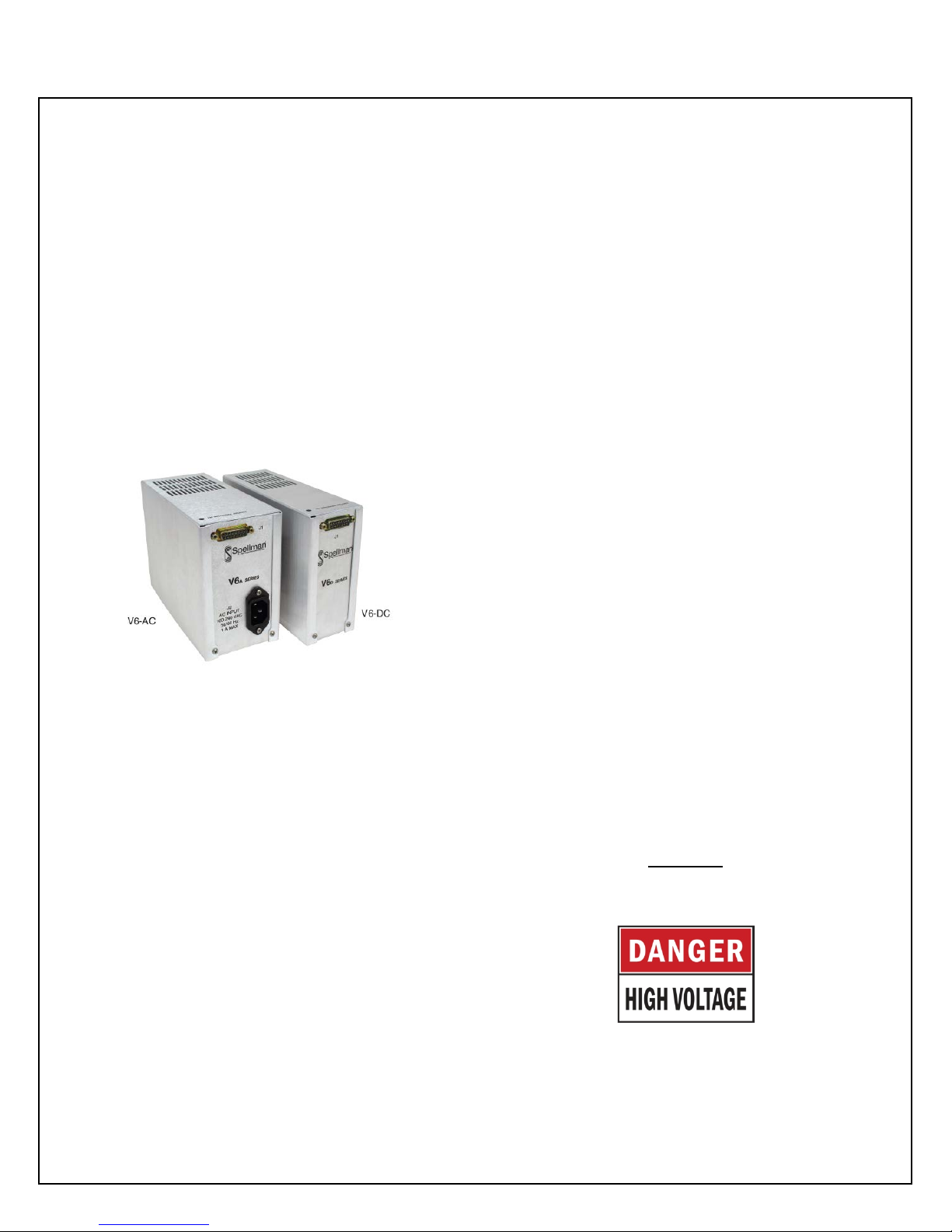
1.1 Description of the V6 Series
Spellman’s V6 Series is a family of regulated, fixed
output polarity module high voltage power supplies which
provide exceptional performance and value in many
applications. Utilizing proprietary power conversion
technology these SMT based high voltage modules
provide improved performance, reliability and easy
system integr ation. T he V6 series units are fully enclosed
and designed for system or bench top operation.
The V6 is rated at 30 watts with output voltages spanning
from 1kV to 30kV with fixed positive or negative
polarities. Voltage & Current loo ps with automatic cross
over control regulate the output into any load condition.
The output voltage is controlled locally by an internal
multi-turn potentiometer. Remote analog voltage and
current programming capability are included in all
models. Analog monitor outputs are also included for
remote monito ring of outp ut voltage and current. The V6
is a reliable and robust series that is arc a nd short circuit
protected. The comprehensive standard interface provides
interfacing flexibility and all V6 units are CE, UL and
RoHS compliant.
1.2 S t a nda rd Features
The V6 Series incorporates several standard features
designed to optimize user satisfaction and safety:
●Current Regulating Loop: Current programmability
allows the user to set where the unit will current limit,
anywhere from 0 to 100% of maximum rated current.
● 0 to +5Vdc Remote Programming Inputs: Positive
polarity, high impedance, ground referenced 0 to 5Vdc
voltage programming inputs correspond to 0 to 100%
rated voltage and current outputs.
● Local Control: Multi-turn potentiometer located on the
top of the unit is provided to control the output voltage
locally.
● 0 to +5Vdc Monitor Outputs: Positive polarity, low
impedance, ground referenced 0 to 5Vdc voltage monitor
outputs correspond to 0 to 100% rated output voltage and
current.
● Precision +5Vdc Reference Output: A precision
micro power band gap reference of +5Vdc, ±0.5%,
25ppm/°C is provided to simplify remote programming of
the power supply.
● Arc and Short Circuit Protected: Due to the fixed,
high frequency conversion rate the V6 series output
capacitance is small resulting in minimal stored energy.
Through the use of generously rated surge limiting
resistors and a fast acting c urrent loop, all units are fully
arc and short circuit protected.
1.3 Re m ot e Ope rating Features
● Enable Input: The Enable Input allows the user to
easily control the HV ON/OFF status o f t he power supply.
HCMOS compatible signals A low (<1.5Vdc) enable
input signal e quals HV ON, w hil e a high (open or >3 V d c)
enable signal equals HV OFF.
Warning!
The Enable Input should not be used as
protection against user injury or for a safety
interlock function.
1.4 Option
RS232 interface is available
V6 Series MANUAL 1 118130-001 REV C
Page 9
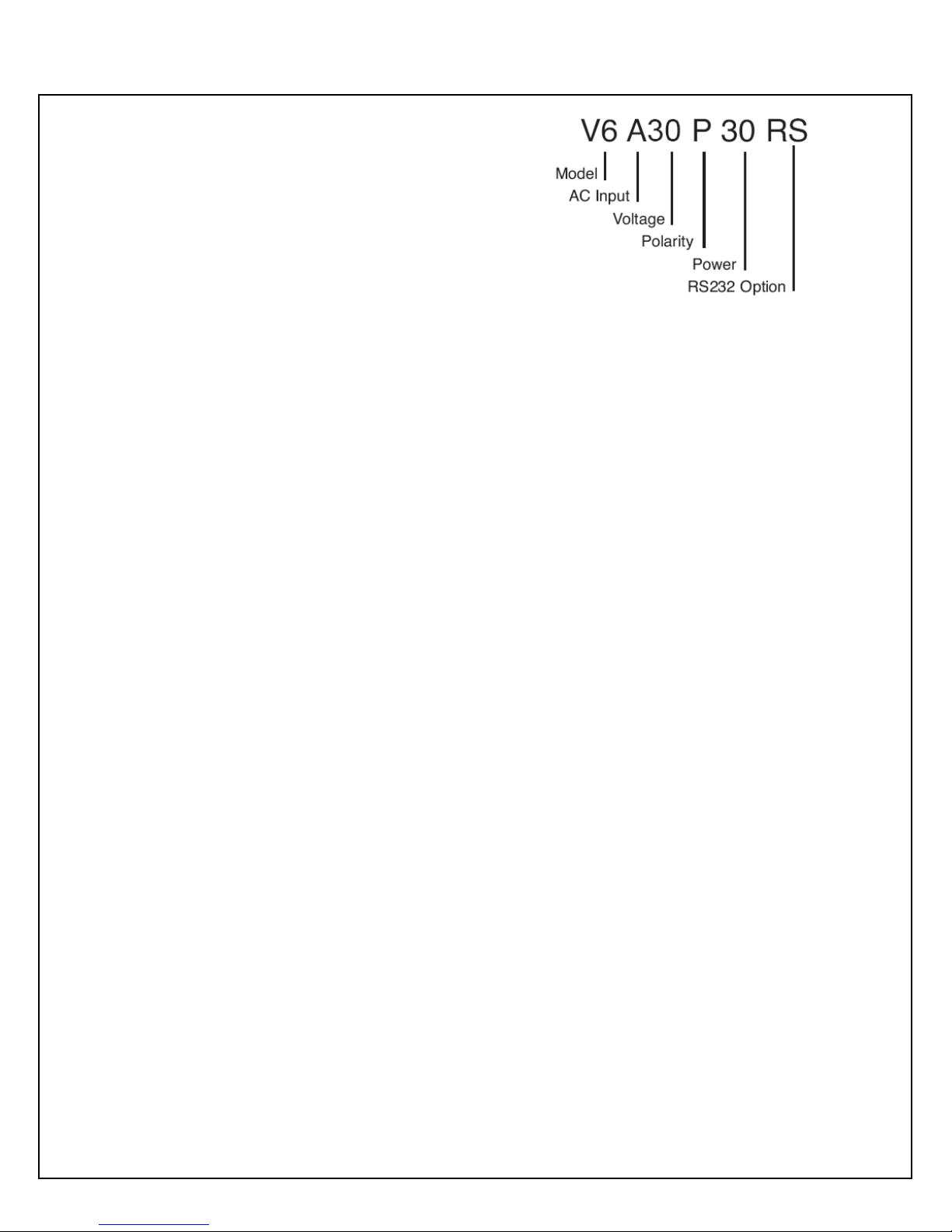
1.5 Interpreting the Model
Number
The power supplies model number describes its
capabilities. Model numbers are configured as follows:
U6A30P30RS where:
V6 is the product series name
A is for AC input voltage and D for DC input voltage
30 is the maximum output voltage in kV
P is the output polarity
30 is the output power in watts
RS is for RS-232 interface (omit RS for analog interface)
Interface
X numbered units are unique units custom developed for
specific application requirements above and beyond the
scope of the available standard options. Each 4 digit X
number corresponds to an applicable specification control
drawing.
V6 Series MANUAL 2 118130-001 REV C
Page 10

Chapter 2
INSPECTION & INSTALLATION
Initial inspection and preliminary checkout procedures are
recommended. For safe operation, please follow the
procedures described in Chapter 3, Operating Instructions.
2.1 Initial In spection
Inspect the packaging exterior for evidence of damage
due to improper handling in tr ansit. Notify the car rier and
Spellman High Voltage immediatel y if damage is evident.
Do not destroy or remove any of the packing material
used in a da maged shipme nt.
After unpacking inspect the power supply for any visible
signs of damage.
2.2 Mechanical Installation
V6 units ca n be mounted in any position using the tapped
holes in the base plate. 8-32 screws are required for
mounting. Please see the V6 series data s heet for a more
detailed dimensional drawing.
2.3 Temperature Consideration
It is the user’s responsibility to maintain the case
temperature below 50°C. Damage to the power supply
due to inadequate cooling is considered misuse and
repairs will not be covered under warranty
.
V6 Series MANUAL 3 118130-001 REV C
Page 11
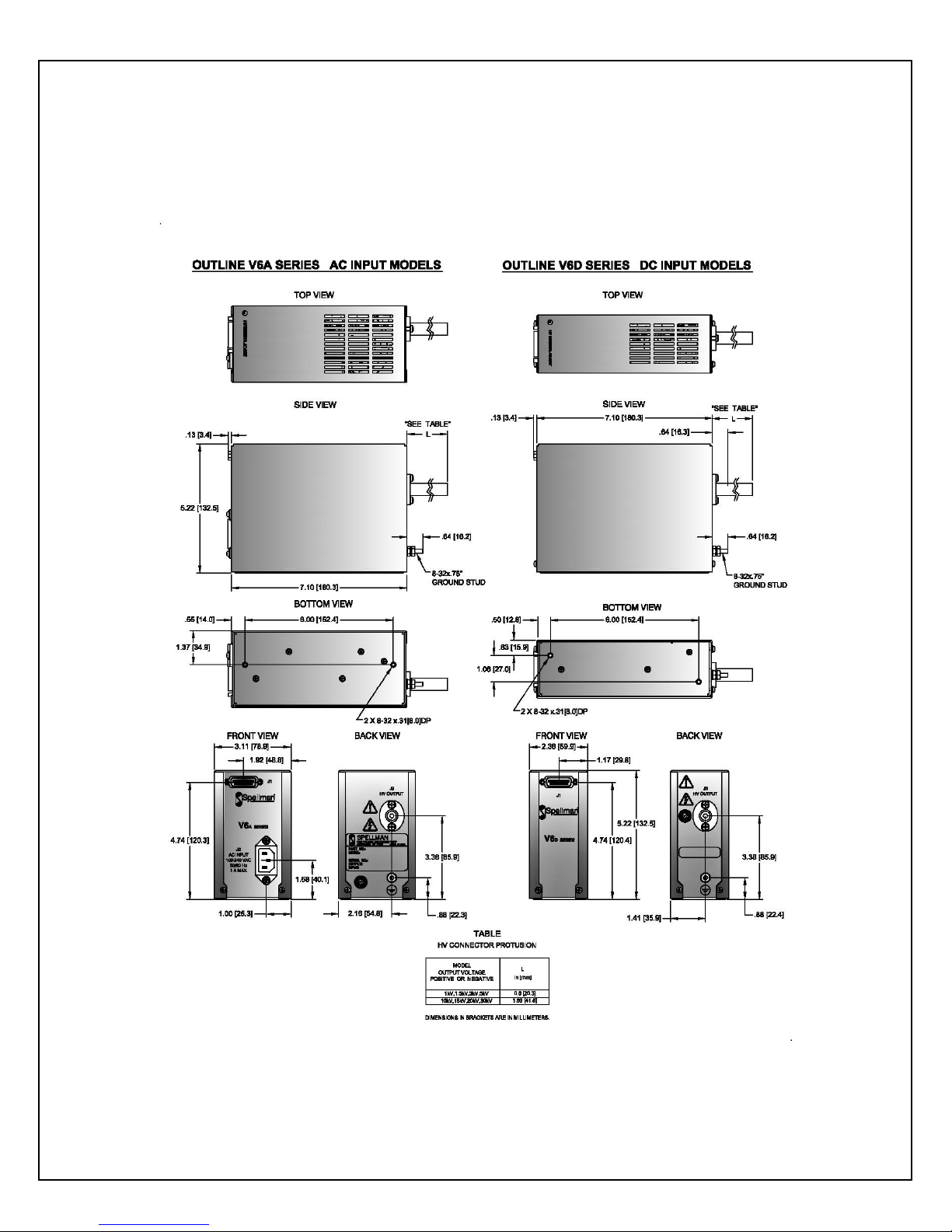
.
Figure 1 Outline Dimensions
V6 Series MANUAL 4 118130-001 REV C
Page 12
Chapter 3
Operating In structions
3.1 Operation
WARNING!
This equipment generates dangerous voltages
that may be fatal.
Proper grounding of all high voltage equi p ment
is essential.
It is highly recommended that all testing comply
with IEEE Standard 510-1983 IEEE
Recommended Practices for Safety in High
Voltage and High Power Testing. A copy of this
standard can be downloaded from the Spell m an
High Voltage website
INPUT VOLTAGE
Check the identification label on the power supply and
confirm it matches the input voltage of the so urce suppl y
that will be used to power the V6 module. T he DC units
operate with +24Vdc ± 10%, 2Amp. The AC units
operate from 90Vac to 264Vac 50/60 Herts, 1Amp
HIGH VOLTAGE CONNECTION
Insure that high voltage connection is properly terminated
to the load. Co nfirm that adequate air isolatio ns spacings
exist for the maximum voltage of the power supply, using
the guideline of 10kV per inch (25.4mm) to any points
that will be elevated to high voltage. All acce ssible high
voltage points should be enclosed in a protective Faraday
enclosure. Any access panels on the safety enclosure
should be interlocked.
V6 Series MANUAL 5 118130-001 REV C
here.
GROUNDING
Proper grounding of the unit is essential for reliable
operation. Power Ground, Signal Ground and HV Ground
Return are connected internally.
The Power Ground connection (J1 Pin 13) carries the
+24Vdc current that powers the unit. Make this
connection adequate enough to handle 2 amps, minimum.
Additionally it is recommended that this connection be
used to tie the power supply to whatever potential is used
as the local “system ground”.
Signal grounds relating to programming and monitor
functions should be referenced to the V6’s Signal Ground
(J1 Pin 6).
A physical load return connection must be made from the
bottom of the load to the power supplies HV Ground stud
(chassis).
See Figure 2 for DC modules details.
See Figure 3 for AC modules details.
OPTIONS
See Section 5 of this manual for RS-232 Communication
Protocol. Custom X numbers units may also require
special test requirements; con sult the unit’s specification
control drawing for details.
SIGNAL CONNECTIONS
Connect the appropriate programming and monitoring
signals to the unit as detailed in the figures in this chapter.
INITIAL TURN ON
A) Set t he voltage and current p rogramming inputs
for zero output (J1-4 and J1-9 respectively).
Open t he Enable Input (J1-8), to a ssure the unit
is in HV OFF mode.
B) The DC or AC input power can now be
connected.
C) Enable the power supply by grounding the
Enable Input (J1-8).
Page 13

D) Set the cur rent programming level (J1-9) to just
above the current anticipated that will be drawn
from the power supply.
E) Slo wly increase the voltage p rogramming (J1-4)
while monitoring the voltage and current
monitors (J1-10 and J1-11 respectively).
Carefully note proper equipment operation and
that the load is behaving as predicted.
F) To turn the H V OFF , open th e Enable Input ( J1-
8). If the equipment is to be left off for an
extended period of time or service of the unit or
load is required, turn off the input power.
WARNING!
After turn
been connected to the output of the power
supply. Wait a minimum of 5 minutes, and then
discharge any remaining stored energy by
connecting the high voltage output to ground.
Failure to follow these safety warnings can result
off, do not touch anything that has
in injury or death.
3.2 S t a nda rd Features
Programming and monitoring of the V6 Series is
accomplished via the use of conventional positive
polarity, gro und referenced signals. All signa l inputs and
outputs are noise filtered, impedance protected and diode
clamped providing an easy to use, robust analog customer
interface. Excellent results have been obtained via the use
of standard engineering design guidelines like twisted
pair, shielded cables, the prudent dressing of interface
wiring away from possible noise sources, short cable runs
and adhering to a well thought out and executed
grounding topology.
REMOTE PROGRAMMING
The V6’s programming and monitor signals are based
upon a universal, positive polarity, ground referenced
signal such that 0 to 5Vdc corresponds to 0 to 100% rated
output.
Programming can be accomplished via the use of an
applicable customer provided ground referenced voltage
source that meets the mentioned requirements. See Figure
4 for details.
If such a source is not available a precision +5Vdc
reference is provided on J1-7. A simple adjustable voltage
divider can be created using this reference and an external
potentiometer(s) which will provide full control of the
voltage and current loops.
See Figure 5 for details.
LOCAL PROGRAMMING
Local programming can be accomplished via the use the
multi turn potentiometer on the top of the unit.
Continuous multi-turn precision potentiometers directly
dial the output voltage . T he re so lutio n o f the pot is 0.05%
of maximum. The potentiometers are screwdriver
adjustable and easily accessed. For local voltage control
the following pins must be shorted: J1-1 to J1-5, J1-7 to
J1-9. See Figure 6 for details.
REMOTE MONITORING
The voltage and current monitor signals have adequate
bandwidth capability to accurately represent the actual
respective output within t he dynamic limits o f the power
supply. See Figure 7 for details.
ENABLE INPUT
The enable input signal provides simple control of the
ON/OFF functionality of the high voltage output. See
Figure 8 for deta ils.
WARNING!
It is extremely dangerous to use this cir cuit to
inhibit high voltage generation for the purpose of
servicing or approaching any area considered
unsafe during normal usage.
V6 Series MANUAL 6 118130-001 REV C
Page 14

V6D Unit
High Voltage Connection
Load Return Connection
System Ground
Customer
Load
HV
Out
GND
Stud
J1-13
Power Ground Return
Power Input
J1-15
J1-6
Signal Ground
V6A Unit
High Voltage Connection
Load Return Connection
System Ground
Customer
Load
HV
Out
GND
Stud
J2-L
J2-G
J2-N
Line
Ground
J1-6
Signal Ground
Neutral
AC Input
Power
V6 Unit
High Voltage Connection
Load Return Connection
System Ground
Customer
Load
HV
Out
GND
Stud
J1-9
I Program
V Program
J1-6
Signal Ground
DC
+
DC
+
-
J1-4
V6 Unit
High Voltage Connection
Load Return Connection
System Ground
Customer
Load
HV
Out
GND
Stud
J1-7
+5V REF
I Pgm
J1-9
J1-6
Signal Ground
J1-4
V Pgm
I Pgm
10KΩ
10KΩ
Figure 2
Grounding DC Unit
Figure 3
Grounding AC Unit
Figure 4
Remote Programming with a Remote Voltage Source
Vprg / Iprg: 0 to 5Vdc = 0 to 100% Rated Output
If one pot is not used connect the other programing input directly to +5V Reference J1-7
V6 Series MANUAL 7 118130-001 REV C
Figure 5
Programming using the +5V Reference
Page 15

Figure 6
V6 Unit
High Voltage Connection
Load Return Connection
System Ground
Customer
Load
HV
Out
GND
Stud
J1-1
Local Voltage Program
Voltage Program Input
J1-4
J1-9
Current Program Input
J1-7
+5V Reference Out
V6 Unit
High Volt age Con nection
Load Return Connection
Sy s te m Gro un d
Cust o mer
Load
HV
Out
GND
St ud
J1-10
Imon
Vm on
J1-6
Signal Ground
Meter
J1-11
Meter
V6 Unit
High Voltage Connection
Load Return Connection
System Ground
Customer
Load
HV
Out
GND
Stud
J1-8
Enable Input
J1-6
Signal Ground
HV OFF – High (>3Vdc)
or switch open
HV ON – Low (<1.5Vdc)
or switch closed
Local Programming using the internal multi turns potentiometer
Figure 7
Remote Voltage and Current Monitoring
Vmon / Imon: 0 to 5Vdc = 0 to 100% Rated Output
Figure 8
Enable Input
V6 Series MANUAL 8 118130-001 REV C
Page 16

Chapter 4
Principles of Ope ration
Warning!
The energy levels used and generated by the
power supply can be lethal! Do not attempt to
operate the power supply unless the user has
sufficient knowledge of the dangers and hazards
of working with high voltage. Do not attempt to
approach or touch any circuits that are
connected to or have been connected to the
power supply. Be certain to discharge any stored
energy that may be present before and after the
power supply is used. Consult IEEE
recommended practices for safety in high
voltage testing document number 510-1983.
4.1 DC/AC Input
The V6 Series is a DC to DC converter. Within the power
supply conve rsions fro m low voltage DC, to low voltage
AC, to high voltage AC and finally to high voltage DC
takes place. The DC input +24Vdc powers the power
conversion circuitry that creates the high voltage output
along with the low voltage DC housekeeping vo l tages that
provide power to the affiliated support control circuitry.
The AC units use an off the shelf universal input 24V
switching power supply.
4.2 Inverter
The DC input voltage is fed to the Inverter circuitry. Here
the low voltage DC is converted to a low voltage, high
frequency AC signal. T his power conversion step allows
for all subs equent power processing to take advanta ge of
component miniaturization due to the high operational
frequency. T he Inverte r functi onality is c ontrolled via the
power supply’s regulating loops which allows for
complete command of the desired output voltage and
current.
4.3 High Voltage Transformer
The high voltage transformer is a ferrite core step up type
in which the primary is driven from the output of the
Inverter circuit. The secondary of the high voltage
transformer feeds the High Voltage Output Section.
4.4 High Voltage Output Section
The High Voltage O utput Section utilizes an arrangement
of half wave Cockcroft-Walton voltage multiplier stages
to obtain the necessary output voltage.
The actual output voltage is sampled via a high
impedance divider to create a voltage feedback signal. A
current feedback signal is created via a current sense
resistor in t he low end return of the Hig h Voltage O utput
Circuitry. These two accurate ground referenced feedback
signals are used to precisely regulate and control the unit,
in addition to providing external monitoring.
4.5 Cont rol Circuitry
Various SMT based control circuitry is used for all
interfacing, monitoring and re gulation functionalit y of the
V6 modular power supply.
The voltage and current feedback signals generated in the
High Voltage Output Section are compared to the
requested voltage and current commands from the remote
interface. The voltage or current loop error amplifier
creates the appropriate error signal which is then provided
to the Pulse Width Modulation (P WM) circuitry.
The output of the PWM circuitry drives the Inverter
circuit to provide the required output in a continuous
closed loop control process, regulating in either voltage
mode or current mode as required.
V6 Series MANUAL 9 118130-001 REV C
Page 17

The internally generated voltage and current feedback
signals are processed and provided to the remote interface
for monitoring purposes.
The Enable Input from the remote interface controls the
HV ON and HV OFF status of the power supply by
interfacing with the PWM circuitry.
A precision +5Vdc, ±0.5%, 25ppm/°C micro power band
gap reference output is provided for user programming
convenience .
Figure 9 - Block Diagram
V6 Series MANUAL 10 118130-001 REV C
Page 18

Chapter 5
PIN
SIGNAL PARAMETERS
1
Not Used
2
RS232 Receive Data
3
RS232 Transmit Data
4
Not Used
5
RS232 Ground
6
Ground
7
Not Used
8
Not Used
9
Not Used
10
0 to 5V=0 to 100% Rated Output, Zout=10kΩ (Analog)
11
0 to 5V=0 to 100% Rated Output, Zout=10kΩ (Analog)
12
Not Used
13
Input Voltage Return used for DC
14
Input Voltage 24V ±10%, 2A used for DC
15
Input Voltage 24V ±10%, 2A used for DC
OPTION
5.1 RS-232 Interface
See attached document 118109-001
for Communication Protocol
RS-232 interface options, see table below
V6 AC/DC Analog/Digital Interface J1 15 pin D-connector Table
V6 Series MANUAL 11 118130-001 REV C
Page 19

Chapter 6
MAINTENANCE
WARNING!
This power supply generates voltages tha t
are dangerous and may be fatal.
Observe extreme caution when working with
high voltage.
6.1 Periodic Servicing
The V6 product family does not require any periodic
maintenance or servicing.
6.2 Per f ormance Testing
WARNING!
High Voltage is dangerous.
Only qualified personnel should perform
these tests.
It is highly recommended that all testing
comply with IEEE Standard 510-1983 IEEE
Recommended Practices for Safety in High
Voltage and High Power Testing. A copy of
this standard can be downloaded from the
Spellman High Voltage website
here.
Test equipment includes, but is not limited to: an
oscilloscope, a high impedance digital volt meter, a
current meter, a ripple checker, a high voltage load, a
high voltage d ivider (such as the Sp ellman H VD-100
or HVD-200) an insulated load stick and insulated
short circuit stick and a safety interlocked Faraday
test cage to safety conduct the tests inside of. All
equipment must be properly rated for the power
supply to be tested. If you do not possess the required
equipment and skills necessary to safety conduct
these tests do not attempt to perform these
performance tests.
6.3 High Voltage Dividers
High voltage dividers for precise measurements of
output voltage with accuracy up to 0.1% are available
from Spellman. The HVD-100 is used for voltages up
to 100KV, the HVD-200 measures up to 200KV.
The HVD Series of high voltage dividers are
designed for use with differential volt meters or high
impedance digital voltmeters. The high input
impedance of the HVD Series is ideal for measuring
high voltage low current sources, which would be
overloaded by traditional lower impedance dividers.
Generalized high voltage test procedures are
described in Bulletin STP-783, Standard Test
Procedures for High Voltage Power Supplies.
A copy of this bulletin can be downloaded from the
Spellman High Voltage website here
V6 Series MANUAL 12 118130-001 REV C
The HVD Series data sheet can be downloaded from
the Spellman High Voltage website here
Spellman Sales Department for information on price
and availability.
.
HVD Dividers
. Contact the
Page 20

Chapter 7
FACTORY SERVICE
7.1 Warranty Repairs
During the Warranty period, Spell man will repair all units
free of charge. The Warranty is void if the unit is worked
on by anyone other than Spellman personnel. See the
Warranty in the rear of this manual for more information.
Follow the return procedures described in Section 7.2.
The customer shall pay for shipping to and from
Spellman.
7.2 Factory Service Procedures
Spellman has a well-equipped factory repair department.
If a unit is returned to the factory for calibration or repair,
a detailed description of the specific problem should be
attached.
For all units returned for repair, please obtain an
authorization to ship from the Customer Service
Department, either by phone or mail prior to shipping.
When you call, please state the model and serial numbers,
which are on the plate on the rear of the power supply,
and the purchase order number for the repair. A Return
Material Authorization Code Number (RMA Number) is
needed for all returns. This RMA Number should be
marked clearly on the outside of the shipping container.
Packages received without an RMA Number will be
returned to the customer. The Customer shall pay for
shipping to and from Spellman.
7.3 Shipping Instructions
All power supplies returned to Spellman must be sent
shipping prepaid. Pack the units carefully and securely in
a suitable container, preferably in the original container, if
available. The power supply should be surrounded by at
least four inches of shock absorbing material. Please
return all associated materials, i.e. high voltage output
cables, interconnection cables, etc., so that we can
examine and test the entire system.
All correspondence and phone calls should be directed to:
Spellman High Voltage Electronics Corp.
One Commerce Park
Valhalla, New York 10595
TEL: (914) 686-3600
FAX: (914) 686-5424
E-Mail: sales@Spellmanhv.com
A preliminary estimate for repairs will be given by phone
by Customer Service. A purchase order for this amount is
requested upon issuance of the RMA Number. A more
detailed estimate will be made when the power supply is
received at the Spellman Repai r Center. In the eve nt that
repair work is extensive, Spellman will call to seek
additional authorization from your company before
completing the repairs.
V6 Series MANUAL 13 118130-001 REV C
Page 21

To obtain information on Spellman’s product warranty please visit our website at:
http://www.spellmanhv.com/en/About/Warranty.aspx
Page 22

V6 Series Power Supply Communication
Protocol
Serial – RS-232
Copyright 2011, Spellman High Voltage Electronics Corporation. All Rights Reserved.
This information contained in this publication is derived in part from proprietary and patent data. This information has
been prepared for the express purpose of assisting operating and maintenance personnel in the efficient use of the
model described herein, and publication of this information does not convey any right to reproduce it or to use it for
any purpose other than in connection with installation, operation, and maintenance of the equipment described.
DOC. 118109-001 REV B
475 Wireless Boulevard • Hauppauge, New York 11788, USA • www.spellmanhv.com • T:+1 631.630.3000 • F:+1 631.435.1620
Page 23

Table Of Contents
1.0 SCOPE ............................................................................................................................... 3
2.0 FUNCTIONAL DESCRIPTION ..................................................................................... 3
3.0 GETTING STARTED – HARDWARE SETUP ............................................................ 3
3.1 RS232 INTERFACE ...................................................................................................... 3
3.2 RS-232 CABLING ......................................................................................................... 3
4.0 GETTING STARTED – SOFTWARE ........................................................................... 4
4.1 RS-232 ............................................................................................................................ 4
5.0- SERIAL INTERFACE PROTOCOL ............................................................................. 4
5.1 COMMAND ARGUMENTS ......................................................................................... 5
5.2 CHECKSUMS ................................................................................................................ 5
5.3 COMMAND OVERVIEW ............................................................................................ 8
5.4 RESPONSE OVERVIEW .............................................................................................. 8
5.5 COMMAND STRUCTURE .......................................................................................... 9
5.5.1 Program KV ................................................................................................................... 9
5.5.2 Program Output Current ............................................................................................... 10
5.5.3 Request ADC Data ....................................................................................................... 11
5.5.4 Request Status .............................................................................................................. 12
5.5.5 Request Software Version ........................................................................................... 13
5.5.6 Request Hardware Version ........................................................................................... 14
5.5.7 Request Model Number ................................................................................................ 15
5.5.8 Set H.V. OffOn ............................................................................................................. 16
Standard V6 Series Communication Protocol 2 118109-001 REV B
Page 24

1.0 SCOPE
This document applies to the communication interface on the V6 Series Power
Supply.
2.0 FUNCTIONAL DESCRIPTION
The V6 Series power supply provides a serial communications interface:
RS-232 on J1 I/O Connector
.
Data acquisition and control capabilities are provided by:
14 channels of 12-bit analog-to-digital converters
2 additional analog channels that monitor the house-keeping power supply
and ambient temperature
5 digital output bits
8 digital inputs bits
3 relays/interlocks
3.0 GETTING STARTED – HARDWARE SETUP
The digital hardware includes a 40MIPS digital signal processor
processor/controller
3.1 RS232 INTERFACE
The RS232C interface has the following attributes:
115.2K bits per second
No Parity
8 Data Bits
1 Stop Bit
No handshaking
3.2 RS-232 CABLING
An RS-232 cable where one end is a DB9 connector and the other end is
a DB15 male connector. Line 2 is connected straight through to pin 2 and
3 line is conncected straight through to line 3. Please refer to the following
chart.
Standard V6 Series Communication Protocol 3 118109-001 REV B
Page 25

PC Connector (DB-9 Female)
PC to SIC Board Cable Details
Pin 2: RX In Pin 2: RX Out
Pin 3: TX Out Pin 3: TX In
Pin 5: Ground Pin 5: Ground
4.0 GETTING STARTED – SOFTWARE
The following sections detail how to create software to interface to the V6 Series
communications interfaces.
4.1 RS-232
The RS-232 interface makes use of a standard ‘command/response’
communications protocol. See section 6.0 for the syntax of the serial
interface protocol.
All software that addresses the RS-232 interface must adhere to the
following parameters:
115K.2 bits per second
No Parity
8 Data Bits
1 Stop Bit
No handshaking
5.0- SERIAL INTERFACE PROTOCOL
J1 Connector (DB-15
Female)
Serial communications will use the following protocol:
<STX><CMD><,>ARG><,><CSUM><ETX>
Where:
<STX> = 1 ASCII 0x02 Start of Text character
<CMD> = 2 ASCII characters representing the command ID
<,> = 1 ASCII 0x2C character
Standard V6 Series Communication Protocol 4 118109-001 REV B
Page 26

<ARG> = Command Argument
<,> = 1 ASCII 0x2C character
<CSUM> = Checksum (see section 5.2 for details)
<ETX> = 1 ASCII 0x03 End of Text character
5.1 COMMAND ARGUMENTS
The format of the numbers is a variable length string. To represent the number
42, the string ‘42’, ‘042’, or ‘0042’ can be used. This being the case, commands
and responses that carry data are variable in length.
5.2 CHECKSUMS
The checksum is computed as follows:
Add the <CMD>, <,>, and <ARG>, and <,> bytes into a 16 bit (or larger)
word. The bytes are added as unsigned integers.
Take the 2’s compliment (negate it).
Truncate the result down to the eight least significant bits.
Clear the most significant bit (bit 7) of the resultant byte, (bitwise AND with
0x7F).
Set the next most significant bit (bit 6) of the resultant byte (bitwise OR
with 0x40).
Using this method, the checksum is always a number between 0x40 and 0x7F.
The checksum can never be confused with the <STX> or <ETX> control
characters, since these have non-overlapping ASCII values.
If the DSP detects a checksum error, the received message is ignored – no
acknowledge or data is sent back to the host. A timeout will act as an implied
NACK.
Standard V6 Series Communication Protocol 5 118109-001 REV B
Page 27

The following is sample code, written in Visual Basic, for the generation of
checksums:
Public Function ProcessOutputString(outputString As String) As String
Dim i As Integer
Dim CSb1 As Integer
Dim CSb2 As Integer
Dim CSb3 As Integer
Dim CSb$
Dim X
X = 0
For i = 1 To (Len(outputString)) 'Starting with the CMD character
X = X + Asc(Mid(outputString, i, 1)) 'adds ascii values together
Next i
CSb1 = 256 - X 'Twos Complement
CSb2 = 63 And (CSb1)
CSb3 = 64 Or (CSb2) 'OR 0x40
CSb$ = Chr(Val("&H" & (Hex(CSb3))))
ProcessOutputString = Chr(2) & outputString & CSb$ & Chr(3)
End Function
Here is an example of an actual Checksum calculation for command 10
(Program kV setpoint)
The original message with a placeholder for the checksum is
<STX>10,4095,<CSUM><ETX>
First, you add up all the characters starting with the ‘1’ in the command
number, to the comma before the checksum with their ASCII values (in
hexadecimal):
0x31 + 0x30 + 0x2C + 0x34 + 0x30 + 0x39 + 0x35 + 0x2C = 0x18B
Next, you then take the two’s complement of that number by negating it,
by subtracting it from 0x100 (decimal 256), and only retain the lowest 7
bits by bitwise ANDing the results with 0x7F. :
NOTE: This combines the steps of getting the twos complement,
truncating the result to 8 bits and clearing the 8th bit.
Standard V6 Series Communication Protocol 6 118109-001 REV B
Page 28

(0x100 – 0x18B) & 0x7F = 0x75
Finally, bitwise OR the result with 0x40:
0x75 | 0x40 = 0x75
The checksum byte is 0x75 (Decimal 117, ASCII: u)
Here is another example, this time for command 22 (Request Status) which has
no arguments.
The original message with a placeholder for checksum is:
<STX>22,<CSUM><ETX>
First, you add up all the characters starting with the ‘2’ in the command
number to the comma before the checksum with their ASCII values (in
hexadecimal):
0x32 + 0x32 + 0x2C = 0x90
Next, you then take the two’s complement of that number by negating it,
by subtracting it from 0x100 (decimal 256), and only retain the lowest 7
bits by bitwise ANDing the results with 0x7F:
NOTE: This combines the steps of getting the twos complement,
truncating the result to 8 bits and clearing the 8th bit.
(0x100 – 0x90) & 0x7F = 0x70
Finally, bitwise OR the result with 0x40:
0x70 | 0x40 = 0x70
The checksum byte is 0x70 (Decimal 112, ASCII: p)
Standard V6 Series Communication Protocol 7 118109-001 REV B
Page 29

5.3 COMMAND OVERVIEW
Command Name <CMD> <ARG> RANGE
Program KV (DAC
10 1-4 ASCII 0-4095
A)
Program Output
11 1-4 ASCII 0-4095
Current (DAC B)
Request ADC Data 20 None Request Status 22 None Request Software
23 None Version
Request Hardware
24 None Version
Request Model
26 None Number
Set H.V. OnOff 99 1 or 0 -
5.4 RESPONSE OVERVIEW
The command responses will follow the same format as outlined above in
section 5.3. This list is comprised of Commands with complex responses
only. Commands using a simple response will use the <$> character
(ASCII 0x24) as a “Success” response or a single character error code.
These responses will be eight ASCII characters in length.
Response Name <CMD> Response
Request Analog
Readbacks – KV &
20 20-41
ASCII
MA
Request Status 22 12 ASCII
Request DSP
23 18 ASCII
Software Version
Request Hardware
24 10 ASCII
Version
Request Model
26 12 ASCII
number
Standard V6 Series Communication Protocol 8 118109-001 REV B
Page 30

5.5 COMMAND STRUCTURE
5.5.1 Program KV
Description:
The host requests that the firmware change the setpoint of DAC
Channel A.
Direction:
Host to supply
Syntax:
<STX><10><,><ARG><,><CSUM><ETX>
Where:
<ARG> = 0 - 4095 in ASCII format
Example:
<STX>10,4095,<CSUM><ETX>
Detailed Example:
02 31 30 2C 34 30 39 35 2C 75 03
Response:
<STX><10><,><$><,><CSUM><ETX>
Standard V6 Series Communication Protocol 9 118109-001 REV B
Page 31

5.5.2 Program Output Current
Description:
The host requests that the firmware change the setpoint of DAC Channel
B.
Direction:
Host to supply
Syntax:
<STX><11><,><ARG><,><CSUM><ETX>
Where:
<ARG> = 0 - 4095 in ASCII format
Example:
<STX>11,4095,<CSUM><ETX>
Response:
<STX><11><,><$><,><CSUM><ETX>
Standard V6 Series Communication Protocol 10 118109-001 REV B
Page 32

5.5.3 Request ADC Data
Description:
The host requests that the firmware report the current ADC Channel KV
monitor, and Channel MA monitor.
Direction:
Host to supply
Syntax:
<STX><20><,><CSUM><ETX>
Response:
<STX><20><,><ARG1><,><ARG2><,><CSUM><ETX>
Where:
<ARG1> KV: 0 - 4095 in ASCII format
<ARG2> MA: 0 - 4095 in ASCII format
Example:
<STX>20,4095,4095,<CSUM><ETX>
Standard V6 Series Communication Protocol 11 118109-001 REV B
Page 33

5.5.4 Request Status
Description:
The host requests that the firmware report the current DAC Channel D
setpoint.
Direction:
Host to supply
Syntax:
<STX><22><,><CSUM><ETX>
Response:
<STX><22><,><ARG1><,><ARG2><,><ARG3><,><CSUM><ETX>
Where:
<ARG1> 1 = Over Voltage, 0 = Normal
<ARG2> 1 = Over Current, 0 = Normal
<ARG3> 1 = Enable, 0 = Disable
Example:
<STX>22,0,0,0,<CSUM><ETX>
Standard V6 Series Communication Protocol 12 118109-001 REV B
Page 34

5.5.5 Request Software Version
Description:
The host requests that the firmware sends the DSP firmware part
number/version.
Direction:
Host to supply
Syntax:
<STX><23><,><CSUM><ETX>
Example:
<STX>23,<CSUM><ETX>
Response:
<STX><23><,><ARG><,><CSUM><ETX>
Where:
<ARG> consists of eleven ASCII characters representing the current
firmware part number/version. The format is SWM9999-999
Example:
<STX>23,SWM9999-999,<CSUM><ETX>
Standard V6 Series Communication Protocol 13 118109-001 REV B
Page 35

5.5.6 Request Hardware Version
Description:
The host requests that the firmware sends the hardware version.
Direction:
Host to supply
Syntax:
<STX><24><,><CSUM><ETX>
Example:
<STX>24,<CSUM><ETX>
Response:
<STX><24><,>< ARG><,><CSUM><ETX>
Where:
<ARG> consists of 3 ASCII characters representing the hardware version.
The format is ANN, where A is an alpha character and N is a numeric
character
Example:
<STX>24,A01,<CSUM><ETX>
Standard V6 Series Communication Protocol 14 118109-001 REV B
Page 36

5.5.7 Request Model Number
Description:
The host requests that the firmware sends the unit model number
Direction:
Host to supply
Syntax:
<STX><26><,><CSUM><ETX>
Example:
<STX>26,<CSUM><ETX>
Response:
<STX><26><,><ARG><,><CSUM><ETX>
Where:
<ARG> consists of five ASCII characters representing the model number.
The format is XNNNN, where N is a numeric character.
Example:
<STX>26,X9999,<CSUM><ETX>
Standard V6 Series Communication Protocol 15 118109-001 REV B
Page 37

5.5.8 Set H.V. OffOn
Description:
The host requests that the firmware set H.V. Off or On
Direction:
Host to supply
Syntax:
<STX><99><,><ARG><,><CSUM><ETX>
Where:
<ARG> = 0 = HV Off, 1 = HV On.
Example:
<STX>10,1,<CSUM><ETX>
Response:
<STX><10><,><$><,><CSUM><ETX>
Standard V6 Series Communication Protocol 16 118109-001 REV B
 Loading...