

Page 1
R
Instruction Manual
uX SERIES
MODEL :
SERIAL# :
DATE :
SPELLMAN
HIGH VOLTAGE ELECTRONICS
CORPORATION
475 Wireless Blvd.
Hauppauge, New York, 11788
+1(631) 630-3000*FAX: +1(631) 435-1620*
E-mail: sales@spellmanhv.com
Website: www.spellmanhv.com
High Voltage Power Supply
uX MANUAL 118152-001 Rev A
Page 2

The uX Series is the result of Spellman’s exceptional
high voltage packaging and surface mount fabrication
techniques coupled with proprietary encapsulation
technology producing this ultra-compact X-Ray generator
module. The uX powers grounded cathode X-Ray tubes
from a variety of well-known manufacturers, featuring a
0 to 50kV/65kV high voltage output @ 2mA limited to 50,
65 or 75 Watts. The uX uses closed loop filament control
circuitry providing highly regulated beam current. The low
noise dc filament supply operates between 0.3 and 3.5
amps. Offering tight regulation, high stability and low
ripple, the uX provides users local and remote analog
control to set beam voltage, emission current and filament
current limit. USB, RS-232 and Ethernet interface is standard.
TYPICAL APPLICATIONS
Powering grounded cathode X-Ray tubes from
Kevex, Oxford, RTW, Superior, Varian and Trufocus.
OPTIONS
XCC XRM Compatible HV Cable (50kV only)
5VPM 0 to 5 Volt Programming and Monitor Scaling
GB Grid Bias Option
K5302 Mammoflex HV cable for uX
K2001 Mammoflex HV cable for uX w/XCC option
SPECIFICATIONS
Input:
+24Vdc ±10%, 5.0A maximum for either 50 Watts or 75 Watts.
+24Vdc ±1V, 5.0A maximum for 65kV/65W units.
Efficiency:
75%, typical
Output:
0 to 50kV at 0 to 2mA, limited to a maximum of 50 wattsr
or 75 Watts. 0-65kV at 2mA limited to 65 Watts.
Voltage Control:
Local: Internal multi-turn potentiometer to set voltage
from 0 to full output voltage.
Remote: 0 to +10Vdc proportional from 0 to full output voltage.
Accuracy: ±1%. Z
IN
: 10Mohm.
Emission Control:
Local: Internal potentiometer to set beam current
between 0 and full output current.
Remote: 0 to +10Vdc proportional from 0 to full output current.
Accuracy: ±1%. Z
IN
: 10Mohm. Filament limit and
filament preheat control capability is also provided.
DC Filament Supply:
Islolated filament power supply generates emission
current feedback signal for accurate low X-Ray tube
current performance.
Current: 3.5A, adjustable limit
Voltage: 5.0 volt limit
Environmental:
Operational: 0°C to +50°C
Storage: -40°C to +85°C
Humidity: 0% to 90%, non-condensing
Temperature Coefficient:
0.01% per °C, voltage and current.
Stability:
0.05% per 8 hours after 1/2 hour warm-up.
Voltage and Current Monitors:
0 to +10Vdc proportional from 0 to rated output. Accuracy ±1%.
Redundant Voltage Monitor:
A redundant high voltage feedback divider with proportional
0 to +10Vdc = 0 to 100% output voltage signal can be provided
on a custom basis.
Dimensions:
50kV Unit: 4.00”H x 2.87”W x 8.00”D
(101.6mm x 72.95mm x 202.20mm).
65kV Unit: 4.00”H x 2.87”W x 9.00”D
(101.6mm x 72.95mm x 228.60mm).
XCC Option: 4.00”H x 2.87”W x 9.00”D
(101.6mm x 72.95mm x 228.60mm).
Weight:
4.5 lbs. (2.1kg) typical
Regulatory Approvals:
Compliant to 2004/108/EC, the EMC Directive and 2006/95/EC,
the Low Voltage Directive (approval pending). UL/CUL
recognized, File E227588 (approval pending). Compliant to
2002/95/EC, RoHS.
• 50kV at 2 mA. 50 or 75 Watt Max.
• 65kV at 2 mA. 65 Watt Max.
• Adjustable Isolated Filament Supply
• Overvoltage & Short Circuit Protection
• Voltage & Current Programming
• Local and Remote Emission Control
• Safety Interlock
• RS-232, Ethernet, & USB Standard
• Redundant HV Monitor Signal Available
• OEM Customization Available
SPELLMAN HIGH VOLTAGE ELECTRONICS CORPORATION
uX
50W/65W/75W X-RAY
GENERATOR
PAGE 1 OF 5
30% Smaller
than MNX
Corporate Headquarters
Hauppauge, New York USA
+1-631-630-3000 FAX: +1-631-435-1620
e-mail: sales@spellmanhv.com
www.spellmanhv.com
128108-001 REV. A
Spellman High Voltage is an ISO 9001:2008 and ISO 14001:2004 registered company
Copyright © 2014 Spellman High Voltage Electronics Corp.
Page 3
PAGE 2 OF 5
SPELLMAN HIGH VOLTAGE ELECTRONICS CORPORATION
uX
50W/65W/75W X-RAY
GENERATOR
Grid Bias Option (GB):
Plug-n-Play compatibility for Oxford’s Apogee X-Ray Tube
Spellman’s Grid Bias Option for the uX Series is specifically
designed for popular commercially available grid bias X-Ray
tubes. The Grid Bias voltage is developed via the use of separate integrated high frequency switching circuit, providing maximum flexibility and control. The Grid Bias output is a voltage
regulated, current compliant topology ideally suited for Wehnelt
electrode applications. Arc and short circuit protection of the
Grid Bias output prevents any damage due to transient events
or installation errors.
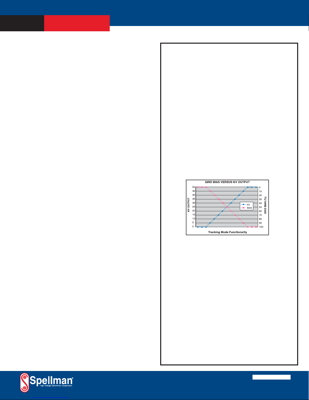
Tracking Mode Operation
Functioning in tracking mode the voltage monitor
(0-10Vdc = 0 to 50kV) of the main high voltage output
is internally connected to the Grid Bias programming input
(0-10Vdc = 0 to -300Vdc of Grid Bias). Connected in this
manner the Grid Bias output will track in a linearly
proportional fashion the setting of the main kV output.
A multiturn potentiometer limits the maximum magnitude
of Grid Bias output applied to the X-Ray tube, providing
unparalleled flexibility.
The output of the Grid Bias option is provided via an
auxiliary two position Phoenix Contact terminal block, the
mating connecter is provided.
GRID BIAS SPECIFICATIONS
Output Voltage: 0 to -300Vdc
Output Current: 0.25mA, maximum
Load Regulation: 1% of output voltage, no load to full load
Line Regulation: 1% for a ±10% change in input voltage
Ripple: 1% of maximum rated voltage
uX with Grid Bias Option.
Shown with Oxford Apogee X-Ray Tube
(not included)
Note: Units ordered with the
GB Option will be provided with the XCC Option
for proper high voltage cable compatibility.
Main Control Screen
Communication Screen
Filament Status Screen
Digital Interface
The uX features a standard USB, RS-232 and Ethernet digital
interface. Utilizing these standard digital interfaces can
dramatically simplify power supply interfacing requirements
saving the user both time and money, while enhancing functionality and overall capabiity. Spellman provides a GUI with
the uX that allows the customer to both customize operational
features of the uX while also providing basic power supply
operational features. Details of the uX’s digital interface
capability are described in detail in the uX manual.
Closeup showing digital
interface connectors
Corporate Headquarters
Hauppauge, New York USA
+1-631-630-3000 FAX: +1-631-435-1620
e-mail: sales@spellmanhv.com
www.spellmanhv.com
128108-001 REV. A
Spellman High Voltage is an ISO 9001:2008 and ISO 14001:2004 registered company
Copyright © 2014 Spellman High Voltage Electronics Corp.
Page 4
PAGE 3 OF 5
SPELLMAN HIGH VOLTAGE ELECTRONICS CORPORATION
uX
50W/65W/75W X-RAY
GENERATOR
ANALOG INTERFACE CONNECTOR
MALE 15 PIN MINI “D”
PIN SIGNAL PARAMETER
1 Monitor Return Signal Ground
2 Voltage Monitor 0-10 volts = 0 to full scale, Zout=1KΩ
3 Current Monitor 0-10 volts = 0 to full scale, Zout=1KΩ
4 Interlock Output Connect 12V HVON bulb to pin 15 to enable
5 +10 Volt Reference +10 Volts at 1mA, maximum
6 Filament Monitor 1 volt = 1 amp, Zout=1KΩ
7 Voltage Program Input 0-10 volts = 0 to full scale, Zin=10MΩ
8 Local Voltage Program* 0-10 volts, screwdriver adjust
9 Filament Limit Setpoint* 1 volt = 1 amp, screwdriver adjust
10 Current Program Input 0-10 volts = 0 to full scale, Zin=10MΩ
11 Local Current Program* 10 turn pot, screwdriver adjust
12 Not used (+24V Out for Interlock) (Optional Interlock configuration)
13 Not used (Interlock Coil) (Optional Interlock configuration)
14 Filament Preheat Setpoint* 1 volt = 1 amp, screwdriver adjust
15 Interlock Return Interlock Ground
POWER INPUT/FILAMENT CONNECTOR
4 PIN PHOENIX CONTACT
PIN SIGNAL PARAMETER
1 +24V Input +24 volts @ 5A, max.
2 24V Return (Gnd.) Power Ground
3 Filament Out 0.3A to 3.5A, 5 volt, max.
4 Filament Return Filament Return
HIGH VOLTAGE OUTPUT CONNECTOR
Spellman drywell type detachable connector.
Standard: A one meter (39.4”) long polyethylene mating high
voltage cable is provided.
K5302: A one meter (39.4”) long Mammoflex mating high voltage
cable is provided, SHV p/n 201946-007
K2001: A one meter (39.4”) long Mammoflex mating high voltage cable
is provided, compatible with the XCC Option SHV p/n 201946-002
GRID BIAS CONNECTOR
2 PIN PHOENIX CONTACT
PIN SIGNAL PARAMETER
1 Ground Chassis Ground
2 Grid Bias 0 to -300Vdc
How To Order:
Sample model number:
50 Watt unit: uX50P50
65 Watt unit: uX65P65
75 Watt unit: uX50P75
Options are added to the model number as follows:
uX50P50/XCC or uX50P75/GB
ETHERNET DIGITAL INTERFACE—
8 PIN RJ45 CONNECTOR
PIN SIGNAL SIGNAL PARAMETERS
1 TX+ Transmit Data +
2 TX- Transmit Data 3 RX+ Receive Data +
4 NC No Connection
5 NC No Connection
6 RX- Receive Data 7 NC No Connection
8 NC No Connection
RS-232 DIGITAL INTERFACE—
9 PIN FEMALE D CONNECTOR
PIN SIGNAL SIGNAL PARAMETERS
1 NC No Connection
2 TX out Transmit Data
3 RX in Receive Data
4 NC No Connection
5 SGND Ground
6 NC No Connection
7 NC No Connection
8 NC No Connection
9 NC No Connection
USB DIGITAL INTERFACE—
4 PIN USB “B” CONNECTOR
PIN SIGNAL SIGNAL PARAMETERS
1 VBUS +5 Vdc
2 D- Data 3
D+ Data +
4 GND Ground
*Denotes 10 turn potentiometer accessable through holes in cover
Corporate Headquarters
Hauppauge, New York USA
+1-631-630-3000 FAX: +1-631-435-1620
e-mail: sales@spellmanhv.com
www.spellmanhv.com
128108-001 REV. A
Spellman High Voltage is an ISO 9001:2008 and ISO 14001:2004 registered company
Copyright © 2014 Spellman High Voltage Electronics Corp.
Note: The filament return wire cannot be grounded as this would short
circuit the tube return current monitoring to the uX. If grounding of the
filament is required, please consult the factory.
Page 5
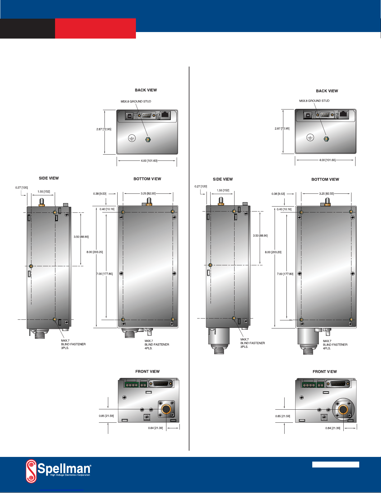
PAGE 4 OF 5
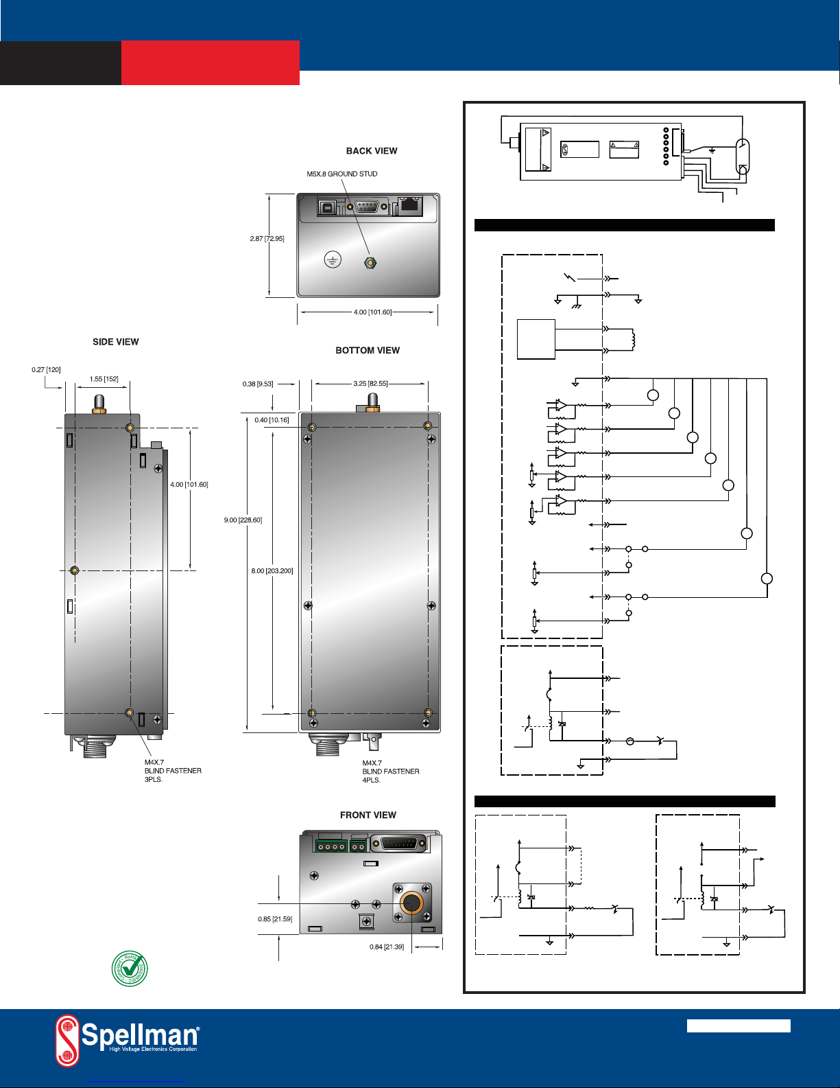
DIMENSIONS: in.[mm]
SPELLMAN HIGH VOLTAGE ELECTRONICS CORPORATION
uX
50W/65W/75W X-RAY
GENERATOR
50KV
50KV WITH XCC OPTION
Corporate Headquarters
Hauppauge, New York USA
+1-631-630-3000 FAX: +1-631-435-1620
e-mail: sales@spellmanhv.com
www.spellmanhv.com
128108-001 REV. A
Spellman High Voltage is an ISO 9001:2008 and ISO 14001:2004 registered company
Copyright © 2014 Spellman High Voltage Electronics Corp.
Page 6
PAGE 5 OF 5
DIMENSIONS: in.[mm]DIMENSIONS: in.[mm]
SPELLMAN HIGH VOLTAGE ELECTRONICS CORPORATION
uX
50W/65W/75W X-RAY
GENERATOR
65KV
Corporate Headquarters
Hauppauge, New York USA
+1-631-630-3000 FAX: +1-631-435-1620
e-mail: sales@spellmanhv.com
www.spellmanhv.com
128108-001 REV. A
Spellman High Voltage is an ISO 9001:2008 and ISO 14001:2004 registered company
Copyright © 2014 Spellman High Voltage Electronics Corp.
DANGER
VOLTAGE
HIGH
Spellman
J1
0-50KV
Output
See Wiring Diagrams for Recommended Analog Interface Connections
uX Power Supply
HIGH VOLTAGE ELECTRONICS CORP.
Typical uX Operating Setup
4 PIN
1
2
FIL I LIM ADJ
KV ADJ
mA ADJ
POWER ON
I/O
PH ADJ
HV ON
FIL RET
FIL OUT
GND
+24V
DANGER
HIGH
VOLTAGE
+24V Input Connections
+24V @ 4A
+24V Input Return
+24V @ 4A Input Power
ANODE
X-RAY TUBE
FILAMENT
+
FIL. P.S.
5.0V/3.5A
-
+10.00V
+10.00V
VOLTAGE PROGRAM IN
+10.00V
LOCAL VOLTAGE
CONTROL
25K, 20T
CURRENT PROGRAM IN
+10.00V
LOCAL CURRENT
CONTROL
25K, 20T
uX Power Supply
+24VDC
J1
+24VDC
+24V, Power To
HV Circuits
1K
1K
1K
10K
10K
+10.00V
14V
Filament Connections
3
4
1
2
3
6
9
14
5
15 PIN
VOLTAGE
MONITOR
CURRENT
MONITOR
FILAMENT
MONITOR
FILAMENT LIMIT
SETPOINT
FILAMENT PREHEAT
SETPOINT
+10.00V REFERENCE
X-Ray Tube
Filament
Analog Interface
-
M
+
-
M
+
7
Jumper J4-7 to J4-8
8
to Use Local Voltage Control
10
Jumper J4-10 to J4-11
11
12
to Use Local Current Control
15 PIN
13
12V LAMP
EXTERNAL
INTERLOCK
.5W-2W
4
15
Fail Safe Interlock / HV ON Connections
-
M
+
-
M
+
-
M
+
-
EXTERNAL
VOLTAGE
V
CONTROL
+
-
EXTERNAL
CURRENT
V
CONTROL
+
Alternate Interlock Configurations
uX Power Supply
+24VDC
+24VDC
J1
14V
12
13
15 pin
Fail Safe
Interlock/HV ON:
Remove internal jumper
J1 to isolate the interlock
relay coil +
from the internal +24V.
Connect Pin 13 to an
external +24V source or
to Pin 12 to re-connect
internal +24V.
4
+24V, Power to
HV Circuits
Alternate Interlock Configuration:
Fail Safe Lamp Replaced With a
270 Ohm Resistor
270, 1W
15
uX Power Supply
+24VDC
+24VDC
+24V, Power to
HV Circuits
Alternate Interlock Configuration:
Customer Provided +12V For HV ON
Relay, Relay Return Grounded
15 pin
12
J1
13
14V
EXTERNAL
INTERLOCK
4
15
+12V,
User
Provided
Page 7

IMPORTANT SAFETY PRECAUTIONS
SAFETY
THIS POWER SUPPLY GENERATES VOLTAGES THAT ARE DANGEROUS AND MAY BE FATAL.
OBSERVE EXTREME CAUTION WHEN WORKING WITH THIS EQUIPMENT.
High voltage power supplies must always be grounded.
Do not touch connections unless the equipment is off and the
Capacitance of both the load and power supply is discharged.
Allow five minutes for discharge of internal capacitance of the power supply.
Do not ground yourself or work under wet or damp conditions.
SERVICING SAFETY
.
Maintenance may require removing the instrument cover with the power on.
Servicing should be done by qualified personnel aware of the electrical hazards.
WARNING note in the text call attention to hazards in operation of these units
that could lead to possible injury or death.
CAUTION notes in the text indicate procedures to be followed to avoid possible
damage to equipment.
Copyright © 2000, Spellman High Voltage Electronics Corporation. All Rights Reserved.
This information contained in this publication is derived in part from proprietary and patent data. This information has
been prepared for the express purpose of assisting operating and maintenance personnel in the efficient use of the
model described herein, and publication of this information does not convey any right to reproduce it or to use it for
any purpose other than in connection with installation, operation, and maintenance of the equipment described.
118004-001 REV. B
Page 8

WICHTIGE SICHERHEITSHINWEISE
SICHERHEIT
DIESES HOCHSPANNUNGSNETZTEIL ERZEUGT LEBENSGEFÄHRLICHE HOCHSPANNUNG.
SEIN SIE SEHR VORSICHTIG BEI DER ARBEIT MIT DIESEM GERÄT.
Das Hochspannungsnetzteil muß immer geerdet sein.
Berühren Sie die Stecker des Netzteiles nur, wenn das Gerät ausgeschaltet ist und die elektrischen
Kapazitäten des Netzteiles und der angeschlossenen Last entladen sind.
Die internen Kapazitäten des Hochspannungsnetzteiles benötigen ca. 5 Minuten, um sich zu entladen.
Erden Sie sich nicht, und arbeiten Sie nicht in feuchter oder nasser Umgebung.
SERVICESICHERHEIT
Notwendige Reparaturen können es erforderlich machen, den Gehäusedeckel während des Betriebes zu
entfernen.
Reparaturen dürfen nur von qualifiziertem, eingewiesenem Personal ausgeführt werden.
“WARNING” im folgenden Text weist auf gefährliche Operationen hin, die zu Verletzungen oder zum Tod
führen können.
“CAUTION” im folgenden Text weist auf Prozeduren hin, die genauestens befolgt werden müssen, um
eventuelle Beschädigungen des Gerätes zu vermeiden.
118004-001 REV. B
Page 9

PRECAUTIONS IMPORTANTES POUR VOTRE SECURITE
CONSIGNES DE SÉCURITÉ
CETTE ALIMENTATION GÉNÈRE DES TENSIONS QUI SONT DANGEUREUSES ET PEUVENT ÊTRE FATALES.
OYEZ EXTRÊMENT VIGILANTS LORSQUE VOUS UTILISEZ CET ÉQUIPEMENT.
S
Les alimentations haute tension doivent toujours être mises à la masse.
Ne touchez pas les connectiques sans que l’équipement soit éteint et que la capacité à la fois de la charge et de
l’alimentation soient déchargées.
Prévoyez 5 minutes pour la décharge de la capacité interne de l’alimentation.
Ne vous mettez pas à la masse, ou ne travaillez pas sous conditions mouillées ou humides.
CONSIGNES DE SÉCURITÉ EN CAS DE REPARATION
La maintenance peut nécessiter l’enlèvement du couvercle lorsque l’alimentation est encore allumée.
Les réparations doivent être effectuées par une personne qualifiée et connaissant les risques électriques.
Dans le manuel, les notes marquées « WARNING » attire l’attention sur les risques lors de la manipulation de ces
équipements, qui peuvent entrainer de possibles blessures voire la mort.
Dans le manuel, les notes marquées « CAUTION » indiquent les procédures qui doivent être suivies afin d’éviter
d’éventuels dommages sur l’équipement.
118004-001 REV. B
Page 10

IMPORTANTI PRECAUZIONI DI SICUREZZA
SICUREZZA
QUESTO ALIMENTATORE GENERA TENSIONI CHE SONO PERICOLOSE E
POTREBBERO ESSERE MORTALI.
PONI ESTREMA CAUTELA QUANDO OPERI CON QUESO APPARECCHIO.
Gli alimentatori ad alta tensione devono sempre essere collegati ad un impianto di terra.
Non toccare le connessioni a meno che l’apparecchio sia stato spento e la capacità interna
del carico e dell’alimentatore stesso siano scariche.
Attendere cinque minuti per permettere la scarica della capacità interna dell’alimentatore
ad alta tensione.
Non mettere a terra il proprio corpo oppure operare in ambienti bagnati o saturi d’umidità.
SICUREZZA NELLA MANUTENZIONE.
Manutenzione potrebbe essere richiesta, rimuovendo la copertura con apparecchio
acceso.
La manutenzione deve essere svolta da personale qualificato, coscio dei rischi elettrici.
Attenzione alle AVVERTENZE contenute nel manuale, che richiamano all’attenzione ai
rischi quando si opera con tali unità e che potrebbero causare possibili ferite o morte.
Le note di CAUTELA contenute nel manuale, indicano le procedure da seguire per evitare
possibili danni all’apparecchio.
118004-001 REV. B
Page 11

Table of Contents
PAGE
1. INTRODUCTION
1.1 Description of the uX Series ................................................................................1
1.2 Standard Features .................................................................................................2
1.2.1 Remote Operating Features .....................................................................2
1.3 Options .................................................................................................................2
1.4 Interpreting the Model Number ...........................................................................2
2. INSPECTION & INSTALLATION
2.1 Initial Inspection ..................................................................................................3
2.2 Mechanical Installation ........................................................................................3
3. OPERATING INSTRUCTIONS
3.1 Operation..............................................................................................................6
3.2 Standard Features .................................................................................................7
4. PRINCIPLES OF OPERATION
4.1 Chassis .................................................................................................................12
4.2 Inverter .................................................................................................................12
4.3 High Voltage Transformer ...................................................................................13
4.4 High Voltage Assembly .......................................................................................13
4.5 Control PWB ........................................................................................................13
4.6 Filament Supply ...................................................................................................13
4.7 Options .................................................................................................................13
5. OPTIONS
5.1 XCC Option .........................................................................................................14
5.2 5VPM ...................................................................................................................14
5.3 GB ........................................................................................................................14
5.4 K5302 ...................................................................................................................14
5.5 K2001 ...................................................................................................................14
563 Custom Designed Models ....................................................................................14
6. MAINTENANCE
6.1 Periodic Servicing ................................................................................................15
6.2 Performance Test .................................................................................................15
6.3 High Voltage Dividers .........................................................................................15
7. REPLACEMENT PARTS
7.1 Replacement Parts ................................................................................................16
7.2 Correspondence and Ordering Spare Parts ..........................................................16
8. FACTORY SERVICE
8.1 Warranty Repairs .................................................................................................17
8.2 Factory Service Procedures ..................................................................................17
uX MANUAL i 118151-001 REV A
Page 12

8.3 Ordering Options and Modifications ...................................................................17
8.4 Shipping Instructions ...........................................................................................17
APPENDIX
A. Specification Controls (Custom Models Only)
LIST OF FIGURES
Figure 2.1 Dimensions 50kV uX .....................................................................................4
Figure 2.2 Dimensions 65kV uX .....................................................................................5
Figure 3.1 Typical Operating Setup uX ..........................................................................8
Figure 3.2 DC Input & Filament Connections ................................................................9
Figure 3.3 Monitors & Voltage/Current Control Connections........................................10
Figure 3.4 Recommended Interlock / HV on Connections .............................................11
LIST OF TABLES
Table 1.1 Options ...........................................................................................................2
uX MANUAL ii 118151-001 REV A
Page 13

Chapter 1
INTRODUCTION
1.1 Description of the uX Series
he uX series of high voltage power supplies represent
an advanced approach to X-ray generator power
T
requirements. These power supplies provide all the
power, control, and support functions required for
practically all X-ray applications. The uX series provide
high voltage, high current outputs with very low ripple.
Extremely stable voltage and current outputs result in
significant performance improvements over previously
available technology. Low output ripple provides higher
intensity levels, with no increase in tube loading.
All these advancements are possible only by Spellman’s
long history in X-ray power systems. This series of
power supplies utilize extremely advanced resonant
conversion techniques, along with sophisticated digital
technology.
The uX series is specifically designed for X-ray tube
application where the high voltage is a positive polarity,
and the filament circuits are referenced to the cathode
ground potential, (grounded filament).
The X-ray tube voltage and tube emission current are all
continuously adjustable.
The power supplies operate from +24Vdc and are
convection cooled for 0 to 75W models. Custom
designed units for single use or OEM applications are
available.
uX MANUAL 1 118151-001 REV A
Page 14

1.2 Standard Features
y
r
r
The uX series incorporates several standard features
designed to optimize user satisfaction and safety.
KV AND MA/FILAMENT CURRENT RAMP
CIRCUITS: This feature provides for a gradual rise for
kV, mA and filament current. This feature is designed to
limit voltage shock and filament shock to the X-ray tube.
The kV ramp rate is approximately 4 seconds. The
filament current is slowly increased until the desired mA
level is achieved. This time is typically 4 seconds for full
mA output. These ramp conditions are started at the initial
INTERLOCK CLOSED control signal. Prior to closing
the Interlock the filament operates at a user determined
preheat current level. Preheat levels are selected for the
desired X-ray tube to minimize mA overshoot.
INDICATOR LEDS: HIGH VOLTAGE ON and
POWER ON indicators.
OUTPUT CABLE: Standard units are provided with a 1
meter shielded high voltage output cable. The cables are
designed with a plug arrangement so that they can be
easily removed from the mating receptacle located on the
front of the chassis. For non-standard units, see Spec.
Control drawing.
LOCAL AND REMOTE PROGRAMMING:
Potentiometers accessible through the top cover are
provided for controlling tube voltage, tube emission
current, tube filament limit set point and tube filament
preheat set point.
If fail-safe interlocking of the X-ray On is not required the
lamp can be replaced with a 270 Ohm, 1 W resistor.
Provisions are provided for isolating the interlock relay
coil from the internal +24V, allowing the user to connect
the coil to an external +12V source. This eliminates the
need for either the lamp or the 270-Ohm resistor allowing
pin 4 to be grounded for HIGH VOLTAGE ON control.
See Figure 3.4 for alternate Interlock Configurations.
1.4 Options
CODE DISCRIPTION
• XCC XRM Compatible HV Cable (50kV only)
• 5VPM 0 to 5 Volt Programming and Monitor
Scaling
• GB Grid Bias Option.
• K5302 Mammoflex HV cable for uX
• K2001 Mammoflex HV cable for uX w/XCC
option
Table 1.1 uX Options
The options available are listed in Table 1.1. See Section
5 for more information on these options along with
operating and set-up instructions. With few exceptions,
these options and modifications can be retrofitted to your
power supply at the factory in a short time. For price and
retrofit arrangements, contact Spellman’s Sales
Department.
Tube voltage and tube emission current can also be
controlled remotely via the Analog Interface connector
(J4).
1.2.1 Remote Operating Features
REMOTE MONITOR: Allows remote monitoring of
the tube voltage, tube emission current, tube filament
current, tube filament limit set point and tube filament
preheat set point via the Analog Interface connector.
EXTERNAL INTERLOCK: Interlock connections are
provided on the Analog Interface connector on the front
of the chassis for connection to a safety switch. The unit
will not operate unless the interlock circuit is closed. The
recommended configuration is to close the interlock
circuit through a 12V lamp rated for 0.5W to 0.8W and a
safety switch. This configuration provides fail safe
interlocking. During high voltage operation, opening the
safety switch or failure of the 12V lamp will cause the
High Voltage to shut OFF. This option should be used for
safety interlock circuits.
1.4 Interpreting the Model
Number:
The model number of the power supply describes its
capabilities. After the series name is:
(1) the maximum voltage (in kV)
(2) the maximum output (in watts)
(3) the option codes for all options that are included.
Custom units have an X number after the option codes.
uX 30 P 50 /X CC/ X(#)
eries
ame
Maximum
Voltage
Polarit
Maximum
Powe
Option
Custom
"X" Numbe
uX MANUAL 2 118151-001 REV A
Page 15

Chapter 2
Inspection and Installation
nitial inspection and preliminary checkout
procedures are recommended. For safe
I
operation, please follow the step-by-step
procedures described in Chapter 3, Operating
Instructions.
2.1 Initial Inspection
Inspect the package exterior for evidence of
damage due to handling in transit. Notify the
carrier and Spellman immediately if damage is
evident. Do not destroy or remove any of the
packing material used in a damaged shipment.
After unpacking, inspect the panel and chassis
for visible damage.
Standard Spellman uX X-Ray generators are
covered by warranty. Custom and special order
models (with an X suffix in the model number)
are also covered by warranty.
2.2 Mechanical Installation
The uX Series of modular X-ray generators are
designed for installation into existing or newly
developed OEM equipment. The X-ray
generator can also easily fit into bench top
applications or test set requirements. Standard
unit dimensions are shown in Figure 2.1.
For custom mounting requirements or specific
package size requirements consult Spellman’s
Sales Department. Spellman has many package
designs available, or can design a specific
enclosure for your requirements.
The uX Series utilizes solid encapsulation for
corona free operation. No periodic maintenance
is required.
uX MANUAL 3 118151-001 REV A
Page 16

uX MANUAL 4 118151-001 REV A
Figure 2.1 50kV uX DIMENSIONS
Page 17

uX MANUAL 5 118151-001 REV A
Figure 2.2 65kVuX DIMENSIONS
Page 18

Chapter 3
Operating Instructions
3.1 Operation
WARNING
THIS EQUIPMENT GENERATES
DANGEROUS VOLTAGES THAT MAY BE
FATAL. PROPER GROUNDING OF ALL HIGH
VOLTAGE EQUIPMENT IS ESSENTIAL.
WARNUNG
DIESES GERÄT ERZEUGT
LEBENSGEFÄHRLICHE HOCHSPANNUNG.
ALLE HOCHSPANNUNGSGERÄTE MÜSSEN
ÜBER EINE GEEIGNETE ERDUNG
VERFÜGEN.
IMPORTANT
Before connecting the power supply to the
AC line, follow this step-by-step procedure.
Do not connect the power to the X-ray
generator until Step G is reached.
Failure to follow these procedures may void
the warranty.
ACHTUNG
BEVOR SIE DAS
HOCHSPANNUNGSNETZEIL AN DIE
STROMVERSORGUNG ANSCHLIESSEN,
MÜSSEN FOLGENDE PUNKTE GEPRÜFT
WERDEN.
SCHLIESSEN SIE DAS
HOCHSPANNUNGSNETZEIL NICHT AN DIE
SPANNUNGSVERSORGUNG BEVOR PUNKT
G ERREICHT IST. EVENTUELLE
AUFTRETENDE BESCHÄDIGUNG DES
GERÄTES DURCH NICHT BEFOLGEN
DIESER ANWEISEN KANN ZUM VERLUST
DES GARANTIEANSPRUCHES FÜHREN.
A) Check the input voltage rating on the nameplate
of the supply and make certain that this is the rating of the
available power source. Spellman uX units operate on
24Vdc unless ordered with a different input voltage.
B) PROPER GROUNDING TECHNIQUE: The
chassis of high voltage power supplies must be grounded,
preferably to a water system ground using copper pipe or
other earth ground using the connection terminal at the
rear of the unit. See Figure 3.1, for a typical operating
setup.
The return line from the load should be connected to the
terminal on the rear of the power supply. Using a
separate external ground at the load is not recommended.
C) Attach the output cable to the load.
D) Plug the high voltage output cable into the front
of the supply and hand tighten the knurled collar.
E) Options Note: See section 5 for hook up and
operating instructions for the options on your unit.
Custom models may also require set up changes.
F) For initial turn-on, set the programming voltage
to the zero voltage position.
G) The input power cable may now be connected
and power applied. The POWER ON LED should light
up. No high voltage will be generated at this time.
H) Close the INTERLOCK. The HIGH VOLTAGE
ON LED should light up and the output will slow start to
the preset level output voltage and/or output current.
NOTE: The uX series is equipped with a slow start
circuit that ramps the output up to its maximum setting in
approximately 4 seconds after the INTERLOCK is closed.
I) To terminate the generation of output power,
open the INTERLOCK. In the HIGH VOLTAGE OFF
mode the power supply’s fault and interface circuits are
still active and the filament operates at the Preheat level.
J) To turn off the power supply, disconnect the
power.
uX MANUAL 6 118151-001 REV A
Page 19

WARNING
AFTER TURNOFF, DO NOT HANDLE
THE LOAD UNTIL THE CAPACITANCE
HAS BEEN DISCHARGED!
LOAD CAPACITANCE MAY BE DISCHARGED BY
SHORTING TO GROUND.
WARNUNG
Nach drm Ausschalten des Gerätes die Last erst
berühren wenn diese vollständig entladen ist.
Die elektrische Kapazität der Last kann durch
einen Kurzschluß zur Erde entladen werden.
WARNING
THE VOLTAGE MONITOR DOES NOT READ THE
OUTPUT VOLTAGE WHEN THE POWER IS
TURNED OFF, EVEN IF A CHARGE STILL EXISTS
ON THE LOAD.
WARNUNG
Der Spannungsmonitor arbeitet nicht bei
abgeschalteter Versorgungspannung, auch nicht
wenn die Last noch aufgeladen ist.
CAUTION
ALWAYS OPERATE THE UNIT WITH THE COVER
ON. DO NOT ATTEMPT TO ACCESS OR REPAIR
ANY INTERNAL CIRCUITS. DANGEROUS AND
LETHAL VOLTAGES ARE GENERATED INSIDE
THE MODULE.
CAUTION
Betreiben Sie das Hochspannungsnetzteil
ausschließlich mit geschlossenem Gehäuse.
Versuchen Sie nicht die internen Schaltkreise zu
berühren oder zu reparieren, da
lebensgefährliche Hochspannungen in Innern
erzeugt werden.
3.2 Standard Features
A note on remote interface circuitry and remote signal
grounding. Whenever possible, electrical isolation should
be provided when interfacing with any high voltage
power supply. For power control signals such as
EXTERNAL INTERLOCK, HIGH VOLTAGE OFF and
HIGH VOLTAGE ON isolated relay contacts should be
used. If possible, analog programming and monitoring
signals should be isolated via analog isolation amplifiers.
Spellman application engineers are available to assist in
interface circuitry design. All interface cables should be
properly shielded. All power supply signals should be
referenced to the power supplies signal ground.
LOCAL AND REMOTE PROGRAMMING: Allows
the operator to select local or remote adjustment of the
output voltage and current. Adjustments are made using
the screwdriver adjustable potentiometers accessible
through the top cover of the power supply or via an
external voltage source provided by the operator. In local
control jumpers are installed on the 15 pin interface
connector between pin 7 and pin 8 for voltage control and
between pin 10 and pin 11 for current control.
For remote programming, the jumpers are removed and a
positive voltage source, from 0 to 10 volts, is applied to
the appropriate terminals. Programming signals should be
referenced to signal ground. By adjusting the voltage
source from 0 volts (zero output) to 10 volts (full rated
output) the desired output can be selected. 0 to 5 volts
equals 0-100% of output on units with 5VPM option. See
Figure 3.4 for wiring diagram and specifications.
An alternate method of controlling the output remotely is
by using external resistance such as a potentiometer or a
resistor network. For remote control the jumpers are
removed and the desired resistor configuration is
installed. See Figure 3.4 for wiring diagram.
REMOTE MONITOR: Test points are made available
on the 15 pin D connector for monitoring the voltage,
current and filament outputs and for reading the filament
current limit and preheat set points. The test points are
always positive regardless of the output polarity, where 0
to 10 volts equals 0-100% of output on standard units. 0
to 5 volts equals 0-100% of output on units with 5VPM
option. Test points have an output impedance of 1K
ohms. See Figure 3.3 for test point designation.
EXTERNAL INTERLOCK: Interlock connections are
provided on the 15 pin D connector for connection to a
safety switch. The unit will not operate unless the
interlock circuit is closed. During high voltage operation,
opening the interlock circuit will cause the unit to revert
to the HIGH VOLTAGE OFF mode. See Figure 3.3 for
the recommended interface circuit.
uX MANUAL 7 118151-001 REV A
Page 20

FILAMENT LIMIT: The maximum current that the
filament power supply can operate is user adjustable from
1.0A to 3.5A. The Limit adjustment is made when the
power supply is in the high voltage OFF mode (Interlock
Open) via the screwdriver adjustable potentiometer
labeled “FIL I LIM ADJ” that is accessible through the top
cover.
A test point is provided on pin 9 on the 15 pin D connector
for monitoring the Filament Limit set point. The test point
scaling is 1VDC = 1amp. See Figure 3.3 for the
recommended interface circuit.
the +24VDC input power is applied to the unit and the
Interlock is Open (High Voltage OFF). The Preheat Level
is adjustable from between .8A to 2.5A.
Selecting the correct preheat current level can greatly
reduce or eliminate the overshoot that typically occurs on
the output emission current when operating into a “cold
filament”.
The Preheat adjustment is made when the power supply is
in the high voltage OFF mode (Interlock Open) via the
screwdriver adjustable potentiometer labeled “PH ADJ”
that is accessible through the top cover.
Due to the wide variety of X-ray tubes available, uX
power supplies are shipped with the Filament Limit set for
minimum. The operator must set filament limit at the time
of installation in accordance with the X-ray tube
manufacturers recommendations.
FILAMENT PREHEAT: uX filament power supplies
operate at a user selectable preheat current level whenever
DANGER
DANGER
FOR CONTINUED PROTECTION
AGAINST RISK OF FIRE
REPLACE ONLY WITH SAME
TYPE AND RATING FUSE.
A test point is provided on pin 14 on the 15 pin D
connector for monitoring the Filament Preheat set point.
The test point scaling is 1VDC = 1ADC. See Figure 3.3
for the recommended interface circuit.
Due to the wide variety of X-ray tubes available, uX
power supplies are shipped with the Filament Preheat set
for minimum. The operator must set filament Preheat at
the time of installation
FIL I LIM ADJ
kV ADJ
mA ADJ
HV ON
POWER ON
FIL RET
FIL OUT
GND
+24V
I/O
.
ANODE
X-RAY TUBE
FILAMENT
Figure 3.1 Typical Operating Setup uX
uX MANUAL 8 118151-001 REV A
Page 21

Table 3.2 DC Input & Filament Connections
uX MANUAL 9 118151-001 REV A
Page 22

Figure 3.3 Monitors & Voltage/Current Control Connections
uX MANUAL 10 118151-001 REV A
Page 23

Figure 3.4 Recommended Interlock/HV on Configurations
uX MANUAL 11 118151-001 REV A
Page 24

Chapter 4
Principles of Operation
he uX series of modular X-ray generators utilizes
sophisticated power conversion technology. A
T
variety of analog, digital and power conversion
techniques are used throughout. The intention of the
Principles of Operation is to introduce the basic function
blocks that comprise the uX power supply. For details on
a specific circuit, consult Spellman’s Engineering
Department.
The uX power supply is basically a DC-to-DC converter.
Within the power supply, conversions of DC to high
frequency AC, then to high voltage DC takes place. By
reviewing further the sub-assemblies, a basic
understanding of the process can be gained.
WARNING
To reduce the risk of fire, replace fuse with same type and
rating.
WARNING
Um die Brandgefahr zu verringern, muss die Sicherung
durch eine neue gleichen Typs ersetzt werden.
4.1 Chassis
The uX is a compact, high efficiency, X-ray generator.
The power supply can supply up to 75 watts of DC power.
(Output power capability may be higher or lower
depending upon model ordered). Output voltages of up to
65kV can be generated.
WARNING
The energy levels used and generated by the
power supply can be lethal! Do not attempt to
operate the power supply unless the user has a
sufficient knowledge of the dangers and hazards
of working with high voltage. Do not attempt to
approach or touch any internal or external
circuits or components that are connected or
have been connected to the power supply. Be
certain to discharge any stored energy that may
be present before and after the power supply is
used. Consult IEEE recommended practices for
safety in high voltage testing #510-1983.
WARNUNG
Die verwendete und erzeugte Engergie des
Hochspannungsnetzteiles kann tötlich sein! Betreiben Sie
das Hochspannungsnetzeil nur wenn Sie ausreichendes
Kenntnis über mögliche Gefahren beim Ungang mit der
Hochspannung haben. Versuchen Sie nicht interne
Schaltkreise oder elektrische Bauelemente, die an das
Hochspannungsnetzteil angeschlossen sind, zu berühren.
Vergewissern Sie sich, daß alle Restladungen, die vor
oder nacj dem Betreib des Hochspannungsnetzteils
vrhanden sind, entladen werden. Weitere Informationen
finden Sie der IEEE-Vorschrift Nr. 510-1983.
4.2 Inverter
The inverter is a series resonant, parallel loaded topology.
A PWM scheme is used for regulating the power
generated from the inverter. Q1 is a high speed
MOSFET. This device provides high frequency
switching to control the resonant current flow. The
typical resonant operating period is approximately 15μ
seconds.
uX MANUAL 12 118151-001 REV A
Page 25

4.3 High Voltage Transformer
The output of the High Frequency Resonant Inverter is
connected to the primary of the High Voltage
Transformer. The High Voltage Transformer is a step-up
type. Typically secondary voltages are in the range of
5kV depending upon output voltage ratings.
4.4 High Voltage Assembly
The High Voltage Assembly will vary depending upon
the model ordered. The circuitry typically consists of
series arrangements of a half wave voltage multiplier.
The higher voltage ranges utilize various series
arrangements of a voltage doubler.
Output filtering is typically provided by an R-C type
filter. A high bandwidth resistive/capacitive divider
provides voltage feedback for regulation and monitoring.
Current feedback for regulation and monitoring is
provided by a sense resistor connected at the low voltage
end of the High Voltage Rectifier/Multiplier Circuit.
4.5 Control PWB
The majority of control circuits for power supply controls
are located on the CONTROL/POWER PWB.
+15VDC, -15VDC, and +10VDC are generated on the
CONTROL/POWER PWB. High Voltage On/Off control
is accomplished by K2, and its associated circuitry.
Interlock control is provided by K2.
Voltage feedback from a high voltage divider, located on
the High Voltage Assembly, is sent to U16. Gain
adjustment is provided by R98. The KV feedback signal
is sent to the 15 pin D connector for remote monitoring.
Program voltages are typically ramped up to set level by
the slow start circuits of U16.
Current feedback from the high voltage rectifier is sent to
sense resistors located on the High Voltage Assembly.
Feedback is then sent to U15.
The resonant control circuitry consists of a voltage to
pulse width converter. U17 generates all pulse width
control signals.
4.6 Filament Supply
The filament inverter provides the power for the X-ray
tube filament. The filament inverter is a high frequency
inverter. The inverter provides regulated current to the
primary of the filament transformer. The filament
isolation transformer secondary is then connected to the
output connector.
4.7 Options
Due to the many variations of models and options
provided in the uX series, details of actual circuits used
may differ slightly from above descriptions. Consult
Spellman’s Engineering Department for questions
regarding the principles of operations for the uX series.
uX MANUAL 13 118151-001 REV A
Page 26

Chapter 5
OPTIONS
He options available for this power supply are
described in this section. Interface diagrams are
T
shown where required. Options are specified by
including the option code in the model number as
described in Section 1.5.
5.1 XRM Compatible Cable XCC
The XCC option allows the uX power supply to except
the same high voltage output cable that is used on the
XRM series power supply.
5.2 5 Volt Programming and
Monitor 5VPM
5VPM changes the voltage and current programming
inputs and monitors to 0-5V = 0-full rated output.
5.3 Grid Bias Option GB
Plug-n-play compatibility for Oxfords Apogee X-ray
tubes that utilize grid bias control.
5.4 Mammoflex HV Cable K5302
Mammoflex HV cable for uX.
5.5 Mammoflex HV Cable K2001
Mammoflex HV cable for uX with XCC option.
5.6 Custom Designed Models
X(#)
Units built to customer specifications are assigned an X
number by the factory. If this unit is an X model, a
specification control sheet is added at the end of this
instruction manual.
Spellman welcomes the opportunity to tailor units to fit
your requirements or to develop new products for your
applications. Contact Spellman Sales Department with
your needs.
uX MANUAL 14 118151-001 REV A
Page 27

Chapter 6
MAINTENANCE
his section describes periodic servicing and
performance testing procedures.
T
WARNING
THIS POWER SUPPLY GENERATES VOLTAGES
THAT ARE DANGEROUS AND MAY BE FATAL.
OBSERVE EXTREME CAUTION WHEN WORKING
WITH HIGH VOLTAGE.
WARNUNG
DIESES HOCHSPANNUNGSNETZTEIL ERZEUGT
LEBENSGEFÄHRLICHE HOCHSPANNUNG!
SEIEN SIE SEHR VORSICHTIG BEIM ARBEITEN
MIT HOCHSPANNUNG!
6.1 Periodic Servicing
No periodic servicing is required on this module.
6.2 Performance Test
WARNING
HIGH VOLTAGE IS DANGEROUS.
ONLY QUALIFIED PERSONNEL SHOULD
PERFORM THESE TESTS.
WARNING
HOCHSPANNUNG IST GEFÄHRLICH!
NUR QUALIFIZIERTES PERSONAL DARF DIESE
PRÜFUNGEN DURCHFÜHREN.
High voltage test procedures are described in Bulletin
STP-783, Standard Test Procedures for High Voltage
Power Supplies. Copies can be obtained from the
Spellman Customer Service Department. Test equipment,
including an oscilloscope, a high impedance voltmeter,
and a high voltage divider such as the Spellman HVD-100
or HVD-200, is needed for performance tests. All test
components must be rated for operating voltage.
6.3 High Voltage Dividers
High voltage dividers for precise measurements of output
voltage with an accuracy up to 0.1% are available from
Spellman. The HVD-100 is used for voltages up to
100KV. The HVD-200 measures up to 200KV. The
Spellman divider is designed for use with differential
voltmeters or high impedance digital voltmeters. The
high input impedance is ideal for measuring high voltage
low current sources, which would be overloaded by
traditional lower impedance dividers.
uX MANUAL 15 118151-001 REV A
Page 28

Chapter 7
REPLACEMENT PARTS
7.1 Replacement Parts
otact the Spellman Customer Service Department for
parts lists for specific models.
C
Spellman provides parts and subassemblies for its high
voltage power supplies but recommends that only
qualified personnel perform the repair. High voltage is
dangerous; even minor mistakes in repairs can have
serious consequences.
When requesting parts please give the model number and
serial number of the power supply
7.2 Correspondence and
Ordering Spare Parts
Each Spellman power supply has an identification label
on the rear of the chassis that bears its model and serial
number.
When requesting engineering or applications information,
please state the model and serial number of the power
supply. If specific components or circuit sections are
involved in the inquiry, it is helpful to indicate the
component symbol number(s) shown on the applicable
schematic diagram.
When ordering spare parts, please specify the part’s
description, the part’s reference designation or part
number, and the model and serial number of the unit.
uX MANUAL 16 118151-001 REV A
Page 29

Chapter 8
FACTORY SERVICE
8.1 Warranty Repairs
During the Warranty period, Spellman will repair all units
free of charge. The Warranty is void if the unit is worked
on by other than Spellman personnel. See the Warranty
in the rear of this manual for more information. Follow
the return procedures described in Section 8.2. The
customer shall pay for shipping to and from Spellman.
8.2 Factory Service Procedures
Spellman has a well-equipped factory repair department.
If a unit is returned to the factory for calibration or repair,
a detailed description of the specific problem should be
attached.
For all units returned for repair, please obtain an
authorization to ship from the Customer Service
Department, either by phone or mail prior to shipping.
When you call, please state the model and serial numbers,
which are on the plate on the rear of the power supply,
and the purchase order number for the repair. A Return
Material Authorization Code Number (RMA Number) is
needed for all returns. This RMA Number should be
marked clearly on the outside of the shipping container.
Packages received without an RMA Number will be
returned to the customer. The Customer shall pay for
shipping to and from Spellman.
A preliminary estimate for repairs will be given by phone
by Customer Service. A purchase order for this amount is
requested upon issuance of the RMA Number. A more
detailed estimate will be made when the power supply is
received at the Spellman Repair Center. In the event that
repair work is extensive, Spellman will call to seek
additional authorization from your company before
completing the repairs.
8.3 Ordering Options and
Modifications
Many of the options listed in Chapter 5 can be retrofitted
into Spellman power supplies by our factory. For prices
and arrangements, contact our Sales Department.
8.4 Shipping Instructions
All power supplies returned to Spellman must be sent
shipping prepaid. Pack the units carefully and securely in
a suitable container, preferably in the original container, if
available. The power supply should be surrounded by at
least four inches of shock absorbing material. Please
return all associated materials, i.e. high voltage output
cables, interconnection cables, etc., so that we can
examine and test the entire system.
All correspondence and phone calls should be directed to:
Spellman High Voltage Electronics Corp.
475 Wireless Boulevard
Hauppauge, New York 11788
TEL: (631) 630-3000 FAX: (631) 435-1620
E-Mail: sales@Spellmanhv.com
http://www.spellmanhv.com
uX MANUAL 17 118XXX-001 REV A
Page 30

SPELLMAN HIGH VOLTAGE ELECTRONICS
WARRANTY
Spellman High Voltage Electronics (“Spellman”) warrants that all power supplies it manufactures will be
free from defects in materials and factory workmanship, and agrees to repair or replace, without charge, any
power supply that under normal use, operating conditions and maintenance reveals during the warranty
period a defect in materials or factory workmanship. The warranty period is twelve (12) months from the
date of shipment of the power supply. With respect to standard SL power supplies (not customized) the
warranty period is thirty-six (36) months from the date of shipment of the power supply.
This warranty does not apply to any power supply that has been:
• Disassembled, altered, tampered, repaired or worked on by persons unauthorized by Spellman;
• subjected to misuse, negligent handling, or accident not caused by the power supply;
• installed, connected, adjusted, or used other than in accordance with the original intended application and/or
instructions furnished by Spellman.
THE FOREGOING WARRANTY IS IN LIEU OF ALL OTHER WARRANTIES, EXPRESS OR IMPLIED, INCLUDING
THOSE OF MERCHANTABILITY OR FITNESS FOR A PARTICULAR PURPOSE.
The buyer’s sole remedy for a claimed breach of this warranty, and Spellman’s sole liability is limited, at
Spellman’s discretion, to a refund of the purchase price or the repair or replacement of the power supply at
Spellman’s cost. The buyer will be responsible for shipping charges to and from Spellman’s plant. The
buyer will not be entitled to make claim for, or recover, any anticipatory profits, or incidental, special or
consequential damages resulting from, or in any way relating to, an alleged breach of this warranty.
No modification, amendment, supplement, addition, or other variation of this warranty will be binding unless
it is set forth in a written instrument signed by an authorized officer of Spellman.
For an authorization to ship contact Spellman’s Customer Service Department. Please state the model and
serial numbers, which are on the plate on the rear panel of the power supply and the reason for return. A
Return Material Authorization Code Number (RMA number) is needed from Spellman for all returns. The
RMA number should be marked clearly on the outside of the shipping container. Packages received without
an RMA Number may delay return of the product. The buyer shall pay shipping costs to and from Spellman.
Customer Service will provide the Standard Cost for out-of-warranty repairs. A purchase order for this
amount is requested upon issuance of the RMA Number (in-warranty returns must also be accompanied by
a “zero-value” purchase order). A more detailed estimate may be made when the power supply is received
at Spellman. In the event that the cost of the actual repair exceeds the estimate, Spellman will contact the
customer to authorize the repair.
Spellman will warrant for three (3) months or balance of product warranty, whichever is longer, the repaired
assembly/part/unit. If the same problem shall occur within this warranty period Spellman shall undertake all
the work to rectify the problem with no charge and/or cost to the buyer. Should the cause of the problem be
proven to have a source different from the one that has caused the previous problem and/or negligence of
the buyer, Spellman will be entitled to be paid for the repair.
For a complete listing of Spellman’s Global Service facilities please go to:
http://www.spellmanhv.com/customerservice/service.asp
Factory Service Procedures
Factory Service Warranty
Spellman Worldwide Service Centers
101520-007 REV D
 Loading...