

Page 1

R
Instruction Manual
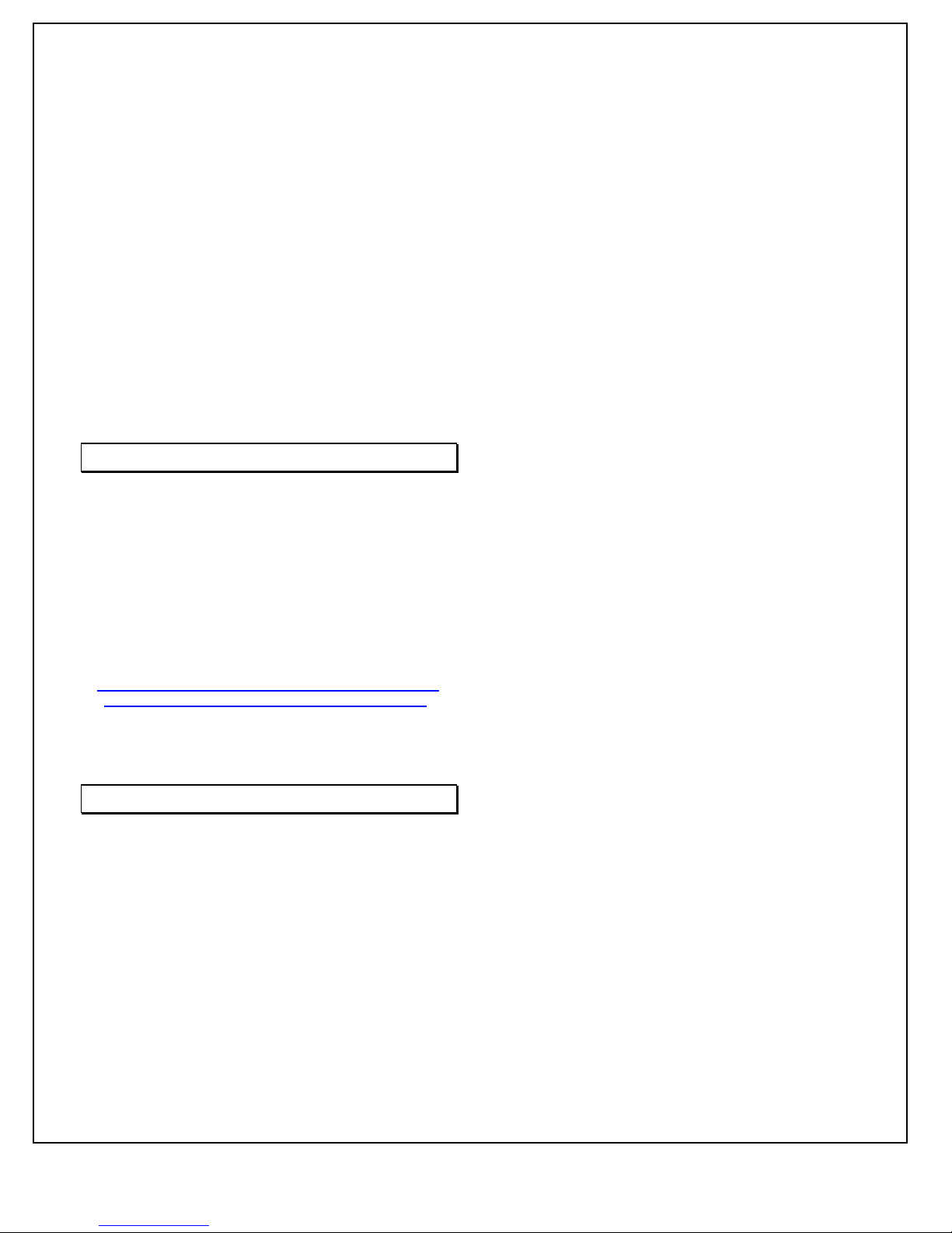
ST/STA/STR SERIES
MODEL :
SERIAL# :
DATE :
SPELLMAN
HIGH VOLTAGE ELECTRONICS
CORPORATION
475 Wireless Blvd.
Hauppauge, New York, 11788
+1(631) 630-3000*FAX: +1(631) 435-1620*
E-mail: sales@spellmanhv.com
Website: www.spellmanhv.com
High Voltage Power Supply
ST/STA/STR SERIES MANUAL 118108-001 Rev C
Page 2

IMPORTANT SAFETY PRECAUTIONS
SAFETY
THIS POWER SUPPLY GENERATES VOLTAGES THAT ARE DANGEROUS AND MAY BE FATAL.
OBSERVE EXTREME CAUTION WHEN WORKING WITH THIS EQUIPMENT.
High voltage power supplies must always be grounded.
Do not touch connections unless the equipment is off and the
Capacitance of both the load and power supply is discharged.
Allow five minutes for discharge of internal capacitance of the power supply.
Do not ground yourself or work under wet or damp conditions.
SERVICING SAFETY
.
Maintenance may require removing the instrument cover with the power on.
Servicing should be done by qualified personnel aware of the electrical hazards.
WARNING note in the text call attention to hazards in operation of these units
that could lead to possible injury or death.
CAUTION notes in the text indicate procedures to be followed to avoid possible
damage to equipment.
Copyright © 2000, Spellman High Voltage Electronics Corporation. All Rights Reserved.
This information contained in this publication is derived in part from proprietary and patent data. This information has
been prepared for the express purpose of assisting operating and maintenance personnel in the efficient use of the
model described herein, and publication of this information does not convey any right to reproduce it or to use it for
any purpose other than in connection with installation, operation, and maintenance of the equipment described.
118004-001 REV. B
Page 3

WICHTIGE SICHERHEITSHINWEISE
SICHERHEIT
DIESES HOCHSPANNUNGSNETZTEIL ERZEUGT LEBENSGEFÄHRLICHE HOCHSPANNUNG.
SEIN SIE SEHR VORSICHTIG BEI DER ARBEIT MIT DIESEM GERÄT.
Das Hochspannungsnetzteil muß immer geerdet sein.
Berühren Sie die Stecker des Netzteiles nur, wenn das Gerät ausgeschaltet ist und die elektrischen
Kapazitäten des Netzteiles und der angeschlossenen Last entladen sind.
Die internen Kapazitäten des Hochspannungsnetzteiles benötigen ca. 5 Minuten, um sich zu entladen.
Erden Sie sich nicht, und arbeiten Sie nicht in feuchter oder nasser Umgebung.
SERVICESICHERHEIT
Notwendige Reparaturen können es erforderlich machen, den Gehäusedeckel während des Betriebes zu
entfernen.
Reparaturen dürfen nur von qualifiziertem, eingewiesenem Personal ausgeführt werden.
“WARNING” im folgenden Text weist auf gefährliche Operationen hin, die zu Verletzungen oder zum Tod
führen können.
“CAUTION” im folgenden Text weist auf Prozeduren hin, die genauestens befolgt werden müssen, um
eventuelle Beschädigungen des Gerätes zu vermeiden.
118004-001 REV. B
Page 4

PRECAUTIONS IMPORTANTES POUR VOTRE SECURITE
CONSIGNES DE SÉCURITÉ
CETTE ALIMENTATION GÉNÈRE DES TENSIONS QUI SONT DANGEUREUSES ET PEUVENT ÊTRE FATALES.
OYEZ EXTRÊMENT VIGILANTS LORSQUE VOUS UTILISEZ CET ÉQUIPEMENT.
S
Les alimentations haute tension doivent toujours être mises à la masse.
Ne touchez pas les connectiques sans que l’équipement soit éteint et que la capacité à la fois de la charge et de
l’alimentation soient déchargées.
Prévoyez 5 minutes pour la décharge de la capacité interne de l’alimentation.
Ne vous mettez pas à la masse, ou ne travaillez pas sous conditions mouillées ou humides.
CONSIGNES DE SÉCURITÉ EN CAS DE REPARATION
La maintenance peut nécessiter l’enlèvement du couvercle lorsque l’alimentation est encore allumée.
Les réparations doivent être effectuées par une personne qualifiée et connaissant les risques électriques.
Dans le manuel, les notes marquées « WARNING » attire l’attention sur les risques lors de la manipulation de ces
équipements, qui peuvent entrainer de possibles blessures voire la mort.
Dans le manuel, les notes marquées « CAUTION » indiquent les procédures qui doivent être suivies afin d’éviter
d’éventuels dommages sur l’équipement.
118004-001 REV. B
Page 5

IMPORTANTI PRECAUZIONI DI SICUREZZA
SICUREZZA
QUESTO ALIMENTATORE GENERA TENSIONI CHE SONO PERICOLOSE E
POTREBBERO ESSERE MORTALI.
PONI ESTREMA CAUTELA QUANDO OPERI CON QUESO APPARECCHIO.
Gli alimentatori ad alta tensione devono sempre essere collegati ad un impianto di terra.
Non toccare le connessioni a meno che l’apparecchio sia stato spento e la capacità interna
del carico e dell’alimentatore stesso siano scariche.
Attendere cinque minuti per permettere la scarica della capacità interna dell’alimentatore
ad alta tensione.
Non mettere a terra il proprio corpo oppure operare in ambienti bagnati o saturi d’umidità.
SICUREZZA NELLA MANUTENZIONE.
Manutenzione potrebbe essere richiesta, rimuovendo la copertura con apparecchio
acceso.
La manutenzione deve essere svolta da personale qualificato, coscio dei rischi elettrici.
Attenzione alle AVVERTENZE contenute nel manuale, che richiamano all’attenzione ai
rischi quando si opera con tali unità e che potrebbero causare possibili ferite o morte.
Le note di CAUTELA contenute nel manuale, indicano le procedure da seguire per evitare
possibili danni all’apparecchio.
118004-001 REV. B
Page 6

Table of Contents
1. INTRODUCTION
1.1 Description of the ST/STR/STA Series ...............................................................1
1.2 Standard Features .................................................................................................1
1.2.1 Remote Operating Features.....................................................................2
1.2.2 System Status and Fault Diagnostic Display ..........................................3
1.3 Options .................................................................................................................4
1.4 Interpreting the Model Number ...........................................................................4
2. INSPECTION & INSTALLATION
2.1 Initial Inspection ..................................................................................................5
2.2 Input Requirements ..............................................................................................5
2.3 Mechanical Installation ........................................................................................5
2.4 Airflow Requirements ..........................................................................................5
3. OPERATING INSTRUCTIONS
3.1 Operation..............................................................................................................7
3.2 Standard Features .................................................................................................8
3.3 Digital Interface (RS-232/Ethernet) .....................................................................9
3.4 Reversible Polarity (1-10kV Units Only) ............................................................9
3.5 Multiple Chassis Systems (Power > 12kWs) .......................................................9
PAGE
4. PRINCIPLES OF OPERATION
4.1 Line Rectifier and Filtering ..................................................................................17
4.2 Inverter .................................................................................................................18
4.3 High Voltage Transformer ...................................................................................18
4.4 High Voltage Assembly .......................................................................................18
4.5 System Control PWB ...........................................................................................18
4.6 Front Panel Assembly ..........................................................................................18
4.7 Rear Panel Interface PWB ...................................................................................18
5. OPTIONS
5.1 Blank Front Panel ................................................................................................19
5.2 High Stability .......................................................................................................19
5.3 High Voltage Cable Length .................................................................................19
5.4 400VAC ...............................................................................................................19
5.5 180-264Vac Single Phase Input (1PH) ................................................................19
5.6 Custom Designed Models ....................................................................................19
5.7 Parallel Option Units............................................................................................20
6. MAINTENANCE
6.1 Periodic Servicing ................................................................................................22
ST/STR/STA MANUAL i 118107-001 REV J
Page 7

6.2 Performance Test .................................................................................................22
6.3 High Voltage Dividers .........................................................................................22
7. REPLACEMENT PARTS
7.1 Replacement Parts ................................................................................................23
7.2 Correspondence and Ordering Spare Parts ..........................................................23
8. FACTORY SERVICE
8.1 Warranty Repairs .................................................................................................23
8.2 Factory Service Procedures ..................................................................................23
8.3 Ordering Options and Modifications ...................................................................23
8.4 Shipping Instructions ...........................................................................................23
APPENDIX
A. RS-232 and Ethernet Digital Interface Information
B. TI Upload Procedure (Firmware Update Procedure)
C. Standard ST GUI Information
D. Specification Control Drawing (Custom Models Only)
LIST OF FIGURES / TABLES
Figure 3.1 Typical Operating Setup ...............................................................................9
Figure 3.2A Remote Programming via Voltage Source ....................................................10
Figure 3.2B Remote Programming via External Resistance..............................................10
Figure 3.3 Remote Monitor Test Point Designations ......................................................11
Figure 3.4 Remote Control Power On, HIGH VOLTAGE ON and HV OFF ................11
Figure 3.5 External Inhibit Interface Circuit ...................................................................12
Figure 3.6 External Interlock Interface Circuit ...............................................................12
Figure 3.7 Remote HIGH VOLTAGE ON and HIGH VOLTAGE OFF .......................13
Figure 3.8 Remote Overvoltage Adjust Interface ...........................................................13
Figure 3.9 Remote Status and Fault Indicator Interface ..................................................14
Figure 3.10 Rear Panel Interface Connecter .....................................................................15
Figure 4.1 List of Main Assemblies ................................................................................16
Table 1 Input Requirements ........................................................................................6
ST/STR/STA MANUAL ii 118107-001 REV J
Page 8
Chapter 1
T
INTRODUCTION
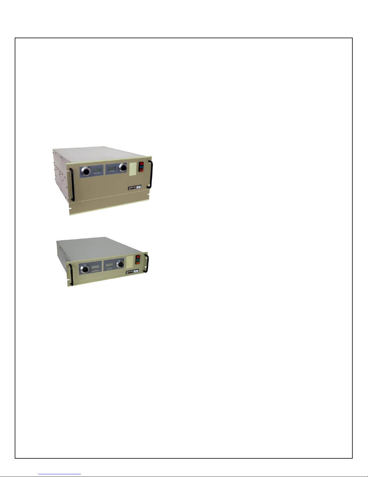
1.1 Description of the
ST/STR/STA Series
ST/STR
STA
he ST series of high voltage power supplies provides
very well regulated, low ripple high voltage in a
highly efficient, compact design. Extremely stable
voltage and current outputs result in significant
performance improvements over previously available
technology.
All of these advancements are possible only by
Spellman’s long history in high voltage power conversion
technology. This series of power supplies utilizes
extremely advanced quasi-resonant PWM conversion
techniques, along with sophisticated digital technology.
The output voltage, current and power are continuously
adjustable over their full rated range. The standard ST
operates from 180-264Vac, three phase power and is
forced air cooled. An optional 360-528Vac input
(400VAC) is available. Custom units to meet special
requirements and specific applications can also be
provided.
The STR Series high voltage power supplies are identical
in form, fit and function to the ST Series the following
exceptions:
1) The STR only provides 6kW’s of output power.
2) The ripple specification for the STR is 0.1% p-p
+1Vrms.
3) It is not possible to parallel STR chassis. If
additional power is required use an ST Series
unit.
4) The SRT is available with an optional 180-
264Vac single phase input voltage.
Aside from these four points, the STR and ST are for all
practical purposes identical. For the sake of clarification
the following text only references ST, but all points apply
to the STR Series as well.
The STA Series of high voltage power supplies are
identical to the ST Series with the following exceptions:
1) The STA is a 5.25 inch tall (3U) chassis.
2) The STR only provides 4kW’s of output power.
3) The ripple specification for the STA is 0.1% p-p
+1Vrms.
4) It is not possible to parallel STA/STR chassis. If
additional power is required use an ST Series
unit.
5) The STA is available with an optional 180-
264Vac single phase input voltage.
Customary warranty terms apply to standard units.
Consult the Spellman Sales Department about the
warranty for custom/X numbered units.
1.2 Standard Features
The ST series incorporates several standard features and
software configurable items designed to optimize user
utility, satisfaction and safety.
FRONT PANEL CONTROL POWER/HIGH
VOLTAGE ON/ HIGH VOLTAGE OFF SWITCHES:
These intuitive front panel controls allow the user to
ST/STR/STA MANUAL 1 118107-001 REV J
Page 9
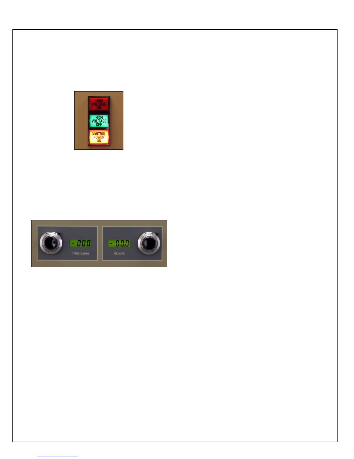
easily turn the unit on and enable/disable the generation
of high voltage.
FRONT PANEL INDICATOR LAMPS: CONTROL
POWER ON, HIGH VOLTAGE OFF and HIGH
VOLTAGE ON indicators are integral with the control
switches and equipped with dual lamps for redundancy
and safety.
displaying an “ARC” Fault (Arc Trip). See Chapter 3 for
operating details and information for user customization
for these parameters via the software and the digital
interface.
INTERNAL FAULT PROTECTION: The ST series
continually monitors internal circuits critical to the proper
operation of the power supply. In the event that one of
these circuits malfunctions, the fault detection circuit
turns off the high voltage and reverts the unit to the
POWER DOWN mode with the CONTROL POWER ON
indicator lamp flashing ON/OFF slowly. The applicable
fault indicator will be illuminated on the front panel
requiring the user to clear (cycle the CONTROL POWER
ON switch, cycle the AC line power or toggle the
Reset/External Inhibit signal line).
FRONT PANEL POTENTIOMETERS: Ten turn
locking counting dials are provided for easy programming
of the desired voltage and current regulation values.
FRONT PANEL DIGITAL METERS: 3.5 digit meters
are provided to view the output voltage and current. A
convenient Preset View Feature is provided: If the HIGH
VOLTAGE OFF button is depressed and held in, the
present voltage and current programming values will be
displayed in actual kV and mA on the front panel meters.
ETHERNET AND RS-232 INTERFACE: DSP based
SMT circuitry provides both Ethernet and RS-232 digital
interfacing capability simplifying the integration of the
ST into your system design. A VB GUI is provided for
the RS-232, the Ethernet has an imbedded applet for
control.
SLOW START RAMP TIME: This feature provides a
gradual increase of high voltage until the preset operating
point is reached. The slow start time is factory set for ten
seconds. Other slow start times can be software
configured using the digital interface.
ARC QUENCH/ARC RERAMP/ARC TRIP: These
features allow the user to tailor the power supply to meet
specific needs in dynamic load applications. The standard
configuration is if an arc occurs, the output is inhibited for
approximately 200mS (Arc Quench), and then the output
is ramped up to the preset level with the Slow Start
circuitry time constant (Arc ReRamp). If four arcs occur
in a ten second time period the unit will shut down
OUTPUT CABLE: All standard models are provided
with a ten foot shielded high voltage output cable. The
cable is designed so that it can be easily removed from the
mating receptacle located on the rear of the chassis.
1.2.1 Remote Operating Features
REMOTE PROGRAMMING: Allows remote
adjustment of the output voltage, current, power and
overvoltage regulation parameters via the use of external
voltage sources.
REMOTE MONITOR: Allows remote monitoring of
the output voltage, current and power test points.
REMOTE HIGH VOLTAGE CONTROL: Allows
remote control of the HIGH VOLTAGE ON and HIGH
VOLTAGE OFF functions. Signals are also provided for
remote indication of HIGH VOLTAGE ON and HIGH
VOLTAGE OFF status.
REMOTE POWER ON: Allows remote control of
CONTROL POWER ON/OFF function. This feature also
allows remote reset of the power supply in case of
SYSTEM FAULT shutdown.
RESET/EXTERNAL INHIBIT: This circuit will reset
any latched power supply faults and inhibit the high
voltage output. A logic low/ground, will reset any fault(s)
while inhibiting the high voltage output. A logic
high/open will restore the high voltage output to the
preset level. NOTE: The External Inhibit circuit should
NOT be used for protection against injury or for safety
interlocking. See External Interlock for this type of safety
control.
EXTERNAL INTERLOCK: Interlock connections are
provided on the rear panel interface connecter for
connection to a safety switch. The unit will not operate
unless the interlock circuit is closed. During high voltage
operation, opening the interlock circuit will cause the
ST/STR/STA MANUAL 2 118107-001 REV J
Page 10
High Voltage to shut off. This circuit should be used for
safety interlock circuits. Spellman strongly recommends
the use of External Interlocking for safety purposes.
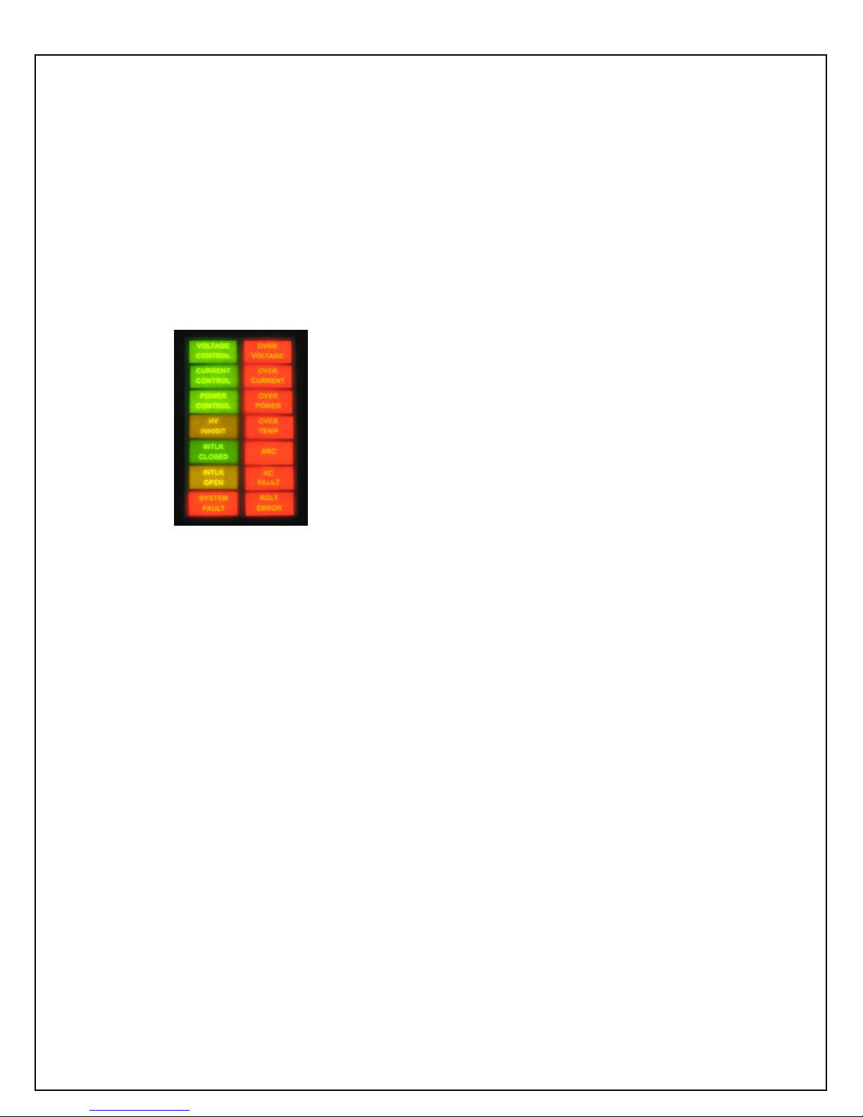
1.2.2 System Status and Fault
Diagnostic Display
“Dead Front” backlight type indicators provide system
operation and fault condition information. If a fault occurs
the power supply will revert to the POWER DOWN
mode. This is indicated by the flashing of the CONTROL
POWER ON indicator. To reset the latched fault: cycle
the CONTROL POWER ON switch, cycle the AC line
power or toggle the Reset/External Inhibit signal line.
VOLTAGE CONTROL: Indicates the output voltage
regulator circuit is maintaining voltage regulation.
CURRENT CONTROL: Indicates the output current
regulator circuit is maintaining current regulation.
voltage by the user via the remote overvoltage
programming capability, see Chapter 3 for more details.
OVER CURRENT: Indicates the output current has
exceeded the programmed current trip level when the
AOL (Adjustable Overload Trip) feature has been
software configured using the digital interface.
OVER POWER: Indicates the output power has
exceeded the programmed regulating level. This signal
could be either the internal potentiometer or the user
provided remote power programming signal, dependent
on configuration.
OVER TEMP: Indicates that excessive temperature has
been sensed within the chassis and internal protection
circuitry has shut down the power supply.
ARC: Indicates that an arc has occurred (one second
flash) or that the ARC Intervention Circuitry has
shutdown the power supply due to excessive arcing
(latched “ARC” fault).
AC FAULT: Indicates a problem with the front end AC
input circuitry and the corresponding generated inverter
buss voltages.
RGLT ERR: Indicates a failure in the voltage, current or
power regulation circuitry. This fault usually occurs
when there is a lack of output power to maintain proper
regulation. Possible causes could be due to low AC input
voltage (below low line parameters, or a missing phase)
or a malfunction of the power supply preventing it from
generating the voltage/current being requested.
POWER CONTROL: Indicates the output power
regulator circuit is maintaining power regulation.
HV INHIBIT: Indicates the high voltage supply is being
inhibited by either the EXTERNAL INHIBIT signal line
or by internal protection circuitry.
INTLK CLOSED: Indicates the EXTERNAL
INTERLOCK connections are in the closed position.
INTLK OPEN: Indicates the EXTERNAL
INTERLOCK connections are in the open position. This
also indicates opening of internal power supply interlocks.
It is not possible to enable HIGH VOLTAGE with an
open EXTERNAL INTERLOCK.
SYSTEM FAULT: Indicates an internal fault or parallel
chassis fault (in multiple chassis systems) has occurred.
OVER VOLTAGE: Indicates the overvoltage protection
circuitry has caused the power supply to turn off. The
default setting for the overvoltage protection circuitry is
internally set to 105% of rated output voltage. This level
can be set to anywhere from 0- 105% of rated output
ST/STR/STA MANUAL 3 118107-001 REV J
Page 11
1.3 Options
BFP Blank Front Panel
Local control functionality and metering is removed from
the standard front panel, a popular cost saving measure
for OEM applications where the unit will only be
controlled remotely.
HS High Stability
The standard voltage feedback divider is replaced with a
high precision voltage feedback divider providing a
50ppm/°C temperature coefficient specification.
LL(X) High Voltage Cable Length
Custom length high voltage output cables, indicated in
foot measurement units. Various predetermined lengths
are available along with entirely custom lengths; contact
Spellman Sales Department for details.
400VAC 360-528Vac Input
This option factory configures the ST/STR to operate
from 360-528Vac, three phase, 50/60Hz input power.
This option cannot be implemented in the field.
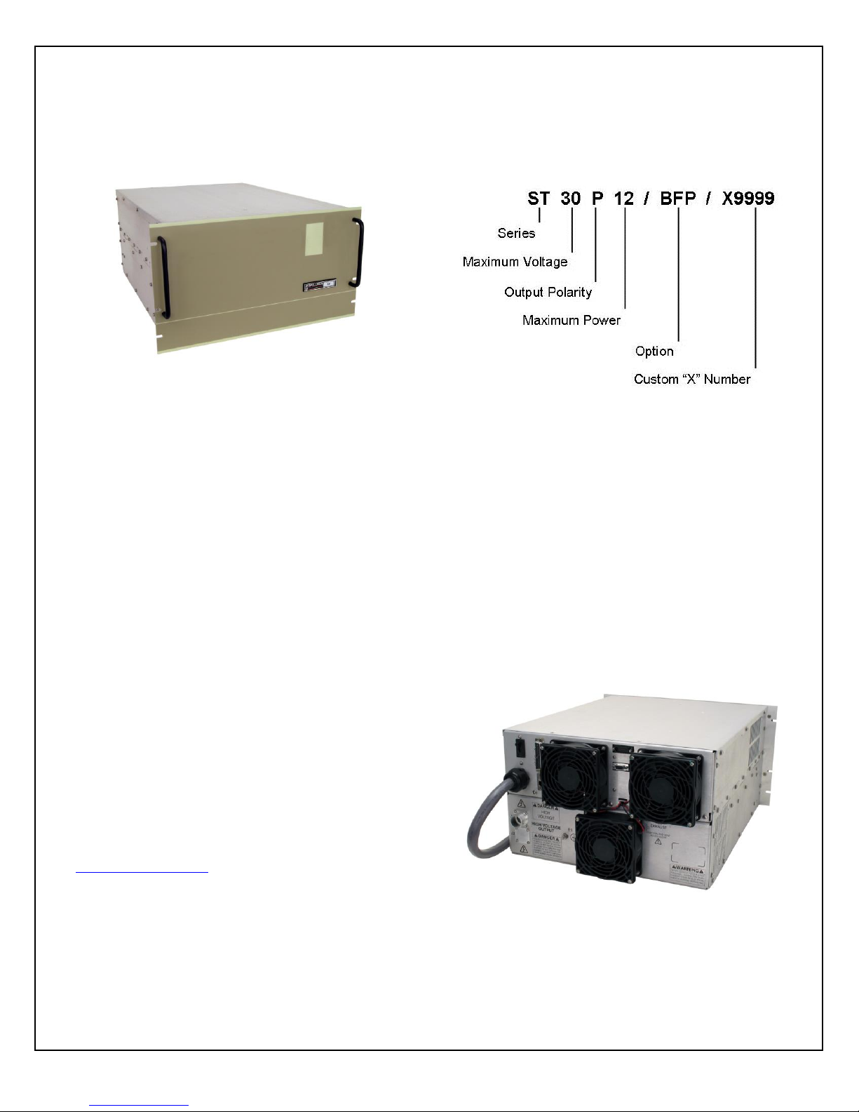
1.4 Interpreting the Model
Number:
The model number of the power supply describes its
capabilities. After the series name “ST” is:
● The maximum voltage in kV
● The polarity of the unit: positive (P) or negative (N). 1-
10kV units are inherently reversible by design requiring
and internal wiring change to swap polarity. All units
required a polarity selection to be made at time of order.
● The maximum output power in kilowatts
● The option codes for all options that are included.
● Custom units have a unique 4 digit X number after the
option code(s). This X number references a unique
specification control drawing that takes precedent over
the standard ST data sheet specifications.
1PH Single Phase Input
Optional 180-264Vac single phase input voltage,
available only on STR and STA.
See Section 5 for more information on these options.
With few exceptions, these options can be retrofitted to
your power supply at the factory in a short time. For price
and retrofit arrangements, contact Spellman’s Sales
Department at:
sales@spellmanhv.com
ST/STR/STA MANUAL 4 118107-001 REV J
Page 12
Chapter 2
I
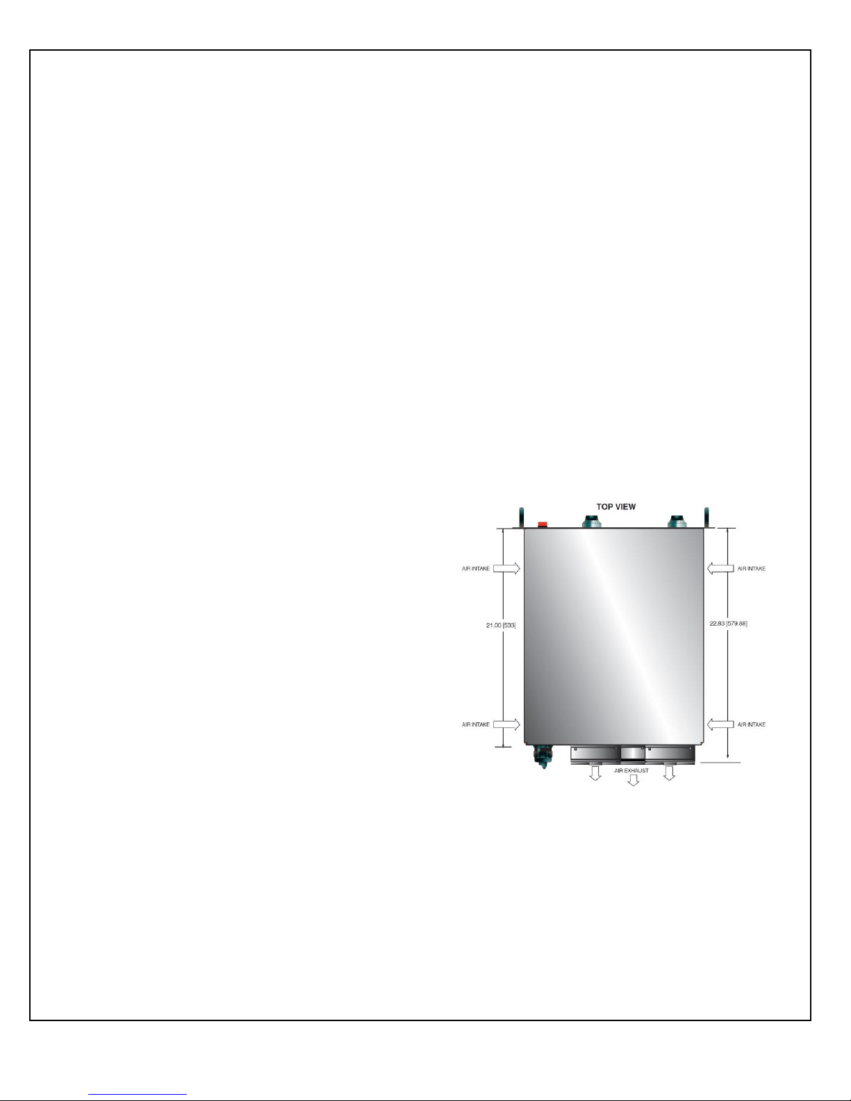
Figure 2.1 ST/STR/STA
Airflow
Inspection and Installation
nitial inspection and preliminary checkout procedures
are recommended. For safe operation, please follow
the step-by-step procedures described in Chapter 3,
Operating Instructions.
2.1 Initial Inspection
Inspect the package exterior for evidence of damage due
to handling in transit. Notify the carrier and Spellman
immediately if damage is evident. Do not destroy or
discard any of the packing material used in a damaged
shipment.
After unpacking, inspect the panel and chassis for visible
damage.
Standard Spellman ST high voltage power supplies are
covered by a warranty. Custom and special order models
(with an X suffix in the model number) are also covered
by a warranty. Check the specific warranty terms by
referring to the Warranty document contained in this
operator’s manual.
2.2 Input Requirements
Units ordered with the 400VAC Option (360-528Vac)
do NOT have a rear panel circuit breaker. For proper
protection of the ST power supply a circuit breaker
protected, dedicated three phase electrical service must
be provided for each ST chassis. ST units are not phase
dependent; the three AC input phase connections can be
orientated in any manner with no adverse effect on
power supply performance. SEE TABLE 1
suitable for bench or tabletop operation. It is
strongly recommended to support the chassis by
guides or shelves.
2.4 Airflow Requirements
ST units are forced air cooled, air enters the
chassis via openings on the right and left side
panels and air is forcibly exhausted out the rear
panel via three fans. Whatever mechanical
installation is implemented airflow into and out
of the unit must not be compromised.
Additionally it is the responsibility of the user to
assure that air entering the unit is not above the
maximum ambient temperature of 40°C.
Airflow volume is 300cfm for ST units, 200 cfm
for STR units and 100 cfm for STA units.
2.3 Mechanical Installation
Units in the ST series have front panel holes for standard
EIA rack mounting. The rack must allow rear access for
cable connections. Units are fully enclosed and are
ST/STR/STA MANUAL 5 118107-001 REV J
Page 13
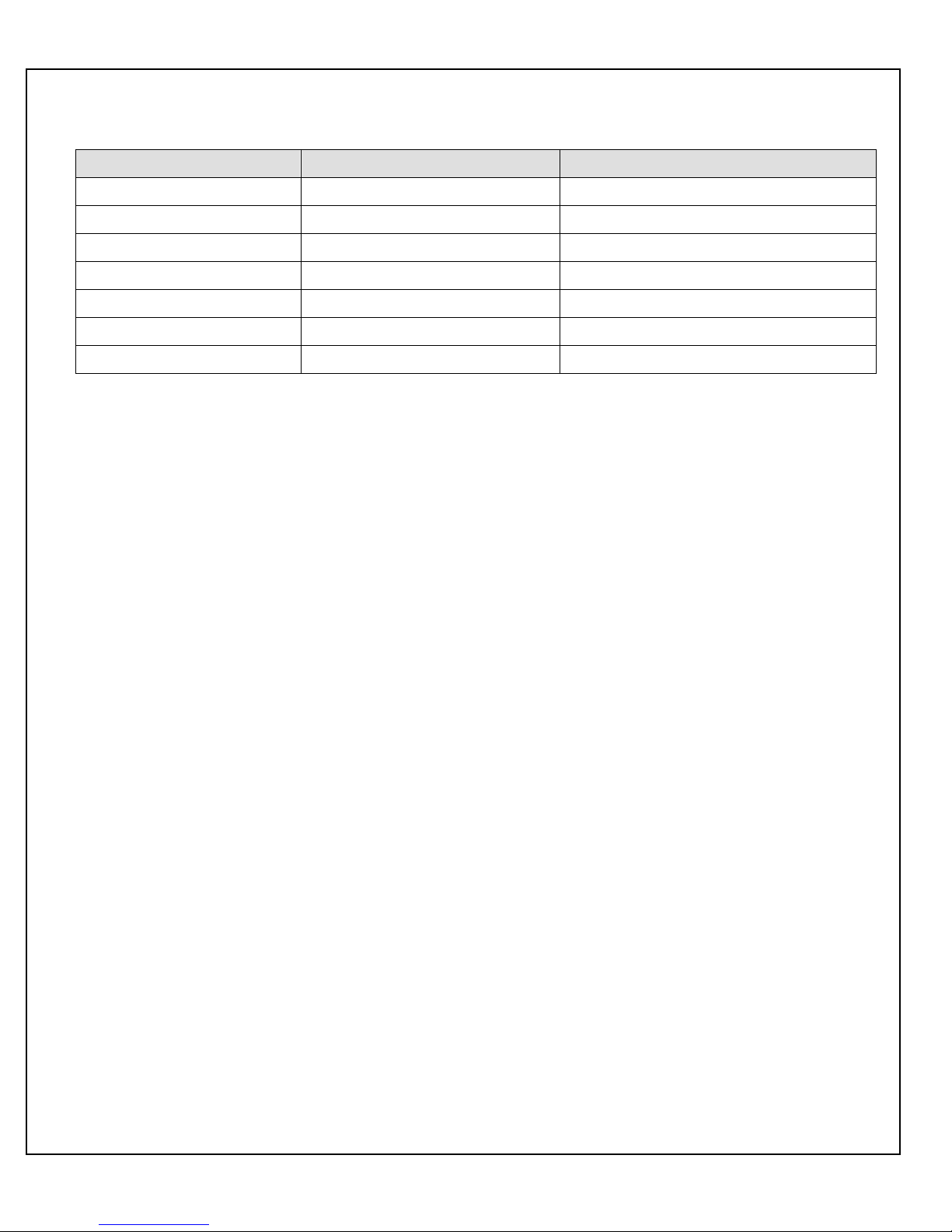
UNIT/INPUT VOLTAGE
FACTORY CONFIGURATION
MAXIMUM INPUT CURRENT PER PHASE
ST 180-264Vac, 3 phase
Standard
50 amps
ST 360-528Vac, 3 phase
Optional (400Vac)
25 amps
STR 180-264Vac, 3 phase
Standard
25 amps
STR 360-528Vac, 3 phase
Optional (400Vac)
12.5 amps
STR 180-264Vac, 1 phase
Optional (1PH)
57 amps
STA 180-264Vac, 3 phase
Standard
17 amps
STA 180-264Vac, 1 phase
Optional (1PH)
38 amps
Table 1 Input Requirements
ST/STR/STA MANUAL 6 118107-001 REV J
Page 14
Chapter 3
Operating Instructions
3.1 Operation
WARNING
THIS EQUIPMENT GENERATES
DANGEROUS VOLTAGES THAT MAY BE
FATAL. PROPER GROUNDING OF ALL
HIGH VOLTAGE EQUIPMENT IS ESSENTIAL.
WARNING
BEFORE CONNECTING THE POWER
SUPPLY TO THE AC LINE, FOLLOW THIS
STEP-BY-STEP PROCEDURE.
DO NOT CONNECT THE POWER SUPPLY
TO THE AC LINE UNTIL STEP ‘G’ IS
REACHED. FAILURE TO FOLLOW THESE
PROCEDURES MAY VOID THE WARRANTY.
A) Insure that the front panel CONTROL POWER
ON switch is in the OFF position (switch bezel out).
B) Check the input voltage rating on the nameplate
of the supply and make certain that this is the rating of the
available power source.
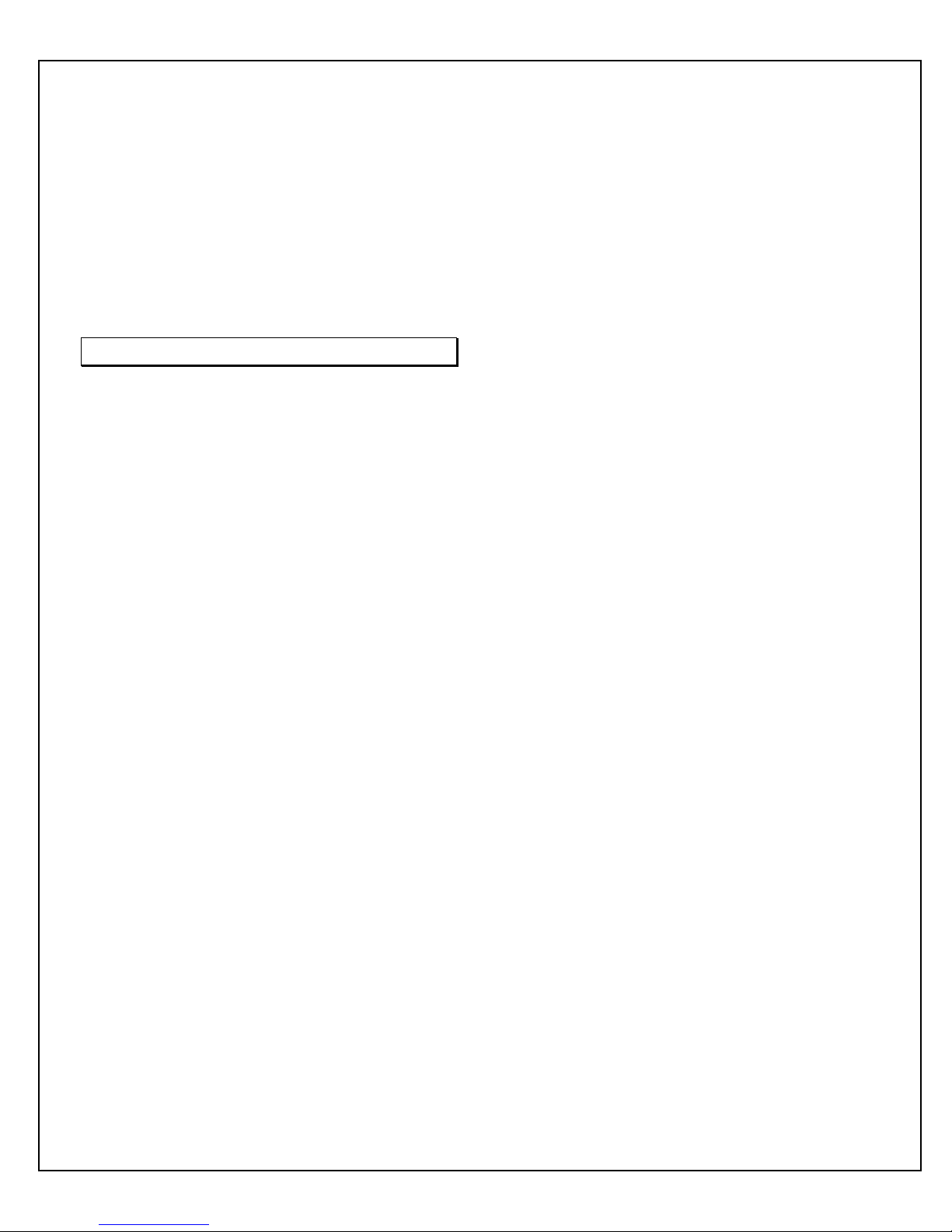
C) PROPER GROUNDING TECHNIQUE: The
chassis of high voltage power supply must be adequately
grounded, preferably to the local “system ground” (cold
water pipe ground, electrical conduit ground, copper
ground rod, etc) using a heavy gauge copper wire
securely connecting to the ¼-20 ground stud on the rear
panel of the of the unit. See Figure 3.1 for a typical
operating setup.
A heavy gauge user provided “load return” wire must be
connected from the low end of the load back to the ¼-20
ground stud on the rear panel of the power supply. Using
a separate external ground at the load is not
recommended.
A six foot long, captive, four-wire, unterminated line cord
is provided for connecting to the AC supply. The
BROWN, BLACK and BLUE wires are the three phase
inputs. The GREEN/YELLOW wire is for chassis safety
ground connection. This is a safety ground connection
and is NOT adequate for system grounding purposes.
Attach the output cable to the load.
D) Plug the high voltage output cable provided with
the unit into the rear of the supply and secure
appropriately.
E) Options Note: See section 5 for hook up and
operating instructions for the options on your unit.
Custom models may also require set up changes.
F) For initial turn-on, rotate the front panel
KILOVOLT control potentiometer fully counterclockwise to the zero voltage position.
G) The input power cable may now be connected to
the AC power line.
H) Depress the CONTROL POWER ON switch.
The green light inside the switch should light up. The
unit is now in the HIGH VOLTAGE OFF mode. The
HIGH VOLTAGE OFF light should be lit.
I) Depress and hold the HIGH VOLTAGE OFF
switch. The front panel meters will now read the preset
value of the KILOVOLT control dial and the
MILLAMPERES control dial. To preset the desired level
of the current and voltage during operation, hold the
HIGH VOLTAGE OFF switch and rotate the appropriate
control dial while noting its corresponding meter reading.
Release the HIGH VOLTAGE OFF switch.
NOTE: No actual high voltage is being produced at this
time.
J) Depress the HIGH VOLTAGE ON switch. The
red light inside the switch should illuminate and the
output will slow start up to the preset level output voltage
and/or output current.
Note: The ST series is equipped with a slow start circuit
that ramps the output up to its maximum setting in
approximately 10 seconds after the HIGH VOLTAGE
ON switch is depressed.
K) To terminate the generation of output power,
depress the HIGH VOLTAGE OFF switch. In the HIGH
VOLTAGE OFF mode the power supply’s fault and
interface circuits are still active.
L) To turn off the power supply, depress the
CONTROL POWER ON switch to release the switch
bezel to the out position. All front panel lights should
extinguish.
ST/STR/STA MANUAL 7 118107-001 REV J
Page 15
NOTE: If a power supply fault, or system monitoring
fault occurs, the power supply will revert to the POWER
DOWN mode. In this mode the output power will be
turned off. The CONTROL POWER ON lamp will flash
indicating a SYSTEM FAULT. To reset the SYSTEM
FAULT cycle the CONTROL POWER ON switch, cycle
the AC line power or toggle the RESET/EXTERNAL
INHIBIT signal line.
WARNING
AFTER TURNOFF, DO NOT HANDLE THE LOAD
UNTIL THE CAPACITANCE HAS BEEN
DISCHARGED! LOAD CAPACITANCE MAY BE
DISCHARGED BY SHORTING TO GROUND.
WARNING
THE VOLTMETER ON THE POWER SUPPLY
FRONT PANEL DOES NOT READ THE OUTPUT
VOLTAGE WHEN THE POWER IS TURNED OFF,
EVEN IF A CHARGE STILL EXISTS ON THE
LOAD.
CAUTION
TO ASSURE SAFETY AND PROPER COOLING
ALWAYS OPERATE THE UNIT WITH THE COVER
PANELS INSTALLED.
Fans maintain safe operating temperatures in the power
supply by drawing air over the circuit components. The
covers must be on in order to direct the air flow over the
areas that need cooling. In operation, the units air intake
and fan exhaust paths must be clear of any obstructions
that might impede the flow of air.
3.2 Standard Features
A general note on remote interface circuitry and remote
signal grounding:
When usage applications dictate, electrical isolation may
be required when interfacing with high voltage power
supply in question. For power control signals such as
CONTROL POWER, EXTERNAL INTERLOCK, HIGH
VOLTAGE OFF and HIGH VOLTAGE ON isolated
relay contacts should be used. For status signals and
control signals such as HIGH VOLTAGE ON, HIGH
VOLTAGE OFF, EXTERNAL INHIBIT, etc. optoisolation should be used. When usage applications dictate,
analog programming and monitoring signals may require
isolation via analog isolation amplifiers. All interface
cables should be properly shielded. All power supply
signals should be referenced to the power supplies signal
ground on the rear panel interface connecter.
LOCAL/REMOTE PROGRAMMING: Allows
adjustment of the output voltage, current and power via
the front panel/internal controls (local) or external voltage
sources (remote).
LOCAL CONTROL - In local control (front panel
control), jumpers are installed on rear panel interface
connecter between pin 8 and pin 9 for current control;
between pin 10 and pin 11 for voltage control and
between pin 42 and pin 43 for power control. This will
enable the front panel potentiometers for current/voltage
control and the internal potentiometer for power control.
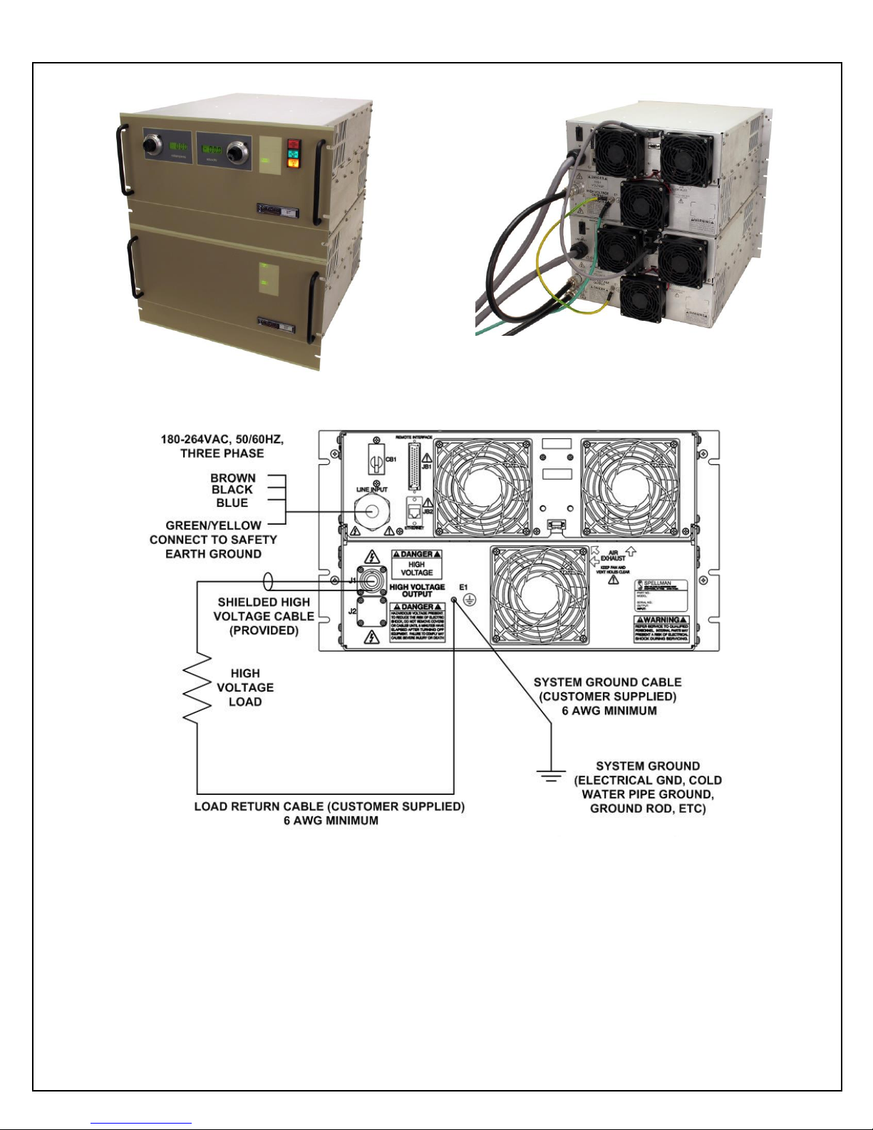
REMOTE CONTROL - For remote programming, the
above mentioned jumpers are removed and a positive
polarity, ground referenced voltage source is applied to
the pin 8 for current, pin 10 for voltage and pin 42 for
power. Programming signals should be referenced to pin
1, signal ground. Scaling is such that 0-10Vdc
corresponds to 0-100% rated output respectively. See
Figure 3.2A for wiring diagram.
An alternate method of controlling the output remotely is
by using external resistance such as a potentiometer or a
resistor network. For remote control the jumpers are
removed and the desired resistor configuration is
installed. See Figure 3.2B for wiring diagram.
REMOTE MONITORS: Test points are made available
on the rear panel interface connecter for monitoring the
current, voltage and power; pin 5, pin 6 and pin 25
respectively. The test points are always positive
regardless of the output polarity, scaling is such that 010Vdc corresponds to 0-100% rated output respectively.
Test points have an output impedance of 1k ohms, ±1%.
See Figure 3.3 for test point designation.
LOCAL/REMOTE CONTROL POWER / HIGH
VOLTAGE ON / HV OFF: Allows for command of
CONTROL POWER, HIGH VOLTAGE ON and HIGH
VOLTAGE OFF by either the front panel controls or
external signals via the rear panel external interface
connecter.
LOCAL CONTROL - For local front panel switch
command of the Control Power functionality a maintained
connection between pin 12 and pin 13 is required. Once
connected as outlined above, the front panel CONTROL
POWER switch will alternate latch on/latch off with each
successive pressing of the switch. For local front panel
command of the HIGH VOLTAGE OFF functionality a
maintained connection between pin 14 and pin 15 is
required.
REMOTE CONTROL – Remote control of CONTROL
POWER, HIGH VOLTAGE ON and HIGH VOLTAGE
OFF can be accomplished via the rear panel interface.
The CONTROL POWER is an on-off toggle contact
between pins 12 and 13. With the front panel CONTROL
POWER switch latched in the “ON” position, opening
and closing the connection between pins 12 and pins 13
will allow remote command of the CONTROL POWER
ST/STR/STA MANUAL 8 118107-001 REV J
Page 16
functionality. HIGH VOLTAGE OFF and HIGH
VOLTAGE ON are controlled by momentary normally
closed, normally open contacts, respectively between pins
14 and 15, and pins 15 and 16. See Figure 3.4 for
recommended interface.
EXTERNAL INHIBIT: The External inhibit allows the
user to inhibit the power supply output without putting the
power supply into the HIGH VOLTAGE OFF mode.
This circuit can be used to generate fast slewing output
waveforms or control high voltage generation as in Laser
and Capacitor discharge applications. The maximum
inhibit rate should not exceed 5Hz. Consult factory for
higher repetition rates or high pulse load applications.
See Figure 3.5 for the recommended interface circuit.
WARNING
IT IS EXTREMELY DANGEROUS TO USE THE
EXTERNAL INHIBIT TO STOP HIGH VOLTAGE
GENERATION FOR THE PURPOSE OF
SERVICING OR APPROACHING ANY AREA OF
THE LOAD CONSIDERED UNSAFE DURING
HIGH VOLTAGE OPERATION
EXTERNAL INTERLOCK: The External Interlock
connections are provided on the rear panel interface
connecter, pin 3 and pin 4, intended for use in the
connection to a customer provided and implemented
external safety switch. The unit will not operate unless
the interlock circuit is closed. If the interlock is not being
used (use is highly recommended), a jumper must be
installed. During high voltage operation, opening the
External Interlock will cause the unit to revert to the
HIGH VOLTAGE OFF mode. Subsequent closing of the
interlock circuit will NOT return the unit to HIGH
VOLTAGE ON mode; this must be accomplished by
depressing the HIGH VOLTAGE ON switch. See Figure
3.6 for the recommended interface circuit.
ARC DETECT / ARC QUENCH /ARC COUNT: The
ARC Intervention Circuitry senses dynamic arcing or
discharge conditions present at the output load with a
wide bandwidth current transformer coupled to the return
side of the high voltage multiplier.
The instant an arc is detected the generation of high
voltage is electronically inhibited for 200mS; this is called
the ARC Quench time period. After the 200mS period,
the discharged HV output (level dependent upon arc
impedance, arc duration, etc) is ramped back up to the
previous set level. This ramp time is based on the
standard 200mS Slow Start time constant. The ARC
indicator on the front panel will illuminate for
approximately 500mS after each arc has occurred. The
HV INHIBIT indicator will also illuminate for 500mS
indicating that the output is being inhibited (ARC
Quench).
The factory default setting of the Arc Intervention
circuitry is such that if four arcs occur in a ten second
time period the unit will shut down into the POWER
DOWN mode displaying an “ARC Fault”. ARC
parameters can be modified by using the digital interface
and provided GUI but changing these settings can have
serious consequences.
NOTE: Making changes to the ARC Intervention
Circuitry along with excessive arcing of the power supply
can thermally overheat and damage the internal short
circuit limiting assembly. Damage to the power supplies
internal short circuit limiting assembly is consider misuse
of the unit and repairs will not be covered under the
warranty. The ARC Intervention Circuitry is incorporated
and configured to protect the power supply from
excessive arcing, make changes to this circuitry at your
own responsibility and risk.
REMOTE HIGH VOLTAGE ON & REMOTE HIGH
VOLTAGE OFF: Signals are provided for remote
monitoring of the HIGH VOLTAGE ON and HIGH
VOLTAGE OFF status. See Figure 3.7 for recommended
interface.
3.3 Digital Interface (RS-
232/Ethernet)
The ST features standard RS-232 and Ethernet digital
interface capability. Please see Appendix A for complete
details on functionality and operation.
3.4 Reversible Polarity (1-10kV
Units Only) ST/STR Only
1 to 10kV units are inherently reversible by design but
still require a polarity selection to be made at time of
order. These units are air insulated and a simple wiring
change made in the high voltage multiplier section can
convert a positive polarity unit to a negative polarity unit,
or vice versa.
3.5 Multiple Chassis Systems –
ST Only
Additional ST chassis can be connected in parallel to
achieve multiple 12kW increments of power to above and
beyond 100kW’s in a factory configured Master/Slave
arrangement. The Master unit retains its full feature front
panel while the Slave unit(s) have a Blank Front panel.
From an interfacing and functionality standpoint the
multiple chassis system behaves effectively like a single
chassis higher power unit. This technique provides
commonality of physically manageable hardware units
and possibility redundancy further enhancing system
uptime and reliability.
ST/STR/STA MANUAL 9 118107-001 REV J
Page 17
Typical Multiple Chassis Configuration
Note: 400VAC units do not have an internal circuit breaker. The service connection to these units
must be protected by an appropriately rated and circuit breaker protected power connection.
Figure 3.1 Typical Operating Setup ST
ST/STR/STA MANUAL 10 118107-001 REV J
Page 18
1
2
3
4
5
6
7
8
9
10
11
DC
DC
Remote
Current
Program
Remote
Voltage
Program
Rear Panel JB1
Zin = 10M ohms
Zin = 10M ohms
Voltage Source:
0 to 10Vdc = 0 to 100% Rated Output
All cables should be shielded with
the shields returned to chassis
ground (E1) of the high voltage
power supply
DC
Remote
Power
Program
42
Zin = 10M ohms
1
2
3
4
5
6
7
8
9
10
11
Remote
Current
Control
Remote
Voltage
Control
Rear Panel JB1
Zin = 10M ohms
Zin = 10M ohms
Potentiometer Settings:
Fully Counterclockwise = Zero Output
Fully Clockwise = 100% of Rated Output
All cables should be shielded
with the shields returned to
chassis ground (E1) of the
high voltage power supply.
50k Ohm50k Ohm
+10Vdc
Power Supply Ground
42
Remote
Power
Control
50k Ohm
Zin = 10M ohms
Figure 3.2A Wiring Diagram for Remote Programming via Voltage Source
____________________________________________________________________________________
ST/STR/STA MANUAL 11 118107-001 REV J
Figure 3.2B Wiring Diagram for Remote Programming via External Resistance
Page 19
1
2
3
4
5
6
7
Rear Panel
JB1
Zout = 1k ohm, ±1%
Zout = 1k ohm, ±1%
Power Supply Ground
MM
+ +
--
Current
Monitor
Voltage
Monitor
25
M
+
-
Power
Monitor
Zout = 1k ohm, ±1%
Figure 3.3 Remote Monitor Test Point Designations
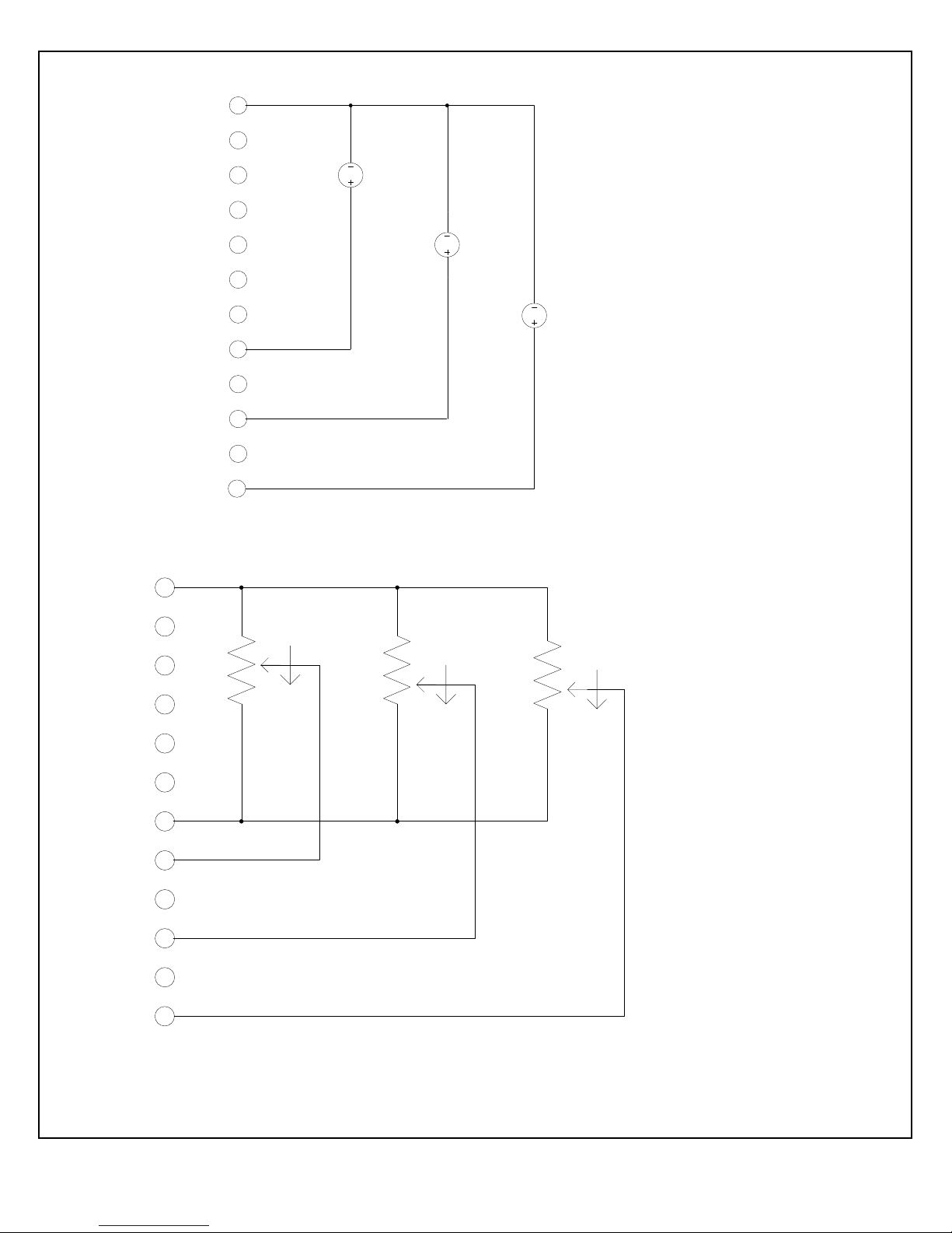
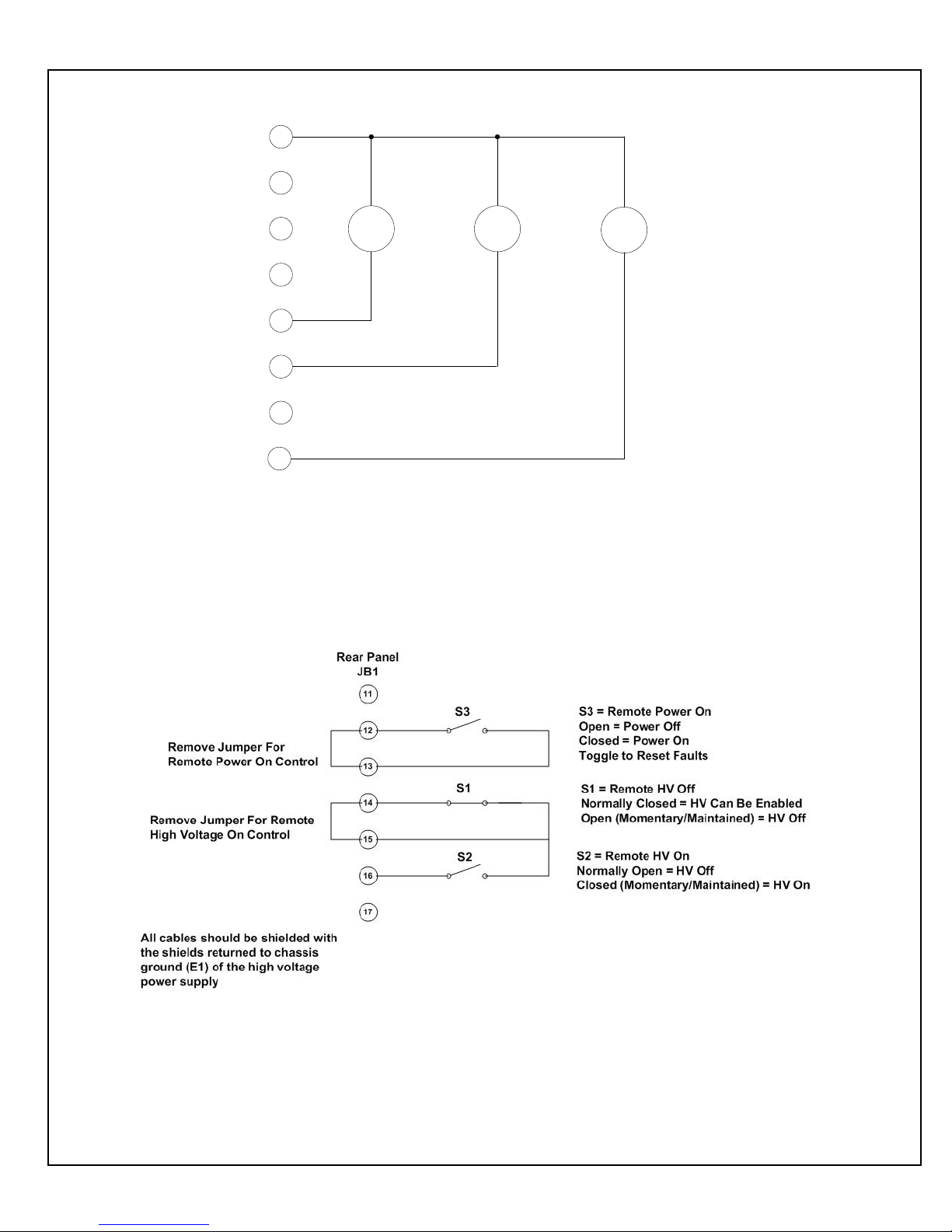
It is recommended to use relay contacts for S1, S2 and S3.
Relays should be located as close as possible to the high
voltage power supply. Coils should be driven from
isolated sources. Signals are at ~24V, 100mA max, and
are only to be used for contact closure.
S1 must be closed to enable HIGH VOLTAGE ON.
Momentary closure of S2 will enable HIGH VOLTAGE
ON.
Opening S1 will disable HIGH VOLTAGE ON and
switch the unit to the HIGH VOLTAGE OFF mode.
ST/STR/STA MANUAL 12 118107-001 REV J
Figure 3.4 Remote Control of Power ON, High Voltage ON and High Voltage OFF
Page 20
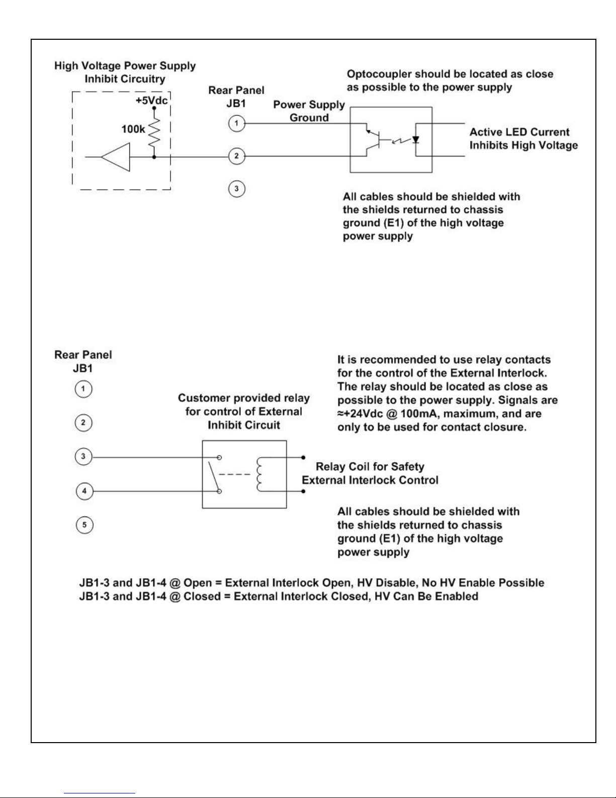
Figure 3.5 External Inhibit Interface Circuit
____________________________________________________________________________________
Figure 3.6 External Interlock Interface Circuit
ST/STR/STA MANUAL 13 118107-001 REV J
Page 21
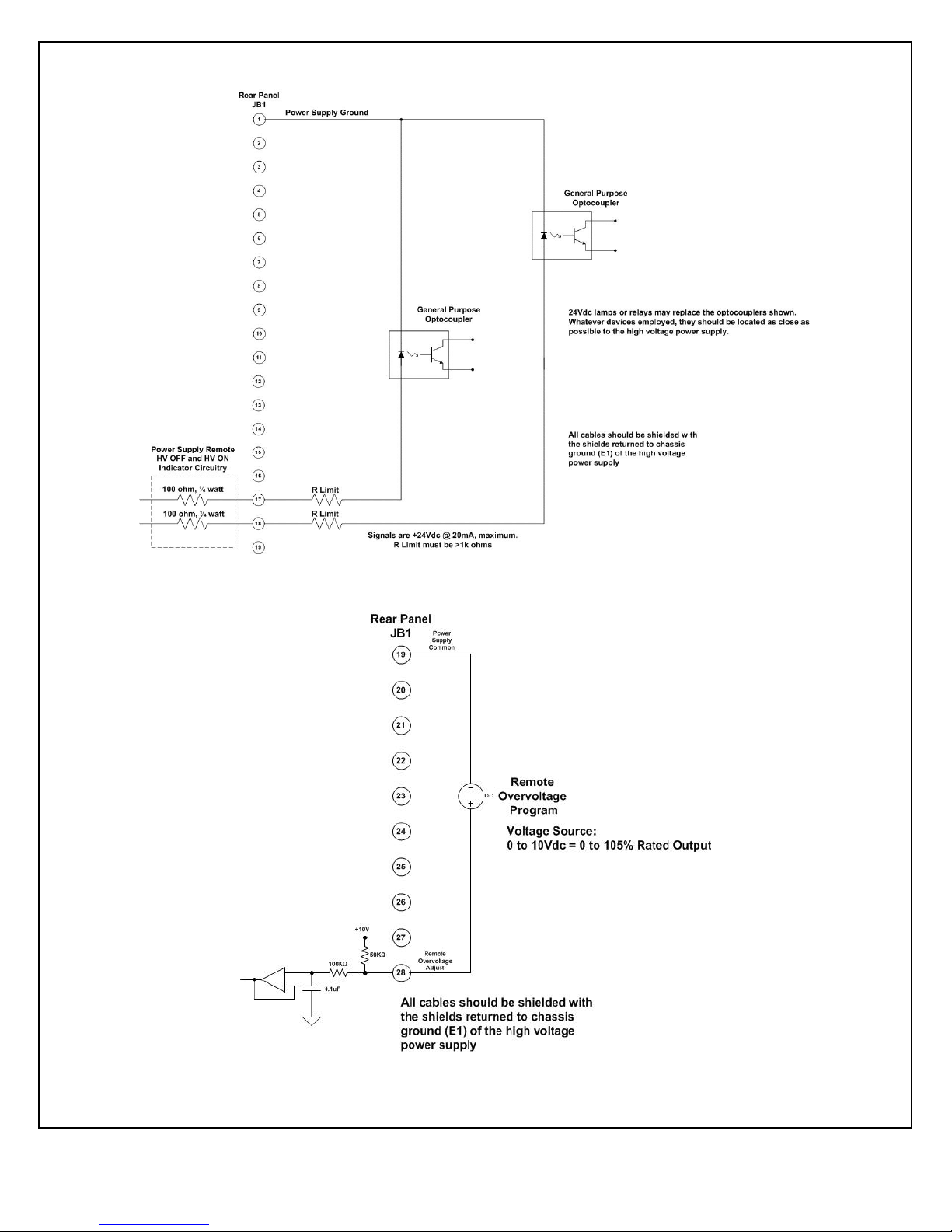
Figure 3.7 Remote High Voltage ON and Remote High Voltage OFF Indicator
Figure 3.8 Remote Overvoltage Adjust Interface
ST/STR/STA MANUAL 14 118107-001 REV J
Page 22
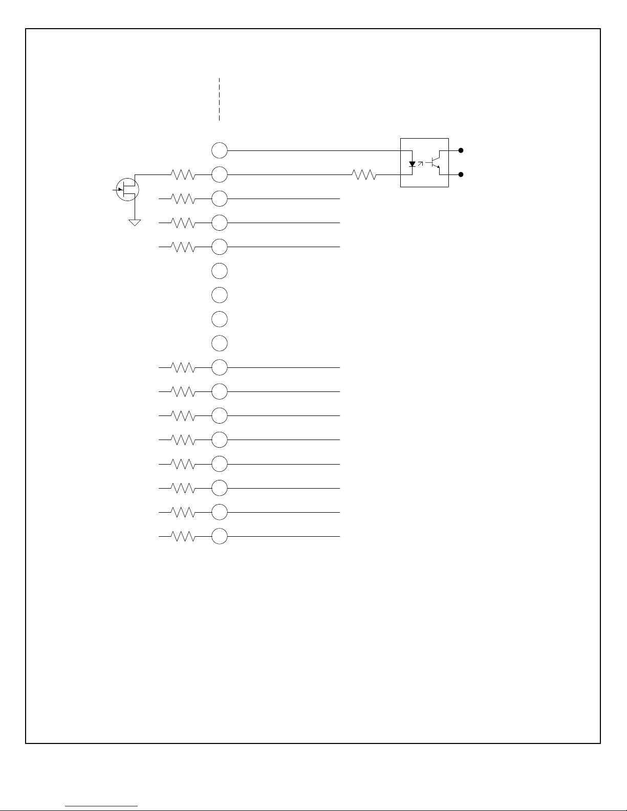
20
21
22
23
24
25
26
27
28
29
30
31
32
33
34
35
36
+24Vdc @ 100mA, maximum
Voltage Mode Status
Current Mode Status
Power Mode Status
Interlock Closed Status
Over Power Fault
Over Voltage Fault
Over Current Fault
System Fault
RGLT Error Fault
ARC
Over Temp Fault
AC Fault
General Purpose
Optocoupler
JB1 Rear Panel
100Ω
100Ω
100Ω
100Ω
100Ω
100Ω
100Ω
100Ω
100Ω
100Ω
100Ω
100Ω
R Limit
Signals are 35Vdc @ 10mA, maximum.
R Limit must be selected to limit current ≤ 10mA.
Power Supply
Internal Circuitry
Customer
External Circuitry
All cables should be shielded with the
shields returned to chassis ground (E1) of
the high voltage power supply.
24Vdc lamps or relays may replace the
optocouplers shown. Whatever devices
employed they should be located as close as
possible to the high voltage power supply.
Figure 3.9 Remote Status and Fault Indicator Interface
ST/STR/STA MANUAL 15 118107-001 REV J
Page 23
Pin
Signal
Parameters
1
Power Supply Common
Power Supply Ground
2
Reset/HV Inhibit
Toggle to reset latched faults, Ground = Inhibit, Open = HIGH VOLTAGE ON
3
External Interlock
+24Vdc @ open, <25mA @ closed
4
External Interlock Return
Return for External Interlock. Pins 3 and 4 must be connected to HV enable
5
mA Test Point
0-10Vdc = 0-100% rated output, Zout = 1kΩ, 1%
6
kV Test Point
0-10Vdc = 0-100% rated output, Zout = 1kΩ, 1%
7
+10Vdc Reference
+10Vdc @ 1mA
8
mA Program Input
0-10Vdc = 0-100% rated output, Zin =>10MΩ, jump to pin 8 for local control
9
Local mA Program Output
0-10Vdc = 0-100% rated output, front panel potentiometer
10
kV Program Input
0-10Vdc = 0-100% rated output, Zin =>10MΩ, jump to pin 11 for local control
11
Local kV Program Output
0-10Vdc = 0-100% rated output, front panel potentiometer
12
Remote Power On Output
24Vdc @ open, 2A peak, 1A DC @ closed
13
Remote Power On Return
Return for Remote Power On
14
Remote HV OFF
+24Vdc @ open, 2A peak, 1A DC @ closed, connect to pin 15 for front panel
operation
15
Remote HV OFF/ON Common
Remote HV OFF/ON Common
16
Remote HIGH VOLTAGE ON
+24Vdc @ open, 2A peak, 1A DC @ closed, momentarily connect to pin 15 for
HV enable
17
HIGH VOLTAGE OFFIndicator
+24Vdc @ 25mA = HV OFF
18
HIGH VOLTAGE ON Indicator
+24Vdc @ 25mA = HIGH VOLTAGE ON
19
Power Supply Common
Power Supply Ground
20
+24Vdc Output
+24Vdc @ 100mA, maximum
21
Voltage Mode Status
Open collector, Low = Active, 35V maximum @ 10mA
22
Current Mode Status
Open collector, Low = Active, 35V maximum @ 10mA
23
Power Mode Status
Open collector, Low = Active, 35V maximum @ 10mA
24
Interlock Closed Status
Open collector, Low = Active, 35V maximum @ 10mA
25
Power Test Point
0-10Vdc = 0-100% rated output, Zout = 5kΩ, 1%
26
Spare
27
Spare
28
Remote Overvoltage Adjust
0-10Vdc = 0-105% rated output
29
Over Power Fault
Open collector, Low = Active, 35V maximum @ 10mA
30
Over Voltage Fault
Open collector, Low = Active, 35V maximum @ 10mA
31
Over Current Fault
Open collector, Low = Active, 35V maximum @ 10mA
32
System Fault
Open collector, Low = Active, 35V maximum @ 10mA
33
RGLT Error Fault
Open collector, Low = Active, 35V maximum @ 10mA
34
ARC
Open collector, Low = Active, 35V maximum @ 10mA
35
Over Temp Fault
Open collector, Low = Active, 35V maximum @ 10mA
36
AC Fault
Open collector, Low = Active, 35V maximum @ 10mA
37
Spare
38
Spare
39
Spare
40
Spare
41
Spare
42
Remote Power Program Input
0-10Vdc = 0-100% rated output, Zout = 1kΩ, 1%, jump to pin 43 for local control
43
Local Power Program Output
0-10Vdc = 0-100% rated output, internal potentiometer
44
+5Vdc Output
+5Vdc @ 100mA, maximum
45
+15Vdc Output
+15Vdc @ 100mA, maximum
46
-15Vdc Output
-15Vdc @ 10mA, maximum
47
RS-232 Tx
RS-232 Tx
48
RS-232 Rx
RS-232 Rx
49
RS-232 GND
RS-232 GND
50
Power Supply Common
Power Supply Ground
= Denotes jumper connection for simplified local front panel control
Figure 3.10 JB1 Rear Panel Interface Connecter
ST/STR/STA MANUAL 16 118107-001 REV J
Page 24
Chapter 4
T
Principles of Operation
he ST series of high voltage power supplies utilizes
sophisticated power conversion technology. A variety
of analog, digital and power conversion techniques
are employed. This Principles of Operation will introduce
the basic function blocks that comprise the ST power
supply. For details on a specific circuit, consult
Spellman’s Engineering Department.
The ST power supply is an AC to DC converter. Within
the power supply, conversions of AC to DC, high
frequency AC, then to high voltage DC take place. By
reviewing functionality of the subassemblies, a basic
understanding of the process can be gained.
WARNING
THE ENERGY LEVELS USED AND GENERATED BY
THE POWER SUPPLY CAN BE LETHAL! DO NOT
ATTEMPT TO OPERATE THE POWER SUPPLY
UNLESS THE USER HAS A SUFFICIENT KNOWLEDGE
OF THE DANGERS AND HAZARDS OF WORKING
WITH HIGH VOLTAGE. DO NOT ATTEMPT TO
APPROACH OR TOUCH ANY INTERNAL OR
EXTERNAL CIRCUITS OR COMPONENTS THAT ARE
CONNECTED OR HAVE BEEN CONNECTED TO THE
POWER SUPPLY. BE CERTAIN TO DISCHARGE ANY
STORED ENERGY THAT MAY BE PRESENT BEFORE
AND AFTER THE POWER SUPPLY IS USED.
CONSULT IEEE RECOMMENDED PRACTICES FOR
SAFETY IN HIGH VOLTAGE TESTING #510-1983.
4.1 Line Rectification and
Filtering
WARNING
LINE VOLTAGE IS PRESENT WHENEVER THE
POWER SUPPLY IS CONNECTED TO THE INPUT LINE
VOLTAGE. BE SURE TO DISCONNECT THE LINE
CORD BEFORE OPENING THE UNIT. ALLOW 5
MINUTES FOR INTERNAL CAPACITANCE TO
DISCHARGE BEFORE TOUCHING ANYTHING
CONNECTED TO LINE REFERENCED CIRCUITRY
Simple three phase rectification provides the DC buss
voltage for the high frequency inverter.
An input line cord, three phase circuit breaker (customer
provided on 400Vac Option units), EMI Filter Assembly,
contactor, inrush bridge rectifier, electrolytic capacitors,
rail inductor and rail capacitor comprise the basic
components required for input line rectification.
The standard line input voltage for the ST Series is 180264Vac, 50/60Hz. An optional 360-528Vac, 50/60Hz
input voltage is available (400Vac Option). Optional
Single Phase input is available on the STR and STA. If
the user is unsure which input voltage is required, check
the serial tag on the rear of the power supply or consult
Spellman’s Sales Department
The customer provided AC power input is provided to the
unit via the four conductor AC line cord. Circuit
protection is provided by CB1, a fast acting magnetic trip
type circuit breaker. The load side of CB1 is connected to
EMI filter A2. The output of the EMI filter connects to
K1, a three phase contactor. K1 provides fail-safe type
disconnection of the line voltage to the power supply
rectification circuits. K1’s coil is controlled by a variety
of circuit conditions, which will be described later on.
The load side of CB1 is also connected to low voltage
power supply assembly A9, which provides various
voltages for housekeeping and control circuit power.
When contactor K1 is energized, voltage is applied to
isolated bridge rectifier power module CR1, used for line
voltage rectification. The output of CR1 is connected to
aluminum electrolytic capacitors C1 and C2 for line
filtering purposes. Capacitors C1 and C2 are initially
charged through inrush limiting charging resistors which
is located on POWER PWB – A6.
After an appropriate period of time to charge C1 and C2,
relays on POWER PWB – A6 are energized to short out
the inrush limiting resistors. The generated DC buss
voltage is supplied to the inverter circuitry through L2,
L3, L6 and L7. The inductors provide isolation for the
electrolytic capacitors C1 and C2, so the inverter’s high
frequency pulse currents are drawn from the metalized
film high frequency “rail capacitors” C3 and C12.
The POWER PWB – A6 provides the inrush limiting
function via R1, R2, R3 and R4. Relays K1 and K2 short
out the limiting resistors once the initial charging of C1
and C2 is complete. Resistors R7, R8, and R10, R11 form
two feedback divider circuits with terminating resistors
located on the SYSTEM CONTROL PWB – A1. These
impedance limited, low voltage + and – rail feedback
signals are monitored and if any abnormal conditions
appear, circuitry will shutdown the power supply.
ST/STR/STA MANUAL 17 118107-001 REV J
Page 25

Typically a SYSTEM FAULT and AC FAULT indication
will appear on the front panel if an error in the charging
circuits has occurred.
R5 on the POWER PWB – A6 functions as a bleeder
resistor, which is used to discharge the front end filter
capacitors C1 and C2. DS1 provides visual indication
when DC voltage is present. This indicator should not be
relied on for confirming the presence or absence of the
DC voltage in any situation where user safety is of
concern.
4.2 Inverter
The inverter employs a proprietary, quasi-resonant, pulse
width modulated topology. L1 and L5 are the resonating
inductors. Q1, Q2 Q3 and Q4 are high speed IGBT
isolated power modules. These devices provide high
frequency switching capability to control the flow of
current through the primary of the high voltage step up
transformers. The gate control for the switching devices
is provided by GATE DRIVE PWB A3 and A4. The
control signals are generated by the SYSTEM CONTROL
PWB – A1.
4.3 High Voltage Transformer
The output of the Inverter is connected to the primary of
the High Voltage Transformer. The High Voltage
Transformer is a step-up type. Typical secondary
voltages are in the range of 1kV to 4.5kV depending upon
the units specific maximum output voltage rating.
4.4 High Voltage Assembly
The High Voltage Assembly will vary depending upon
the model ordered. The circuitry typically consists of a
full wave, full bridge, or full wave doubler for voltage
outputs in the range of 1kV to 10kV. The higher voltage
ranges utilize various parallel, series arrangements of a
full wave voltage doubler. For example, the 8kV output
is obtained by connecting a number of full wave voltage
doublers in parallel. The 120kV output is obtained by
connecting a number of full wave voltage doublers in
series.
Output filtering is typically provided by an L-C type
filter. Voltage feedback for regulation and monitoring is
provided by a high bandwidth resistive/capacitive
compensated feedback divider. Current feedback for
regulation and monitoring is provided by a sense resistor
connected at the low voltage end of the High Voltage
output section.
4.5 System Control PWB
The majority of control circuits for power supply controls
are located on the SYSTEM CONTROL PWB – A1. For
trouble shooting and testing purposes, this board can be
easily accessed by removing the screws located on the
side panels near the front panel. The front panel will
hinge down allowing for easy access to the SYSTEM
CONTROL PWB
4.6 Front Panel Assembly
Front Panel CONTROL POWER, HV OFF, HIGH
VOLTAGE ON, switches, voltage and current
programming potentiometers, voltage and current digital
meters, and status indications are connected to the
FRONT PANEL PWB. – A7. The FRONT PANEL PWB
interfaces directly to the SYSTEM CONTROL PWB A1.
4.7 Master/Slave Rear Panel
PWB – ST Only
This assembly is only required and installed when more
than one ST chassis is configured in the system. By
configuring chassis in parallel using a Master/Slave
arrangements additional power increments of 12kW’s can
be obtained for each chassis added. This Master/Slave
Rear Panel PWB provided the necessary control signal
connectivity and functionality to operate multiple chassis
in parallel as a single high powered system.
ST/STR/STA MANUAL 18 118107-001 REV J
Page 26
T
Chapter 5
OPTIONS
He options available for this power supply are
described in this section. Options are specified by
including the option code in the model number as
described in Section 1.5.
5.1 Blank Front Panel BFP
The Blank Front Panel Option removes local control
functionality and metering from the standard front panel.
This is a popular cost saving measure for OEM
applications where the unit will only be controlled
remotely. The local front panel fault diagnostic panel is
retained providing comprehensive power supply
operational information.
5.2 High Stability HS
The standard internal voltage feedback divider is replaced
with a high precision voltage feedback divider providing a
50ppm/°C temperature coefficient.
5.3 High Voltage Cable Length
LL(X)
Custom length high voltage output cables, indicated in
foot measurement units. Various predetermined lengths
are available along with entirely custom lengths; contact
Spellman Sales Department for details.
5.4 360-528Vac Input 400VAC
This option factory configures the ST/STR to operate
from 360-528Vac, three phase, 50/60Hz input power.
5.5 180-264Vac Single Phase
Input (1PH)
This option factory configures STR and STA units to
operate from 180-264Vac, single phase, 50/60Hz input
power.
5.6 Custom Designed Models
X(#)
Units built to customer specifications are assigned an X
number by the factory. If this unit is an X model, a
specification control sheet is added at the end of this
instructional manual. Spellman welcomes the opportunity
to tailor units to fit your requirements or to develop new
products for your applications. Contact the Spellman
Sales Department with your need.
ST/STR/STA MANUAL 19 118107-001 REV J
Page 27

5.7 Parallel Option Units
(Multiple Chassis Systems – ST
only)
Physically install the units in a cabinet or stack them one
on top the other, typically the Master units is located at
the top to ease access to the local controls on the full
featured front panel. Cabling up the system is similar
regardless of the numbers of Slave chassis. The following
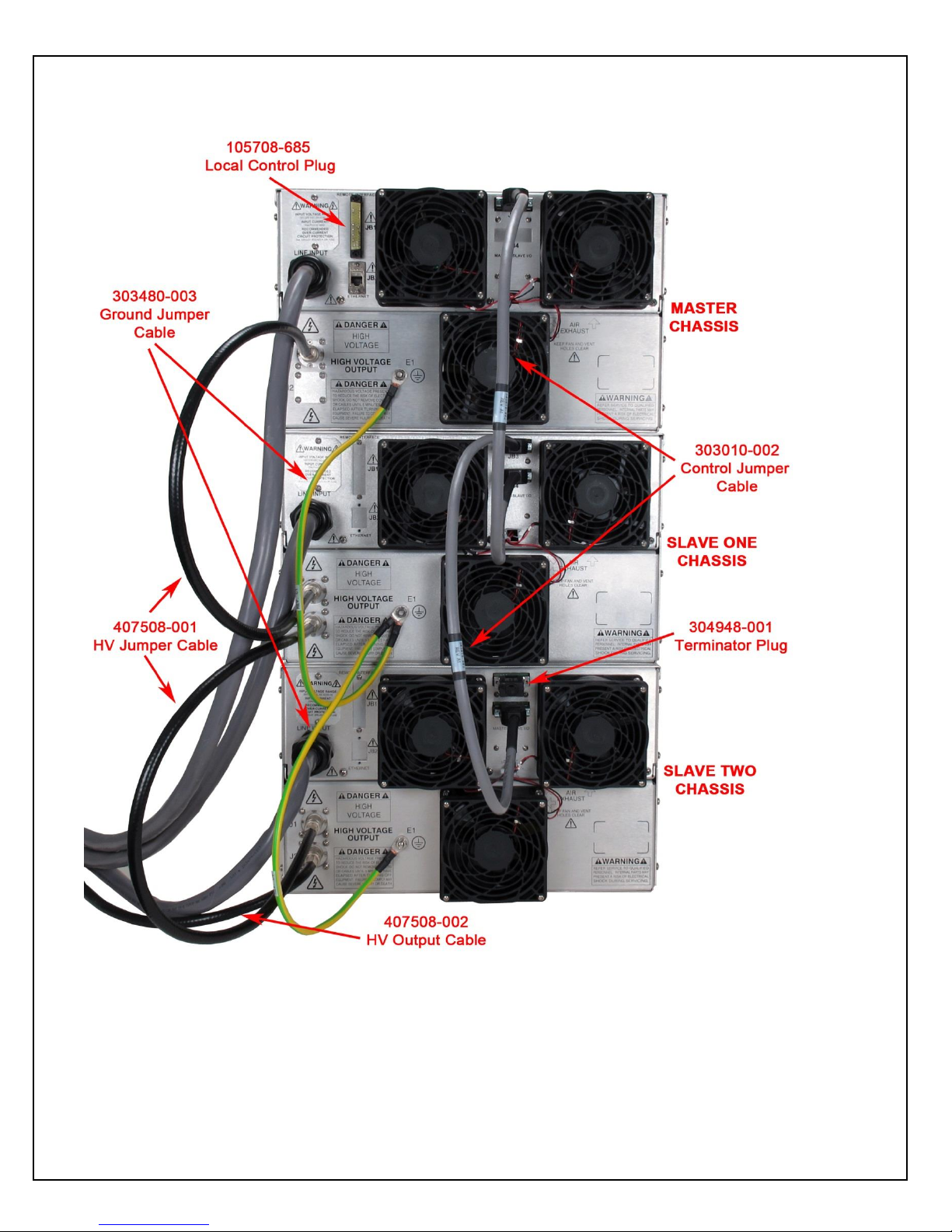
items will be required to connect up each parallel option
unit:
Control Jumper Cable (gray cable, 15 pin D connecters on
each end)
Ground Jumper Cable (green/yellow cable, ring lugs on
each end)
High Voltage Jumper Cable (black cable, HV connecter
on each end)
Terminator Plug (black plastic clam shell, 15 pin D
connecter)
One cable of each type is required for each Slave chassis;
only one terminator plug is required for each system. The
connections are as follows; repeat as needed for additional
Slave Chassis:
Control Jumper Cable – Connect one side to JB3 of the
Master chassis, connect the other side to JB4 of the Slave
Chassis.
Ground Jumper Cable – Connect one side to E1 ground
stud on the Master chassis, connect the other side to E1
ground stud of the Slave chassis. ***Connect the
customer provided “System Ground Cable” and the
customer provided “Load Return Cable” to the E1 ground
stud on the back of the Master Chassis. Please see Typical
Operating Setup ST figure for required ground
connections***
High Voltage Jumper Cable – Connect one side to J1 of
the Master chassis; connect the other side to J1 of the
Slave Chassis. Connect the terminated side of the High
voltage output cable to J2 of the Slave chassis; connect
the unterminated side to the load as applicable.
Terminator Plug– Plug the Terminator Plug into JB3 of
the Slave Chassis.
The instructions above are for a two chassis Master/Slave
unit, but these instructions can be used for systems with
any number of Slave units keeping these two points in
mind:
●The High Voltage Output Cable always exists from the
“last” Slave unit
●The Terminator Plug is always connected to the JB3
connecter of the “last” Slave unit.
See the annotated photograph of the wiring connections
for a 3 chassis system (Master/Slave1/Slave2) that
follows these instructions.
Cooling Note:
For proper cooling, and to maximize product life span, a
minimum of 1U (1.75”) rack space should be provided
above and below each chassis, and between chassis of
multi-chassis systems. This will allow air circulation, and
also reduce heating effects on other equipment in the
cabinet.
ST/STR/STA MANUAL 20 118107-001 REV J
Page 28
ST/STR/STA MANUAL 21 118107-001 REV J
Page 29
Chapter 6
T
WARNING
WARNING
MAINTENANCE
his section describes periodic servicing and
performance testing procedures.
THIS POWER SUPPLY GENERATES VOLTAGES
THAT ARE DANGEROUS AND MAY BE FATAL.
OBSERVE EXTREME CAUTION WHEN WORKING
WITH HIGH VOLTAGE.
6.1 Periodic Servicing
Approximately once a year (more often in high dust
environments), disconnect the power to the unit and
remove the top cover. Use compressed air to blow dust
out of the inside of the unit. Avoid touching or handling
the high voltage assembly. Be sure that the fan is not
obstructed and spins freely. The fan has sealed bearings
and does not need lubrication. Be sure to replace the
cover before operating for proper cooling.
Turn the chassis over and remove the bottom cover. Use
compressed air to blow dust out. NOTE: On 10kV and
below, an air insulated high voltage section is used.
Avoid touching or handling the high voltage assembly.
Be sure to replace the bottom cover before operating the
unit.
High voltage test procedures are described in Bulletin
STP-783, available by clicking the following link
Standard Test Procedures for High Voltage Power
Supplies. Test equipment, including an oscilloscope, a
high impedance voltmeter, and a high voltage divider
(such as the Spellman HVD-100) is needed for
performance tests. All test components must be rated for
applicable operating voltage.
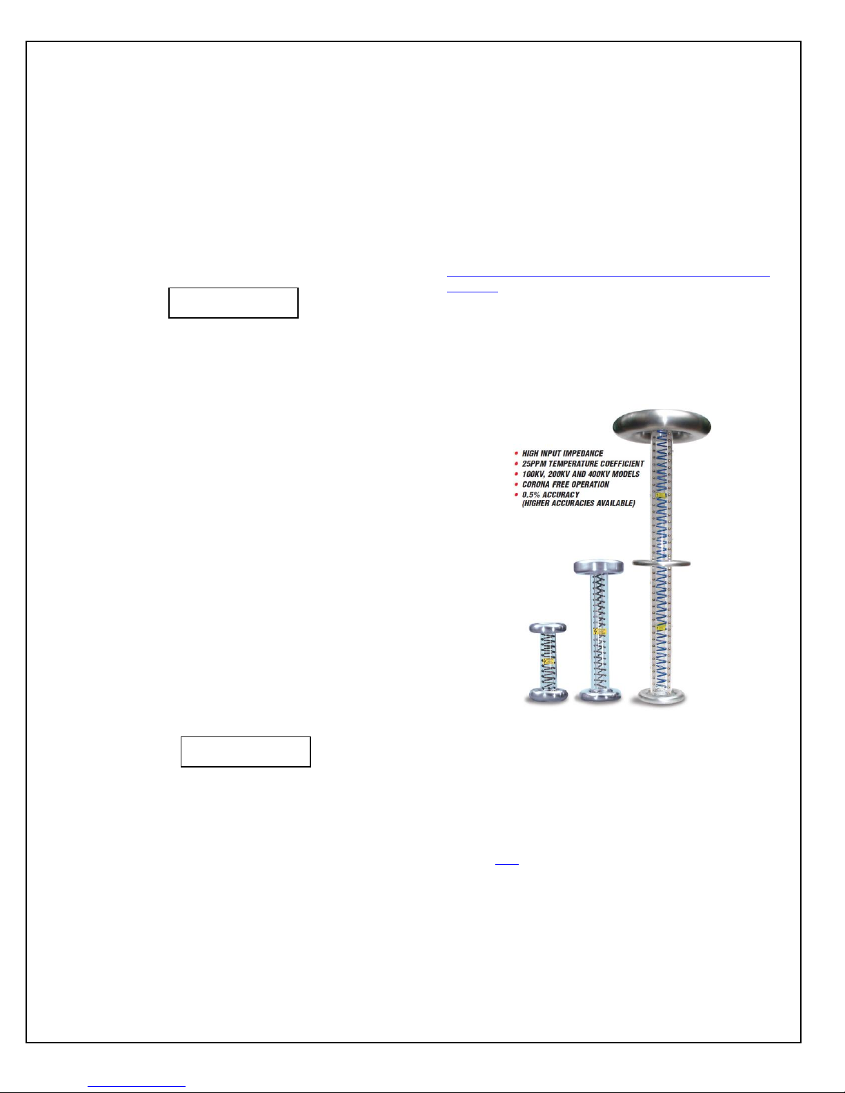
6.3 High Voltage Dividers
6.2 Performance Test
HIGH VOLTAGE IS DANGEROUS. ONLY
QUALIFIED PERSONNEL SHOULD PERFORM
THESE TESTS.
ST/STR/STA MANUAL 22 118107-001 REV J
High voltage dividers for precise measurements of output
voltage with accuracy up to 0.1% are available from
Spellman. The HVD-100 is used for voltages up to
100kV, the HVD-200 measures up to 200kV and the
HVD-400 measures up to 400kV. The Spellman HVD
divider is designed for use with differential voltmeters or
high impedance digital voltmeters. The data sheet for
Spellman’s series of HVD dividers can be viewed by
clicking here.
Page 30

Chapter 7
C
REPLACEMENT PARTS
7.1 Replacement Parts
ontact the Spellman Customer Service Department
for parts lists for specific models.
Spellman provides parts and subassemblies for its high
voltage power supplies but recommends that only
qualified personnel perform repairs. High voltage is
dangerous; even minor mistakes in repairs can have
serious consequences.
When requesting parts, please provide the complete
model number and serial number of the power supply in
question.
7.2 Correspondence and
Ordering Spare Parts
Each Spellman power supply has an identification label
on the rear of the chassis that bears its model and serial
number.
When requesting engineering or applications information,
please state the model and serial number of the power
supply. If specific components or circuit sections are
involved in the inquiry, it is helpful to indicate the
component symbol number(s) shown on the applicable
schematic diagram.
When ordering spare parts, please specify the part’s
description, the part’s reference designation or part
number, and the model and serial number of the unit.
ST/STR/STA MANUAL 23 118107-001 REV J
Page 31

Chapter 8
FACTORY SERVICE
8.1 Warranty Repairs
During the Warranty period, Spellman will repair all units
free of charge. The Warranty is void if the unit is worked
on by other than Spellman personnel. See the Warranty
in the rear of this manual for more information. Follow
the return procedures described in Section 8.2. The
customer shall pay for shipping to and from Spellman.
8.2 Factory Service Procedures
Spellman has a well-equipped factory repair department.
If a unit is returned to the factory for calibration or repair,
a detailed description of the specific problem should be
attached.
For all units returned for repair, please obtain an
authorization to ship from the Customer Service
Department, either by phone or mail prior to shipping.
When you call, please state the model and serial numbers,
which are on the plate on the rear of the power supply,
and the purchase order number for the repair. A Return
Material Authorization Code Number (RMA Number) is
needed for all returns. This RMA Number should be
marked clearly on the outside of the shipping container.
Packages received without an RMA Number will be
returned to the customer. The Customer shall pay for
shipping to and from Spellman.
A preliminary estimate for repairs will be given by phone
by Customer Service. A purchase order for this amount is
requested upon issuance of the RMA Number. A more
detailed estimate will be made when the power supply is
received at the Spellman Repair Center. In the event that
repair work is extensive, Spellman will call to seek
additional authorization from your company before
completing the repairs.
8.3 Ordering Options and
Modifications
Many of the options listed in Chapter 5 can be retrofitted
into Spellman power supplies by our factory. For prices
and arrangements, contact our Sales Department.
8.4 Shipping Instructions
All power supplies returned to Spellman must be sent
shipping prepaid. Pack the units carefully and securely in
a suitable container, preferably in the original container, if
available. The power supply should be surrounded by at
least four inches of shock absorbing material. Please
return all associated materials, i.e. high voltage output
cables, interconnection cables, etc., so that we can
examine and test the entire system.
All correspondence and phone calls should be directed to:
Spellman High Voltage Electronics Corp.
475 Wireless Boulevard
Hauppauge, New York 11788
TEL: (631) 630-3000 FAX: (631) 435-1620
E-Mail: sales@Spellmanhv.com
www.spellmanhv.com
ST/STR/STA MANUAL 24 118107-001 REV H
Page 32

To obtain information on Spellman’s product warranty please visit our website at:
http://www.spellmanhv.com/en/About/Warranty.aspx
Page 33

Table Of Contents
1.0 Scope ....................................................................................................................... 3
2.0 Functional Description ........................................................................................... 3
3.0 Getting Started - Interface Wiring and Pin-outs ................................................... 3
3.1 RS-232 Interface ................................................................................................................... 3
3.2 Ethernet Interface .................................................................................................................. 4
3.3 RS-232 Cabling ..................................................................................................................... 5
3.4 Ethernet Cabling ................................................................................................................... 6
4.0 Getting Started - Software ...................................................................................... 7
4.1 RS-232 .................................................................................................................................. 7
4.2 Ethernet ................................................................................................................................. 8
5.0 Ethernet Commands ............................................................................................. 14
5.1 TCP/IP Format .................................................................................................................... 14
5.2 Command Arguments ......................................................................................................... 15
5.3 Command Overview ........................................................................................................... 15
5.4 Response Overview ............................................................................................................ 15
5.5 Command Structure ............................................................................................................ 17
6.0 Serial Commands – RS-232 .................................................................................. 35
6.1 Serial Interface Protocol ..................................................................................................... 35
6.2 Command Arguments ......................................................................................................... 35
6.3 Checksums .......................................................................................................................... 35
6.4 Command Overview ........................................................................................................... 38
6.5 Response Overview ............................................................................................................ 38
6.6 Command Structure ............................................................................................................ 39
6.7 Spellman Test Commands .................................................................................................. 58
6.8 Serial Command Handling .................................................................................................. 58
7.0 Error Codes ........................................................................................................... 59
101501-565 Rev C Page 2 of 58
Page 34

WARNING
THIS EQUIPMENT GENERATES DANGEROUS VOLTAGES THAT MAY BE FATAL.
PROPER GROUNDING OF ALL HIGH VOLTAGE EQUIPMENT IS ESSENTIAL.SEE ST
OWNERS MANUAL FOR PROPER GROUNDING TECHNIQUE AND SAFETY
PRECAUTIONS BEFORE APPLING AC INPUT POWER TO THE ST UNIT.
TO PREVENT DAMAGE TO THE HOST COMPUTER THE COMPUTER SHOULD BE
GROUNDED TO THE SAME GROUND AS THE UUT.
1.0 SCOPE
This document applies to the communications interfaces on the ST, assembly
460231.
2.0 FUNCTIONAL DESCRIPTION
The ST provides 3 different types of digital communications interfaces:
DB-50F Digital Breakout on JB1
Ethernet (10/100-Base-T) on JB9
3.0 GETTING STARTED - INTERFACE WIRING AND PIN-OUTS
3.1 RS-232 INTERFACE
The RS-232 interface has the following attributes:
115.2K bits per second
No Parity
8 Data Bits
1 Stop Bit
No handshaking
Included in DB-50F Digital Breakout
The pinout of the DB-50F connector is:
101501-565 Rev C Page 3 of 58
Page 35

Pin Signal Parameters
1 Power Supply Common Power Supply Ground
2 Reset/HV Inhibit Toggle to reset latched faults, Ground = Inhibit, Open = HV ON
3 External Interlock +24Vdc @ open, <25mA @ closed
4 External Interlock Return Return for External Interlock. Pins 3 and 4 must be connected to HV enable
5 mA Test Point 0-10Vdc = 0-100% rated output, Zout = 1kΩ, 1%
6 kV Test Point 0-10Vdc = 0-100% rated output, Zout = 1kΩ, 1%
7 +10Vdc Reference +10Vdc @ 1mA
8 mA Program Input 0-10Vdc = 0-100% rated output, Zin =>10MΩ, jump to pin 8 for local control
9 Local mA Program Output 0-10Vdc = 0-100% rated output, front panel potentiometer
10 kV Program Input 0-10Vdc = 0-100% rated output, Zin =>10MΩ, jump to pin 11 for local control
11 Local kV Program Output 0-10Vdc = 0-100% rated output, front panel potentiometer
12 Remote Power On Output 24Vdc @ open, <25mA @ closed
13 Remote Power On Return Return for Remote Power On
14 Remote HV OFF +24Vdc @ open, <25mA @ closed, connect to pin 15 for front panel operation
15 Remote HV OFF/ON Common Remote HV OFF/ON Common
16 Remote HV ON +24Vdc @ open, <25mA @ closed, momentarily connect to pin 15 for HV enable
17 HV OFF Indicator +24Vdc @ 25mA = HV OFF
18 HV ON Indicator +24Vdc @ 25mA = HV ON
19 Power Supply Common Power Supply Ground
20 +24Vdc Output +24Vdc @ 100mA, maximum
21 Voltage Mode Status Open collector, Low = Active, 35V maximum @ 10mA
22 Current Mode Status Open collector, Low = Active, 35V maximum @ 10mA
23 Power Mode Status Open collector, Low = Active, 35V maximum @ 10mA
24 Interlock Closed Status Open collector, Low = Active, 35V maximum @ 10mA
25 Power Test Point 0-10Vdc = 0-100% rated output, Zout = 5kΩ, 1%
26 Spare
27 Spare
28 Remote Overvoltage Adjust 0-10Vdc = 0-105% rated output
29 Over Power Fault Open collector, Low = Active, 35V maximum @ 10mA
30 Over Voltage Fault Open collector, Low = Active, 35V maximum @ 10mA
31 Over Current Fault Open collector, Low = Active, 35V maximum @ 10mA
32 System Fault Open collector, Low = Active, 35V maximum @ 10mA
33 RGLT Error Fault Open collector, Low = Active, 35V maximum @ 10mA
34 ARC Open collector, Low = Active, 35V maximum @ 10mA
35 Over Temp Fault Open collector, Low = Active, 35V maximum @ 10mA
36 AC Fault Open collector, Low = Active, 35V maximum @ 10mA
37 Spare
38 Spare
39 Spare
40 Spare
41 Spare
42 Remote Power Program Input 0-10Vdc = 0-100% rated output, Zout = 1kΩ, 1%, jump to pin 43 for local control
43 Local Power Program Output 0-10Vdc = 0-100% rated output, internal potentiometer
44 +5Vdc Output +5Vdc @ 100mA, maximum
45 +15Vdc Output +15Vdc @ 100mA, maximum
46 -15Vdc Output -15Vdc @ 10mA, maximum
47 RS-232 Tx RS-232 Tx
48 RS-232 Rx RS-232 Rx
49 RS-232 GND RS-232 GND
50 Power Supply Common Power Supply Ground
The necessary connections for the RS-232 interface are on pins 47, 48 and 49.
3.2 ETHERNET INTERFACE
The Ethernet interface has the following attributes:
10/100-Base-T
IP address can be set by the system integrator (Default Address:
192.168.1.4)
Network Mask can be set by the system integrator (Default Mask:
255.255.255.0)
TCP Port Number can be set by the system integrator (Default Port:
50000)
101501-565 Rev C Page 4 of 58
Page 36

RJ-45 connector
Network attachment via Crossover and Standard Ethernet cables.
Supported Operating Systems: Windows 98 2ED, Windows 2000
(SP2), Windows NT (SP6), Windows XP Professional
LED 1 LED 2
8 7 6 5 4 3 2 1
Figure 2 – JB9, Ethernet RJ45 Jack (front view)
PIN DESCRIPTION
1 TX+
2 TX3 RX+
4 5 6 RX7 8 -
The Ethernet RJ-45 has two LED indicators, as shown in Figure 2. The left
LED, LED1 indicates that the network processor has a valid network link.
The right LED, LED2 indicates network activity.
3.3 RS-232 CABLING
A shielded cable is used to connect the ST serial port through the 50 pin
breakout to the serial port on a standard personal computer. Please refer
to the following chart.
PC Connector (DB-9 Female) ST Connector (DB-50 male)
Pin 2: TX from ST to PC Pin 47: TX from ST to PC
Pin 3: RX to ST from PC Pin 48: RX to ST from PC
Pin 5: Ground Pin 49: Ground
3.4 ETHERNET CABLING
Shielded Category 5 (CAT5) Ethernet patch cables are used to connect
the ST to the host computer. There are two ways to connect to the ST
101501-565 Rev C Page 5 of 58
PC to ST Board Cable Details
Page 37

board via Ethernet: the first is to directly cable between the host and the
ST board, and the second is through the use of a switch, hub, or network.
A direct connection requires a non-standard cable where the wires are not
run straight through. Please refer to the two cable ends shown below in
figure 4.
Figure 4 – Crossover Cable for Direct Connection
A standard connection through a hub, switch, or network uses a standard
CAT5 patch cable. Please refer to the two cable ends shown below in
figure 5
Figure 5 – Standard Straight Through Cable – Standard CAT5 Patch
4.0 GETTING STARTED – SOFTWARE
The following sections detail how to create software to interface to the ST
communications interfaces.
101501-565 Rev C Page 6 of 58
Page 38

4.1 RS-232
The RS-232 interface makes use of a standard ‘command/response’
communications protocol. See section 6.0 for the syntax of the serial
interface protocol.
All software that addresses the RS-232 interface must adhere to the
following parameters:
A Baud rate of 115.2K bps
No Parity
8 Data Bits
1 Stop Bit
No handshaking
4.1.1 Enabling Communications Objects in Visual Basic for RS-232
Communications in Microsoft Visual Basic 6.0 are directed to a control
that abstracts the port. In the case of serial we need Microsoft Comm
Control 6.0. To enable this in your VB 6 project, go to:
Project -> Components
Then in the list make sure that Microsoft Comm Control 6.0 has a
check next to it. The Comm Control Object should then appear in your
toolbox. It will have an icon of a telephone and will be named:
MSComm. This can be dragged and dropped into your application.
You will then need to set the object’s properties.
4.1.2 Configuring Communications in Visual Basic for RS-232
In order to configure the MSComm Object, first you must initialize it
in the Object properties:
Settings 115200,n,8,1
Handshaking 0 – comNone
The application can be set to either default to a specific COM Port
or the End User can be allowed to choose one for the particular PC.
For the “Default” scenario, include the following commands in the
Form_Load() routine:
MSComm1.CommPort = portNumber
MSComm1.PortOpen = True
For the “Choice” scenario, place the above two commands in a
selectable menu item.
101501-565 Rev C Page 7 of 58
Page 39

4.2 ETHERNET
The ST contains an embedded diagnostic web server that can be
accessed through any standard web browser by browsing to the ST’s IP
address. For example:
http://192.168.1.4
The Ethernet interface communicates using the following protocols:
TCP/IP
HTTP
TFTP
FTP
4.2.1 Direct Connection between the ST and a Computer
A direct Ethernet connection between the ST and the computer
requires an RJ45 crossover cable. The end connectors will look
identical to a “normal” RJ45 connector but the colors of some of the
wires in the connectors will be “reversed”. Hold up the two ends of
the RJ45 cable and look at the color of the wires from left to right.
They should differ on the two connectors. Please see figure 4 on
rage 7 for reference.
When direct connecting the ST to a computer using a crossover
cable over Ethernet they are essentially participating in a private
network. As such you need to pick two valid IP addresses, one for
each device.
The table below illustrates that not all IP addresses are actually
valid IP addresses. For example, IP addresses beginning with 127
are not valid.
Class Address Range
A 1.0.0.0-126.255.255.255
B 128.0.0.0-191.255.255.255
C 192.0.0.0-223.255.255.255
4.2.2.1 Configuring the Computer for Direct Ethernet
Connection
As mentioned above both the IP Address and Subnet Mask need to
be configured. In our environment computers normally are assigned
IP addresses dynamically, using DHCP. We need to change this
and assign the IP Address statically to the one we have selected.
101501-565 Rev C Page 8 of 58
Page 40

Here are the steps on Windows XP. On the desktop right click on
“My Network Places” and select properties at the bottom of the
menu.
Figure 16 – Right Click on Desktop
Figure 17 – Select Properties
After selecting properties you are brought up to the screen below
(Figure 18). You must RIGHT CLICK and select Properties on
Local Area Connection, and not double click which will display a
window similar to figure 19.
Figure 18 – Here you must Right Click and Select Properties
101501-565 Rev C Page 9 of 58
Page 41

Figure 19 – Local Area Connection Properties
Now you must select “Internet Protocol (TCP/IP)” and click on the
Properties button to be brought to figure 20. Lastly you must
disable any firewall software you have running. If you are running a
proxy server for Internet access, you must also disable the proxy
client. Disabling this also requires a reboot.
101501-565 Rev C Page 10 of 58
Page 42

Figure 20 – TCP/IP Properties
4.2.2.2 Testing a Direct Connection
You can use the program “Ping” to test a network connection
between the computer and the ST. “Ping” is a command line tool so
we will need to bring up a command prompt. Under Windows NT,
2000 and XP the name of this command is “CMD”. Under Windows
98 the name of this command is “Command”.
To do this, click on Start->Run->Cmd
Then on the command line type
Ping <IP Address>
For example
Ping 192.168.1.4
If the ST is found at the specified IP address, the Ping command
will respond with a report that is similar to:
101501-565 Rev C Page 11 of 58
Page 43

Pinging 192.168.1.4 with 32 bytes of data:
Reply from 192.168.1.4: bytes=32 time<1ms TTL=64
Reply from 192.168.1.4: bytes=32 time<1ms TTL=64
Reply from 192.168.1.4: bytes=32 time<1ms TTL=64
Reply from 192.168.1.4: bytes=32 time<1ms TTL=64
Ping statistics for 192.168.1.4:
Packets: Sent = 4, Received = 4, Lost = 0 (0% loss),
Approximate round trip times in milli-seconds:
Minimum = 0ms, Maximum = 0ms, Average = 0ms
4.2.3 Configuring the ST For a Local Area Network (LAN)
If you have chosen to place the ST onto your local area network
you will need:
A CAT5 network patch cable to physically connect the ST to
the LAN
A static IP address to assign to the ST.
Remember that even if the IP address you have selected is in
general a valid IP address it needs to be valid for your LAN (local
area network). Otherwise the device will not be accessible from an
Internet browser or Ping.
4.2.4 Enabling Communications Objects in Visual Basic for Ethernet
Communications
For Ethernet communications, we need Microsoft Winsock Control 6.0 and
SP5. To enable this in your VB 6 project, go to:
Project -> Components
Once selected in your toolbox you will have an icon of two computers
linked together and it will be named: Winsock.This can be dragged and
dropped into your application. Then set the object’s properties.
4.2.5 Configuring Communications in Visual Basic for Ethernet
In order to configure the Winsock Object, you must make the following
initialization in the object’s properties:
Protocol 0 – sckTCPProtocol
Then, in the application code, include the following commands:
101501-565 Rev C Page 12 of 58
Page 44

tcpClient.RemoteHost = host
tcpClient.RemotePort = portNumber
tcpClient.Connect
For further information regarding the use of the above commands, please
refer to your Visual Studio Help File.
4.2.5.1 Data Output Example
MSComm1 is the serial port and TcpClient is the
Ethernet port.
If (portType = "ethernet") Then
tcpClient.SendData (str)
Else
MSComm1.InBufferCount = 0
On Error GoTo done
MSComm1.Output = str
done:
tmrOpenClose.Enabled = True
End If
4.2.5.2 Data Input Example
If (portType = "ethernet") Then
Do
DoEvents
tcpClient.GetData temp$
str = str + temp$
Loop Until InStr(str, Chr(3)) Or Timer - t1 > 1
On Error Resume Next
Else
Do
DoEvents
If MSComm1.InBufferCount > 0 Then
str = str & MSComm1.Input
End If
Loop Until InStr(str, Chr(3)) Or Timer - t1 > 1
If InStr(str, Chr(3)) > 0 Then
tmrOpenClose.Enabled = False
End If
End If
101501-565 Rev C Page 13 of 58
Page 45

5.0 ETHERNET COMMANDS
5.1 TCP/IP FORMAT
Each Ethernet command will consist of a TCP/IP header followed by the required
data bytes. Figure 27 summarizes the TCP/IP header configuration. Please note
that this functionality is provided by the software implementation of the Open
Systems Interconnection (OSI) TCP/IP protocol stack, specifically the upper 4
layers.
Byte
0 Protocol
Version
Header
Length
4 Packet ID Flags Fragmentation Offset
Type Of
Service
Total Length
8 Time To Live
Protocol Header checksum
12 Source Address
16 Destination Address
20 Source Port
Destination Port
24 Sequence Number
28 Acknowledgement Number
32 Data
Offset
36 Checksum
40 Data Byte 1
Reserved Code Bits
Data Byte 2 Data Byte 3 Data Byte N
Window
Urgent Pointer
Figure 24: Network TCP/IP datagram header
101501-565 Rev C Page 14 of 58
Page 46

The format of Data Bytes 1 through N are as follows:
<STX><CMD><,>ARG><,><ETX>
Where:
<STX> = 1 ASCII 0x02 Start of Text character
<CMD> = 2 ASCII characters representing the command ID
<,> = 1 ASCII 0x2C character
<ARG> = Command Argument
<,> = 1 ASCII 0x2C character
<ETX> = 1 ASCII 0x03 End of Text character
5.2 COMMAND ARGUMENTS
The format of the numbers is a variable length string. To represent the number
42, the string ‘42’, ‘042’, or ‘0042’ can be used. This being the case, commands
and responses that carry data are variable in length.
5.3 COMMAND OVERVIEW
TCP/IP Command Overview
Command Name <CMD> <ARG> RANGE
Program User Configurations 9 See Desc. See Desc.
Program kV Setpoint 10 1-4 ASCII 0-4095
Program mA Setpoint 11 1-4 ASCII 0-4095
Request kV Setpoint 14 None -
Request mA Setpoint 15 None -
Request Misc. Analog
Monitor Readbacks
20 None -
Request Status 22 None -
Request Software Version 23 None -
Request Model Number 26 None -
Request User Configs 27 None -
Request Unit Scaling 28 None -
Request FPGA Version 43 None -
Request kV monitor 60 None -
Request mA monitor 61 None -
Request Slave Faults 68 None -
Request System Voltages 69 None -
Reset Faults 74 None -
Program Local/Remote Mode 99 1 ASCII 0 or 1
5.4 RESPONSE OVERVIEW
The command responses will follow the same network TCP/IP header format as
outlined above in section 5.1. This list is comprised of Commands with complex
101501-565 Rev C Page 15 of 58
Page 47

responses only. Commands using a simple response will use the <$> character
(ASCII 0x24) as a “Success” response or a single character error code. These
will be seven ASCII characters in length.
Response Name <CMD> Response
Request kV Setpoint 14 10 ASCII
Request mA Setpoint 15 10 ASCII
Request Misc. Analog Readbacks 20 21 – 45 ASCII
Request Status 22 37 ASCII
Request Software Version 23 22 ASCII
Request Model Number 26 7 – 21 ASCII
Request User Configs 27 9 – 17 ASCII
Request Unit Scaling 28 9 – 14 ASCII
Request FPGA Version 43 22 ASCII
Request kV monitor 60 7 – 10 ASCII
Request mA monitor 61 7 – 10 ASCII
Request Slave Faults 68 31 ASCII
Request System Voltages 69 45 ASCII
101501-565 Rev C Page 16 of 58
Page 48

5.5 COMMAND STRUCTURE
5.5.1 Program User Configurations
Description:
The host requests that the firmware set the kV and mA ramp rates.
Direction:
Host to supply
Syntax:
<STX><09><,><ARG1><,><ARG2><,><ETX>
Where:
<ARG1> = kV Rate Ramp
<ARG2> = mA Rate Ramp
<ARG3> = AOL Enable
<ARG4> = APT Enable
Range:
Valid values for ARG1 and ARG2 are from 0 through 10000 milliseconds.
In 10 milliseconds increments. For ARG3 and ARG4 they are 0 (disabled)
and 1 (enabled).
Response:
If an error is detected, the Power Supply responds with:
<STX>09,!,<ERROR>,<ETX>
Please reference the Error Code section for a list of valid error codes.
If the message is accepted, the Power Supply responds with:
<STX>09,$,<ETX>
Example:
Set kV and mA to a 10 ms ramp, with AOL and APT disabled.
<STX>09,10,10,0,0,<ETX>
101501-565 Rev C Page 17 of 58
Page 49

5.5.2 Program kV
Description:
The host requests that the firmware change the kV setpoint.
Direction:
Host to supply
Syntax:
<STX><10><,><ARG><,><ETX>
Where:
<ARG> = 0 - 4095 in ASCII format
Response:
If an error is detected, the Power Supply responds with:
<STX>10,!,<ERROR>,<ETX>
Please reference the Error Code section for a list of valid error codes.
If the message is accepted, the Power Supply responds with:
<STX>10,$, <ETX>
Example:
Set kV to the full scale voltage.
<STX>10,4095,<ETX>
101501-565 Rev C Page 18 of 58
Page 50

5.5.3 Program mA
Description:
The host requests that the firmware change the mA setpoint.
Direction:
Host to supply
Syntax:
<STX><11><,><ARG><,><ETX>
Where:
<ARG> = 0 - 4095 in ASCII format
Response:
If an error is detected, the Power Supply responds with:
<STX>11,!,<ERROR>,<ETX>
Please reference the Error Code section for a list of valid error codes.
If the message is accepted, the Power Supply responds with:
<STX>11,$,<ETX>
Example:
Set mA to the full scale current.
<STX>11,4095,<ETX>
101501-565 Rev C Page 19 of 58
Page 51

5.5.4 Request kV Setpoint
Description:
The host requests that the firmware report the kV setpoint.
Direction:
Host to supply
Syntax:
<STX><14><,><ETX>
Response:
If an error is detected, the Power Supply responds with:
<STX>14,!,<ERROR>,<ETX>
Please reference the Error Code section for a list of valid error codes..
If the message is accepted, the Power Supply responds with:
<STX>14,<ARG>,<ETX>
Where:
<ARG> = 0 - 4095 in ASCII format
Example Response:
KV setpoint is set to full scale.
<STX>14,4095,<ETX>
101501-565 Rev C Page 20 of 58
Page 52

5.5.5 Request mA Setpoint
Description:
The host requests that the firmware report the current mA setpoint.
Direction:
Host to supply
Syntax:
<STX><15><,><ETX>
Response:
If an error is detected, the Power Supply responds with:
<STX>15,!,<ERROR>,<ETX>
Please reference the Error Code section for a list of valid error codes.
If the message is accepted, the Power Supply responds with:
<STX>15,<ARG>,<ETX>
Where:
<ARG> = 0 - 4095 in ASCII format
Example Response:
MA setpoint is set to full scale.
<STX>15,4095,<ETX>
101501-565 Rev C Page 21 of 58
Page 53

5.5.6 Request Miscellaneous Analog Monitor Readbacks
Description:
The host requests that the firmware transmit the present values of
Miscellaneous Analog Monitor Readbacks.
Direction:
Host to supply
Syntax:
<STX><20><,><ETX>
Response:
If an error is detected, the Power Supply responds with:
<STX>20,!,<ERROR>,<ETX>
Please reference the Error Code section for a list of valid error codes.
If the message is accepted, the Power Supply responds with:
<STX>20,<ARG1>,<ARG2>,<ARG3>,<ARG4>,<ARG5>,<ARG6>,<ARG7
>,<ARG8>,<ETX>
Where:
<ARG1> = Remote Over Voltage Protection
<ARG2> = Spare
<ARG3> = Power Reference
<ARG4> = Power Monitor
<ARG5> = Control Board Temperature
<ARG6> = Spare
<ARG7> = Spare
<ARG8> = Spare
Range:
Valid values are 0 - 4095 in ASCII format.
Example Response:.
<STX>20,2048,0,4095,4095,1023,0,0,0,<ETX>
101501-565 Rev C Page 22 of 58
Page 54

5.5.7 Request Status/Faults
Description:
The host requests that the firmware sends the power supply statuses and
faults.
Direction:
Host to supply
Syntax:
<STX><22><,><ETX>
Response:
If an error is detected, the Power Supply responds with:
<STX>22,!,<ERROR>,<ETX>
Please reference the Error Code section for a list of valid error codes.
If the message is accepted, the Power Supply responds with:
<STX>22,<ARG1>,<ARG2>,<ARG3>,<ARG4>,<ARG5>,<ARG6>,
<ARG7>,<ARG8>,<ARG9>,<ARG10>,<ARG11>,<ARG12>,
<ARG13>,<ARG14>,<ARG15>,<ARG16>,<ARG17>,<CSUM>
<ETX>
Where:
<ARG1> = Power On <ARG10> = Regulation Error
<ARG2> = HV Ray On <ARG11> = Current Control Mode
<ARG3> = Arc <ARG12> = Over Temperature
<ARG4> = Interlock Closed <ARG13> = Power Control Mode
<ARG5> = Over Current <ARG14> = AC Fault
<ARG6> = Over Power <ARG15> = Local/Remote Mode
<ARG7> = Over Voltage <ARG16> = LVPS Fault
<ARG8> = Voltage Control Mode <ARG17> = HV Inhibit
<ARG9> = System Fault
Range:
Valid values are 0 or 1 in ASCII format.
0 = Off/No Fault
1= On/Fault
Example Response:.
Power’s On with an Over Current Fault.
<STX>22,1,0,0,0,1,0,0,0,1,0,0,0,0,0,0,0,<ETX>
101501-565 Rev C Page 23 of 58
Page 55

5.5.8 Request DSP Software Part Number/Version
Description:
The host requests that the firmware sends the firmware send the DSP
Software part and build number.
Direction:
Host to supply
Syntax:
<STX><23><,><ETX>
Response:
If an error is detected, the Power Supply responds with:
<STX>23,!,<ERROR>,<ETX>
Please reference the Error Code section for a list of valid error codes.
If the message is accepted, the Power Supply responds with:
<STX>23,<ARG1>,<ARG2>,<ETX>
Where:
<ARG1> = Consists of eleven ASCII characters representing the current
firmware part number/version. The format is SWM9999-999.
<ARG2> = Consists of four ASCII characters representing the current
build number. The format is 3261.
Example Response:
<STX>23, SWM9999-999,3261,<ETX>
101501-565 Rev C Page 24 of 58
Page 56

5.5.9 Request Model Number
Description:
The host requests that the firmware sends the unit model number.
Direction:
Host to supply
Syntax:
<STX><26><,><ETX>
Response:
If an error is detected, the Power Supply responds with:
<STX>26,!,<ERROR>,<ETX>
Please reference the Error Code section for a list of valid error codes.
If the message is accepted, the Power Supply responds with:
<STX>26,<ARG>,<ETX>
Where:
<ARG> = Consists up to fifteen ASCII characters representing the current
model number.
Example Response:
<STX>26,ST100P100X4249,<ETX>
101501-565 Rev C Page 25 of 58
Page 57

5.5.10 Request User Configurations
Description:
The host requests that the firmware send the user configurable items.
Direction:
Host to supply
Syntax:
<STX><27><,><ETX>
Response:
If an error is detected, the Power Supply responds with:
<STX>27,!,<ERROR>,<ETX>
Please reference the Error Code section for a list of valid error codes.
If the message is accepted, the Power Supply responds with:
<STX>27,<ARG1>,<ARG2>,<ETX>
Where:
<ARG1> = kV Rate Ramp
<ARG2> = mA Rate Ramp
<ARG3> = AOL Enabled
<ARG4> = APT Enabled
Range:
Valid values for ARG1 and ARG2 are from 0 through 10000 milliseconds.
For ARG3 and ARG4 the valid values are 0 (disabled) and 1 (enabled).
Example Response:
kV and mA set to a 10 millisecond ramp, with AOL enabled and APT
disabled.
<STX>27,10,10,1,0,<ETX>
101501-565 Rev C Page 26 of 58
Page 58

5.5.11 Request Unit Scaling
Description:
The host requests that the firmware send the full scale range values.
Direction:
Host to supply
Syntax:
<STX><28><,><ETX>
Response:
If an error is detected, the Power Supply responds with:
<STX>28,!,<ERROR>,<ETX>
Please reference the Error Code section for a list of valid error codes.
If the message is accepted, the Power Supply responds with:
<STX>28,<ARG1>,<ARG2>,<ETX>
Where:
<ARG1> = Full Scale kV Value
<ARG2> = Full Scale mA Value
Example Response:
For a 100kV/1000mA power supply
<STX>28,100,1000,<ETX>
101501-565 Rev C Page 27 of 58
Page 59

5.5.12 Request FPGA Software Part Number/Version
Description:
The host requests that the firmware sends the firmware send the FPGA
Software part and build number.
Direction:
Host to supply
Syntax:
<STX><43><,><ETX>
Response:
If an error is detected, the Power Supply responds with:
<STX>43,!,<ERROR>,<ETX>
Please reference the Error Code section for a list of valid error codes.
If the message is accepted, the Power Supply responds with:
<STX>43,<ARG1>,<ARG2>,<ETX>
Where:
<ARG1> = Consists of eleven ASCII characters representing the current
firmware part number/version. The format is SWM9999-999.
<ARG2> = Consists of four ASCII characters representing the current
build number. The format is 3261.
Example Response:
<STX>43,SWM9999-999,3261,<ETX>
101501-565 Rev C Page 28 of 58
Page 60

5.5.13 Request kV Monitor
Description:
The host requests that the firmware report kV monitor.
Direction:
Host to supply
Syntax:
<STX><60><,><ETX>
Response:
If an error is detected, the Power Supply responds with:
<STX>60,!,<ERROR>,<ETX>
Please reference the Error Code section for a list of valid error codes.
If the message is accepted, the Power Supply responds with:
<STX>60,<ARG>,<ETX>
Where:
<ARG> = 0 - 4095 in ASCII format
Example Response:
KV monitor is set to full scale.
<STX>60,4095,<ETX>
101501-565 Rev C Page 29 of 58
Page 61

5.5.14 Request mA Monitor
Description:
The host requests that the firmware report mA monitor.
Direction:
Host to supply
Syntax:
<STX><61><,><ETX>
Response:
If an error is detected, the Power Supply responds with:
<STX>61,!,<ERROR>,<ETX>
Please reference the Error Code section for a list of valid error codes.
If the message is accepted, the Power Supply responds with:
<STX>61,<ARG>,<ETX>
Where:
<ARG> = 0 - 4095 in ASCII format
Example Response:
mA monitor is set to full scale.
<STX>61,4095,<ETX>
101501-565 Rev C Page 30 of 58
Page 62

5.5.15 Request Slave Faults
Description:
The host requests that the firmware report Slave Faults.
Direction:
Host to supply
Syntax:
<STX><68><,><ETX>
Response:
If an error is detected, the Power Supply responds with:
<STX>68,!,<ERROR>,<ETX>
Please reference the Error Code section for a list of valid error codes.
If the message is accepted, the Power Supply responds with:
<STX>68,<ARG1>,<ARG2>,<ARG3>,<ARG4>,<ARG5>,<ARG6>,
<ARG7>,<ARG8>,<ARG9>,<ETX>
Where:
<ARG1> = Slave 1 Faults
<ARG2> = Slave 2 Faults
<ARG3> = Slave 3 Faults
<ARG4> = Slave 4 Faults
<ARG5> = Slave 5 Faults
<ARG6> = Slave 6 Faults
<ARG7> = Slave 7 Faults
<ARG8> = Slave 8 Faults
<ARG9> = Slave 9 Faults
Range:
Valid values are 0 to 65535 in ASCII format.
0 = Off/No Fault
1= On/Fault
Other Error Codes to TBD.
Example Response:.
Slave number 4 has a Fault.
<STX>68,0,0,0,1,0,0,0,0,0,0,0,0,0,<ETX>
101501-565 Rev C Page 31 of 58
Page 63

5.5.16 Request System Voltages
Description:
The host requests that the firmware report System Voltages.
Direction:
Host to supply
Syntax:
<STX><69><,><ETX>
Response:
If an error is detected, the Power Supply responds with:
<STX>69,!,<ERROR>,<ETX>
Please reference the Error Code section for a list of valid error codes.
If the message is accepted, the Power Supply responds with:
<STX>69,<ARG1>,<ARG2>,<ARG3>,<ARG4>,<ARG5>,<ARG6>,
<ARG7>,<ETX>
Where:
<ARG1> = AC Line Voltage in ASCII 0-4095 format, 0 to 375V
<ARG2> = 24V rail in ASCII 0-4095 format, 0 to 33V
<ARG3> = 15V rail in ASCII 0-4095 format, 0 to 21V
<ARG4> = 5V rail in ASCII 0-4095 format, 0 to 6V
<ARG5> = 3.3V rail in ASCII 0-4095 format, 0 to 5 V
<ARG6> = -15V in ASCII 0-4095 format, 0 to -33V
<ARG7> = Spare rail in ASCII 0-4095 format, 0 to 45V
Example Response:.
<STX>69,1302,3047,3008,3426,2711,1857,2243,<ETX>
101501-565 Rev C Page 32 of 58
Page 64

5.5.17 Reset Faults
Description:
The host requests the firmware to clear latched faults.
Direction:
Host to supply
Syntax:
<STX><74><,><ETX>
Response:
If an error is detected, the Power Supply responds with:
<STX>74,!,<ERROR>,<ETX>
Please reference the Error Code section for a list of valid error codes.
If the message is accepted, the Power Supply responds with:
<STX>74,$,<ETX>
101501-565 Rev C Page 33 of 58
Page 65

5.5.18 Program Local/Remote Mode
Description:
The host requests the firmware to switch between Local and Remote
Mode.
Direction:
Host to supply
Syntax:
<STX><99><,><ARG><,><ETX>
Where:
<ARG> 1 = Remote, 0 = Local in ASCII format
Response:
If an error is detected, the Power Supply responds with:
<STX>99,!,<ERROR>,<ETX>
Please reference the Error Code section for a list of valid error codes.
If the message is accepted, the Power Supply responds with:
<STX>99,$,<ETX>
101501-565 Rev C Page 34 of 58
Page 66

6.0 SERIAL COMMANDS – RS-232
6.1 SERIAL INTERFACE PROTOCOL
Serial communications will use the following protocol:
<STX><CMD><,>ARG><,><CSUM><ETX>
Where:
<STX> = 1 ASCII 0x02 Start of Text character
<CMD> = 2 ASCII characters representing the command ID
<,> = 1 ASCII 0x2C character
<ARG> = Command Argument
<,> = 1 ASCII 0x2C character
<CSUM> = Checksum (see section 6.3 for details)
<ETX> = 1 ASCII 0x03 End of Text character
6.2 COMMAND ARGUMENTS
The format of the numbers is a variable length string. To represent the number
42, the string ‘42’, ‘042’, or ‘0042’ can be used. This being the case, commands
and responses that carry data are variable in length.
6.3 CHECKSUMS
The checksum is computed as follows:
Add the <CMD>, <,>, and <ARG> bytes into a 16 bit (or larger) word.
The bytes are added as unsigned integers.
Take the 2’s compliment (negate it).
Truncate the result down to the eight least significant bits.
Clear the most significant bit (bit 7) of the resultant byte, (bitwise AND with
0x7F).
Set the next most significant bit (bit 6) of the resultant byte (bitwise OR
with 0x40).
Using this method, the checksum is always a number between 0x40 and 0x7F.
The checksum can never be confused with the <STX> or <ETX> control
characters, since these have non-overlapping ASCII values.
If the DSP detects a checksum error, the received message is ignored – no
acknowledge or data is sent back to the host. A timeout will act as an implied
NACK.
The following is sample code, written in Visual Basic, for the generation of
checksums:
Public Function ProcessOutputString(outputString As String) As String
Dim i As Integer
Dim CSb1 As Integer
Dim CSb2 As Integer
101501-565 Rev C Page 35 of 58
Page 67

Dim CSb3 As Integer
Dim CSb$
Dim X
X = 0
For i = 1 To (Len(outputString)) 'Starting with the CMD character
X = X + Asc(Mid(outputString, i, 1)) 'adds ascii values together
Next i
CSb1 = 256 - X
CSb2 = 127 And (CSb1) 'Twos Complement
CSb3 = 64 Or (CSb2) 'OR 0x40
CSb$ = Chr(Val("&H" & (Hex(CSb3))))
ProcessOutputString = Chr(2) & outputString & CSb$ & Chr(3)
End Function
Here is an example of an actual Checksum calculation for command 10
(Program kV setpoint)
The original message with a placeholder for the checksum is
<STX>10,4095,<CSUM><ETX>
First, you add up all the characters starting with the ‘1’ in the command
number, to the comma before the checksum with their ASCII values (in
hexadecimal):
0x31 + 0x30 + 0x2C + 0x34 + 0x30 + 0x39 + 0x35 + 0x2C = 0x18B
Next, you then take the two’s complement of that number by negating it,
by subtracting it from 0x100 (decimal 256), and only retain the lowest 7
bits by bitwise ANDing the results with 0x7F. :
NOTE: This combines the steps of getting the twos complement,
th
truncating the result to 8 bits and clearing the 8
bit.
(0x100 – 0x18B) & 0x7F = 0x75
Finally, bitwise OR the result with 0x40:
0x75 | 0x40 = 0x75
The checksum byte is 0x75 (Decimal 117, ASCII: u)
101501-565 Rev C Page 36 of 58
Page 68

Here is another example, this time for command 22 (Request Status) which has
no arguments.
The original message with a placeholder for checksum is:
<STX>22,<CSUM><ETX>
First, you add up all the characters starting with the ‘2’ in the command
number to the comma before the checksum with their ASCII values (in
hexadecimal):
0x32 + 0x32 + 0x2C = 0x90
Next, you then take the two’s complement of that number by negating it,
by subtracting it from 0x100 (decimal 256), and only retain the lowest 7
bits by bitwise ANDing the results with 0x7F:
NOTE: This combines the steps of getting the twos complement,
truncating the result to 8 bits and clearing the 8th bit.
(0x100 – 0x90) & 0x7F = 0x70
Finally, bitwise OR the result with 0x40:
0x70 | 0x40 = 0x70
The checksum byte is 0x70 (Decimal 112, ASCII: p)
101501-565 Rev C Page 37 of 58
Page 69

6.4 COMMAND OVERVIEW
Serial Command Overview
Command Name <CMD> <ARG> RANGE
Program User Configurations 9 See Desc. See Desc.
Program kV Setpoint 10 1-4 ASCII 0-4095
Program mA Setpoint 11 1-4 ASCII 0-4095
Request kV Setpoint 14 None -
Request mA Setpoint 15 None -
Request Misc. Analog
Monitor Readbacks
20 None -
Request Status 22 None -
Request Software Version 23 None -
Request Model Number 26 None -
Request User Configs 27 None -
Request Unit Scaling 28 None -
Request FPGA Version 43 None -
Request kV monitor 60 None -
Request mA monitor 61 None -
Request Slave Faults 68 None -
Reset Faults 74 None -
Program Local/Remote Mode 99 1 ASCII 0 or 1
6.5 RESPONSE OVERVIEW
The command responses will follow the same format as outlined above in
section 6.1. This list is comprised of Commands with complex responses
only. Commands using a simple response will use the <$> character
(ASCII 0x24) as a “Success” response or a single character error code.
These responses will be eight ASCII characters in length.
Response Name <CMD> Response
Request kV Setpoint 14 11 ASCII
Request mA Setpoint 15 11 ASCII
Request Misc. Analog Readbacks 20 22 – 46 ASCII
Request Status 22 38 ASCII
Request Software Version 23 23 ASCII
Request Model Number 26 8 – 22 ASCII
Request User Configs 27 10 – 18 ASCII
Request Unit Scaling 28 10 – 15 ASCII
Request FPGA Version 43 23 ASCII
Request kV monitor 60 8 – 11 ASCII
Request mA monitor 61 8 – 11 ASCII
Request Slave Faults 68 32 ASCII
Request System Voltages 69 46 ASCII
101501-565 Rev C Page 38 of 58
Page 70

6.6 COMMAND STRUCTURE
6.6.1 Program User Configurations
Description:
The host requests that the firmware set the user configurable items.
Direction:
Host to supply
Syntax:
<STX><09><,><ARG1><,><ARG2><,><CSUM><ETX>
Where:
<ARG1> = kV Rate Ramp
<ARG2> = mA Rate Ramp
<ARG3> = AOL Enable
<ARG4> = APT Enable
Range:
Valid values for ARG1 and ARG2 are from 0 through 10000 milliseconds.
In 10 milliseconds increments. For ARG3 and ARG4 they are 0 (disabled)
and 1 (enabled).
Response:
If an error is detected, the Power Supply responds with:
<STX>09,!,<ERROR>,<CSUM><ETX>
Please reference the Error Code section for a list of valid error codes.
If the message is accepted, the Power Supply responds with:
<STX>09,$,<CSUM><ETX>
Example:
Set kV and mA to a 10 ms ramp, with AOL and APT disabled.
<STX>09,10,10,0,0,<CSUM><ETX>
101501-565 Rev C Page 39 of 58
Page 71

6.6.2 Program kV
Description:
The host requests that the firmware change the kV setpoint.
Direction:
Host to supply
Syntax:
<STX><10><,><ARG><,><CSUM><ETX>
Where:
<ARG> = 0 - 4095 in ASCII format
Response:
If an error is detected, the Power Supply responds with:
<STX>10,!,<ERROR>,<CSUM><ETX>
Please reference the Error Code section for a list of valid error codes.
If the message is accepted, the Power Supply responds with:
<STX>10,$,<CSUM><ETX>
Example:
Set kV to the full scale voltage.
<STX>10,4095,<CSUM><ETX>
101501-565 Rev C Page 40 of 58
Page 72

6.6.3 Program mA
Description:
The host requests that the firmware change the mA setpoint.
Direction:
Host to supply
Syntax:
<STX><11><,><ARG><,><CSUM><ETX>
Where:
<ARG> = 0 - 4095 in ASCII format
Response:
If an error is detected, the Power Supply responds with:
<STX>11,!,<ERROR>,<ETX>
Please reference the Error Code section for a list of valid error codes.
If the message is accepted, the Power Supply responds with:
<STX>11,$,<CSUM><ETX>
Example:
Set mA to the full scale current.
<STX>11,4095,<CSUM><ETX>
101501-565 Rev C Page 41 of 58
Page 73

6.6.4 Request kV Setpoint
Description:
The host requests that the firmware report the kV setpoint.
Direction:
Host to supply
Syntax:
<STX><14><,><CSUM><ETX>
Response:
If an error is detected, the Power Supply responds with:
<STX>14,!,<ERROR>,<CSUM><ETX>
Please reference the Error Code section for a list of valid error codes..
If the message is accepted, the Power Supply responds with:
<STX>14,<ARG>,<CSUM><ETX>
Where:
<ARG> = 0 - 4095 in ASCII format
Example Response:
KV setpoint is set to full scale.
<STX>14,4095,<CSUM><ETX>
101501-565 Rev C Page 42 of 58
Page 74

6.6.5 Request mA Setpoint
Description:
The host requests that the firmware report the current mA setpoint.
Direction:
Host to supply
Syntax:
<STX><15><,><CSUM><ETX>
Response:
If an error is detected, the Power Supply responds with:
<STX>15,!,<ERROR>,<CSUM><ETX>
Please reference the Error Code section for a list of valid error codes.
If the message is accepted, the Power Supply responds with:
<STX>15,<ARG>,<CSUM><ETX>
Where:
<ARG> = 0 - 4095 in ASCII format
Example Response:
MA setpoint is set to full scale.
<STX>15,4095,<CSUM><ETX>
101501-565 Rev C Page 43 of 58
Page 75

6.6.6 Request Miscellaneous Analog Monitor Readbacks
Description:
The host requests that the firmware transmit the present values of
Miscellaneous Analog Monitor Readbacks.
Direction:
Host to supply
Syntax:
<STX><20><,><CSUM><ETX>
Response:
If an error is detected, the Power Supply responds with:
<STX>20,!,<ERROR>,<CSUM><ETX>
Please reference the Error Code section for a list of valid error codes.
If the message is accepted, the Power Supply responds with:
<STX>20,<ARG1>,<ARG2>,<ARG3>,<ARG4>,<ARG5>,<ARG6>,<ARG7
>,<ARG8>,<CSUM><ETX>
Where:
<ARG1> = Remote Over Voltage Protection
<ARG2> = Spare
<ARG3> = Power Reference
<ARG4> = Power Monitor
<ARG5> = Control Board Temperature
<ARG6> = Spare
<ARG7> = Spare
<ARG8> = Spare
Range:
Valid values are 0 - 4095 in ASCII format.
Example Response:.
<STX>20,2048,0,4095,4095,1023,0,0,0,<CSUM><ETX>
101501-565 Rev C Page 44 of 58
Page 76

6.6.7 Request Status/Faults
Description:
The host requests that the firmware sends the power supply statuses and
faults.
Direction:
Host to supply
Syntax:
<STX><22><,><CSUM><ETX>
Response:
If an error is detected, the Power Supply responds with:
<STX>22,!,<ERROR>,<CSUM><ETX>
Please reference the Error Code section for a list of valid error codes.
If the message is accepted, the Power Supply responds with:
<STX>22,<ARG1>,<ARG2>,<ARG3>,<ARG4>,<ARG5>,<ARG6>,
<ARG7>,<ARG8>,<ARG9>,<ARG10>,<ARG11>,<ARG12>,
<ARG13>,<ARG14>,<ARG15>,<ARG16>,<ARG17>,<CSUM>
<ETX>
Where:
<ARG1> = Power On <ARG10> = Regulation Error
<ARG2> = HV Ray On <ARG11> = Current Control Mode
<ARG3> = Arc <ARG12> = Over Temperature
<ARG4> = Interlock Closed <ARG13> = Power Control Mode
<ARG5> = Over Current <ARG14> = AC Fault
<ARG6> = Over Power <ARG15> = Local/Remote Mode
<ARG7> = Over Voltage <ARG16> = LVPS Fault
<ARG8> = Voltage Control Mode <ARG17> = HV Inhibit
<ARG9> = System Fault
Range:
Valid values are 0 or 1 in ASCII format.
0 = Off/No Fault
1= On/Fault
Example Response:.
Power’s On with an Over Current Fault.
<STX>22,1,0,0,0,1,0,0,0,1,0,0,0,0,0,0,0,<CSUM><ETX>
101501-565 Rev C Page 45 of 58
Page 77

6.6.8 Request DSP Software Part Number/Version
Description:
The host requests that the firmware sends the firmware send the DSP
Software part and build number.
Direction:
Host to supply
Syntax:
<STX><23><,><CSUM><ETX>
Response:
If an error is detected, the Power Supply responds with:
<STX>23,!,<ERROR>,<CSUM><ETX>
Please reference the Error Code section for a list of valid error codes.
If the message is accepted, the Power Supply responds with:
<STX>23,<ARG1>,<ARG2>,<CSUM><ETX>
Where:
<ARG1> = Consists of eleven ASCII characters representing the current
firmware part number/version. The format is SWM9999-999.
<ARG2> = Consists of four ASCII characters representing the current
build number. The format is 3261.
Example Response:
<STX>23, SWM9999-999,3261,<CSUM><ETX>
101501-565 Rev C Page 46 of 58
Page 78

6.6.9 Request Model Number
Description:
The host requests that the firmware sends the unit model number.
Direction:
Host to supply
Syntax:
<STX><26><,><CSUM><ETX>
Response:
If an error is detected, the Power Supply responds with:
<STX>26,!,<ERROR>,<CSUM><ETX>
Please reference the Error Code section for a list of valid error codes.
If the message is accepted, the Power Supply responds with:
<STX>26,<ARG>,<CSUM><ETX>
Where:
<ARG> = Consists up to fifteen ASCII characters representing the current
model number.
Example Response:
<STX>26,ST100P100X4249,<CSUM><ETX>
101501-565 Rev C Page 47 of 58
Page 79

6.6.10 Request User Configurations
Description:
The host requests that the firmware send the user configurable items.
Direction:
Host to supply
Syntax:
<STX><27><,><CSUM><ETX>
Response:
If an error is detected, the Power Supply responds with:
<STX>27,!,<ERROR>,<ETX>
Please reference the Error Code section for a list of valid error codes.
If the message is accepted, the Power Supply responds with:
<STX>27,<ARG1>,<ARG2>,<CSUM><ETX>
Where:
<ARG1> = kV Rate Ramp
<ARG2> = mA Rate Ramp
<ARG3> = AOL Enabled
<ARG4> = APT Enabled
Range:
Valid values for ARG1 and ARG2 are from 0 through 10000 milliseconds.
For ARG3 and ARG4 the valid values are 0 (disabled) and 1 (enabled).
Example Response:
kV and mA to a 10 millisecond ramp, with AOL enabled and APT
disabled.
<STX>27,10,10,1,0,<CSUM><ETX>
101501-565 Rev C Page 48 of 58
Page 80

6.6.11 Request Unit Scaling
Description:
The host requests that the firmware send the full scale range values.
Direction:
Host to supply
Syntax:
<STX><28><,><CSUM><ETX>
Response:
If an error is detected, the Power Supply responds with:
<STX>28,!,<ERROR>,<ETX>
Please reference the Error Code section for a list of valid error codes.
If the message is accepted, the Power Supply responds with:
<STX>28,<ARG1>,<ARG2>,<CSUM><ETX>
Where:
<ARG1> = Full Scale kV Value
<ARG2> = Full Scale mA Value
Example Response:
For a 100kV/1000mA power supply
<STX>28,100,1000,<CSUM><ETX>
101501-565 Rev C Page 49 of 58
Page 81

6.6.12 Request FPGA Software Part Number/Version
Description:
The host requests that the firmware sends the firmware send the FPGA
Software part and build number.
Direction:
Host to supply
Syntax:
<STX><43><,><CSUM><ETX>
Response:
If an error is detected, the Power Supply responds with:
<STX>43,!,<ERROR>,<CSUM><ETX>
Please reference the Error Code section for a list of valid error codes.
If the message is accepted, the Power Supply responds with:
<STX>43,<ARG1>,<ARG2>,<CSUM><ETX>
Where:
<ARG1> = Consists of eleven ASCII characters representing the current
firmware part number/version. The format is SWM9999-999.
<ARG2> = Consists of four ASCII characters representing the current
build number. The format is 3261.
Example Response:
<STX>43,SWM9999-999,3261,<CSUM><ETX>
101501-565 Rev C Page 50 of 58
Page 82

6.6.13 Request kV Monitor
Description:
The host requests that the firmware report kV monitor.
Direction:
Host to supply
Syntax:
<STX><60><,><CSUM><ETX>
Response:
If an error is detected, the Power Supply responds with:
<STX>60,!,<ERROR>,<CSUM><ETX>
Please reference the Error Code section for a list of valid error codes.
If the message is accepted, the Power Supply responds with:
<STX>60,<ARG>,<CSUM><ETX>
Where:
<ARG> = 0 - 4095 in ASCII format
Example Response:
KV monitor is set to full scale.
<STX>60,4095,<CSUM><ETX>
101501-565 Rev C Page 51 of 58
Page 83

6.6.14 Request mA Monitor
Description:
The host requests that the firmware report mA monitor.
Direction:
Host to supply
Syntax:
<STX><61><,><CSUM><ETX>
Response:
If an error is detected, the Power Supply responds with:
<STX>61,!,<ERROR>,<CSUM><ETX>
Please reference the Error Code section for a list of valid error codes.
If the message is accepted, the Power Supply responds with:
<STX>61,<ARG>,<CSUM><ETX>
Where:
<ARG> = 0 - 4095 in ASCII format
Example Response:
mA monitor is set to full scale.
<STX>61,4095,<CSUM><ETX>
101501-565 Rev C Page 52 of 58
Page 84

6.6.15 Request Slave Faults
Description:
The host requests that the firmware report Slave Faults.
Direction:
Host to supply
Syntax:
<STX><68><,><CSUM><ETX>
Response:
If an error is detected, the Power Supply responds with:
<STX>68,!,<ERROR>,<CSUM><ETX>
Please reference the Error Code section for a list of valid error codes.
If the message is accepted, the Power Supply responds with:
<STX>68,<ARG1>,<ARG2>,<ARG3>,<ARG4>,<ARG5>,<ARG6>,<ARG7
>,<ARG8>,<ARG9>,<CSUM><ETX>
Where:
<ARG1> = Slave 1 Faults
<ARG2> = Slave 2 Faults
<ARG3> = Slave 3 Faults
<ARG4> = Slave 4 Faults
<ARG5> = Slave 5 Faults
<ARG6> = Slave 6 Faults
<ARG7> = Slave 7 Faults
<ARG8> = Slave 8 Faults
<ARG9> = Slave 9 Faults
Range:
Valid values are 0 to 65535 in ASCII format.
0 = Off/No Fault
1= On/Fault
Other Error Codes to TBD.
Example Response:.
Slave number 4 has a Fault.
<STX>68,0,0,0,1,0,0,0,0,0,0,0,0,0,<CSUM><ETX>
101501-565 Rev C Page 53 of 58
Page 85

6.6.16 Request System Voltages
Description:
The host requests that the firmware report System Voltages.
Direction:
Host to supply
Syntax:
<STX><69><,><CSUM><ETX>
Response:
If an error is detected, the Power Supply responds with:
<STX>69,!,<ERROR>,<CSUM><ETX>
Please reference the Error Code section for a list of valid error codes.
If the message is accepted, the Power Supply responds with:
<STX>68,<ARG1>,<ARG2>,<ARG3>,<ARG4>,<ARG5>,<ARG6>,
<ARG7>,<CSUM><ETX>
Where:
<ARG1> = FPGA Voltage in ASCII
<ARG2> = 24V rail in ASCII
<ARG3> = 15V rail in ASCII
<ARG4> = 5V rail in ASCII
<ARG5> = 3.3V rail in ASCII
<ARG6> = -15V in ASCII
<ARG7> = Spare rail in ASCII
Example Response:.
Slave number 4 has a Fault.
<STX>69,1302,3047,3008,3426,2711,1857,2243,<ETX>
101501-565 Rev C Page 54 of 58
Page 86

6.6.17 Reset Faults
Description:
The host requests the firmware to clear latched faults.
Direction:
Host to supply
Syntax:
<STX><74><,><CSUM><ETX>
Response:
If an error is detected, the Power Supply responds with:
<STX>74,!,<ERROR>,<CSUM><ETX>
Please reference the Error Code section for a list of valid error codes.
If the message is accepted, the Power Supply responds with:
<STX>74,$,<CSUM><ETX>
101501-565 Rev C Page 55 of 58
Page 87

6.6.18 Program Local/Remote Mode
Description:
The host requests the firmware to switch between Local and Remote
Mode.
Direction:
Host to supply
Syntax:
<STX><99><,><ARG><,><CSUM><ETX>
Where:
<ARG> 1 = Remote, 0 = Local in ASCII format
Response:
If an error is detected, the Power Supply responds with:
<STX>99,!,<ERROR>,<CSUM><ETX>
Please reference the Error Code section for a list of valid error codes.
If the message is accepted, the Power Supply responds with:
<STX>99,$,<CSUM><ETX>
101501-565 Rev C Page 56 of 58
Page 88

6.7 SPELLMAN TEST COMMANDS
Program Hardware Version (Hardware setup)
Program Model number(Hardware setup)
Store A/D Calibration Value (Hardware setup)
Request Miscellaneous Analog Readbacks
Contact Spellman High Voltage for details and the syntax of these
commands.
6.8 SERIAL COMMAND HANDLING
6.8.1 Command Time Out
The host computer should set a serial time out at approximately 100mS.
This allows the DSP to process the incoming message, and transmit a
response. The DSP will initiate a reply to incoming messages in
approximately 1-2mS, with a worst case of 5mS.
6.8.2 Buffer Flushing
The DSP will flush the incoming serial data buffer every time an STX is
received. This provides a mechanism to clear the receive buffer of partial
or corrupt messages.
6.8.3 Handshaking
The only handshaking implemented on the host interface, is built in to the
implementation of this protocol. That is, the host must initiate all
communications. If the supply receives a program command, an
acknowledge message is sent back to the host via the “$” message. If the
host does not receive an acknowledge within the time out window, the
host should consider the message lost or the device off-line.
Similarly, if the supply receives a request command, the requested data is
sent back to the host. If the host does not receive the requested data
within the time out window, the host should consider the message lost or
the device off-line.
This essentially uses the full-duplex channel in a half-duplex
communication mode.
101501-565 Rev C Page 57 of 58
Page 89

7.0 ERROR CODES
Possible error codes are:
1 – Incorrectly formatted packet/message
2 – Invalid Command ID
3 – Parameter out of range
4 – Packet overrun FPGA Register read and write
5 – Flash programming error
7 – Bootloader failed
101501-565 Rev C Page 58 of 58
Page 90

SPELLMAN
HIGH VOLTAGE ELECTRONICS CORPORATION
PROCEDURE NO. 100960-551 REV: B SHEET 1 of 7
TITLE: TI Upload Procedure
PREPARED BY: APPROVED : S.CONGDON DATE: 5/9/06
Bill Brasch APPROVED : J.GALLEA DATE: 5/11/06
1.0 PURPOSE:
This document defines the procedure required to program in-systemprogrammable TI DSP or Altera FPGA.
2.0 SCOPE:
This document is limited to the programming of in-system programmable TI DSP
or Altera FPGA device using a RS-232 port and TI Upload GUI on the PC.
3.0
4.0 EQUIPMENT REQUIRED
5.0 RS-232 Port Setting
6.0 PROGRAMMING PROCEDURE:
FILES TO BE USED:
3.1 DSP/FPGA Programming files:
3.1.1 The appropriate S2 file as listed in the bill of materials.
4.1 A PC with at least one available RS-232 port.
4.1.1 NOTE*- Do not use a USB-Serial Converter for the firmware
upload process. Doing so may corrupt the firmware updating
process.
4.2 Target Control board.
5.1 115,200 - Baud
8 - Data bits
N - No parity
1 - Stop bit
When first entering the Firmware Upload GUI, the Program buttons will
not be accessible but the Load File button will.
REV:A EDR:6579 APPVD:SC,JG,KE,MA DATE:5/15/06 REV: ECN: APPVD: DATE:
REV:B ECN:24797 APPVD:JAC,MS,MS DATE:12/2/10 REV: ECN: APPVD: DATE:
REV: ECN: APPVD: DATE: REV: ECN: APPVD: DATE:
This information contained herein is proprietary to Spellman High Voltage Electronics Corp. and is to be used only for the purpose intended and is not to be
reproduced either in whole or in part without the expressed written permission of Spellman High Voltage Electronics Corp.
J:\100\100960-551.doc
Page 91

PROCEDURE NO.: 100960-551 REV: B SHEET 2 OF 7
TITLE: TI Upload Procedure
J:\100\100960-551.doc
When the Load File Button is clicked the following window will appear.
In this window you can navigate to the directory where the programming
files are stored. The GUI recognizes S record files (SWPxxxxxxx.S2/altera_rev###.S2 for the FPGA and SWMxxxxxxx.S2/tidsp_rev### .S2 for the DSP). Select the file and click on the
Open Button.
A firmUpload window will open, click the OK button.
Page 92

PROCEDURE NO.: 100960-551 REV: B SHEET 3 OF 7
TITLE: TI Upload Procedure
J:\100\100960-551.doc
Depending upon the programming file selected the appropriate Program
button will be enabled. Since the file selected started with SWPxxxxxxx/altera_rev the Altera FPGA button is shown as enabled. If the file
selected started with SWMxxxx-xxx/tidsp_rev then the TI DSP button
would be enabled. Click the enabled Program button.
Page 93

PROCEDURE NO.: 100960-551 REV: B SHEET 4 OF 7
TITLE: TI Upload Procedure
J:\100\100960-551.doc
This window will appear asking if you are sure you want to program the
FPGA (DSP if that was the programming file selected). Click the Yes
button.
Page 94

PROCEDURE NO.: 100960-551 REV: B SHEET 5 OF 7
TITLE: TI Upload Procedure
J:\100\100960-551.doc
o If the No button was clicked then a frmUpload window will
appear, click OK. You will then return to the Main GUI window
with the program buttons disabled (as in the first step).
After clicking Yes to program the FPGA the following progress bar
window will open.
Page 95

PROCEDURE NO.: 100960-551 REV: B SHEET 6 OF 7
TITLE: TI Upload Procedure
J:\100\100960-551.doc
When programming has completed a firmUpload window will appear
indicating “Firmware Update Completed”. Click the OK button.
The Main GUI window will appear with the Program buttons disabled.
Page 96

PROCEDURE NO.: 100960-551 REV: B SHEET 7 OF 7
TITLE: TI Upload Procedure
J:\100\100960-551.doc
End of document.
Page 97

SPELLMAN
HIGH VOLTAGE ELECTRONICS CORPORATION
PROCEDURE NO. 101501-580 REV: A SHEET 1 of 12
TITLE; PROC. STANDARD ST GUI INSTALLATION INSTRUCTIONS
PREPARED BY: APPROVED :M.PARIS DATE: 10/13/11
Mat Krass
1.0 PURPOSE:
This document defines the procedure required for Standard ST GUI installation.
2.0 PROCEDURE
:
Installation procedure is as follows:
1. Installation Instruction for Standard ST GUI:
1. IfyoureceivedthesoftwareonaCD,inserttheCDintoyourcomputerandnavigateto
theCDusing‘MyComputer’,ifyoureceivedthesoftwareviainternetdownload,navigatetothe
directorywherethesoftwareinstallerwasdownloaded.Doubleclickonthe‘setup.exe’icon,a
windowwill
appearofferingtoinstalltheST_GUIsoftwareonyourcomputer:
APPROVED :M.SHAH DATE: 10/13/11
2 Proceedbyselecting‘Next’inthebottomrightcorner
REV:A ECN:26000 APPVD:MP,MS,MS DATE:10/14/11 REV: ECN: APPVD: DATE:
REV: ECN: APPVD: DATE REV: ECN: APPVD: DATE:
REV: ECN: APPVD: DATE: REV: ECN: APPVD: DATE:
This information contained herein is proprietary to Spellman High Voltage Electronics Corp. and is to be used only for the purpose intended and is
not to be reproduced either in whole or in part without the expressed written permission of Spellman High Voltage Electronics Corp. J:\101\101501-
580.doc
Page 98

PROCEDURE NO.: 101501-580
REV: A
SHEET 2 OF 12
TITLE: PROC. STANDARD ST GUI INSTALLATION INSTRUCTIONS
J:\101\101501-580.doc
3 If youwishtochangethepaththesoftwarewillinstallto,selectthe‘Browse’buttonand
navigatetoanewpath,otherwiseselect‘Next’
4 Atthispoint, theinstallerisreadytoproceed,ifyouwanttochangethepath,youcan
select‘Back’andthen‘Browse’fromthepreviousscreen,orselect‘Cancel’toabortthe
installationbeforeanychangesaremadetoyourcomputer.Ifyouarereadytoinstall,click
‘Next’.
5 Installationwillbeginandaprogressbarwillindicatethestatusoftheinstall,thismay
takeupto3minutes.
6 Oncecompleted,theinstallerwilldisplayamessageindicatingsuccessfulinstallation,
simplyclick‘Close’tofinish.
Page 99

PROCEDURE NO.: 101501-580
REV: A
SHEET 3 OF 12
TITLE: PROC. STANDARD ST GUI INSTALLATION INSTRUCTIONS
J:\101\101501-580.doc
2 Initial startup and configuration – Serial port
1. UsingtheStartMenu,navigatetotheSpellmanHighVoltageDemoGUIprogramgroupand
selecttheST_GUIapplicationthere.Uponfirststartup,theGUIwilldisplaythemainscreen,
andindicateitisnotconnectedinthetitlebar.
2. Tobeginconfigurationofthesoftwareforyourpowersupply,selectthe‘Coms’tab.
Page 100

PROCEDURE NO.: 101501-580
REV: A
SHEET 4 OF 12
TITLE: PROC. STANDARD ST GUI INSTALLATION INSTRUCTIONS
J:\101\101501-580.doc
3. SelectRS‐232Communicationsbyclickingtheradiobuttontotheleftofit,andyouwillbe
presentedwithalistofavailableCOMportsonyourcomputer.
4. Selecttheportyouareusingbyclickingitwiththemouse,itwillbehighlightedandyouwill
thenbepresentedwithoptionsforavailablebaudrates.
5. Selectthebaudrateinthesamemannerbyclickingonitwiththemouse,notethatthe
defaultbaudrateforSTunitsis115200,andthisistheoptionyoushouldselectunlessyou
havespecificallyrequestedadifferentbaudrate.Onceselected,youwillbepresented
anoptionforselectingtheDataBitnumber.
with
 Loading...