

Page 1

Page 2
CAUTION: THIS EQUIPMENT PRODUCES
DO NOT OPERATE THIS EQUIPMENT WITHOUT
ASNT LEVEL 3 RADIOGRAPHIC CERTIFICATION
WWW.SPELLMANHV.COM
X-RAYS WHEN ENERGIZED!
FORMAL HARDWARE TRAINING F ROM
SPELLMAN HIGH VOLTAGE ELECTRONICS.
IS HIGHLY RECOMMENDED.
Copyright 2000, Spellman High Voltage Electronics Corporation. All Rights Reserved.
This information contained in this publication is derived in part from proprietary and patent data. This information has
been prepared for the express purpose of assisting operating and maintenance personnel in the efficient use of the
model described herein, and publication of this information does not convey any right to reproduce it or to use it for
any purpose other than in connection with installation, operation, and maintenance of the equipment described.
118176-001 REV. A
Page 3

SPX X-ray
Industrial Imaging System
Page 1 of 44 SPX Series System Manual
118173-001 Rev. D
TABLE OF CONTENTS
Chapter 1: ..........................................................3
Introduction and General Information ............3
Introduction ...............................................3
SYSTEM OVERVIEW ...............................3
The Control Unit .......................................4
The Tube Head..........................................4
The Cooling Unit (liquid cooled units
only) .............................................................4
Legend – SPX X-ray System .................5
Manual Outline..........................................6
Safety Summary .......................................7
Radiation Hazard ......................................8
Lethal Voltages .........................................8
Badges ........................................................8
Radiation Protection ...............................8
Radiation Monitoring ...............................8
Warm-Up Procedures ..............................8
Operation ...................................................8
Cooling Unit Operation ...........................8
Care in Handling .......................................8
Chapter 2: ..........................................................9
Preparation for Use and Shipment ...........9
UNPACKING INSTRUCTIONS ................9
Reshipment Guidelines ..........................9
Transporting the Unit ........................... 10
EQUIPMENT CHECKLISTS ................. 11
Checklist – Tube Head ......................... 11
Checklist - Standard Equipment ....... 11
Checklist - Optional Equipment ........ 12
WARNINGS LABELS & CONTROL
NUMBERS ............................................... 12
Specifications - General System ...... 13
Specifications - General Tube Head 14
Specifications - Optional Tube Head 14
Specifications - Control Unit .............. 15
Specifications - Cooling Unit ............. 16
Chapter 3: ........................................................ 17
Installing the SPX-X-ray System ........... 17
PRE-OPERATIONAL ................................. 17
CHECKS & INSPECTION ......................... 17
SYSTEM SET UP PROCEDURES ...... 18
System Interconnections - Liquid
Cooled ...................................................... 18
System Interconnections - Air Cooled
................................................................... 19
External Interlock Connections ......... 20
Chapter 4: ........................................................ 23
SPX Series Controls and Indicators .... 23
SPX Series Control Connections ...... 24
Chapter 5: ........................................................ 29
SPX Series Pre-operation ....................... 29
Pre-Operational Safety Precautions 29
X-Ray Tube Warm Up ........................... 29
Chapter 6: ........................................................ 32
SPX Series System Operation ............... 32
FAULT MESSAGES ............................... 33
GUI Display .............................................. 34
Fault Descriptions ................................. 35
Chapter 7: ........................................................ 36
SPX Series Routine Care and
Maintenance ............................................... 36
Introduction ............................................ 36
Inspection Checklist ............................. 36
Care and Maintenance ......................... 37
Control Unit Maintenance ................... 37
Page 4

SPX X-ray
Industrial Imaging System
Page 2 of 44 SPX Series System Manual
118173-001 Rev. D
Tube Head Maintenance ..................... 37
Re-Pressurizing the Tube Head ........ 38
Legend – Tube Head Pressurization
Set Up
...................................................... 39
Temperature Compensation .............. 39
Re-Filling the Tube Head .................... 40
COOLING UNIT UPKEEP ..................... 43
Mixing & Adding Coolant Solution ... 43
Cleaning - Cooling Unit Air Filter ...... 43
Cleaning - Coolant Filter ..................... 44
Page 5
SPX X-ray
Industrial Imaging System
Page 3 of 44 SPX Series System Manual
118173-001 Rev. D
Chapter 1:
Introduction and General Information
Introduction
This manual describes the SPX series portable
Industrial X-ray Unit and explains the procedures
To properly set up, inspect operate and maintain
Intended Use
The SPX series is designed to meet the needs of the
commercial NDT user. The system is intended for, but
not limited to, the inspection of
materials for:
Defects
Inclusions
Cracks
Corrosion
Porosity
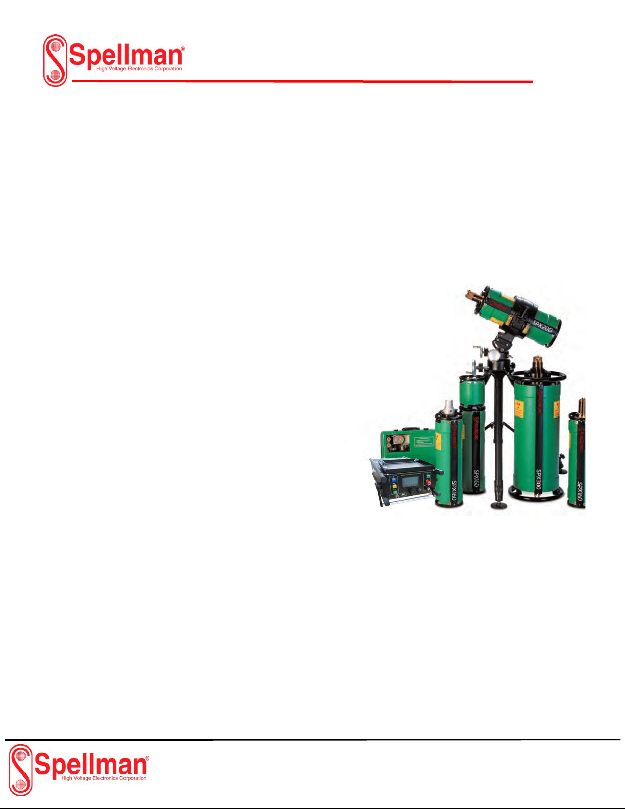
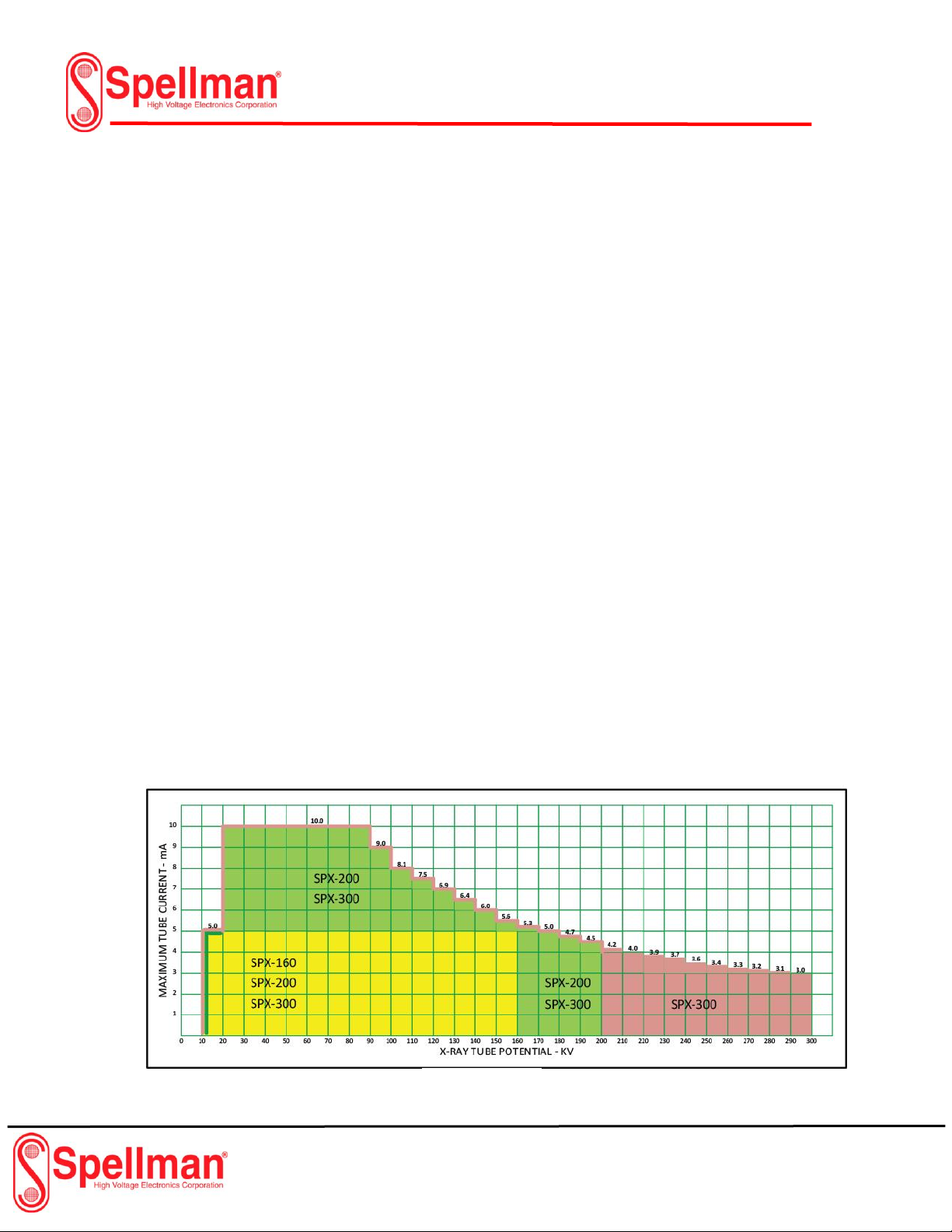
SYSTEM OVERVIEW
The SPX series can generate x-ray potential up to 160,
200 and 300 kilovolts (kV) and tube current up to 10
milliampers (mA). The maximum allowable dissipation
is 800 watts for the SPX-160 and 900W for the SPX200 and SPX-300. Maximum tube current is limited
automatically by the Control unit to 10mA, or to a value
that does not cause dissipation greater than rated
power (watts) at a set kV level.
The system offers 100% duty cycle and consists of the
following assemblies:
The Control Unit
The Tube Head
The Cooling Unit, liquid cooled units only)
The Electric Cooling Fan (air cooled units only)
These assemblies are described in detail next.
The SPX X-ray System
Figure 1-1
Page 6

SPX X-ray
Industrial Imaging System
Page 4 of 44 SPX Series System Manual
118173-001 Rev. D
The Control Unit
The radiographer uses the Control Unit to set the
radiographic exposure parameters, and to
activate/deactivate x-ray emissions from the Tube
Head. One hundred feet of cable is supplied with the
system, which enables the Control Unit and operator to
maintain a safe distance from the X-ray Tube Head
during use.
The digital-based, micro-processor-regulated Control
Unit houses all the system pushbutton operating
controls, and exposure factor Vacuum Fluorescent
Display (for display of exposure factors, a Message
Vacuum Fluorescent Screen (for display of operating
mode and system messages), and the circuitry required
to provide power to the Tube Head and Cooling Unit.
The Control Unit is enclosed in a metal chassis and a
handle is provided as a means of transporting it.
The Tube Head
The Tube Head is a cylindrical aluminum shell
assembly housing the x-ray tube, the high voltage
power supply and the filament supply. It is insulated
with sulfur hexafluoride gas that is pressurized to 50 psi
@ 70˚F. Power to operate the x-ray tube is supplied
through a shielded cable that connects the Tube Head
to the Control Unit. The x-ray tube is end-grounded,
with an exposed anode that contains a beryllium
window approximately 2 inches from the anode end.
Built-in carrying handles are at each end of the Tube
Head.
There are two Tube Head models available:
Liquid-cooled
Air-cooled
The liquid cooled Tube Head uses a separate Cooling
Unit to dissipate anode heat. These models have a
length of twin hoses attaching the Tube Head to the
Cooling Unit. Air-cooled models have an electric cooling
fan mounted at the end of Tube head. The fan is
powered by an inter-connecting cable from the Control
Unit.
The Cooling Unit (liquid cooled units only)
The Cooling Unit dissipates heat generated at the
anode of the x-ray tube. Liquid coolant from a selfcontained reservoir is pumped through one side of a
twin hose assembly into the Tube Head. Coolant flows
through a manifold in the Tube Head into the anode
and returned to the Cooling Unit through the second
half of the twin assembly.
Once in the Cooling Unit, coolant passes through a flow
switch that is electrically interlocked with the Control
Unit, and then through a filter to screen out
contaminants. The coolant exits the filter and flows
through a forced air radiator where the conducted heat
is dissipated and then back into the reservoir.
An electric motor-driven fan and pump assembly
circulates coolant and creates airflow through the
radiator. Power is supplied via an interconnecting cable
from the Control Unit. When properly connected to the
system, the Cooling Unit is automatically activated by a
switch circuit within the Control Unit.
Page 7
SPX X-ray
Industrial Imaging System
Page 5 of 44 SPX Series System Manual
118173-001 Rev. D
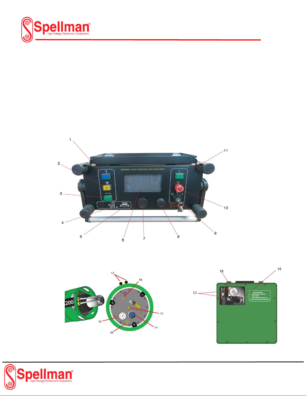
Legend – SPX X-ray System
Use the following legend as a reference for parts
identification.
1. Pre-Warning Indicator
2. X-ray Indicator
3. Interlock Indicator
4. Ethernet Port
5. RS-232 Port
6. VFD Display
7. Rotary Dial
8. Buzzer
9. Key Control
10. E-Stop
11. X-ray On Button
12. Tube Head Coolant Hose Fittings
13. Tube Head Gas Pressure Gage
14. Tube Head Cable Connector
15. Tube Head Pressure Relief Valve
16. Tube Head Gas Fill Valve
17. Cooling Unit Coolant Hose Fittings
18. Cooling Unit Reservoir Cap
19. Cooling Power Connector
20. Nut Safety
Cooling Unit
Control Unit
Tube Head Assembly
Figure 1-2
Figure 1-3
Figure 1-4
Page 8

SPX X-ray
Industrial Imaging System
Page 6 of 44 SPX Series System Manual
118173-001 Rev. D
Manual Outline
This manual provides qualified radiographers and
technicians with a means to logically inspect, operate
and maintain the SPX series portable x-ray unit. The
following paragraphs describe the arrangement of this
manual and the information contained in each section.
Chapter 1:
Introduction and General Information
This section provides general information about the
SPX series units. Included in this section is a safety
summary.
Chapter 2:
Preparation for Use and Shipment
In this chapter, the user is provided instructions for
unpacking and reshipment, along with equipment
checklists and the basic specifications for assembly.
Also included in chapter 2 are the locations of warning
labels and I.D. tags.
Chapter 3:
Installing the SPX X-ray System
This chapter provides instructions making
interconnections for both liquid cooled and air cooled
units. It also includes a description of the various
interlock connections.
Chapter 4:
SPX X-ray Controls and Indicators
Chapter 4 details the controls and indicators on the
SPX Control Unit. Refer to this chapter during use for
operational details.
Chapter 5:
SPX X-ray System Operation
The warm up and operating instructions for the SPX Xray Unit is detailed in chapter 5. Included are
descriptions of error messages.
Chapter 6:
Routine Upkeep and Care
This chapter covers preventative maintenance and care
schedules for each assembly of the system. Included
are procedures for pressurizing and refilling the Tube
Head, cleaning the apparatus and various general care
practices.
Page 9
SPX X-ray
Industrial Imaging System
Page 7 of 44 SPX Series System Manual
118173-001 Rev. D
Safety Summary
When properly installed, maintained and operated,
x-ray equipment can be used effectively and safely. If
any component of the unit is incorrectly installed,
operated by unqualified personnel, or the maintenance
schedule has been neglected, it is a potentially
dangerous apparatus.
Before operating or performing any maintenance on the
SPX series, the user MUST have a thorough
understanding of x-ray machinery, generation, high
voltage potential and x-ray control. The user MUST
understand all hazards associated with x-ray
generation.
Read this “Safety Summary” completely and thoroughly
to understand the contents. Read all of the safety
warnings, cautions and notes throughout the manual
prior to commencing any operating or maintenance
procedures.
All operators and technicians MUST adhere to the
following safety practices.
Read and understand the x-ray protection
warning published in the beginning of this
manual.
Read this manual in its entirety before
operation or maintenance is performed.
Understand all the procedures before
operating the unit.
Read thoroughly and understand completely
all NOTE, CAUTION and WARNING
statements before beginning operation or
maintenance procedures.
Use the following summary as a checklist to assure
comprehension of the safety indicators.
NOTE:
An essential operating procedure, condition or
statement, must be observed to ensure proper
understanding and operating of the system.
! CAUTION !
An operating or maintenance
procedure, practice, condition, or
statement, which, if not strictly
observed, could result in damage to,
or destruction of equipment.
! WARNING !
An operating or maintenance
procedure, practice, condition,
or statement, which, if not
strictly observed, could result in
injury to or death of personnel.
Page 10
SPX X-ray
Industrial Imaging System
Page 8 of 44 SPX Series System Manual
118173-001 Rev. D
Radiation Hazard
This equipment generates X-radiation at levels that
can be lethal. This unit must only be operated by
personnel that are certified and experienced in
industrial x-ray generation. All operators must also
understand the characteristics of radiation and the
associated dangers of exposure to primary,
secondary, and residual sources of radiation.
Lethal Voltages
High power radiation sources depend upon the
generation of extremely high, yet well-protected
voltages. Under no circumstances should the
operator access the interior of the Tube Head.
Under no circumstances should the operator
access the interior of the Control Unit or the Cooling
Unit except for the procedures outlined in Section 5
of this manual.
Badges
All personnel who work around X-ray equipment
must wear a functional exposure dosage indicator.
Radiation Protection
X-ray equipment must be operated within properly
designated protective barriers. Otherwise,
personnel must not approach closer than 100 feet
from the Tube head, and in no cases cross the
direct path of the primary beam.
Radiation Monitoring
After installation, re-installation, transporting,
performing maintenance, and during all
radiographic operations not within a radiation
enclosure, a radiation survey should be
performed.
Warm-Up Procedures
Explicit procedures are outlined for “running-up”
high voltage with new equipment, equipment with a
new tube, equipment that has been inactive for a
period of time, and for daily use. These procedures
must be strictly followed at all times.
Operation
Equipment must be operated at correct
source voltage and frequency, and must
never be left running unattended. The gas
pressure in the Tube head must be checked
to ensure it is within allowable limits before
operating the unit. Never operate this
apparatus if output voltage/current is unstable.
Cooling Unit Operation
Regularly check the coolant solution in the Cooling
Unit to ensure:
◆
the coolant level is within specification
◆
the pump circulates the coolant properly
◆
the fittings, hoses, and coolant reservoir does
not leak
Always allow the Cooling Unit, or the fan on aircooled units, to run approximately 5 minutes after
completion of x-ray generation.
Caution:
Cooling unit shipped without
coolant. Cooling unit must be
filled to the appropriate level
prior to operation.
Care in Handling
Extreme care must be taken when handling
this x-ray apparatus. Exercise caution when
packing, unpacking, shipping, and while
performing maintenance. Remember, the Xray tube is durable but breakable: be sure to
store and ship it in the upright position.
Page 11
SPX X-ray
Industrial Imaging System
Page 9 of 44 SPX Series System Manual
118173-001 Rev. D
Chapter 2:
Preparation for Use and Shipment
UNPACKING INSTRUCTIONS
The SPX X-ray Unit is shipped in a single wooden
container. To gain access to the unit, perform the
following:
◆
Remove the top cover from the crate.
◆
Carefully lift each component from the
container.
◆
Perform a thorough visual
inspection on each component.
If damage to any component has occurred,
immediately contact the carrier. Keep all damaged
containers until the carrier completes an inspection
by the carrier. If it is necessary to re-package and
ship the unit, follow the instructions outlined under
“Reshipment Guidelines”.
Reshipment Guidelines
In the event that the SPX X-ray Unit must be
transported or shipped, use the original wooden
container and packaging material whenever
possible. If the original shipping material is not
available, comply with the following re-packing
guidelines.
1. Construct a wooden shipping carton for
the Tube head Assembly similar to the
one in Figure 2-1. Build the carton so that
the top can be completely removed to
facilitate packing and unpacking.
2. Cushion the Tube head with 3" of
shock absorbent, foam type, packing
material (MINIMUM). This material
MUST surround the assembly on all
sides, including above and below the
Tube head.
3. Affix supporting blocks to the bottom
of the carton. Make sure the legs are
positioned to accommodate a pallet
jack as shown in Figure 2-1.
4. Pack the Control Unit in a
container rated for 60 lbs.
surround the Control Unit with a
MINIMUM of “2" of shock
absorbent packing material (sheet
or loose type), including the top
and bottom.
5. Pack the Cooling Unit in the
same manner as the Control Unit.
! WARNING!
The coolant solution is a flammable
substance and must be drained from
the Cooling Unit’s reservoir before it
can be shipped.
Page 12

SPX X-ray
Industrial Imaging System
Page 10 of 44 SPX Series System Manual
118173-001 Rev. D
Transporting the Unit
When transporting by commercial carrier (i.e., truck,
rail, etc.), select the shipping method and carrier on the
basis of safe shipment, especially when shipping the
fragile Tube head Assembly. Distinctly mark the Tube
head carton on all sides with labeling which provides
the carrier the following information:
◆
Contents contains fragile glass
instrumentation.
◆
Container is to be shipped in upright
container only.
Customarily, the Tube Head is shipped via air,
generally avoiding ground transportation if possible.
When shipping via air, affix an additional label to the
carton stating the following:
Figure 2-1
Tube Head Shipping Container
“Sulfur hexafluoride, non-flammable
gas is present in limited quantities in
one or more packages of this
shipment. This is to certify that the
above mentioned materials are
properly classified, described,
packaged, marked, and labeled, and
are in proper condition for
transportation according to the
applicable regulations of the U.S.
Department of Transportation.”
Page 13

SPX X-ray
Industrial Imaging System
Page 11 of 44 SPX Series System Manual
118173-001 Rev. D
EQUIPMENT CHECKLISTS
The following checklists outline the standard and
optional equipment of the SPX X-ray Unit. After
unpacking the unit, and completing a thorough visual
inspection, compare each item with this list to assure
completeness.
Note that several Tube Head models are available.
Verify that the Tube head shipped with your unit
matches the model that was originally ordered.
Checklist – Tube Head
SPX-160
Assembly, Tube Head* 3-000-0768-1
Air Cooled Unit; 40° cone,
Glass Insert
Beryllium Window
Assembly, Tube Head 3-000-0736-1
Liquid Cooled; 40° cone,
Glass Insert
Beryllium Window
Assembly, Tube Head 3-000-0772-1
Liquid Cooled; 360°
Panoramic, Glass Insert
Beryllium Window
SPX-200
Assembly, Tube Head* 3-000-3071-1
Air Cooled Unit; 40° x 60°
cone, Metal Ceramic Insert
Assembly, Tube Head 3-000-3072-1
Liquid Cooled; 40° x 60°
cone, Metal Ceramic Insert
Assembly, Tube Head 3-000-3073-1
Liquid Cooled; 360° Panoramic
Assembly, Tube Head 3-000-3258-1
Air Cooled; 40° Cone
Glass Insert
Beryllium Window
Assembly, Tube Head 3-000-3224-1
Liquid Cooled; 40° Cone
Glass Insert
Beryllium Window
SPX-300
Assembly, Tube head* 3-000-3192-1
Air Cooled Unit;
40° x 60° cone,
1.5mm Focal Spot,
1mm Beryllium
Window
Assembly, Tube head 3-000-3191-1
Liquid Cooled; 40° x 60°
cone, 1.5mm Focal Spot,
1mm Beryllium Window
* All Air Cooled Units are equipped with Fan Power
Cable (p/n: 1-040A-0355). The liquid Cooling Unit is
not equipped with this cable.
Checklist - Standard Equipment
Control Unit, Digital (1) 408574-001 (SPX160)
408574-002 (SPX200)
408574-003 (SPX300)
Cooling Unit Assembly (1) 3-000A-0737
(Liquid Cooled Units Only)
Power Cable Assembly (1) 1-040-0341
(3 Pin Connector, 25ft.) (SPX160,200,300)
Control Cable Assembly (1)
(14 Pin Connector, 100ft.) 1-040-0824 (SPX200,300)
(10 Pin Connector, 100ft.) 1-040-0342 (SPX160)
Cooler Power Cable (1)
(Liquid Cooled Units Only)
(8 Pin Connector, 50ft.) 1-040-0823
(8 Pin Connector, 100ft.) 1-040-0342 (SPX160)
Power Cable, Fan (1) 1-040-0355
(Air Cooled Units Only, 100ft.)
Interlock Jumper (1)
(Dummy Plug) 305531-001
Page 14
SPX X-ray
Industrial Imaging System
Page 12 of 44 SPX Series System Manual
118173-001 Rev. D
Checklist - Optional Equipment
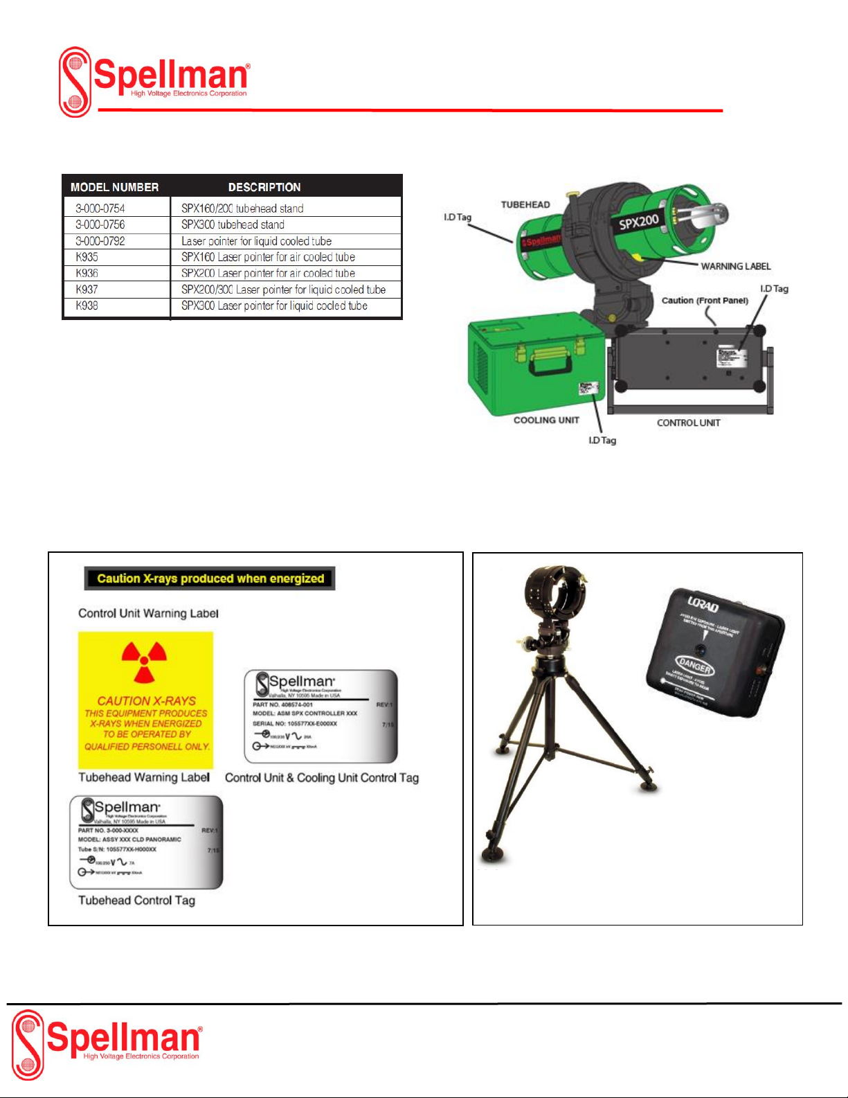
WARNINGS LABELS & CONTROL NUMBERS
Each assembly of the SPX X-ray System is equipped with an
I.D. tag (Control Tag) providing the serial number,
description, and part number. This data is used for
identification, if warranty or service information is needed,
and will be requested when contacting Spellman regarding
the apparatus.
Attached to the Control Unit and Tube head are warning
labels. Fig 2-3 illustrates the location of the I.D. tags and
warning labels for each assembly of the SPX-systems.
Figure 2-3
Figure 2-2
Tube Head Stand
Laser Pointer
Figure 2-4
Page 15
SPX X-ray
Industrial Imaging System
Page 13 of 44 SPX Series System Manual
118173-001 Rev. D
Specifications - General System
The following outlines the general operating and
environmental limits of the SPX- system.
Line Voltage: 100 to 130 VAC - 50/60 Hz,
20amps (max.); or 200 to 250VAC - 50/60 Hz,
10 amps (max.).
Line voltage selection is automatic.
The system is operable from either line
voltage range without any switch or
jumper configuration.
Operating Potential:
SPX-160: 10kV to 160kV @ 0.5 to 5.0 mA,
800 Watts maximum
SPX-200: 10kV to 200kV @ 0.5 to 10.0 mA,
900 Watts maximum
SPX-300: 10kV to 300kV @ 0.5 to 10.0 mA,
900 Watts maximum
Operating Temperature Range: -30°F to
120°F (Ambient), or -34°C to 49°C (Ambient)
Humidity: 0 to 100% relative humidity
Stabilization: kV and mA remain within 1% of
set levels. Line voltage varied from 100130/200-250 VAC.
Storage Temperature Range _ -65°F to 160°F
(-54°C to 71°C)
Figure 2-5
Page 16
SPX X-ray
Industrial Imaging System
Page 14 of 44 SPX Series System Manual
118173-001 Rev. D
Specifications - General Tube Head
See Datasheet regarding the specifications of
the Tube Head Assembly.
Tube Pressure Sense : Monitors pressure of the
SF6 gas within the Tube Head. Shuts unit down if
pressure falls below 25 psi.
Anode Thermal Sense: Monitors temperature of
the X-ray Tube Anode. Shuts down unit if Anode
temperature rises above 220°F.
Pressure Relief Valve: Automatically releases SF6
gas from Tube Head if pressure rises between 75 80 psi.
Pressure Gauge: Displays SF6 gas pressure within
Tube Head. Used in conjunction with Temperature
Compensation chart to visually inspect Tube Head
pressure.
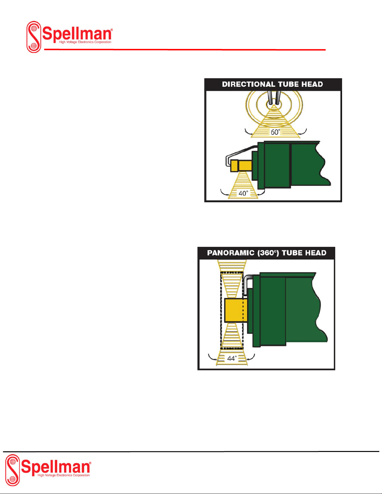
Specifications - Optional Tube Head
The information that follows furnishes the
specifications for several available Tube Head
assemblies. Figure 2-6 and 2-7 illustrate the
direction of the X-ray beam for both the 40° x 60°
cone and the 360° panoramic models.
Figure 2-6
Figure 2-7
Page 17

SPX X-ray
Industrial Imaging System
Page 15 of 44 SPX Series System Manual
118173-001 Rev. D
Specifications - Control Unit
Below are the physical and operating
specifications of the Control Unit. Included are
the physical dimensions, and the operating
indicators and controls. The controls are
explained in detail in other section of this manual.
Fluorescent Screen: Display the set KV, mA level
and show the feedback reading.
Decoder: Used to navigate through the screens
and to set KV, mA levels and time.
Control Key: Turns on the unit in warm-up position
and enables Cooler and high voltage circuit.
Buzzer: Sounds alarm when X-ray activates.
Communication Ports: Serial RS-232 and Ethernet.
X-Ray ON Switch: Green Pushbutton switch with
radiation symbol. Enables x-ray generation.
X-Ray OFF Switch: Red Pushbutton E-Stop
terminates x-ray generation. May be depressed any
time x-rays are in use.
Pre-Warning Light: Illuminates for 20 seconds max.
to indicate that X-ray will be generated.
X-Ray ON Light: Illuminates when x-ray ramps to
the pre-set level. Remains on during normal
operation until X-ray is turned off.
Safety Circuit Light: Illuminates after all interlock
circuits are closed. If light is off the controller will not
allow x-ray generation.
Figure 2-8
Page 18

SPX X-ray
Industrial Imaging System
Page 16 of 44 SPX Series System Manual
118173-001 Rev. D
Specifications - Cooling Unit
Below are the operating and physical
specifications of the Cooling Unit.
Dimensions: 12" H x 15" W x 14" L
Weight: 55 lbs. (approximate)
Coolant Solution : 14 parts methyl alcohol, 7
parts distilled water, 1 part soluble oil
(Chevron Soluble “B” )
Coolant Flow: 0.5 gallons per minute @ 50
foot-head.
Cooling Unit Connections: Self-sealing quick
disconnects.
Caution:
Cooling unit shipped
without coolant. Cooling
unit must be filled to the
appropriate level prior
to connecting the
system.
Figure 2-9
Page 19

SPX X-ray
Industrial Imaging System
Page 17 of 44 SPX Series System Manual
118173-001 Rev. D
Chapter 3:
Installing the SPX-X-ray System
PRE-OPERATIONAL
CHECKS & INSPECTION
The following paragraphs outline the steps to
properly check and inspect the SPX- X-ray unit.
Perform these
procedures before setting up the system to
ensure integrity.
Check – Tube Head Gas Pressure
This check verifies that the gas pressure inside
the Tube head assembly is within limits. Note that
Tube head gas pressure normally varies 1 psi for
every 7°F increase or decrease in ambient air
temperature.
! CAUTION !
DO NOT operate this unit if
theTube Head Pressure is below
50 psi at 70°F or damage to the
Tube Head may occur.
1. Check the Tube Head gas pressure gauge and
verify that the gas pressure is within acceptable
limits for the ambient temperature
(see Figure 1-3).
2. If the gauge indicates Tube Head gas pressure
below the acceptable limit, but greater than 5 psi,
perform the procedures for “Pressurizing the Tube
Head” (refer to section 7).
3. If Tube Head gas pressure is below 5 psi at
70°F, purge the Tube Head of all remaining gas,
then perform the procedures for “Refilling the
Tube Head” (see section 7-3).
Check - Cooling Unit
This check verifies the integrity of the Cooling Unit
(liquid cooled Tube Heads only).
1. Inspect the twin hose assembly and hose
connections for damage. The connector couplings
must be firmly attached to the hose, and the hose
must be free of punctures, frays, or dry rot.
2. Remove the Radiator cap on the Cooling Unit
and check that the coolant level is within 1/2" from
the top of the reservoir. Add coolant solution at
this time if necessary (refer to figure 4-16).
Check - Control Unit
This check verifies the integrity of the Control
Unit.
1. Perform a thorough visual inspection
for damage.
2. Check the four connectors along the
right side of the unit for foreign
material and signs of corrosion.
3. Inspect the front panel controls for
missing or broken switches and
displays.
Page 20

SPX X-ray
Industrial Imaging System
Page 18 of 44 SPX Series System Manual
118173-001 Rev. D
SYSTEM SET UP PROCEDURES
The procedures below describe the set up
procedures for both SPX Unit configurations;
liquid-cooled units, and air-cooled units. Use
Figure 3-1 (liquid-cooled), or Figure 3-2 (aircooled) as a reference while making the
necessary system connections.
System Interconnections - Liquid Cooled
The following details the connections for setting
up a liquid cooled SPX X-ray System.
! WARNING !
All cables MUST be connected
to their appropriate connectors
on the Control Unit, Cooling
Unit, and Tube Head before
applying power to the system.
1. Connect the twin hose assembly between the
Tube Head and the Cooling Unit:
_ Attach the two angled couplings to the fittings
on the back of the Tube Head.
_ Attach the couplings on the opposite end to
the female fittings on the Cooling Unit.
NOTE:
There is no designated left or right side to the
twin hose assembly. If each coupling is
properly seated, coolant flow through the
Tube Head will be achieved.
2. Install the Cooling Unit power cable:
Connect the male end of the power cable to the
connector labeled “Cooler” on the Control Unit.
Connect the female end of the power cable to the
connector on the Cooling Unit.
3. Install the Tube Head Control cable:
Connect the male end of the Control cable to the
connector labeled “Tube Head” on the Control
Unit.
Connect the female end of the Control cable to
the connector on the Tube Head base plate.
4. Install the line power cable:
Connect the female end of the line power cable to
the connector labeled “Power” on the Control Unit.
Connect the “plug” end of the line power cable to
the AC voltage source (see Connecting to Power
instructions later in this section).
5. Make the External Interlock connection:
If available, connect the Interlock cable to the
connector labeled “Interlock” on the Control Unit
(see External Interlock instructions later in this
section).
Connect the “jumper” (supplied) to the connector
labeled “Interlock” on the Control Unit for units
that do not employ an external interlock system.
Figure 3-1
SPX-System Setup (Liquid Cooled)
Page 21

SPX X-ray
Industrial Imaging System
Page 19 of 44 SPX Series System Manual
118173-001 Rev. D
System Interconnections - Air Cooled
The following details the connections for setting
up an air cooled SPX X-ray System.
! WARNING !
All cables MUST be connected
to their appropriate connectors
on the Control Unit, Cooling
Unit, and Tube Head before
applying power to the system.
1. Install the Cooling Fan power cable:
Connect the male end of the power cable
to the connector labeled “Cooler” on the
Control Unit.
Connect the female end of the power
cable to the connector on the Tube Head
base plate.
2. Install the Tube Head Control cable:
Connect the male end of the Control
cable to the connector labeled “Tube
Head” on the Control Unit.
Connect the female end of the Control
cable to the connector on the Tube Head
base plate.
3. Install the line power cable:
Connect the female end of the line power
cable to the connector labeled “Power” on
the Control Unit.
Connect the “plug” end of the line power
cable to the AC voltage source (see
Connecting to Power instructions later in
this section).
4. Make the External Interlock connection:
If available, connect the Interlock cable to
the connector labeled “Interlock” on the
Control Unit (see External Interlock
instructions later in this section).
Connect the “jumper” (supplied) to the
connector labeled “Interlock” on the
Control Unit for units that do not employ
an external interlock system.
Figure 3-2
SPX-System Setup (air-cooled)
Page 22

SPX X-ray
Industrial Imaging System
Page 20 of 44 SPX Series System Manual
118173-001 Rev. D
Connecting to Power
Note that the AC voltage source MUST be rated
as either:
120 VAC, 20 Amps, 50/60 Hz
230 VAC, 10 Amps, 50/60 Hz
External Interlock Connections
The Interlock connector on the side panel (J-4) of
the Control Unit enables the interconnection of the
x-ray enclosure doors and/or external warning
devices with the internal safety interlock circuitry
of the system. Figure 3-4 illustrates the two
circuits provided for this purpose.
Pins A and B are used to connect the enclosure
door switches. When pins A and B are properly
connected, x-ray generation is only possible when
the enclosure doors housing the Tube Head are
closed. Note that pins “A” and “B” of the interlock
connector must form a closed circuit to operate
the X-ray unit. If no external switch interlocks are
incorporated, a jumper connection is provided
within the mating connector to form the closed
circuit. Pin “B” connects to a “Fail Safe” circuit. A
24Vdc signal must be applied to pin “B” in order to
enable x-rays.
Pins “D” and “E” provide a switch closure to
operate a warning device such as a light for X-ray
Pre-warning and Pins “C” and “D” operate a
24Vdc warning device such as a light for “X-ray
On” when x-rays are being generated. The prewarning operates for a specified amount of time
before X-rays can be generated.
Pins “F” and “G” serve to confirm warning 24Vdc
indicators are functional as a test for the operator.
The signal can be configured high or low
depending on the operator preference. Pin “G”
supplies a +24V source.
Ships with standard 120Vac Plug
Figure 3-3
Figure 3-4
Page 23

SPX X-ray
Industrial Imaging System
Page 21 of 44 SPX Series System Manual
118173-001 Rev. D
Figure 3-5
Page 24

SPX X-ray
Industrial Imaging System
Page 22 of 44 SPX Series System Manual
118173-001 Rev. D
Figure 3-6
Page 25

SPX X-ray
Industrial Imaging System
Page 23 of 44 SPX Series System Manual
118173-001 Rev. D
Chapter 4:
SPX Series Controls and Indicators
The front panel is the primary user interface for
the SPX system. It includes a key switch, two
buttons, 3 indicators, a buzzer, a command dial,
with a VFD display. There are also three ports for
communications with a PC.
Pre-Warning Indicator This blue indicator
illuminates during the pre-warning time of an
exposure.
X-Ray On Indicator-This yellow indicator
illuminates during the exposure time.
Interlock Indicator -This green indicator
illuminates indicating all safety interlocks are
closed.
X-Ray On Pushbutton-This green push-button
initiates an exposure.
X-Ray Off E-Stop -This red push-button
terminates the exposure (manual mode).
Key Control- The key control has three positions:
Power Off -The system is off.
Power On- The system is powered on.
Energized- The Cooler and inverter/HV
driver is energized, and the system is ready to
enable high voltage
USB Port- Used for USB communications with a
PC. A Micro B USB connector is required for the
port. (currently unavailable)
Ethernet Port- Used for Ethernet
communications with a PC.
RS-232 Port- used for serial communications with
a PC.
Buzzer- audibly indicates when an exposure is
about to take place. It can be configured to beep
once per second during a pre-warning, beep
continuously during a pre-warning time, or be
completely disabled.
Rotary Dial- primary user control for the SPX
menu system. Turning the dial will select a
function highlighted on the screen, and
depressing the dial will execute that function.
VFD Display- primary display for system status
and for operation of the system using the menu
commands.
Figure 4-1: SPX Front Panel Layout
Figure 4-2: SPX Home Screen
Page 26

SPX X-ray
Industrial Imaging System
Page 24 of 44 SPX Series System Manual
118173-001 Rev. D
SPX Series Control Connections
The SPX Controller interfaces with all of the
necessary power and signal cables for operation
of the system. Each connector plug / receptacle
identified with a label incorporates a dedicated
military style connector for ease of connections.
Fuses- A set of 20 ampere fuses protect the main
power circuitry while a set of 10 ampere fuses
protect the cooler power circuitry A fan with an air
filter circulates air within the chassis while the unit
is in operation. Figure 4-3.
Controller Power Cable - Terminated with a
120V standard plug and a 3-pin Cannon
connector (3106-16-10) that mates with the power
input connector (J1). Figures 4-4 and 4-5.
Tube Head Interconnect Cable – Cable fitted
with two military style connectors at a minimum of
100’ in length (J3). Figures 4-6, 4-7, 4-8 and 4-9.
Cooler Power/ Interlock Cable – Provides power
to the cooling unit for either air-cooled or water
cooled units and monitors the flow rate in liquid
cooled units to prevent overheating to the X-ray
tube. (J2) Figures 4-10 and 4-11.
Interlock / Indicator Cable – Provides customer
X-ray status indicators and system safety interlock
connections. (J4) Figures 4-12 and 4-13.
Cooling Hose (Liquid Cooled Units) – Provides
coolant flow between the Cooler Unit and the
Tube Head. Figures 4-15 and 4-16.
Figure: 4-5 Power Input Cable
Figure: 4-3 SPX Control Side Panel
Figure: 4-4 Power Cable Detail
Page 27

SPX X-ray
Industrial Imaging System
Page 25 of 44 SPX Series System Manual
118173-001 Rev. D
Controller End
Cooler End
Figure 4-11 Cooler Cable 8 Pin Connector
Figure 4-9 Tube Head (160kV unit) 10 Pin Connector
Figure 4-7 Tube Head 200kV/300kV 14 Pin Connector
Figure: 4-6 Tube Head Power Cable
Tube Head End
Controller End
Figure: 4-10 Tube Head Cooling
Figure: 4-8 Tube Head Power Cable
Tube Head
Controller End
Page 28

SPX X-ray
Industrial Imaging System
Page 26 of 44 SPX Series System Manual
118173-001 Rev. D
PTO2A-16-8S
Coupling Tube Head
Figure: 4-14 Tube Head Cooler Hose
Figure 4-12 Interlock (Controller)
Figure 4-13 Interlock Connector
Coupling Cooler
Figure: 4-15 Cooler Hose Couplings
Dummy Plug: Pins “A”
and “B” connected
for interlock closure.
Page 29

SPX X-ray
Industrial Imaging System
Page 27 of 44 SPX Series System Manual
118173-001 Rev. D
SYSTEM INTERCONNECT DIAGRAM
Note: Dummy plug connected if
no external interlocks used
Figure 4-16
Page 30

SPX X-ray
Industrial Imaging System
Page 28 of 44 SPX Series System Manual
118173-001 Rev. D
SYSTEM INTERCONNECT DIAGRAM
Figure 4-17
Page 31

SPX X-ray
Industrial Imaging System
Page 29 of 44 SPX Series System Manual
118173-001 Rev. D
Chapter 5:
SPX Series Pre-operation
Before operating the unit, the X-ray Warm Up
procedures must be performed. The X-ray tube
provided with this system has been pre-aged
by the original manufacturer, and also tested
and aged by Spellman. It is necessary, however,
that the voltage be run up to the required kV
level at a fixed rate when the equipment has
not been used for a period of time.
Pre-Operational Safety Precautions
While performing the warm-up sequence, or
during
X-ray generation, the following safety
precautions must be strictly observed before
the x-ray tube is energized.
! WARNING!
To avoid radiation hazards under
unshielded, outdoor operating
conditions, the Control Unit must
be placed a considerable distance
from the Tubehead. A sufficient
length of cable is provided, and
must be used to help protect the
operator and others in the
immediate vicinity. Refer to NCRP
(National Council on Radiation
Protection) recommended
practices.
! WARNING!
The operator of this apparatus must
ensure all personnel are clear of the
hazardous X-ray area before
generating X-rays. Flashing
beacons and/or audible alarms
should be utilized during exposures,
warning personnel of the radiation
hazards. Personal radiation
monitoring devices shall be worn by
all personnel in the immediate
vicinity. Radiation warning signs
shall be posted where necessary.
! WARNING!
All cables MUST be connected to
their appropriate connectors on
the Control Unit, Cooling Unit, and
Tube Head before applying power
to the System
! WARNING!
The operator of this X-ray unit, or
any person in the immediate
vicinity, may be subject to receiving
some exposure to X-radiation
during the time that the X-ray unit
is generating X-rays. Since X-rays
can cause harmful effects to the
human body, unnecessary
exposure should be avoided, and all
exposure held to an absolute
minimum compatible with practical
requirements and current safety
regulations. An X-ray survey meter,
placed in the vicinity of the Control
Unit and operator, is recommended.
X-Ray Tube Warm Up
Seasoning “Auto-Warming” is important to
preserve the x-ray tube. It is required whenever
the tube is operated above 80 kV and four hours
have elapsed since the x-ray tube was operated
at the level required for the next exposure, or
when operating a new tube having less than ten
hours of operation. Tubes having been previously
operated, but not run over 80 kV for 30 days or
longer, must be treated as new tubes.
The following section outlines the steps to
properly complete the x-ray tube warm-up
sequence. Tables 1, 2 and 3 relate the tube’s
inactive time to the required warm-up rate and
must be used while performing the warm-up
sequence. For detailed instructions for
seasoning (auto-warming), refer to section
4.6.1 in the SPX User Guide.
Page 32

SPX X-ray
Industrial Imaging System
Page 30 of 44 SPX Series System Manual
118173-001 Rev. D
Page 33

SPX X-ray
Industrial Imaging System
Page 31 of 44 SPX Series System Manual
118173-001 Rev. D
Page 34

SPX X-ray
Industrial Imaging System
Page 32 of 44 SPX Series System Manual
118173-001 Rev. D
Chapter 6:
SPX Series System Operation
When the system is properly assembled, the
warm-up sequence complete, and all safety
precautions/practices taken, x-ray exposures can
be made by following the steps below.
All NOTES, CAUTIONS, and WARNINGS
outlined in this section must be strictly
observed to avoid damaging equipment, or
injuring personnel.
Operating Procedures
1.
If the operator has not read the "SAFETY
SUMMARY" in Chapter 1, “SAFETY
SUMMARY”, on page 1-3, and the
WARNINGS outlined under “PreOperational Safety Precautions” on page 35 in this chapter, do so before proceeding.
2.
Perform all pre-operational checks and
inspections before operating this unit. Also,
confirm that all external interlock
connections are closed, or that the jumper
is installed in the INTERLOCK connector.
! WARNING!
All cables MUST be connected to
their appropriate connectors on
the Control Unit, Cooling Unit,
and Tubehead before power is
applied to the System.
3. Make sure the SAFETY KEYSWITCH is in
the LOCKED OFF position, and then
remove the key. Turn the MAINS switch ON.
After approximately
2 seconds, the green
Safety Interlock indicator will illuminate,
and the Main Screen menu will start.
Depending on the system.
4.
Insert the key into the Safety Key
lock, then turn it to the ON
position, either the cooling fan or
the coolant pump will energize to
cool the tube.
5.
If it has been more than four hours since
the SPX was last operated or if operating
with a new
x-ray tube, it is necessary to
perform the appropriate warm-up
procedure (outlined earlier in this
chapter). If the warm-up procedure is
unnecessary, proceed to Step #6.
6.
Using the SCROLL pushbutton, select
the desired x-ray exposure time from the
standard or previous custom created
menu list.
7.
Position the film holder and Tube Head
for the ensuing exposure. Make sure all
personnel are clear of the area, and
that all external warning devices are
working properly. Insert the key into the
SAFETY KEYSWITCH and turn it to
the ON position. The SPX system is
now ready to make an exposure. Press
the X-RAY ON switch to begin the
! WARNING!
NEVER allow the x-ray unit
to run unattended. NEVER
approach the x-ray Tube
Head when power is applied,
or if the key is in the SAFETY
LOCK.
Page 35

SPX X-ray
Industrial Imaging System
Page 33 of 44 SPX Series System Manual
118173-001 Rev. D
! CAUTION!
Tube current (mA) can be
attained up to the maximum
value it can produce at the Kv
level up to the rating of the tube. At no time
should the tube be permitted to operate above
the rated current. Lower Kv settings will
inhibit x-ray generation. See specification
sheet for Kv, mA, and power ratings for the
specific SPX model number.
8.
The exposure will continue for the
duration set by the operator, after
which time the unit will automatically
shut off. During the exposure, x-ray
emission can be interrupted anytime
by pressing the red X-RAY OFF
E-STOP. To restart an interrupted
exposure, twist E-STOP button to
release and press the X-RAY ON
switch.
For detailed operation
procedures and program settings,
see section 4 of the SPX user guide
9.
At the end of the exposure, turn the key in the
SAFETY KEYSWITCH to the LOCKED OFF
position. Remove the key while making any
positioning adjustments to the Tube Head or
replacing film holders. To repeat the
exposure, re-insert the key and turn it to the
ON position and press
10.
the X-RAY ON button. If the next exposure
requires new parameters, scroll to the
appropriate menu on the display screen to set
in the new parameters, then turn the key to
the ON position and press the X-RAY ON
switch.
11.
If further operation is not necessary, leave the
key to the ON position and allow the Cooling
Unit, or cooling fan (air cooled units) to
operate for an additional five minutes.
NOTE... The Cooling Fan MUST BE allowed
to operate for five minutes after the
exposure before turning the unit OFF.
During this time, heat generated at the
anode during operation is dissipated.
12.
Turn the key to the off position. Remove the
power cord from its source, disconnect all
cables and hoses, and replace all covers.
Place the key in a safe, controlled area to
prevent unauthorized use of the unit. Store
the x-ray unit in a cool, dry location that
provides secure storage.
FAULT MESSAGES
During operation, if a fault condition occurs, x-ray
generation is automatically terminated and FAULT
messages will appear on the displayscreen. The
following table lists the fault messages that may
appear and instructions on how to remedy the
fault.
1. Interlock: The connection between pins
"A" and "B" of the INTERLOCK connector
has been interrupted. Check that the
interlocked enclosure door switches are
operable and closed, or that the jumper is
properly installed.
2. Temperature/Pressure: The Tube Head has
overheated or the gas pressure has dropped
below 25 psi. Make sure the Cooling Fan is
working properly. Check the gas pressure within
the Tubehead. If the pressure is below 25 psi @
70º F, perform the Re-pressurization
procedures in Chapter 7, “Re-Pressurizing the
Tube Head”, on page 33 of this manual.
3. Arc Detected: This fault condition is usually
due to instability from a new tube or from an
inadequate warm up sequence. Re-start the
system and perform an additional warm up
sequence. If the ARC DETECTED fault occurs
repeatedly on restart, service is necessary.
4. Over Voltage: This condition occurs if the
output voltage kV exceeds a factory set level. If
the Over Voltage fault occurs repeatedly after
restart, service is necessary.
Page 36

SPX X-ray
Industrial Imaging System
Page 34 of 44 SPX Series System Manual
118173-001 Rev. D
FAULT MESSAGES (Cont.)
GUI Display
Page 37

SPX X-ray
Industrial Imaging System
Page 35 of 44 SPX Series System Manual
118173-001 Rev. D
FAULT MESSAGES (Cont.)
Fault Descriptions
Fault Indicator
Description
Transformer OC Fault
Transformer Over Current Fault
LVPS-15V Fault
Low Voltage Power Supply -15V Under/ Over Voltage
LVPS+ 15V Fault
Low Voltage Power Supply +15V Under/ Over Voltage
Watch Dog Fault
Firmware Timeout
Tube Head X-ray On Lamp Fault
X-Ray “on” Lamp Fault
Prewarn Lamp Fault
Front Panel Pre-warning Lamp Fault
Cooler Select Fault
X-ray Tube Cooler Fault
DC Rail Fault
DC Switch Voltage Drive Fault
AC Line Fault
Line Voltage Incorrect
Over Temp. Fault
Over Temperature Power Supply
Power Supply Fault
Power Supply Inhibited Due to 1 or More Faults
PT Interlock Fault
Pressure/Temperature Tube Head Fault
OV Fault
Over Voltage Fault
UV Fault
Under Voltage Fault
OC Fault
Power Supply Output Over Current Fault
UC Fault
Power Supply Under Current Fault
Over Power Fault
Power Supply Exceeded Power Rating
Filament Regulator Fault
X-Ray Tube Filament Current Regulator Not Working Properly
Inverter Fault
HV Transformer Primary Drive Not Working Correctly
Inverter OT Fault
Temperature on Inverter Driver too High
Cooler Interlock Fault
Coolant Not Flowing Through X-ray Tube
FP X Ray ON Lamp Fault
Front Panel X-Ray On Lamp Not Working
ARC Fault
Power Supply or X-Ray-Tube ARC Occurred
External Interlock Fault
External Interlock Pins A & B not Jumped
Light Confirm
External Light Fault
Page 38

SPX X-ray
Industrial Imaging System
Page 36 of 44 SPX Series System Manual
118173-001 Rev. D
Chapter 7:
SPX Series Routine Care and Maintenance
Introduction
The SPX Series Portable X-ray Unit is a reliable,
easily maintained, industrial x-ray device. With
modest amounts of upkeep and care, this system
will provide years of trouble free operation. This
chapter provides inspections and maintenance
practices, that when followed, reduce the
possibility of equipment breakdown, and optimize
the unit's reliability.
Some of these practices are conducted in
accordance to a pre-arranged schedule
(inspections and cleaning), while others require
attention only when the need arises (repressurizing the Tube Head).
Inspection Checklist
To assist in early detection of potential problems,
the following "Inspection Checklist" should be
followed. Discrepancies discovered during these
inspections must be noted and immediately
corrected to avoid the possibility of equipment
breakdown. The inspections described in these
checklists should be performed in accordance
with general care and maintenance of this
product.
NOTE... When operating in harsh
environments, the following inspection
checklists must be performed more often due
to the higher concentration of dust and debris
accumulating within each assembly
Page 39

SPX X-ray
Industrial Imaging System
Page 37 of 44 SPX Series System Manual
118173-001 Rev. D
Care and Maintenance
During normal periods of use, but especially in
harsh environmental operating conditions, it
becomes necessary to clean each assembly of
the system. This cleaning should be performed
once a month under normal operating condition,
to optimize performance, and minimizes
equipment failure during use.
Required Cleaning Materials
•
Clean lint free cloths;
•
Mild detergent;
•
1 inch soft bristled paint brush;
•
Electronic cleaning solution;
•
Acid brushes;
•
Low pressure air station, hose and
nozzle set.
Control Unit Maintenance
! WARNING!
Under no circumstances should
the interior of the Tube Head be
accessed. When cleaning the
Control Unit, power MUST be
OFF and the unit MUST be
disconnected from the power
source.
1.
Dampen a clean lint free cloth in a
solution of warm water and mild
detergent. Wring any excess water from
the cloth to prevent dripping. Remove
dirt, dust, or debris from the top cover of
the Control Unit. Clean the outer casing
of the Tube Head and Control Unit.
2.
Remove dirt, dust, or debris from the
front panel of the Control Unit using a 1"
soft bristled paint brush. Dirt that is not
easily dislodged can be removed with a
lint free cloth dampened in a warm water
and mild detergent solution.
3.
Remove the top cover from the Control
unit by first removing the bolts from the
two top tubular side rails and then
removing the screws from the top panel.
Carefully remove the top cover. Using a
low pressure air and nozzle system,
blow any dirt, dust, or debris out of the
unit. Re-install the top cover and the
side rails
NOTE... Material that cannot be
removed from around circuitry can be
cleaned using a standard electronic
cleaning solution and an acid brush.
4.
Inspect the connectors on each cable
assembly. Remove any dirt, dust, debris,
or foreign material from the pins/sockets
with electronic cleaning solution and an
acid brush. DO NOT use water. Check
for corrosion on the pins or connectors
and remove if necessary.
Tube Head Maintenance
The following paragraphs describe the
general maintenance procedures to be
performed periodically on the Tube Head
assembly. Outlined below are the steps for
Re-pressurizing the Tube Head with sulfur
hexafluoride gas, and the conditions under
which each are performed. A Temperature
Compensation chart is provided for use
while conducting these tasks.
NOTE... A charger and
maintenance kit (P/N 9-200-0102) for the
Tubehead is available, and can be
purchased through Spellman.
Page 40

SPX X-ray
Industrial Imaging System
Page 38 of 44 SPX Series System Manual
118173-001 Rev. D
Re-Pressurizing the Tube Head
This x-ray unit can be safely operated at
Tube Head pressures as low as 50 psi @
70º F. Should the Tube Head pressure fall
below this value, but remain above 5 psi (as
indicated on the pressure gauge), the Tube
Head will need re-pressurizing.
The following procedures outline repressurizing the Tube Head to 50 psi with
dry sulfur hexafluoride gas (SF6) at 70º F
through the charging valve (automobile tire
type) on the back of the Tube Head. Use a
hose incorporated with a relief valve or
pressure regulator, and a gauge having an
accuracy of at least ±4 psi. Refer to Figure
7 -1 and Figure 7-2 while performing these
procedures.
! CAUTION!
DO NOT re-pressurize if Tube
Head pressure has fallen below
5 psi @ 70º F. Such low
pressures may have caused
contaminants to enter the Tube
Head chamber, and can cause
damage from high voltage
arcing. If pressure is below 5
psi, the Tube Head must be
purged of all remaining gas,
then re-filled. If the Tube Head
gas pressure is below 5 psi @
70º F, the Tube Head service is
necessary.
1.
Remove the protective cover from the
SF6 (sulfur hexafluoride) cylinder.
Remove the plug from the cylinder
valve with a 3/8" allen wrench. The
cylinder valve outlet is left-hand
threaded.
! WARNING!
Extreme care must be exercised
while handling the cylinder so as
not to drop it after the protective
cover has been removed. The
cylinder must be chained to a
stationary post or otherwise
secured against tipping.
2.
Connect the SF6 charging regulator
assembly, or equivalent, to the SF
6
cylinder valve.
NOTE... The pressure regulator
supplied with the optional Spellman
recharge kit is factory set to 70 – 75 psi
@ 70˚ F., and locked with a hex nut on
the adjustment knob. However , due to
spring tension ageing. And/or various
ambient temperatures, this setting may
need to be updated.
3.
Connect the Tube Head to the
regulator assembly using the
hose, as shown in Figure 7-1.
Leave the SF6 cylinder closed
at this time. For this procedure,
hose and pump are not required.
4.
Open the vacuum line valve slightly, to
purge the hose of standing air. Open
the SF6 gas cylinder slightly to purge
the regulator of any standing air. Now
close the vacuum line valve and open
the SF
6
cylinder valve to its fully open
position (against its physical stop).
5.
The Tube Head will begin filling with
SF6. When the Tube Head gauge
indicates the correct pressure, close the
SF6 cylinder valve. To determine the
correct pressure, refer to the "Pressure
vs. Temperature" chart (Figure 7-2).
6.
Remove the charging hose connection
at the Tube Head. Secure the gas
cylinder by removing the connections
Page 41

SPX X-ray
Industrial Imaging System
Page 39 of 44 SPX Series System Manual
118173-001 Rev. D
and replacing the protective cover.
Recheck the pressure and inspect the
Tube Head for leakage.
Legend – Tube Head Pressurization Set Up
1.
Tube Head
2.
SF6 (sulfur hexafluoride) cylinder
3.
Cylinder Valve
4.
Pressure Gauge
5.
Charging Regulator Assembly
6.
Vacuum Line Valve
7.
Hose
8.
Hose
9.
Vacuum Pump
Temperature Compensation
As shown in Figure 7-2, temperature
changes cause SF6 gas to expand or
contract at the rate of 1 psi for every
7oF
increase/decrease in ambient air
temperature.
Allowances for these changes
must be made when checking the Tube
Head gas pressure, or while
re-pressurizing/re-filling the Tube Head.
Figure 7-2 charts the maximum and
minimum pressure limitation of the Tube
Head at various temperature ranges. This
chart is to be used whenever the Tube
Head is inspected,
re-pressurized, or re-filled.
Note… It is standard practice to allow
both the gas supply and the Tube Head to
achieve room temperature before attempting
to re-pressurize. Temperature equilibrium
eliminates errors resulting from differences
between the gas supply and the Tube Head
temperatures.
Figure 7-1 Tube Head Pressurization Setup
Figure 7-2 Pressure vs Temperature Chart
Page 42

SPX X-ray
Industrial Imaging System
Page 40 of 44 SPX Series System Manual
118173-001 Rev. D
Re-Filling the Tube Head
This procedure is used when the pressure within
the Tube Head has dropped below 5 psi @ 70˚F,
or after major maintenance on the Tube Head has
occurred. To re-fill the Tube Head, follow the
procedures outlined below while referring to
figures 7-1 and 7-2.
1) Remove the protective cover from the
SF6 cylinder (2) Remove the plug from
the cylinder valve (3) with a 3/8” Allen
Wrench. The cylinder valve outlet is lefthand threaded.
Warning!
Extreme care must be exercised
while handling the cylinder so as
not to drop it after the protective
cover has been removed.
2) Connect the SF6 charging regulator
assembly (6) to the SF6 cylinder valve.
Note… the pressure regulator supplied
with the optional recharge kit is factory set to
50 psi @ 70˚F, and locked with a hex nut on
the adjustment knob. However, due to spring
tension aging, and/or various ambient
temperatures, this setting may need to be
updated.
3) Connect the vacuum pump (10) and the
Tube Head (1) to the regulator assembly
(6), using the hoses (7) and (8) as shown
in figure 7-1.
4) Leaving the SF6 gas cylinder valve (3)
closed, open the vacuum line (6) counterclockwise.
5) Start the vacuum pump and allow it to run
for at least 20 minutes for 160kV, (1 hour
for 200kV and 300kV units). The final
vacuum indicated on the regulator gauge
should be at least 25” Hg.
6) Close the vacuum line (6) and turn the
vacuum pump off. Open the SF6 cylinder
valve (3) to its’ fully open position (until
reaching its’ physical stop). Fill the Tube
Head until the gauge indicates 25 psi,
then close the cylinder valve.
7) Open the vacuum valve and run the pump
an additional hour. Close the vacuum line
and stop the pump. Open the SF6
cylinder valve again and fill the Tube
Head to the pressure indicated on the
“Pressure vs Temperature” chart
(Figure 7-2). When the Tube Head is at
the correct pressure, close the SF^
cylinder valve.
8) Remove the charging hose connection at
the Tube Head, secure the gas cylinder,
and replace the protective cover. Recheck the pressure and inspect the Tube
Head for leaks.
Page 43

SPX X-ray
Industrial Imaging System
Page 41 of 44 SPX Series System Manual
118173-001 Rev. D
Page 44

SPX X-ray
Industrial Imaging System
Page 42 of 44 SPX Series System Manual
118173-001 Rev. D
SPX-160kV, 200kV and 300kV TUBEHEAD
PRESSURE SETUP
RECOVER SF6 GAS
START
FILL NEW SF6 GAS
Connect New SF6 Cylinder Gas to
Tube Head
Start fill SF6 gas
When gauge indicates 25 psi, Stop to
this process
FINAL FILL NEW
SF6 GAS
CHECK TUBE HEAD
LEACK
Connect Recover SF6 Cylinder to
Tube Head
Fill Recover SF6 gas
When gauge indicates 20 psi, Stop
this process
Check for a leak
VACUUM THE TUBE
HEAD
Connect SF6 Gas Re-claimer to the
Tube Head
Start Re-claimer Process
When Vacuum gauge indicate least
10“Hg, switch to vacuum Pump
Vacuum for 20 minutes(1 hour for 200
and 300kV systems)
Vacuum gauge should indicate least
25” Hg
Connect New SF6 Cylinder Gas to
Tube Head
Start fill SF6 gas
When gauge indicates 55 psi, Stop
this process
Connect SF6 Gas Re-claimer to the
Tube Head
Start Re-claimer Process
When Vacuum gauge indicate least
10“Hg, switch to vacuum Pump
Vacuum for 20 minutes (1 hour for 200
and 300kV systems)
Vacuum gauge should indicate least
25” Hg
Page 45

SPX X-ray
Industrial Imaging System
Page 43 of 44 SPX Series System Manual
118173-001 Rev. D
COOLING UNIT UPKEEP
The following paragraphs describe the monthly
general maintenance procedures for the Cooling
Unit. These tasks include mixing/adding coolant
solution, cleaning the air filter, and cleaning the
coolant filter. Note that the frequency of these
procedures should be adjusted appropriately
during times of heavy use or while operation
under severe environmental conditions.
Mixing & Adding Coolant Solution
After prolonged use (due to evaporation or
spillage), or after performing maintenance on the
Cooling Unit, add coolant solution to the reservoir.
The following procedures describe the methods
used to properly formulate and add coolant
solution to the Cooling Unit.
1. A plastic container is needed to mix and store
the coolant solution. The container should be
appropriately sized to accommodate easy
handling, have a means of pouring the solution,
and a means of capping it off for storage.
2. In this container mix 14 parts of methyl alcohol,
with 7 parts distilled water, and 1 part soluble oil
(Chevron Soluble D or MOBIL S-122 Soluble).
Gently agitate the container to help blend the
solution.
3. Remove the top cover from the Cooling Unit,
then remove the radiator cap. Check that the
coolant level is within specifications. If the coolant
level is more than 1/2" from the top of the
reservoir, add coolant solution to the reservoir
until the level is approximately 1/2" from the top,
then replace the radiator cap.
4. Install the twin hose assembly between the
Cooling Unit and the Tube Head. Connect the
power cable between the Control Unit and the
Tube Head, and the power cord between the
Control Unit and the Cooling Unit. Turn the Key to
ON position and allow the coolant to circulate
through the system for approximately three
minutes.
5. Turn the system OFF and remove the radiator
cap. Inspect the coolant level and ensure it
remained within 1/2" from the top of the reservoir.
Add more coolant solution if necessary, and
repeat step 4.
! CAUTION !
Store the coolant container in a cool, dry
area with the cap on. Clearly mark the
container so that the contents are easily
identifiable.
Cleaning - Cooling Unit Air Filter
Clean the wire mesh air filter within the Cooling
Unit each month to remove dust, dirt, or debris
collected during use. Large accumulations of dirt
can impede the flow of air through the radiator
assembly, resulting in restricted or limited
cooling of the anode. The following procedures
describe the steps to remove and clean the
Cooling Unit’s air filter.
1. Release the four latches that fasten the top
cover to the Cooling Unit, then lift the cover off the
unit. Remove the ten screws from the top plate,
and the four bolts from the bottom of the case. Lift
the entire Cooling Unit chassis from the protective
case.
2. Remove the four screws (with nuts) securing
the grille and filter to the inner side of the
protective case.
3. Remove dirt, dust, or debris from the filter by
washing it in a solution of mild detergent and
warm water. When complete, rinse the filter
thoroughly with clean, warm water. DO NOT use
gasoline or other solvents to clean the filter. Allow
the filter to dry completely, or blow off any
remaining moisture with compressed air.
4. Re-install the filter and grille assembly to the
protective case. DO NOT over tighten the
mounting hardware or distortion to the filter frame
may occur.
5. Insert the Cooling Unit chassis into the
protective
case. Make sure the filter assembly is positioned
directly in front of the radiator before tightening
mounting hardware.
Page 46

SPX X-ray
Industrial Imaging System
Page 44 of 44 SPX Series System Manual
118173-001 Rev. D
Cleaning - Coolant Filter
The Cooling Unit contains a screen-type filter
contained within the in-line strainer assembly.
This filter is attached to the Cooling Unit chassis.
To prevent restricted coolant flow and overheating of the anode, perform this inspection and
cleaning procedure every month.
1. Release the four latches that fasten the top
cover to the Cooling Unit, then lift the cover off the
unit. Remove the ten screws from the top plate,
and the four bolts from the bottom of the case. Lift
the entire Cooling Unit chassis from the protective
case.
2. Unscrew and remove the cap nut from the
strainer assembly (expect coolant solution to seep
out while the cap is removed). Lift the
filter/strainer out of the assembly, and quickly
replace the cap nut to stem the flow of coolant
solution.
3. Remove contaminants from the filter with a
solution of warm water and mild detergent. The
screen is made of delicate material and can be
deformed quite easily. Handle the filter with
extreme care.
4. Rinse the filter in clean, warm water to remove
excess detergent. Remove the cap nut and reinstall the filter. Replace the cap nut and tighten.
5. Add coolant solution to the reservoir to
compensate for spillage that occurred during
cleaning. Clean any coolant solution from the
chassis that leaked out during this procedure.
Install the chassis into the protective case.
6. Attach the twin hose assembly between the
Cooling Unit and the Tube Head, and the Control
Unit to the Cooling Unit. Apply power, and allow
coolant to circulate for three minutes. Re-check
the coolant level to ensure it is 1/2" from the top.
Add Cooling Solution as needed.
Page 47

IMPORTANT SAFETY PRECAUTIONS
SAFETY
OBSERVE EXTREME CAUTION WHEN WORKING WITH THIS EQUIPMENT.
SERVICING SAFETY
.
THIS POWER SUPPLY GENERATES VOLTAGES THAT ARE DANGEROUS AND MAY BE
High voltage power supplies must always be grounded.
Do not touch connections unless the equipment is off and the
Capacitance of both the load and power supply is discharged.
Allow five minutes for discharge of internal capacitance of the power supply.
Do not ground yourself or work under wet or damp conditions.
FATAL.
Maintenance may require removing the instrument cover with the power on.
Servicing should be done by qualified personnel aware of the electrical hazards.
WARNING note in the text call attention to hazards in operation of these units
that could lead to possible injury or death.
CAUTION notes in the text indicate procedures to be followed to avoid possible
damage to equipment.
Copyright 2000, Spellman High Voltage Electronics Corporation. All Rights Reserved.
This information contained in this publication is derived in part from proprietary and patent data. This information has
been prepared for the express purpose of assisting operating and maintenance personnel in the efficient use of the
model described herein, and publication of this information does not convey any right to reproduce it or to use it for
any purpose other than in connection with installation, operation, and maintenance of the equipment described.
118091-001 REV. B
Page 48

WICHTIGE SICHERHEITSHIN W EISE
SICHERHEIT
DIESES HOCHSPANNUNGSNETZTEIL ERZEUGT LEBENSGEFÄHRLICHE HOCHSPANNUNG.
SEIN SIE SEHR VORSICHTIG BEI DER ARBEIT MIT DIESEM GERÄT.
Das Hochspannungsnetzteil muß immer geerdet sein.
Berühren Sie die Stecker des Netzteiles nur, wenn das Gerät ausgeschaltet ist und die elektrischen
Kapazitäten des Netzteiles und der angeschlossenen Last entladen sind.
Die internen Kapazitäten des Hochspannungsnetzteiles benötigen ca. 5 Minuten, um sich zu entladen.
Erden Sie sich nicht, und arbeiten Sie nicht in feuchter oder nasser Umgebung.
SERVICESICHERHEIT
Notwendige Reparaturen können es erforderlich machen, den Gehäusedeckel während des Betriebes zu
entfernen.
Reparaturen dürfen nur von qualifiziertem, eingewiesenem Personal ausgeführt werden.
“WARNING” im folgenden Text weist auf gefährliche Operationen hin, die zu Verletzungen oder zum Tod
führen können.
“CAUTION” im folgenden Text weist auf Prozeduren hin, die genauestens befolgt werden müssen, um
eventuelle Beschädigungen des Gerätes zu vermeiden.
118091-001 REV. B
Page 49

PRECAUTIONS IMPORTANTES POUR VOTRE SECURITE
CONSIGNES DE SÉCURITÉ
CETTE ALIMENTATION GÉNÈRE DES TENSIONS QUI SONT DANGEUREUSES ET PEUVENT ÊTRE FATALES.
OYEZ EXTRÊMENT VIGILANTS LORSQUE VOUS UTILISEZ CET ÉQUIPEMENT.
S
Les alimentations haute tension doivent toujours être mises à la masse.
Ne touchez pas les connectiques sans que l’équipement soit éteint et que la capacité à la fois de la charge et de
l’alimentation soient déchargées.
Prévoyez 5 minutes pour la décharge de la capacité interne de l’alimentation.
Ne vous mettez pas à la masse, ou ne travaillez pas sous conditions mouillées ou humides.
CONSIGNES DE SÉCURITÉ EN CAS DE REPARATION
La maintenance peut nécessiter l’enlèvement du couvercle lorsque l’alimentation est encore allumée.
Les réparations doivent être effectuées par une personne qualifiée et connaissant les risques électriques.
Dans le manuel, les notes marquées « WARNING » attire l’attention sur les risques lors de la manipulation de ces
équipements, qui peuvent entrainer de possibles blessures voire la mort.
Dans le manuel, les notes marquées « CAUTION » indiquent les procédures qui doivent être suivies afin d’éviter
d’éventuels dommages sur l’équipement.
118091-001 REV. B
Page 50

IMPORTANTI PRECAUZIONI DI SICUREZZA
SICUREZZA
PONI ESTREMA CAUTELA QUANDO OPERI CON QUESO APPARECCHIO.
QUESTO ALIMENTATORE GENERA TENSIONI CHE SONO PERICOLOSE E
POTREBBERO ESSERE MORTALI.
Gli alimentatori ad alta tensione devono sempre essere collegati ad un impianto di terra.
Non toccare le connessioni a meno che l’apparecchio sia stato spento e la capacità
interna del carico e dell’alimentatore stesso siano scariche.
Attendere cinque minuti per permettere la scarica della capacità interna dell’alimentatore
ad alta tensione.
Non mettere a terra il proprio corpo oppure operare in ambienti bagnati o saturi d’umidità.
SICUREZZA NELLA MANUTENZIONE.
Manutenzione potrebbe essere richiesta, rimuovendo la copertura con apparecchio
acceso.
La manutenzione deve essere svolta da personale qualificato, coscio dei rischi elettrici.
Attenzione alle AVVERTENZE contenute nel manuale, che richiamano all’attenzione ai
rischi quando si opera con tali unità e che potrebbero causare possibili ferite o morte.
Le note di CAUTELA contenute nel manuale, indicano le procedure da seguire per
evitare possibili danni all’apparecchio.
118091-001 REV. B
Page 51

To obtain information on Spellman’s product warranty please visit our website at:
http://www.spellmanhv.com/en/About/Warranty.aspx
 Loading...