

Page 1

R
PMX
Instruction Manual
MODEL :
SERIAL# :
DATE :
SPELLMAN
HIGH VOLTAGE ELECTRONICS
CORPORATION
475 Wireless Blvd.
Hauppauge, New York, 11788
+1(631) 630-3000*FAX: +1(631) 435-1620*
E-mail: sales@spellmanhv.com
Website: www.spellmanhv.com
High Voltage Power Supply
PMX MANUAL 118163-001 Rev A
Page 2

IMPORTANT SAFETY PRECAUTIONS
SAFETY
THIS POWER SUPPLY GENERATES VOLTAGES THAT ARE DANGEROUS AND MAY BE FATAL.
OBSERVE EXTREME CAUTION WHEN WORKING WITH THIS EQUIPMENT.
High voltage power supplies must always be grounded.
Do not touch connections unless the equipment is off and the
Capacitance of both the load and power supply is discharged.
Allow five minutes for discharge of internal capacitance of the power supply.
Do not ground yourself or work under wet or damp conditions.
SERVICING SAFETY
.
Maintenance may require removing the instrument cover with the power on.
Servicing should be done by qualified personnel aware of the electrical hazards.
WARNING note in the text call attention to hazards in operation of these units
that could lead to possible injury or death.
CAUTION notes in the text indicate procedures to be followed to avoid possible
damage to equipment.
Copyright © 2000, Spellman High Voltage Electronics Corporation. All Rights Reserved.
This information contained in this publication is derived in part from proprietary and patent data. This information has
been prepared for the express purpose of assisting operating and maintenance personnel in the efficient use of the
model described herein, and publication of this information does not convey any right to reproduce it or to use it for
any purpose other than in connection with installation, operation, and maintenance of the equipment described.
118004-001 REV. B
Page 3

WICHTIGE SICHERHEITSHINWEISE
SICHERHEIT
DIESES HOCHSPANNUNGSNETZTEIL ERZEUGT LEBENSGEFÄHRLICHE HOCHSPANNUNG.
SEIN SIE SEHR VORSICHTIG BEI DER ARBEIT MIT DIESEM GERÄT.
Das Hochspannungsnetzteil muß immer geerdet sein.
Berühren Sie die Stecker des Netzteiles nur, wenn das Gerät ausgeschaltet ist und die elektrischen
Kapazitäten des Netzteiles und der angeschlossenen Last entladen sind.
Die internen Kapazitäten des Hochspannungsnetzteiles benötigen ca. 5 Minuten, um sich zu entladen.
Erden Sie sich nicht, und arbeiten Sie nicht in feuchter oder nasser Umgebung.
SERVICESICHERHEIT
Notwendige Reparaturen können es erforderlich machen, den Gehäusedeckel während des Betriebes zu
entfernen.
Reparaturen dürfen nur von qualifiziertem, eingewiesenem Personal ausgeführt werden.
“WARNING” im folgenden Text weist auf gefährliche Operationen hin, die zu Verletzungen oder zum Tod
führen können.
“CAUTION” im folgenden Text weist auf Prozeduren hin, die genauestens befolgt werden müssen, um
eventuelle Beschädigungen des Gerätes zu vermeiden.
118004-001 REV. B
Page 4

PRECAUTIONS IMPORTANTES POUR VOTRE SECURITE
CONSIGNES DE SÉCURITÉ
CETTE ALIMENTATION GÉNÈRE DES TENSIONS QUI SONT DANGEUREUSES ET PEUVENT ÊTRE FATALES.
OYEZ EXTRÊMENT VIGILANTS LORSQUE VOUS UTILISEZ CET ÉQUIPEMENT.
S
Les alimentations haute tension doivent toujours être mises à la masse.
Ne touchez pas les connectiques sans que l’équipement soit éteint et que la capacité à la fois de la charge et de
l’alimentation soient déchargées.
Prévoyez 5 minutes pour la décharge de la capacité interne de l’alimentation.
Ne vous mettez pas à la masse, ou ne travaillez pas sous conditions mouillées ou humides.
CONSIGNES DE SÉCURITÉ EN CAS DE REPARATION
La maintenance peut nécessiter l’enlèvement du couvercle lorsque l’alimentation est encore allumée.
Les réparations doivent être effectuées par une personne qualifiée et connaissant les risques électriques.
Dans le manuel, les notes marquées « WARNING » attire l’attention sur les risques lors de la manipulation de ces
équipements, qui peuvent entrainer de possibles blessures voire la mort.
Dans le manuel, les notes marquées « CAUTION » indiquent les procédures qui doivent être suivies afin d’éviter
d’éventuels dommages sur l’équipement.
118004-001 REV. B
Page 5

IMPORTANTI PRECAUZIONI DI SICUREZZA
SICUREZZA
QUESTO ALIMENTATORE GENERA TENSIONI CHE SONO PERICOLOSE E
POTREBBERO ESSERE MORTALI.
PONI ESTREMA CAUTELA QUANDO OPERI CON QUESO APPARECCHIO.
Gli alimentatori ad alta tensione devono sempre essere collegati ad un impianto di terra.
Non toccare le connessioni a meno che l’apparecchio sia stato spento e la capacità interna
del carico e dell’alimentatore stesso siano scariche.
Attendere cinque minuti per permettere la scarica della capacità interna dell’alimentatore
ad alta tensione.
Non mettere a terra il proprio corpo oppure operare in ambienti bagnati o saturi d’umidità.
SICUREZZA NELLA MANUTENZIONE.
Manutenzione potrebbe essere richiesta, rimuovendo la copertura con apparecchio
acceso.
La manutenzione deve essere svolta da personale qualificato, coscio dei rischi elettrici.
Attenzione alle AVVERTENZE contenute nel manuale, che richiamano all’attenzione ai
rischi quando si opera con tali unità e che potrebbero causare possibili ferite o morte.
Le note di CAUTELA contenute nel manuale, indicano le procedure da seguire per evitare
possibili danni all’apparecchio.
118004-001 REV. B
Page 6

Contents
CHAPTER 1 INTRODUCTION ....................................................2
1.1 PMX DESCRIPTION...............................................2
1.1.1 Power Supply Requirements ................................3
1.1.2 Environment Requirements ..................................4
1.2 THEORY OF OPERATION ....................................4
1.2.1 Function Overview ...............................................4
1.2.2 Line Rectification and Filterin g ...........................4
1.2.3 Inverter .................................................................4
1.2.4 High Voltage Transformer ...................................4
1.2.5 High Voltage Assembly ........................................4
1.2.6 System Control PWB ............................................4
1.2.7 Filament Power Supply ........................................5
1.2.8 High Speed Starter ...............................................6
1.3 SAFETY ...................................................................7
1.3.1 Safety and Warning Symbols ................................7
CHAPTER 2 INSTALLATION .....................................................8
2.1 INTRODUCTION ....................................................8
2.2 UNPACKING ..........................................................8
2.3 OVERALL CONNECTIONS ............................................8
2.4 POWER LINE MAINS .......................................... 10
2.5 Cable connection illustration ............................. 10
2.5.1 HV Cable Connection ........................................ 10
2.5.2 Stator Cable Connection .................................... 11
2.5.3 Filament Driver Cable Connection .................... 11
2.6 MULTI INTERFACE CABLE CONNECTIONS .. 12
2.6.1 Pin Layout of the Multi interface ....................... 12
2.7 INTERLOCK CONNECTIONS ...................................... 14
2.8 TUBE CURRENT MONITOR CONNECTION................. 14
2.9 GROUND CONNECTION .................................... 14
2.9.1 X-Ray Tube Housing Ground ............................. 14
2.9.2 Chassis Ground .................................................. 15
2.10 FINAL CHECKS .................................................... 15
2.11 GUI SOFTWARE .................................................. 15
CHAPTER 3 ........................................................................... 17
INTERFACING ........................................................................ 17
3.2 MULTI INTERFACE............................................. 17
3.2.1 Connector Style and Pin Layout ........................ 17
3.2.2 Serial Communication Interface ........................ 18
3.2.3 Digital I/O Control Inte rface ............................. 19
3.2.4 Remote Status Interface ..................................... 20
3.2.5 Remote Monitoring Interface ............................. 22
3.3 ETHERNET INTE RFACE ............................................. 22
CHAPTER 4 CONFIGURATION, CAL IBRATION AND
OPERATION .......................................................................... 23
4.1 INTRODUCTION ........................................................ 23
4.2 TUBE PREHEAT TABLE CONFIGURATION .................. 23
4.3 FILAMENT AU TO -CALIBRATION ............................... 25
4.4 OPERATING X-RAY EXPOSURES ............................... 26
4.4.1 Normal Exposure ............................................... 26
4.4.2 AEC Exposure .................................................... 28
4.4.3 Smart AEC Exposure ......................................... 29
CHAPTER 5 ........................................................................... 32
TROUBLE SHOOTING ............................................................ 32
5.1 INTRODUCTION ................................................. 32
5.2 STATUS AND ERROR CODES ........................... 32
5.2.1 Status Messages ................................................. 32
5.2.2 Faults Messages ................................................ 33
CHAPTER 6 ....................................................................... 39
MAINTENANCE ............................................................... 39
6.1 INTRODUCTION ................................................. 39
6.2 PERFORMANCE TEST ............................................... 39
6.3 HIGH VOLTAGE D IVIDER S ........................................ 39
CHAPTER 7 ....................................................................... 40
REPLACEMENT PARTS .................................................. 40
CHAPTER 8 ....................................................................... 41
FACTORY SERVICE ........................................................ 41
PMX MANUAL 1 118164-001 REV. A
Page 7

CHAPTER 1
INTRODUCTION
1.1 PMX DESCRIPTION
Spellman’s PMX redefines the standard for high
performance Mam mography X-Ray generator s
including FFDM and DBT. It features 2 and 3
point exposure modes as well as smart AEC
with pre exposure.
The 50kV @ 5kW (peak) high voltage output
coupled with a dual focal spot, DC current
source filament power supply provides stable
and accurate X-Ray tube emission currents.
The solid encapsulated high voltage output
section eliminates oil concerns while reducing
effects of environmental humidity and
contamination.
PMX’s flexible interfacing and controlling
capabilities as well as powerful application
features represent a radically new advanced
approach to mammography X-Ray generators.
PMX MANUAL 2 118164-001 REV. A
Page 8
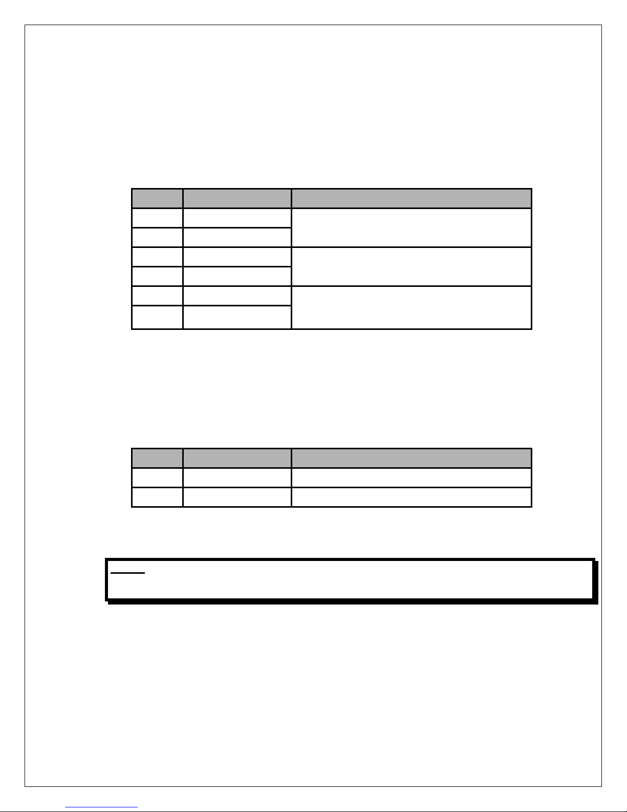
1.1.1 Power Supply Requirements
Single Phase
Line Voltage 200Vac-240Vac, +/-10%, 1 Phase, 35 Amps
Line Frequency 50/60 Hz.
In Rush Current 50 Amps, Maximum
Standby Current 1 Amp
WARNING: The PMX generator can provide power that can damage the X-Ray tube. The user is
responsible for limiting the maximum exposure values to within the ratings of the X-Ray
tube. Spellman is not liable for any damage to the X-Ray tube by the misuse of the PMX
X-Ray generator.
The following table defines the power line requirements for the generators.
NOTE: THE FOLLOWING TABLE CONTAINS RECOMMENDED VALUES FOR THE WIRE SIZES
BETWEEN THE MAINS DISCONNECT AND THE GENERATOR. THE ACTUAL VALUES USED AT
AN INSTALLATION ARE DEPENDENT ON THE QUALITY OF THE INPUT LINE (VOLTAGE
LEVEL) THE CURRENT REQUIREMENTS AND THE LENGTH OF THE CABLE RUN AND MUST
BE CONFIRMED BY THE INSTALLER.
ALL THE RATINGS LISTED CONSIDER THE GENERATOR REQUIREMENTS ONLY. THE
INSTALLER MUST MAKE THE NECESSARY COMPENSATION FOR ADDITIONAL LOAD
REQUIREMENTS
A POOR QUALITY INPUT LINE MAY RESULT IN THE INSTALLER HAVING TO
DERATE THE GENERATOR'S MAXIMUM POWER
Mains
Voltage
220 Vac
Minimum
Recommended
Mains
Disconnect
to Generator
15 ft./5 m max)
#10
2
(6 mm
)
• External EMC Filter (required to meet
CE/EMC specifications) – Not provided with
the generator. Custom er is responsible f or
providing the external filter as needed;
Schaffner FN2070-08-36A type EMI filter or
equivalent one recommended.
PMX MANUAL 3 118164-001 REV. A
Generator
In Rush Line
Current
50 A 35 A #10
Minimum
Recommended
Generator
Service Rating
• Mains Contactor - Not provided within the
generator. Customer is responsible for
mains safety disconnection.
Minimum
Recommended
Ground
Wire
Size
2
(6 mm
)
Apparent
Mains
Resistance
0.06 Ω
Page 9
Operating Temperature
10 to 40 °C (50 to 104 °F).
Relative Humidity
20 to 85%, non-condensing.
Atmospheric pressure range
500 to 1060 hPa (375 to 795 mm Hg).
TRANSPORT AND STORAGE
Ambient temperature range
-40 to 85 °C (-40 to 185 °F).
Relative humidity
5 to 95%, non-condensing.
Atmospheric pressure range
500 to 1060 hPa (375 to 795 mm Hg).
1.1.2 Environment Requirements
Operating Environment
1.2 THEORY OF OPERATION
1.2.1 Function Overview
The PMX X-Ray generator utilizes sophisticated
power conversion technology. A variety of
analog, digital and switching pow er conversion
techniques are used throughout.
The PMX generator is basically an AC to DC
power converter. Within the generator,
conversions of AC to DC, then to high frequency
AC, then to high voltage DC take place. By
reviewing further the sub-assemblies, a basic
understanding of the process can be gained.
1.2.2 Line Rectification and Filtering
Basic AC line rectification provides the DC buss
voltage for the high voltage inverter, Anode
rotor drive, and the filament supply.
The input line voltage can vary from 180V up to
264V within the series.
The line voltage is connected directly to the EMI
filter. The EMI filter reduces conducted HF noise
on the AC mains. The output of the EMI f ilter is
connected to an off line auxiliary power inverter
circuit that provides 2 4V power for gener ating
other auxiliary supply DC voltages.
1.2.3 Inverter
The inverter is a “half -bridg e” topolog y. Cur rent
mode control is used for driving the inverter. An
IGBT power module employed. The IGBT
provides high frequency switching to control the
primary current flow to the high voltage
transformer.
Circuits on the Power PCB board provide the
gate control of the IGBT switches. The system
control board generates gate drive control
signals. The circuits on t he Po wer PC B pro vi de
the required gate voltages and off s ets .
1.2.4 High Voltage Transformer
The output of the High Frequency Quasiresonant Inverter is connected to the primary of
the High Voltage Transformer. The High
Voltage Transform er is a step up type. T ypical
secondary output voltage is in the range of
12.5kV depending upon output voltage ratings.
1.2.5 High Voltage Assembly
The High Voltage Assembly will vary depending
upon the model ord ered. The circu itry typically
consists of an arrangement of half wave voltage
doubler.
A high bandwidth resistive/capacitive divider
provides voltage feedback for regulation and
monitoring. A sense resistor connected at the
low voltage end of the High Voltage Multiplier
circuit pro vides current feedback for regulation
and monitoring.
1.2.6 System Control PWB
Auxiliary DC voltages are generated in the low
voltage power supply section of the System
Control PWB.
PMX MANUAL 4 118164-001 REV. A
Page 10
LEDs provide status diagnostics needed for
recognizing the operation/shutdown mode of
the generator.
A precision +10Vdc reference is generated on
the control PCB for programming kV, mA and
other references.
Control of the generator utilizes sophisticated
analog and digital circuitr y resulting in fast and
accurate control, protection and communication
interfacing.
This generator is based on advanced quasiresonant PWM control. Analog signals are
digitized in A/D conver ter and pr ocess ed with in
FPGA and DSP circuits to provide maximum
accuracy and reliability.
All feedback signals are sent to the user
interface through digital an d D/A circ uits where
switching is possible between feedback and
program signals. This allows the us er to pres et
the desired output before energizing high
voltage.
All program voltages ar e typically ramped up to
set level by the digital ramp generator.
FPGA and accompanying A-D and D-A
converters and drivers provide system Fault
Control Indicat ion. User interface is proces sed
on this PWB as well, providing isolated relay
coils, opto couplers and open collector contacts.
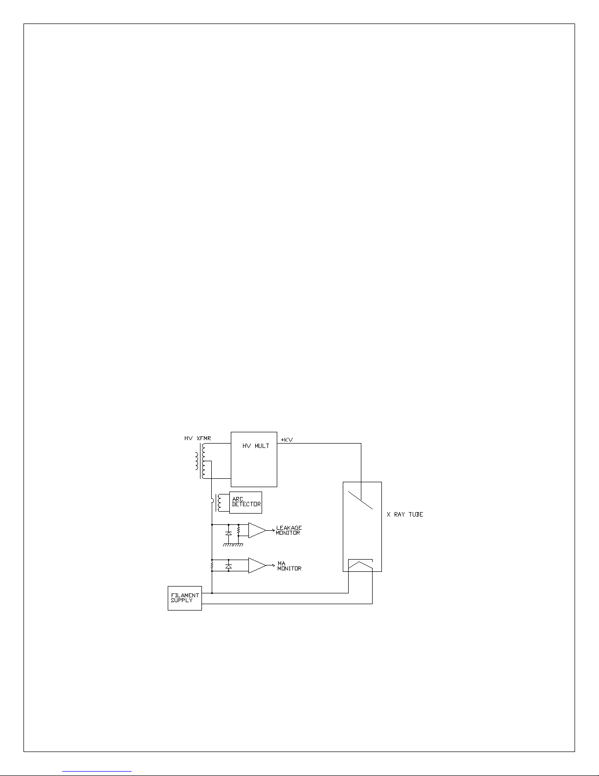
1.2.7 Filament Power Supply
The filament inverter provides the power to drive
the filament winding of the X-Ray tube. The
filament inverter is a high frequency, series
resonant inverter. The inverter provides high
frequency ac current to the primary of the
filament isolation transformer. The filament
isolation transformer secondary is connected to
a full wave rectifier and capacitor f ilter creating
a DC filament. Rela y K4 connects the f ilament
output to TB3 terminals 1 or 3 for small or large
filament respectively as required by the
operator. The filam ent circuitry also provides a
variety of control, diagnostic and protection
functions.
See Figure 1.2 for a simplified diagram of the XRay tube connection and current sensing
circuits. The filament circuitry also provides a
variety of control, diagnostic and protection
functions.
If any abnormal c ondition appears, monitoring
circuitry will shut down the unit indicating the
fault.
Figure 1.2 Simplified schematic of X-Ray tube connection
PMX 5 118164-001 REV. A
Page 11

1.2.8 High Speed Starter
The rotating anode is powered and controlled
by the action of a split-phase t ype of induction
motor circuits in the PMX generator. The
rotating anode has considerable mass to
dissipate the heat generated by the beam
current, and subse quently requires some tim e
to accelerate to its norm al operat ing sp eed. T o
reduce this time, the “h igh s peed s tart er ” cir cuit
in the PMX applies a series of “boost” steps
consisting of different frequencies and
increased voltage during the boost cycle to
increase the accelerati on of the anode rotat ion
to operating speed within several seconds.
Following the boost cycle, the applied voltage is
reduced to proper vo ltage to maintain ro tation.
There are two operati ng modes for the anode
rotor: low speed (60Hz stator voltage), and high
speed (180Hz stator voltage). These are
selected by the operator depending on the
requirements of the application.
The PMX is equipped with safety interlock s for
user personnel and equipment protection. An
open interlock circuit inhibits operation of the
PMX generator.
PMX MANUAL 6 118164-001 REV. A
Page 12
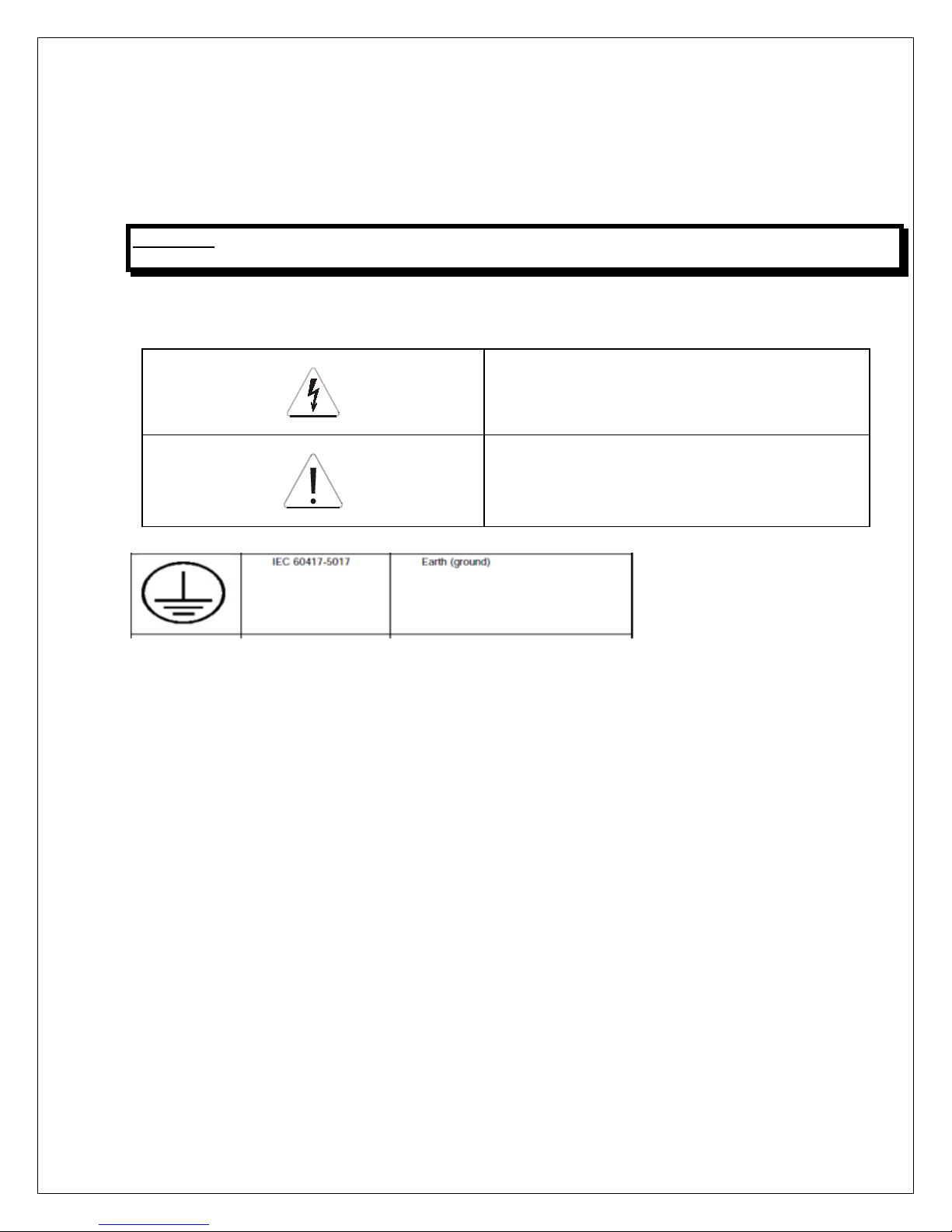
High voltage symbol use d to indic ate the pres ence of
Warning symbol used to indicate a potential hazard to
1.3 SAFETY
1.3.1 Safety and Warning Symbols
WARNING: THIS X-Ray UNIT MAY BE DANGEROUS TO OPERATOR UNLESS SAFE EXPOSURE
FACTORS AND OPERATING INSTRUCTIONS ARE OBSERVED.
The following advisory symbols are used on the safety warning labels, and/or on circuit boards.
high voltage.
operators, service personnel or to the equipment.
PMX MANUAL 7 118164-001 REV. A
Page 13
CHAPTER 2
INSTALLATION
2.1 INTRODUCTION
This chapter contains instructions for
unpacking, positionin g, and cabl ing the PMX
generator, allowing for initial power-up and
exposures.
2.2 UNPACKING
WARNING: THE GENERATOR
WEIGHS APPROXIMATELY
23 POUNDS (10.5KG).
1. Inspect the package exterior for
evidence of dam age du e to handling
in transit. Notify the carrier and
Spellman immediately if damage is
evident. Do not destroy or remove
any of the packing material used in a
damaged shipment.
2. Remove the cardboard outer
packaging. See the cautionary note
below before removing the
packaging.
CAUTION: OPEN THE CARDBOARD
PACKAGING CAREFULLY. SHARP TOOLS MAY
DAMAGE THE CONTENTS.
3. Set aside the cardboard packaging.
4. After unpacking, inspect for visible
damage.
5. Keep the shipping containers. In
case of shipping dam age, place the
unit(s) back in its s hipping pack and
notify the carrier and the Customer
Support Department as indicated in
this manual.
2.3 OVERALL CONNECTIONS
NOTE: THIS IS BASIC CONNECTION
ILLUSTRATION FOR TESTING. MORE
COMPLEX AND DEDICATED CIRCUITRY
IS NEEDED IN THE FINAL APPLICATION.
All cables should be route d away from high
voltage areas, and dressed and secured
neatly in place. Cables s hould be cut to the
correct length if possible as excess cabling
may contribute to EMI/RFI problems. For
those cables that cannot be cut to the correct
length (HV cables and console cables for
example), try to minimize the area inside any
loops of excess cable, as t hese loops are in
effect an antenna.
PMX MANUAL 8 118164-001 REV. A
Page 14
PMX MANUAL 9 118164-001 REV. A
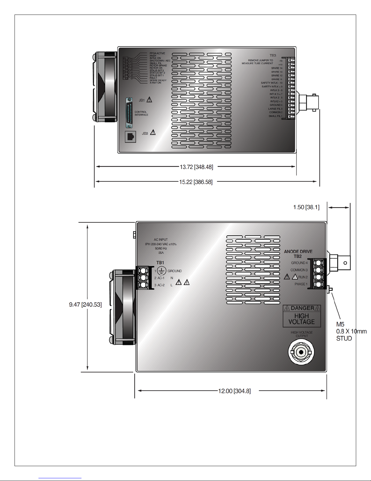
Figure 2-1: PMX I/O and indicator locations
Page 15
TB1
1.GROUND
2.AC-1
3.AC-2
JB1
CONTROL
INTERFACE
TB3
TB2
ANODE DRIVE
FILAMENT DRIVE
HIGH VOLTAGE
OUTPUT
JB3
ETHERNET
1
2
3
4
5
6
7
8
9
10
11
12
13
14
15
16
1
2
3
4
GROUND STUD
SYSTEM INTERLOCK
FILTER
N
L
PE
mA TEST PINS
FUSE CONTACTOR
INTERFACE
CABLE
SYSTEM INTERFACE
(OPTIONAL)
X-RAY TUBE
HV CABLE
VMX GENERATOR
POWER LINE
LV CABLE
INTERLOCK
SHORT THE WIREPAIR IF
SYSTEM INTERLOCK NOT
AVAILABLE
INTERLOCK WIRE
USER SUPPLIED COMPONENT
NOTE:
2.4 POWER LINE MAINS
WARNING: MAIN CONTACTOR IS NOT
PROVIDED WITHI N TH E G EN ER A TO R ,
CUSTOMER IS RESPONSIBLE FOR MAINS
SAFETY DISCONNECTION.
PMX MANUAL 10 118164-001 REV. A
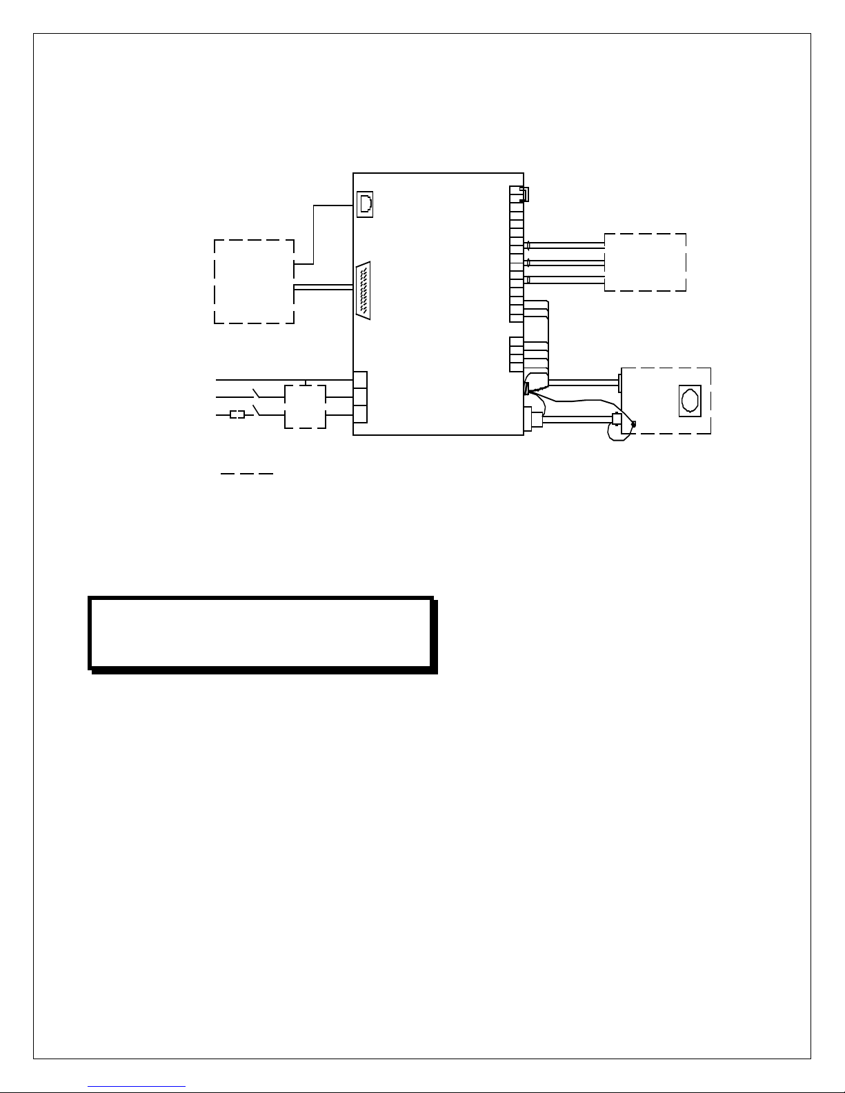
Figure 2-2: Overall connection
The PMX supply does not contain power
line current limiting or fuses. It is strongly
recommended that the user provide fuses
or circuit breaker protection on the input
power lines to limit fault current that may
occur due to component failure, or
operator error. Fuses or circuit breake rs
with current rating of 35 Amps are
recommended
Refer to Chapter 1 for generator po wer and
generator power line requirements.
1. Check the input voltage rating on the
nameplate of the supply and make
certain that this is the rating of the
power source to be connected.
2. Units operate on 200V-240VAC, +/-
3. A three-wire terminal block (TB1) is
4. DO NOT SWITCH ON MAINS
2.5 Cable connection illustration
2.5.1 HV Cable Connection
The X-Ray tube should be mounted in its
1. Verify that the HV cable terminations
2. Be sure that the rubber expansion
10%, 50/60Hz, single phase 35A.
provided for connecting to the AC
supply (refer to Figure 2-2).
POWER AT THIS TIME.
normal fixture i.e. tube stand or other
device.
are clean and in good condition.
ring is located at the bottom of the HV
cable plug.
Page 16

3. Connect HV cable to the CA3 type
high voltage output terminal at rear of
the unit.
4. Connect the other side of HV c able
to the corresponding HV te rminal on
tube housing.
5. Connect the cable shield wire
accompanying HV c able to the PMX
ground stud and tube housing
separately.
2.5.2 Stator Cable Connection
Refer to Table 2-1 for the X-Ray tube stator
connections.
1. Tube low voltage cable is a hybrid
one with filament and stator drive
wire bundled together. Tube side
should be standard terminal style,
while generator side is unterminated.
Customer should term inate the wire
with suitable terminal.
2. Connect wires from the X-Ray tube
housing low voltage connector stator
pins to PMX terminal block TB2
terminals 1 (stator PHASE), 2 (stator
RUN), 3 (stator COM), and 4
(GROUND).
3. Connect tube thermal switch wires to
TB3-5 and TB3-6 if present. If not,
short the two pins. Normally, there
are no such separate wires for
MAMMO tubes; it is always
integrated into the three phase line.
Refer to tube hous ing dat a sheet for
specific information.
2.5.3 Filament Driver Cable Connection
1. Filament driver cable has three wires
and bundled together with stator
wires within same cable. Customer
should terminate the wire with
suitable terminals and lea ve enough
length to reach the terminal TB3.
2. Connect wires from the X-Ray tube
housing low voltage connector
filament pins to PMX terminal block
TB3 terminals 1 (FIL Small), 2 (FIL
COM), and 3 (FIL Large).
PMX MANUAL 11 118164-001 REV. A
Page 17
Pin #
Definition
Description
TB3-1
SMALL FIL
To tube small filament.
TB3-2
COMMON
To tube filament common.
TB3-3
LARGE FIL
To tube large filament.
Pin #
Definition
Description
JB1-1
GND
Generator signal groun d for referenc e of interface
JB1-2
(+) 5VDC Out
5 volts DC from generator for use in powering
such as optocouplers. 100mA
maximum.
JB1-3
RS232 Tx Out
RS232 Transmit (out) from generator
JB1-4
RS232 Rx In
RS232 Receive (in) to generator
JB1-5
PREP
User Signal (Contact Closure) to alert the
this signal is active, exposure parameters are
enables the starter to boost the rotor. Contact
JB1-6
READY
Generator Signal to user to indicate the rotor r uns
JB1-7
ROTOR SHUTDOWN
User Signal to generator to brake the rotor drive off.
JB1-8
EXPOSURE
User Signal (Contact Closure) to generator to
Voltage is generated after the boost time.
pin 24. Closed=Exposure.
Table 2-2. Pin layout of filament driver connector.
2.6 MULTI INTERFACE CABLE
CONNECTIONS
The PMX has multi interface connections
include digital I/O, serial communication, and
interlock. Operator m ust verify and connect
every signal properly though some of them
are optional, before initiating power-up and
basic test.
The interlock, serial communication and
exposure buttons interface shall be made
available via a multi signal cable. Refer to *-*
for a schematic of isolation and signal
direction.
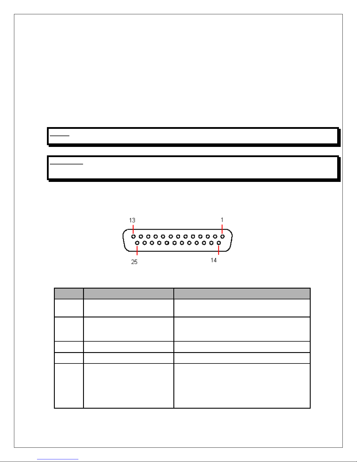
2.6.1 Pin Layout of the Multi interface
The multi signal interface shall have a female
25 pin D-Sub (JB1) on the PMX. Twisted
pairs shall be used where applicable. The pin
layout is giv en in Table 2-3.
circuits
interface circuitry
generator that exposure sequence will begin. Once
locked in and cann ot be changed. The gener ator
connection to pin 24. Closed = PREP.
to speed and the generator is ready for X-Ray
exposure. Transistor output. Low/Active=Ready
Low brakes Rotor. (Open wil l not restart rot or until
a new PREP cycle is started). Reference to GND.
generate X-Rays. Filament is boosted, and High
PMX MANUAL 12 118164-001 REV. A
(Approximately 1 second). Contact connection to
Page 18

JB1-9
X-Ray ON 75% Status
Transistor output to indicate X-Ray ON status.
Status Synchronize with 75% kV setting point.
JB1-10
X-Ray ON Status
Transistor output to indicate HV ON status.
Synchronize with HV start-up.
JB1-11
N/C
Not Used
JB1-12
X-Ray SHUTDOWN/AEC
User Signal to generator to rapidly turn HV OFF
Reference to
GND. LOW Shuts down HV.
JB1-13
RS232 ISO Ground
Isolated ground from the isolated RS232
transceiver I.C.
JB1-14
HVG FAULT Status
Generator signal indicating generator fault. Open
collector transistor output. Lo w/Ac ti ve =Fau lt
JB1-15
Status Bit 1
3 bit status lines f or up to 6 status m essages . See
functionality. Open Collector transistor output.
JB1-16
Status Bit 2
JB1-17
Status Bit 3
JB1-18
N/C
N/C
JB1-19
N/C
N/C
JB1-20
kV Monitor
Signal from generator. 0-10V=0-50kV. Zout=1K
ohm
JB1-21
Emission Monitor
Signal from generator. 0-10V=0-200m A. Zout=1K
ohm
JB1-22
Filament Current Monitor
Signal from generator. 0-10V=0-6A. Zout=1K ohm
JB1-23
Program/Monitor Return
Ground for reference of program and monitor
signals
JB1-24
+24VDC Out
For connection to P REP and EXPOSURE control
relay coils.
JB1-25
SHIELD/GND
For connection of interface cable shield to
generator chassis ground.
(Reference to GND). High/Active=X-Ray ON
(Reference to GND). High/Active=HV ON Status.
and ON during Exposure. (AEC).
separate matrix (Table 2-4) describing
Low/Active=Message.
Table 2-3 Pin layout of multi signal connector
Refer to chapter 3 for detailed requirements and function descriptions.
PMX MANUAL 13 118164-001 REV. A
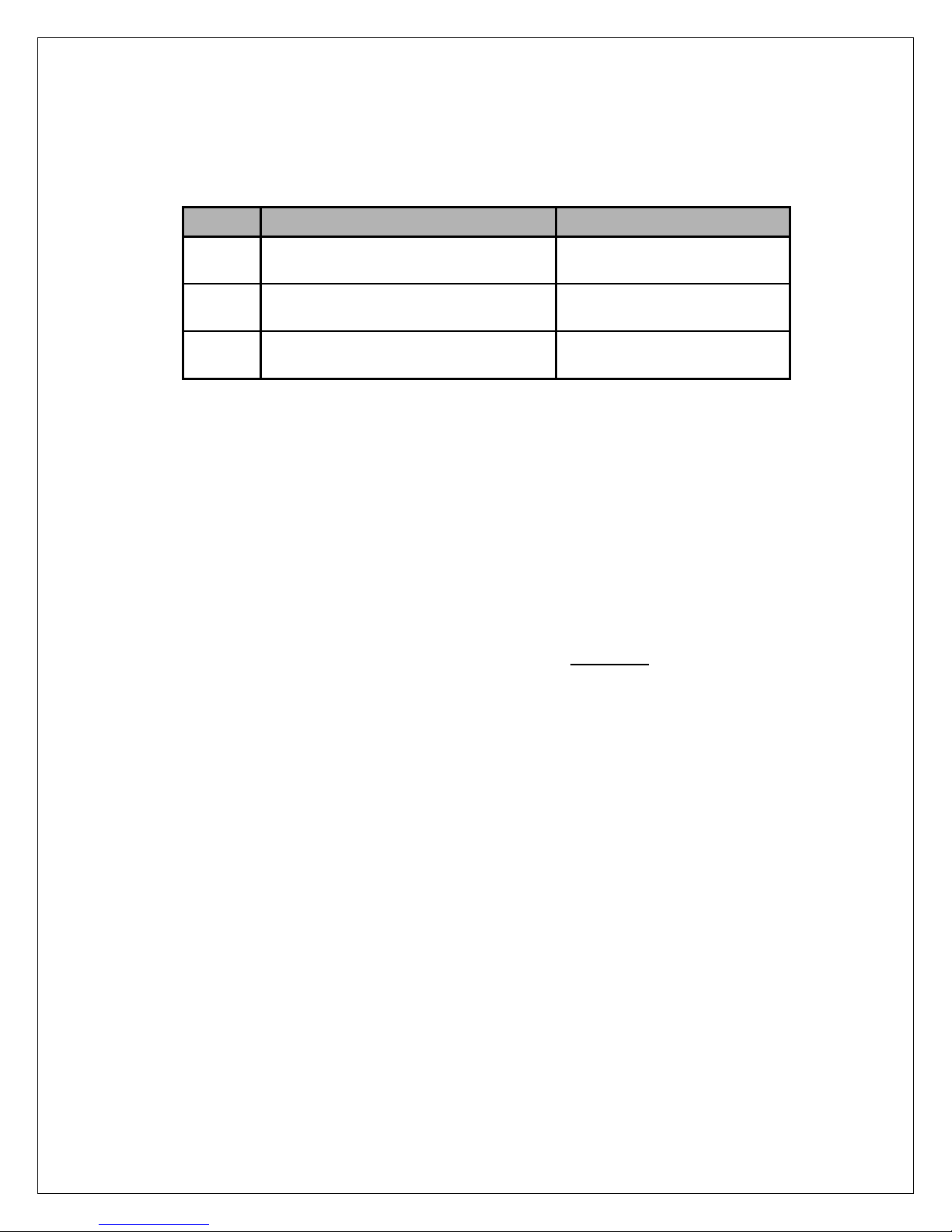
Page 19
Pin #
Definition
Description
TB3-5
Interlock 2 +
Used if tube has separate thermostat switch.
TB3-6
Interlock 2 -
TB3-7
Interlock 3 +
Used if tube has cooling circulator flow switch.
TB3-8
Interlock 3 -
TB3-9
Safety Interlock+
User signal (Contact Closure) f or safety interlock s
HV OFF, or
TB3-10
Safety Interlock-
Pin #
Definition
Description
TB3-15
Tube current +
Tube current flows out from this pin.
TB3-16
Tube current -
Tube current flows into this pin.
2.7 Interlock Connections
Interlock connections are provided for a
variety of safety functions such as room door
interlock, separate thermal switch interlock,
tube flow switch interlock. The unit will not
operate unless the interlocks are closed.
2.8 Tube Current Monitor Connection
Tube current test pins are provided for
monitoring the actual tube current (mA) if
needed. Normally, a jumper is installed to
short the two pins (refer to Figure 2-2).
The pin definition shows below:
Opening the interlock circuit will cause the
unit to shut off.
Three safety interlocks are located in TB3 for
system interlock purpose. Short the terminals
if not used.
The pin definition shows below:
Open=over temp. (Short terminals if not used).
Open=no flow. (Short terminals if not used).
such as door interlocks. Open turns
inhibits HV from being generated.
Remove the jumper and install the current
meter in series to monitor the actual tube
current.
Two test pins are located in TB3 (TB3-15,
TB3-16). Short the two pins if not used.
2.9 GROUND CONNECTION
NOTE: THE INSTALLER SHOULD ENSURE THAT ALL CABLE CONNECTIONS TO THE GENERATOR
ARE SECURE, AND ALL CABLES EXTERNAL TO THE GENERATOR ARE
ADEQUATELY PROTECTED AGAINST ACCIDENTAL DISCONNECTION.
2.9.1 X-Ray Tube Housing Ground
A separate ground wire (10 AWG, 6mm
must be connected from the X-Ray tube
housing to the ground stud on the r ear of the
PMX chassis. These ground locations may
have other ground wires already connected;
PMX MANUAL 14 118164-001 REV. A
ensure that these existing ground wires are
not disconnected when making the X-Ray
2
)
tube ground connection.
Failure to make this groun d connection may
result in intermittent operation and/or
exposure errors or even worse IGBT failure.
Page 20
2.9.2 Chassis Ground
The chassis of the P MX generator m ust be
grounded to the local earth grou nd and also
to the tube housing groun d. See Figure 2-2
for typical operating setup. A three-wire
terminal block is provided for connecting to
the AC supply.
2.10 FINAL CHECKS
NOTE: THE INSTALLER SHOULD ENSURE THAT ALL CABLE CONNECTIONS TO THE
GENERATOR ARE SECURE, AND ALL CABLES EXTERNAL TO THE GENERATOR ARE
ADEQUATELY PROTECTED AGAINST ACCIDENTAL DISCONNECTION.
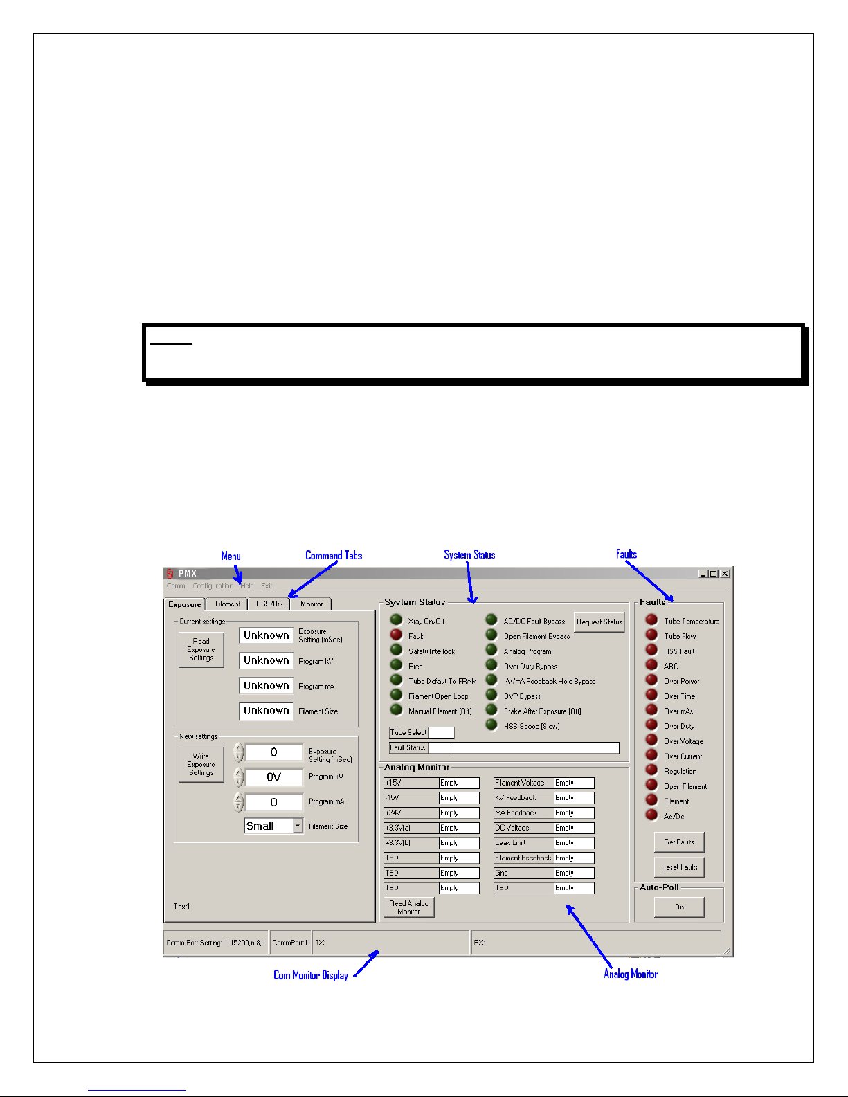
2.11 GUI SOFTWARE
The optional GUI utility software allows for
data communication between the generator
and an external computer. This provides a
“virtual console” with which user can release
all the command defined in the protocol and
verifies all the functions independently before
The room interface c onnect ions m ay now be
completed. Before power on, user needs to
check the items as below finally.
• When finished all wiring, check that all
connections are tight and secure.
• Double check the breaker, EMC filter,
fuses, etc. User is res ponsible f or on t he
main input power lines.
• Check that all cables are dressed neatl y
outside the cabinet, and secured as
necessary.
• Check the ground connection again.
integrating the generator into their ultimate
system.
The GUI consists of the Analog Monitor
Section, the System Status Section, the Fault
Section, the Command Tab Section, the Com
Monitor Display, and the Menu.
PMX MANUAL 15 118164-001 REV. A
Page 21

The Command Tab section, along with the
Monitor / Status / Fault sections provide
access to the various com mands defined in
the PMX Protocol Spec. The Analog Monitor,
System Status, and Fault sections are always
visible and can be accessed at any time. The
Command Tab section provides access to
function. Clicking on the tabs at the top of the
Command Tab section selects a particular
group of commands. Only one group (tab)
can be selected at any one time.
See separate docum ent for t he detaile d GUI
instruction.
other commands grouped together by
PMX MANUAL 16 118164-001 REV. A
Page 22
Pin #
Definition
Description
JB1-1
GND
Generator signal groun d for referenc e of interface
JB1-2
+5VDC Out
5 volts DC from generator for use in powering
. 100mA
JB1-3
RS232 Tx Out
RS232 Transmit (out) from generator
JB1-4
RS232 Rx In
RS232 Receive (in) to generator
JB1-5
PREP
User Signal (Contact Closure) to alert the
this signal is active, exposure parameters are
enables the starter to boost the rotor. Contact
CHAPTER 3
INTERFACING
3.1 introduction
This chapter describes the interfacing of the
PMX generator to the customer s ystem control
side, especially with th e serial communication,
3.2 MULTI INTERFACE
NOTE: THE INSTALLER MUST PROVIDE THE NECESSARY INTERFACING CABLES FOR WIRING TO THE
GENERATOR INPUTS AND OUTPUTS DESCRIBED IN THIS SECTION.
WARNING: LINE VOLTAGE IS PRESENT INSIDE THE GENERATOR AT ALL TIMES THAT THE MAIN
DISCONNECT IS SWITCHED ON. FOR SAFETY, THE MAIN DISCONNECT SHOULD BE
SWITCHED OFF AND LOCKED OUT WHILE CONNECTING ROOM EQUIPMENT.
3.2.1 Connector Style and Pin Layout
exposure control switch. Also, exposure mode
is introduced with the timing sequence
described as well.
Figure 3-1 multi signal interface connector
PMX MANUAL 17 118164-001 REV. A
circuits
interface circuitry such as opto couplers
maximum.
generator that exposure sequence will begin. Once
locked in and cann ot be changed. The gener ator
connection to pin 24. Closed = PREP.
Page 23

JB1-6
READY
Generator Signal to user to indicate the rotor r uns
JB1-7
ROTOR SHUTDOWN
User Signal to generator to brake the rotor drive off.
JB1-8
EXPOSURE
User Signal (Contact Closure) to generator to
pin 24. Closed=Exposure.
JB1-9
X-Ray ON 75% Status
Transistor output to indicate X-Ray ON status.
Ray ON
Status Synchronize with 75% kV setting point.
JB1-10
X-Ray ON Status
Transistor output to indicate HV ON status.
Synchronize with HV start-up.
JB1-11
N/C
Not Used
JB1-12
X-Ray SHUTDOWN/AEC
User Signal to generator to rapidly turn HV OFF
Reference to
GND. LOW Shuts down HV.
JB1-13
RS232 ISO Ground
Isolated ground from the isolated RS232
transceiver I.C.
JB1-14
HVG FAULT Status
Generator signal indicating generator fault. Open
collector transistor output. Lo w/Ac ti ve =Fau lt
JB1-15
Status Bit 1
3 bit status lines f or up to 6 status m essages . See
functionality. Open Collector transistor output.
JB1-16
Status Bit 2
JB1-17
Status Bit 3
JB1-18
N/C
N/C
JB1-19
N/C
N/C
JB1-20
kV Monitor
Signal from generator. 0-10V=0-50kV. Zout=1K
ohm
JB1-21
Emission Monitor
Signal from generator. 0-10V=0-200m A. Zout=1K
ohm
JB1-22
Filament Current Monitor
Signal from generator. 0-10V=0-6A. Zout=1K ohm
JB1-23
Program/Monitor return
Ground for reference of program and monitor
signals.
JB1-24
+24Vdc Out
For connection to P REP and EXPOSURE control
relay coils.
JB1-25
SHIELD/GND
For connection of interface cable shield to
generator chassis ground
to speed and the generator is ready for X-Ray
exposure. Transistor output. Low/Active=Ready
Low brakes Rotor. (Open wil l not restart rot or until
a new PREP cycle is started). Reference to GND.
generate X-Rays. Filament is boosted, and High
Voltage is generated after the boost time.
(Approximately 1 second). Contact connection to
(Reference to GND). High/Active=X-
(Reference to GND). High/Active=HV ON Status.
and ON during Exposure. (AEC).
Table 3-2 Pin layout of multi signal interface
3.2.2 Serial Communication Interface
separate matrix (Table 2-4) describing
Low/Active=Message.
PMX MANUAL 18 118164-001 REV. A
Page 24
Pin #
Definition
Description
JB1-3
RS232 Tx
RS232 Transmit (out) from
JB1-4
RS232 Rx
RS232 Receive (in) to
JB1-13
RS232 ISO Ground
Isolated ground from the
The serial communication is part of the Multi
Signal Interface (JB1).
The pin definition shows below:
User should connect the R S232 cable properl y
with system side such as PC. Twisted wires are
preferable to enhance the EMC performance.
GUI software can be used temporarily to test the
PMX provided installed on the user PC. (Ref er
to separate document for detailed information of
GUI). But user need to develop their own
ultimate software based on open protocol
(Refer to separate document) and design
system control board to integrated PMX into
their system with proper method (Refer to 2.6.1
NOTE the isolation requirement).
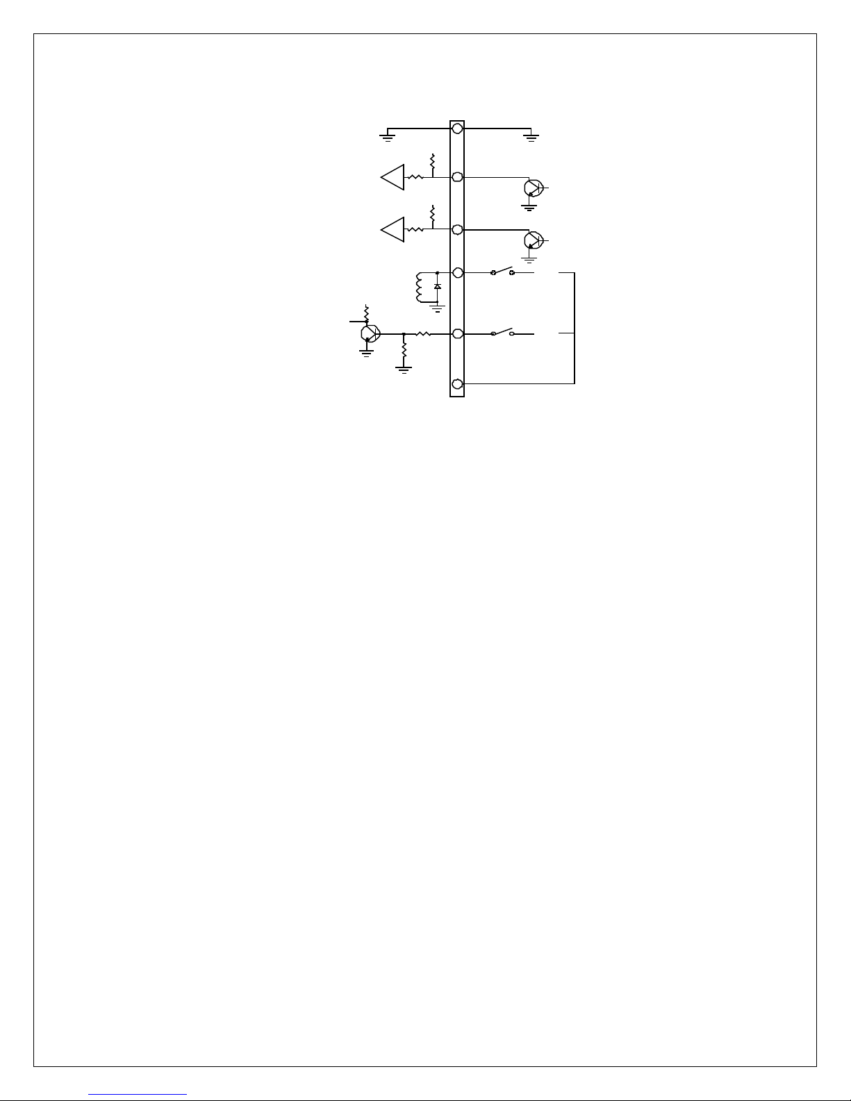
3.2.3 Digital I/O Control Interface
Remote digital control of the PREP, ROTOR
SHUTDOWN, EXPOSURE, X-Ray
SHUTDOWN, are available on the 25-pin I/O
connector for maintenance. All of these controls
except PREP and EXPOSURE are toggle on/off
type signals. PREP and EXPOSURE are
The RS232 communic ation interface has been
isolated inside t he HVG with specific IC.
generator
generator
isolated RS232 transceiver I.C .
controlled by a momentary normally open
contact. If remote control is required, the remote
interface dummy plug must be removed and
replaced with the appropriate remote circuits.
See Figure 3-2 for recommended interface
circuits.
In order to eliminate sig nal bounce caused
by mechanical contact, an el ectron ic sw itch
such as opto coupler device is
recommended for these signals.
Warning: Max current that the +24Vdc
supply can provide is 100mA.
PMX MANUAL 19 118164-001 REV. A
Page 25
JB1
Customer Interface
High Voltage
power supply
1
7
12
5
8
+5V
10K
Transistor On =
Rotor shutdown
+5V
10K
Transistor On =
X-ray OFF
+24V
Switch closed
for PREP
+24V
Switch closed
for EXPOSURE
NOTES:
Relay coil Z=178
Ω
+5V
24
+24V
3.2.4 Remote Status Interface
Remote status signals f or KV MIN tube curren t
limit, tube power limit, overvoltage, and filament
Figure 3-3 for recommended interface circuits.
Figure 3-2 Digital I/O Control Interface
Current limit, over temperature, and power
supply fault is provided.
These signals are open collector type.
(Normally off), and are intended to drive the
diode of an opto-coupler.
PMX MANUAL 20 118141-002 REV
Page 26

JB1
Customer Interface
Generator interface
6
9
NOTES:
50mA max collector current on internal power supply transistors
+5V
330
100
+5V
1K
100
+5V
1K
100
10
+5V
330
100
+5V
330
100
+5V
330
100
+5V
330
100
READY
X-RAY ON Status
HV ON Status
14
HVG FAULT Status
15
BIT1 Status
16
BIT2 Status
17
BIT3 Status
LOW=READY
HIGH=X-RAY 75% ON
HIGH=X-RAY ON
HIGH=FAULT
LOW=ACTIVE
LOW=ACTIVE
LOW=ACTIVE
BIT1
BIT2
BIT3
MESSAGE
high
high
high
No Messages
low
high
high
Tube Temp/Flow Fault/HSS Fault
high
low
high
Arc Detected/Shutdown
high
high
low
Over Load: Power/MAS/Time/Duty
low
low
high
Over Voltage/Over Current/Regulation error
low
low
low
Open Filament/Filament Fault
Figure 3-3 Remote status interface
If a fault occurs, the power supply will shut down
and a 3 bit binary code will be gen erate d at the
user interface connector J B1. T o res et, use the
reset function on remote user interface.
Table 3-3 status messages matrix
The fault inf orm ation is provided with three bits
code. Below is the information list.
More than one fault is defined with one code
combination. Use can get specific fault
information by serial command.
PMX MANUAL 21 118164-001 REV. A
Page 27
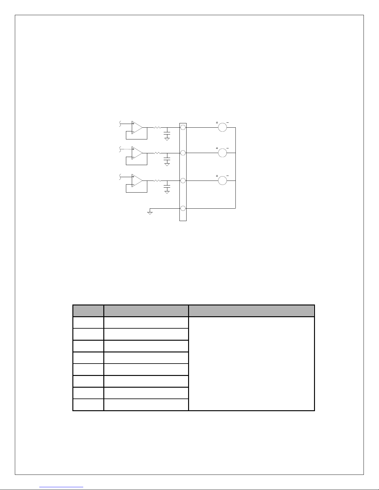
JB1
Generator side
22
Customer side
20
21
1K
0.1
1K
0.1
1K
0.1
23
M
M
M
kV monitor
mA monitor
Filament
monitor
Monitor return
NOTES:
1) Metering circuit should be high Z type(>10Meg)for accurat e measurement.
2) All signals 0-10Vdc = 0-100 % of specified maximum outputs .
Pin #
Definition
Description
JB3-1
TX+ White/Orange
JB3-2
TX- Orange
JB3-3
RX+ White/Green
JB3-4
POE V+ blue
JB3-5
POE V+ blue/white
JB3-6
RX- Green
JB3-7
POE V- brown/white
JB3-8
POE V- brown
3.2.5 Rem ote Monitoring Interface
Test points are made available at the 25-pin I/O
connector from monitoring tube voltage, tube
current and tube filament current. The test
Figure 3-4 for wiring diagram and specifications for remote monitor interface.
points are always positive regardless of the
output polarity, where 0 to 10V = 0-100% of
output. Accuracy is within ±0.5%. All test points
have output impedance of 1Kohm.
Figure 3-4 Remote monitoring interface
3.3 ETHERNET INTERFACE
Ethernet is an optional serial communication
interface with separate standard RJ45 style
RJ45 pin definition shows below:
connector. JB3 is terminal number.
10/100 Base-T Ethernet Interface
PMX MANUAL 22 118164-001 REV. A
Page 28
CHAPTER 4 CONFIGURATION,
CALIBRATION AND OPERATION
4.1 INTRODUCTION
This chapter describes the procedure for
configuring the tube type, configuring user
WARNING: USE EXTREME CARE IN MEASURING HIGH VOLTAGES. ACCIDENTAL CO NTACT
MAY CAUSE SERIOUS INJURY OR DEATH.
MAINS VOLTAGE WILL BE PRESENT INS IDE THE GENERATOR CHASSIS, EVEN
WITH THE POWER SWITCHED OFF. THIS VOLTAGE IS EXTREMELY DANGEROUS,
USE EXTREME CAUTION.
THE DC BUS CAPACITORS, LOCATED ON THE DC BUS ASSEMBLY, PRE SENT A
HAZARD FOR A MINIMUM OF 5 MINUTES AFTER THE GENERATOR HAS BEEN
SWITCHED OFF. CHECK THAT THESE CAPACITORS ARE DISCHARGED BEFORE
TOUCHING ANY PARTS IN THE GENERATOR.
allowed dual speed starter data and
operating filament auto-calibration.
WARNING: THE PROCEDURES IN THIS CHAPTER REQUIRE THE PRODUCTION OF X-Rays.
TAKE ALL APPROPRIATE SAFETY PRECAUTIONS TO PROTECT PERSONNEL
FROM X-Ray RADIATION.
WARNING: ALWAYS ENSURE THAT THE EQUIPMENT UNDER TEST AND ALL ASSOCIATED
TEST EQUIPMENT IS PROPERLY GROUNDED
ENSURE THAT THE HIGH VOLTAGE C ABLES ARE INTACT / UNDAMAGED AND
PROPERLY CONNECTED BEFORE ATTEMPTING EXPOSURES
ENSURE THAT THE PMX IS PROPERLY
INSTALLED AS PER CHAPTER 2 AND
CHAPTER 3 BEFO RE OPER AT I NG W H AT
THIS CHAPTER DESCRIBES.
4.2 TUBE PREHEAT TABLE
CONFIGURATION
The PMX contains up to 2 tube types power
limitation an d filament value tables. Consult
Spellman representati ves when ordering for
available tube tables pre-installed or tube
type field configuration possibility.
Reloading the default preheat tables in the
PMX u nit requires use of the DIP switc hes.
The DIP switches are located near the edge
of the board, to the right of the connector. The
DIP switch identifiers are stenciled on the PC
Board just above the switches, and the
individual switches are numbered at the
bottom of the DIP switch. The figure below
illustrates the DIP switch placement.
PMX MANUAL 23 118164-001 REV. A
Page 29
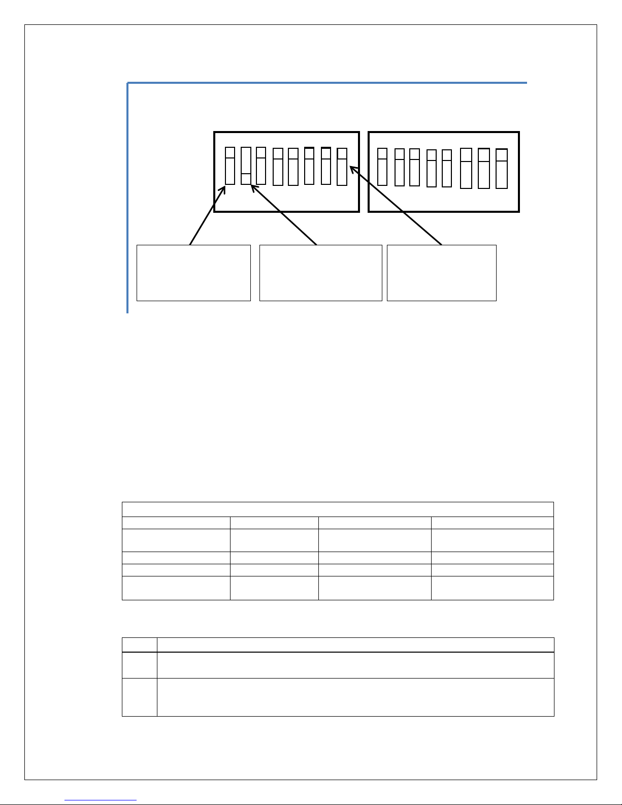
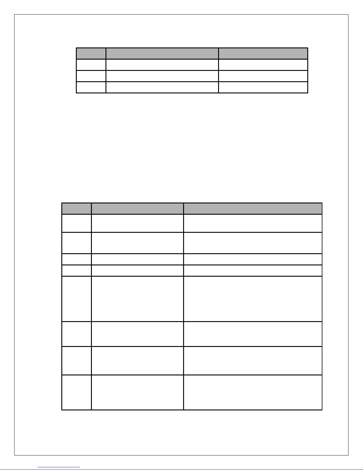
Table 1 -Tube Table Selection Matrix
Tube Selected
Tube number
Switch #1 Position
Switch #2 position
0
(Varian) M113T
3
Down
Up
Invalid Setting (do
not use)
Step
Action
1.
Power down the system, if it is not already powered down. Switch #8 on DIP Switch 1
should be in the up position as show above. This is the normal working position.
2.
Set Switch #8 on Dip Switc h 1 to the down position, th is is with the switch s et toward
#2 on DIP SW1 to the desired tube table as specified in Table 1 above.
1 2 3 4 5 6 7 8
1 2 3 4 5 6 7 8
SW1
SW2
DIP SW1 – Switch
DIP SW1 – Switch #1
DIP SW1 – Switch #2
(Up Position Shown)
Figure 4-1: DIP Switches for Configuration
Switch 8 on DIP SW 1 controls the loading of
the default Tube Table in to FRAM. When the
unit is powered up with this switch in the
down position the sel ected tube def ault data
is loaded in to FRAM, overwriting any current
data, including learned pr eheat values. This
switch only causes tab le up date when it is in
the down position at power up. Setting the
switch to the down position after power up
does not change the tube table.
(Down Position Shown)
#8
(Up Position Shown)
Switch 1 and Switch 2 o n DIP SW 1 select
which tube table wi ll be loaded in to FRAM
and become the active T ube. The setting of
these switches only matters when Switch 8 is
in the Down position at power u p. Changing
the Switch 1 and/or Switch 2 does not change
or reload the tube table if the unit is po wer ed
up with Switch 8 in the up position.
(IAE)XM1016T
Follow the below steps to select the desired table from the pre-installed tube table:
the center of the board (opposite to the above illustration). Also set switch #1 and switch
PMX MANUAL 24 118164-001 REV. A
Up Up
Down Down
Page 30

3.
Turn on the power to the PMX unit, and wait for 10 seconds. This will reload the selected
default table in to the FRAM.
4.
After the 10 seconds has elapsed, turn the power off, and return Switch 8 t o the Up
leave Switch 8 in the Up position.
Step
Action
1.
Entering calibration mode
2.
Enable Prep and Exposure to start calibration
filament will be affected. For example if small filament is calibrated and you attempt to
position. The tables have been reloaded and the system is ready to use. Make sure to
4.3 FILAMENT AUTO-CALIBRATION
The calibration function automatically
establishes calibration curves relating
filament current to tub e cur r ent (mA) at three
or four kV settings, dep ending on generator
type. This allows the g enerator to predic t t he
filament temperature (filament current) that
will be required for any mA value over the full
kV operating range.
It is recommended that the X-Ray tube be
seasoned before att empting auto cal ibrat ion ,
particularly if the tube has not been used for
Sending a “Set Calibration Mode” command (command number 28) with an argument of
1 or 2 or 3 with Prep and Exposure control in the OFF state. Gener ator w ill enter
calibration mode but in ‘pause’ state as the Prep and Exposure is inactive.
Calibration will be starting if both Prep and Exposure are activated. Once the sequence
has started the generator will automatically cycle through the exposure settings as long
as the Prep and Exposure control are ON until it either finishes calibration or there is an
exposure fault.
An exposure fault will cause the calibration routine to abort, and the unit to exit
calibration mode. If the user removes Prep and / or Exposure control during the
sequence, the calibration routine will enter a “Paused” state. It will not exit calibration
mode, but it will stop doing exposures and wait until Prep and Exposure control are both
returned to the ON state. If the user returns Prep and Exposure control ON, the PMX will
continue the calibration. Usually it will continue from where it was when the sequence
was paused, but depending on what it was doing when the calibration sequence was
interrupted it may go back and repeat a previous step.
The user may cancel calibration at any time by first setting Prep and / or exposure
control off, and then sending a “Set Calibration Mode” Command with an argument of 0.
Sending this command resets the calibration sequence. The next time calibration is
started it will go back to the beginning. Once calibration is started previous values for
preheat will be overwritten. Stopping calibration in the middle will result in some points
being calibrated and others not being calibrated. This may result in poor or inconsistent
preheat adjustment.
If user chooses to calibrate large and small filaments separately, only the chosen
some time. Refer to tube datasheet for
seasoning operation.
There are two different modes for user
selection to calibrate filament. User can
calibrate the large filament and small filament
separately or calibrate both large filament
and small filam ent at one t im e. Sendi ng “Set
Calibration Mode” command (command
number 28) with different argument will enter
different calibratio n mode (Refer to protoc ol
specification document for details).
Use these steps to per form the X-Ray tube
auto calibration function:
PMX MANUAL 25 118164-001 REV. A
Page 31

calibrate the large filament, but the calibration fails, it does not affect the small filament
3.
Exiting calibration mode
Step
operation
Action
2.
Presetting
Using the computer interface, select ROTOR SPEED, and
EXPOSURE time (0.5 seconds suggested).
2.
PREP
After presetting desired levels, initiate a PREP command.
PMX internal memory.
3.
READY
After approximatel y 2 seconds, a READ Y status signal will
reset.
4.
EXPOSURE
When READY status is retur ned from the power supp ly, an
set for the
will return to 0 volts until the next PREP/EXPOS URE cycle.
calibration. In this case you would have to rerun the large filament calibration, but not the
small filament calibration.
When calibration pr ocess is finished, Prep and Exposure should be released, and then
sending a “Set Calibr ation Mode” Comm and with an argument of 0 will let the PMX exit
calibration mode.
4.4 OPERATING X-RAY EXPOSURES
4.4.1 Normal Exposure
WARNING: AFTER TURN OFF, DO NOT UNPLUG TH E OUPUT CABLE UNTIL THE INTERNAL
CAPACITANCE IS DISCHARGED (APPROXIMATELY 3 MINUTES).
Use these steps to initiate a normal exposure:
SMALL or LARGE FILAMENT. Set KV (initial setting of
20kV is suggested), mA (10mA suggested), and
This will cause the X-Ray tube anode rotor to start, and apply
filament pre-heat cur rent to the t ube per value s tored in the
be returned to the computer indicating that the anode rotor is
up to speed, and the t ube i s read y to gen erate X -Rays. T h e
READY signal wil l remain for 30 seconds and aut omaticall y
exposure can then be ini tiated. When exposure is i nitiated,
HV is applied to the X -Ray tube and the power supp ly loop
control automaticall y adjusts the filament current to provide
the mA tube current that was previously preduration of the exposure time. Following an exposure, the HV
Below is timing sequence for a typical normal exposure.
PMX MANUAL 26 118164-001 REV. A
Page 32
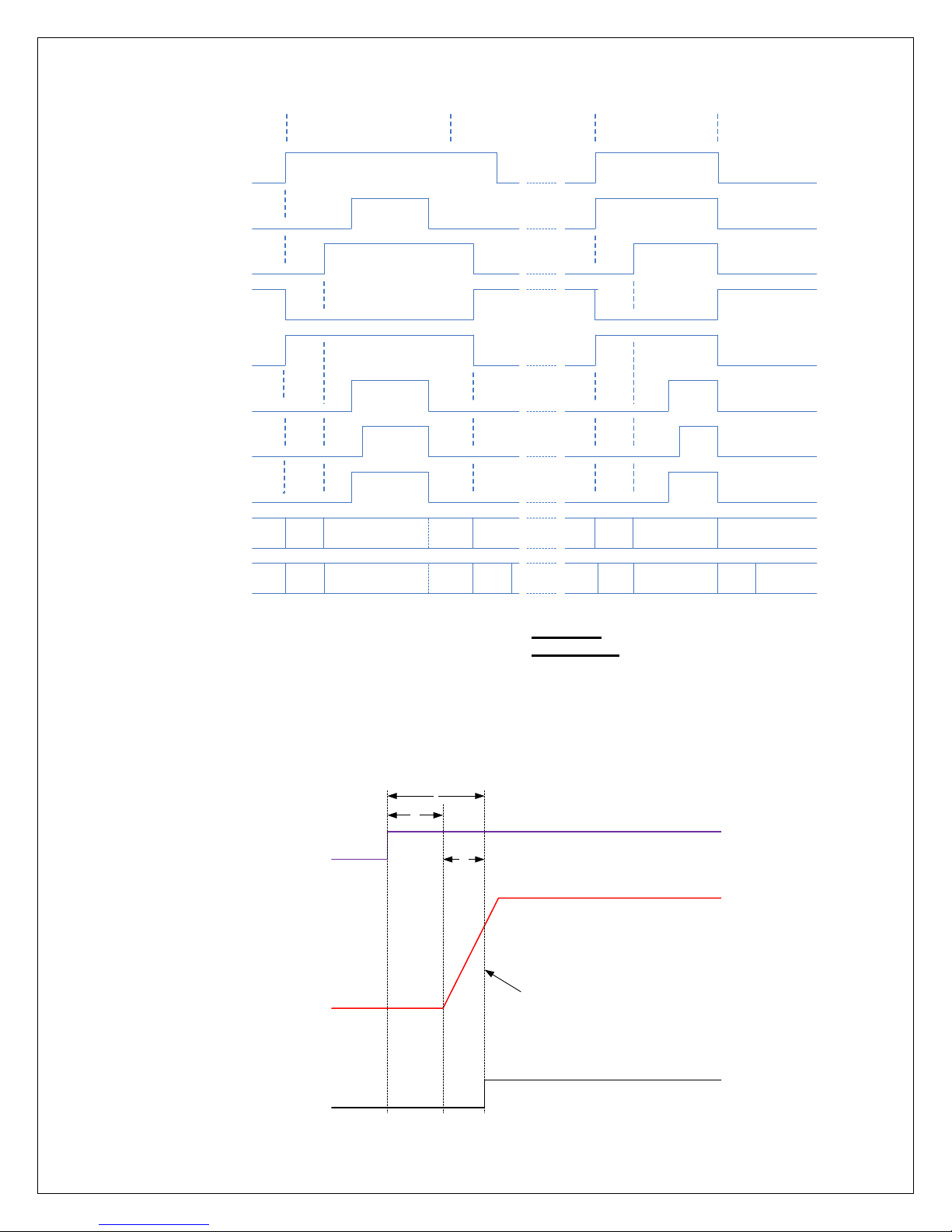
Exposure
kV
T1
T2
kV设定值的
75%
T
Xray_ON
Prep
Exposure
Ready
Filament Inhibit
Enable MA Program
Enable KV Program
DSP Inhibit
Xray On
Ma Servo
HSS Low
Speed States
HSS High
Speed States
STOP
STOP
BOOST
BOOST RUN
STOPRUN
RUN
Hang
Time
RUN
Hang
Time
BRAKE STOP
BOOST
BOOST RUN
STOPRUN
BRAKE STOP
Prep then Exposure
Prep & Exposure
Together
75% kV setting value
There are still other signals reflecting tim ing
relations with exposur e sequence, which are
provided for synchronizing purpose for user
system application.
See below the timing:
X-Ray On
75% Status:
Open collector output signal. High level is
active; indicate that the kV reach to 75%
setting value, and the exposure time begin to
accumulate.
PMX MANUAL 27 118164-001 REV. A
Page 33

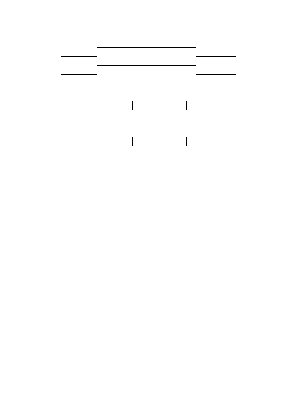
X-ray On
KV
Exposure
X-Ray On Status:
Open collector output signal. High level is
active; indicate that the HV output is
beginning.
See below the timing:
4.4.2 AEC Exposu re
In AEC Mode the external AEC control inp ut,
also called “X-Ray SHUTDOWN/AEC”, is
allowed to gate the high voltage on and off. In
order to generate X-Rays Prep, Exposure
Control and AEC must all be in the “ON”
state, which is High (Log ic 1). In ad ditio n the
unit must be in the ready state. When running
in AEC mode the exposure control timer only
runs when the AEC signal is high. The
exposure sequence term inates when any of
the following are true:
1. Prep goes inactive (low)
2. Exposure control goes in ac tive (lo w)
3. The exposure timer times out. (Timer is set
as part of exposure command)
4. The 30 second Prep time is exceeded.
When in AEC Mode it is assumed that the
AEC signal will be in the off state when the
exposure sequence terminates. If the AEC
signal is ON, an under -time fault will occur.
The rotor continues to run when the X-Ray is
shut off by the AEC signal. An example of
AEC timing is show below for the case of
Prep & Exposure together + HSS slow speed.
Also note, in AEC mode Break after
Exposure is automatic ally disabled, and will
not occur even if it is set. In addition the Break
after exposure hang time will be 30 seconds,
regardless of the current setting.
PMX MANUAL 28 118164-001 REV. A
Page 34
Prep
Exposure
Ready
AEC
(X-Ray Disable)
X-
Ray Enabled
X-Ray Disabled
HSS
STOP
BOOST
RUN
STOP
X
-Ray On
See below the Timing.
4.4.3 Smart AEC Expo sure
The main character of this mode is that preexposure is followed by the main exposure at
different parameter settings defined by the
system.
This mode has the ability to change
parameters during a n “exposure sequence”.
Exposure sequence is d efined a number of
Exposures whereby the System gates the
generator ON and OFF by the AEC
Shutdown signal input. The end of each
individual exposure would be normally
terminated by seconds or mAs programming.
In Smart AEC Mode (S-MAC) the exposure is
split into two parts. Both parts of the exposure
are required to use the same filament and
HSS speed, but the k V / mA / ex posure tim e
are allowed to change bet ween the first part
of the exposure and the second part. The
Prep, Exposure Control, X -Ray On (status),
and AEC signals, along with the serial
command port are all involved with Smart
AEC mode. The sequence of events for doing
a Smart AEC exposure is as follows:
1. The host sends the required commands
to set up the exposure. These are HSS
Speed, Filament, kV, mA, and exposure
time for 3 point mode, or Filament, kV
and mAs for 2 point mode. (Note that in
Fig 16 - AEC Timing
smart AEC, 2 point mode HSS Speed is
automatically set to Fast).
2. The host sets Prep “On”. The unit will go
into the Boost / Preheat phase on the
filament. (See Note 1).
3. The host sets exposure control ON and
AEC control ON to enable X-Rays. AEC
may be set ON before or simultaneous
with exposure control ON.
4. The unit will turn High voltage ON. High
voltage will remain ON until the
programmed exposure time has
elapsed. The host should monitor the XRay On status.
5. After the X-Ray On status transitions
from ON to OFF the Host should set the
AEC control to the X-Ray disabled state
(Low). The host must also leave the
exposure control ON during this time.
6. The host must now send the settings for
nd
part of the exposure over the
the 2
serial interface. Any combination of kV,
mA, exposure time if in 3-point mode, or
kV and mAs if in 2-point mode may be
changed. HSS Speed and Filament may
not be changed.
PMX MANUAL 29 118164-001 REV. A
Page 35

7. The host must wait a minimum of 20
milliseconds after the end of the last
command for the PMX unit to process
the commands. By the end of the 20
nd
millisecond period the 2
part of the
exposure will be set up and a new value
of preheat current applied to the
filament. (See Note 2).
8. The host sets the AEC signal High to
nd
indicate the 2
part of the exposure can
begin.
9. The PMX unit will turn High voltage ON.
High voltage will remain ON until the
programmed exposure time has
elapsed. The host should monitor the XRay On status.
10. When the X-Ray transitions to OFF the
exposure sequence is complete. The
Host can set Prep and Exposure Control
including the 2 second time to ready, can’t be
longer than 30 seconds.
Note 5: The AEC control signal M UST be in
the X-Ray disabled state (low) during the
nd
exposure settings upd ate for the 2
par t of
the exposure. The state of the AEC control
signal does not matter when setting up the 1
st
part of the exposure because Exposure
Control and Prep are low.
Note 6: In Smart AEC Mode, Commands,
request last exposure kV monitor and request
last exposure mA m onitor treat the first and
second part of the exposure as separate
exposures. For exam ple if the kV monitor is
requested after the f irst part of the exposure
has finished, but bef ore the sec ond part has
started, the average kV of the first part is
reported. If the k V m onitor is then requeste d
after the second part of the exposure has
finished, the averag e will be for the second
part of the exposure only.
to OFF.
Note 1: The time to read y is 2 seconds. The
exposure control signa l can be set ON prior
to the end of the 2 sec on d t ime, but the High
Voltage will not actuall y turn ON until the 2
seconds have elapsed from Prep active.
Note 2: Even though the new exposure
settings will be programmed and the new
nd
preheat set for the 2
par t of the exposure
within 20 milliseconds of receiving the last
setup command, the filament temperature
will not change ins tantaneously. Turning on
the high voltage immediately after the 20
millisecond period ends will not allow enough
time for the filament to reach the desired
temperature. This may result in large mA
nd
variations at the start of the 2
part of the
exposure.
Note 3: In Smart AEC mode, Break after
exposure is forced to “OFF”, and the Break
after exposure hang tim e set to 30 s econds,
regardless of the previously programmed
values. (This is the same as in standard AEC
mode).
Note 4: There is no specified m axim um tim e
between the first part a nd s econd part of th e
exposure. The limiting f actor is that the unit
can have Prep activ e for a maximum of 30
seconds, so the entire exposure sequence,
PMX MANUAL 30 118164-001 REV. A
Page 36

Prep
Ready
Exposure
Control
`
X-Ray On terminated by
exposure timer
X-Ray ON (Status)
X-Ray On terminated by
exposure timer
AEC
(X-Ray Disabled
when low)
Host sends new exposure
settings over Serial Link
20 millisecond
Delay after receiving new exposure
settings for VMX command processing
Exposure part 1 settings used Exposure part 2 settings used
Standby Boost / Preheat 1 MA-Servo 1 Preheat 1
Preheat 2
MA-Servo 2 Preheat 2
Standby
Filament
Host sets AEC Low prior to sending new
exposure settings
Host sets AEC High to
start 2
nd
part of
exposure
2 seconds
Fig 18 – Smart AEC Mode
Previous
Exposure
Value
Previous discarded
kV & mA report
Current values
Exposure Part 1
kV & mA
Being averaged
Exposure Part 1 average
kV and mA held
Exposure Part 2
kV & mA
Being Averaged
Exposure Part 2 average
kV and mA held
Value Returned using Request Last Exposure kV / mA Monitor
See below the timing sequence:
Notes:
Setting the AEC signal low before X-Ray On
status goes low (X-Ray Off) will cause an undertime fault.
Exposure commands sent at an illegal time
such as when AEC is high or X-Ray i s ON will
be ignored and will return a “State Error” code.
Exposure commands used to set up the 2nd
part of the exposure m ust be sent at the time
indicated in the diagram.
Aborting the Sm art AEC sequence by bring ing
Prep and/or Exposure control low in after the
part 1 exposure is finished but before the part 2
exposure is started will not generate a fault.
It is not allowed to change from 2-Point Mode to
It is required to se nd a new s etup between t he
part 1 exposure and part 2 exposure, even if the
new setup is exactly the s ame as the old. This
can be done using the “ Set Exposur e Settings”
command, or Individ ua l set c ommands such as
“Set Exposure kV”, “Set Exposure mA” and “Set
Exposure Time” if in 3 point mode, or “Set
Exposure kV”, and “Set Exposure mAs” in 2
point mode. It is allowed but not required to
send a Set Filament or Set HSS Speed
command, provided t he setting is the sam e as
in the part 1 exposure.
3-Point mode or the revers e in the middle of a
Smart AEC exposure.
PMX MANUAL 31 118164-001 REV. A
Page 37
LED
DEFINITION
COLOR
NORMAL
STATE
FUNCTION
DS1
Not used
DS2
+24V
GREEN
Lit
Indicate +24V power supply is acti ve.
DS3
DSP Alive
RED
Lit DS4
STATUS BIT1
YEL
Lit
3 bit status lines for status
messages matrix.
DS5
STATUS BIT2
YEL
Lit
DS6
STATUS BIT3
YEL
Lit
DS7
READY
YEL
Lit
Indicate the generator is ready for XRay exposure.
DS8
SPARE
YEL
Lit
DS9
FAULT
RED
Lit
Indicate generator fault.
DS10
X-Ray
shutdown/AEC
YEL
Lit
Indicate the status of the s ignal ( JB1-
12).
DS11
SF
YEL
Lit
Filament selection indicator.
DS12
Rotor on
GREEN
Lit
Starter status indicator.
DS13
HSS fault
RED
Lit
Indicate high speed starter fault.
DS14
Prep
GREEN
Lit
Synchronizing indication of Prep
signal.
DS15
Safety Int’lk
GREEN
Lit
Safety interlocks status indication.
DS16
X ray ON
RED
Lit
Synchronizing indication of X-Ray On
signal.
DS17
FPGA HEART
BEAT
YEL
Lit
Indicate FPGA is working.
DS18
Rotor brake
YEL
Lit
Indicate brake status of starter.
CHAPTER 5
TROUBLE SHOOTING
5.1 INTRODUCTION
Fault or error message will be indicated via
system status indicator or serial message
during abnormal operation. This Chapter
contains tables of those messages and
suggests actions to be taken by service
personnel to correct an y malfunctio ns that m ay
occur.
System Control Board 460220-001
5.2 STATUS AND ERROR CODES
5.2.1 Status Messages
LEDs provide status indication of the necessary
diagnostics needed for recognizing the
operation/shutdown mode of the generator.
LEDs display the following information:
messages.
Refer to chapter 3 the status
PMX MANUAL 32 118164-001 REV. A
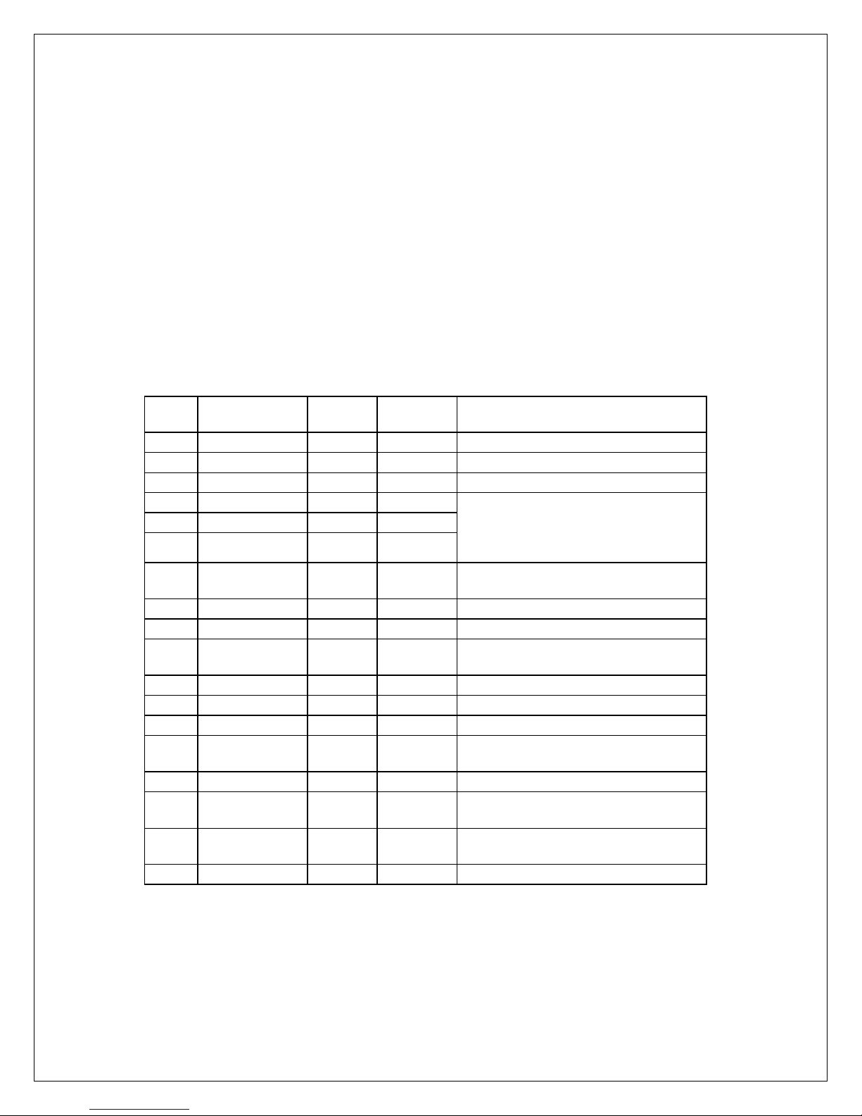
Page 38

NAME
Arg. #
DESCRIPTION
ACTION
Interlock 1
1
General Purpose Interlock Input 1
(Originally called Tube
the input pin results in a fault
condition. This was originally
for other purposes.
Check the short connection.
Interlock 2
2
General Purpose Interlock Input 2
(Originally called Tube Flow). An
open/logic high on the input pin
faulted condition. This was
for other purposes.
Check the short connection
HSS Fault
3
High Speed Starter Fault – Any Fault
1. Check the AC line voltage.
times boost within 1 minute.
ARC
4
ARC Fault – T he un it sh utdo wn high
voltage because an electric arc
occurred.
1. Check HV cable connections.
3. Replace the X-ray tube.
Over Power
5
An attempt was m ade to tu rn on the
a power output of greater than 5kW.
Over Time
6
This fault is possible only in AEC
because of the expiration of the
timer with AEC active)
Ensure that the cumulative time in
one exposure sequence not
Over mAs
7
The mAs of the current exposure has
value * then set exposure time.
Over Duty
8
The unit requires 20 seconds inbeing defined as entering prep,
Ensure that the exposure
operation within the duty cycle
limitation.
5.2.2 Faults Messages
Temperature). An open/logic high on
condition. A Logic low / Short to GND
is the “Good” or non-faulted
intended for connection to a tube
temperature switch, bu t can be used
results in a fault condition. A Logic
low / Short to GND is the “ Good” or
nonoriginally intended f or connection to
a tube flow switch, but can be used
related to operation of the high speed
starter.
generator with sett ings that result in
Mode. It indicates the unit shut-down
exposure timer, rather than the AEC
control signal. (Tim eout of exposure
exceeded the set value by 25%. This
is calculated by taking the average
current and multipl ying by exposure
time. The unit will fault immediately
when this happens, and shut down
the high voltage. Note that when in 2
point mode the limit is set to 125% of
the value programmed using the “Set
mAs” command. In 3 point mode it is
calculated by multi plying the set mA
2. Check the low voltage cable
connections.
3. Ensure that no more than 2
2. Season X-ray tube.
exceed the exposure timer (ms).
In AEC mode, expos ur e ti mer acts
as back up timer.
PMX MANUAL 33 118164-001 REV. A
between exposure cycles. A cycle
Page 39

exposure control on, high voltage on,
if the cumulative
AOP mode.
Over
9
This fault occurs if the output voltage
more).
Consult product support.
Over Current
10
If the output current exceeds 213.8
this fault will occur.
Consult product support.
Regulation
11
This fault occurs if the actual kV is
25% of the set
mA regulation.
1. Chec k the line volta ge in g ood
Open
12
Tube filament shows open (zero
applied to
1. Check the LV cable
3. Consult product support.
Filament
13
The filament current has exceeded
ubes, but as additional
tubes are added, this value may
change for the new tubes.
1. Check the preheat value.
hange setting value and
Ac/Dc
14
The rectified input v olt age t o th e uni t
more.
Check input line voltage
high voltage off, exit prep. The unit is
also limited to 5 seconds of exposure
time in any 2 minute period. If an
attempt is made before to turn on
high voltage in less the 20 seconds
after the last expos ure this fault will
occur. Also,
exposure time over the last 2 minutes
exceeds 5 seconds and an attempt is
made to turn high voltage on this fault
will occur.
Note: The 20 second lim it does not
apply to high voltage o n / off cycles
that are part of a sequence in AEC or
Voltage
Filament
(overcurrent)
exceeded 60kV for 1 mill isecond (or
mA for 100 milliseconds (or more)
exceeded by +/-10% or mA output
has exceeded +/value.
Note: There is a delay from high
voltage on to when the k V and mA
are checked to allow tim e for the kV
and mA to stabilize so false faults are
not generated. This time is 30 msec .
for kV regulation and 250 msec. for
current despite voltage
filament) for more than 2 seconds.
the set maximum limit of for more
than 200 msec.
The set lim it is 5.2A for all currentl y
supported t
condition.
2. Replace the X–ray tube
3. Consult product support.
connection
2. Measure filament resistance to
verify filament condition.
2. C
verify again.
3. Change to another X-ray tube.
4. Consult product support.
PMX MANUAL 34 118164-001 REV. A
is less than 255V DC for 1 second or
Page 40

Under Time
15
In manual or sm art AEC m ode, the
e to the
removal of the Prep or exposure
of the exposure Timer. (Exposure
was shorter then programmed).
Verify the control timing in
accordance with the function
Safety
Fault
16
An attempt was made to start an
exposure with the safety interlock
open. High voltage will not go on.
Check the safety interlock
Setup Fault
17
An attempt was made to start an
unit. High voltage will not go on.
Verify the setting value.
low and are not likely to cause any
is suitable for use in all
exposure terminated du
protocol.
control signals prior to th e expiration
Cannot occur in AEC mode.
Interlock
exposure (turn high voltag e on) with
connection.
an illegal setup progr am med into the
Notes:
If high voltage is on when a particular fault
occurs the high voltage will immediately be shut
off.
Over Time and Under Time faults can only
occur at the end of an ex posure (immediately
after high voltage is turned off). These faults
indicate an error in how the control signals were
the mode the unit was set up in, rather than a
fault in the PMX supp l y ope ration .
Over Duty faults can only occur at the transition
of exposure control fr om off to on. That is, r ight
at the start of an expos ure. Once an exposure
is started it will be al lowed to continue even if
after it is finished the on time exceeds 5
seconds over the previous 2 minutes.
applied as com pared to what was expected for
Table 1 – Guidance and MANUFACTURER’S declaration – ELECTROMAGNETIC EMISSIONS – for all ME
EQUIPMENT and ME SYSTEMS
Guidance and manufacturer’s declaration – electromagnetic emissions
The PMX is intended for use in the electromagnetic environment specified below. The customer or the
user of the PMX should assure that it is used in such an environment.
Emissions test Compliance Electromagnetic environment – guidance
RF emissions
CISPR 11
RF emissions
CISPR 11
Harmonic
emissions
IEC 61000-3-2
Voltage
fluctuations/
flicker emissions
IEC 61000-3-3
PMX MANUAL 35 118164-001 REV. A
Group 1 The PMX uses RF energ y onl y for its interna l
function. Therefore, its RF emissions are very
interference in nearby electr onic equi pment.
Class A The PMX
establishments other than domestic and those
directly connected to the public low-voltage
Not applicable
power supply networ k that supplies bui ldings
used for domestic purposes.
Not applicable
Page 41

The PMX is intended f or use in the electromagnet ic environment spec ified below. The c ustomer or the
user of the PMX should assure that it is used in such an environment.
Electrostatic
± 6 kV contact
± 6 kV contact
Floors should be wood, concrete or
Electrical fast
± 2 kV for power
1 kV for
± 2 kV for power
1 kV for
Mains power qualit y should be that of a
typical commercial or hospital
Surge
± 1 kV line(s) to
2 kV line(s) to
± 1 kV line(s) to
Mains power qualit y should be that of a
typical commercial or hospital
Voltage dips,
<5 % UT
<5 % UT
Mains power qualit y should be that of a
typical commercial or hospital
requires continued operation during
power mains interruptions, it is
Power
Power frequency magnet ic fields should
location in a typical commercial or
Table 2 – Guidance and MANUFACTURER’S declaration – ELECTROMAGNETIC EMISSIONS – for all ME
EQUIPMENT and ME SYSTEMS
Guidance and manufacturer’s declaration – electromagnetic immunity
Immunity test IEC 60601 test
level
discharge
(ESD)
± 8 kV air
IEC 61000-4-2
transient/burst
IEC 61000-4-4
supply lines
±
input/output
lines
IEC 61000-4-5
line(s)
±
earth
short
interruptions
and
voltage
variations
on power supply
input lines
IEC 61000-4-11
(>95 % dip in UT)
for 0,5 cycle
40 % UT
(60 % dip in UT)
for 5 cycles
70 % UT
(30 % dip in UT)
for 25 cycles
<5 % UT
(>95 % dip in UT)
for 5 s
Compliance level Electromagnetic environment –
guidance
± 8 kV air
ceramic tile. If floors are covered with
synthetic material, the relative humidity
should be at least 30 %.
supply lines
±
environment.
input/output
lines
line(s)
± 2 kV line(s) to earth
environment.
(>95 % dip in UT)
for 0,5 cycle
environment. If the user of the PMX
40 % UT
(60 % dip in UT)
for 5 cycles
70 % UT
(30 % dip in UT)
recommended that the PMX be powered
from an uninterruptible power supply or a
battery.
for 25 cycles
<5 % UT
(>95 % dip in UT)
for 5 s
frequency
be at levels characteristic of a typical
(50/60 Hz)
3 A/m 3 A/m
magnetic field
hospital environment.
IEC 61000-4-8
NOTE UT is the A.C. mains voltage prior to application of the test level.
PMX MANUAL 36 118164-001 REV. A
Page 42

The PMX is intended for use in the electromagnetic environment specified below. The customer or the user of the PMX
should assure that it is used in such an environment.
Portable and mobile RF communications equipment
distance calculated from the equation applicable to
Recommended separation dist anc e
d = 1.17 √P 80 MHz to 800 MHz
d = 2.33 √P 800 MHz to 2.5 GHz
transmitter in watts (W) according to the transmitter
NOTE 1 At 80 MHz and 800 MHz, the higher frequency range applies.
NOTE 2 These guidelines may not apply in all situations. Electromagnetic propagation is affected by absorption and
reflection from structures, objects and people.
a. Field strengths from fixe d transmitters, such as base stations for radio (cellular/cordless) telephones and land mobile
radios, amateur radio, AM and FM radio broadcast and TV broadcast cannot be predicted theoretically with accuracy. To
lectromagnetic env ironment due to fixed RF tran smitt ers, an ele ctromag netic si te survey should be con sidere d.
ed to verify normal operation. If abnormal performance is observed, additional measures may be
Table 4 – Guidance and MANUFACTURER’S declaration – electromagnetic IMMUNITY – for ME EQUIPMENT
and ME SYSTEMS that are not LIFE-SUPPORING
Guidance and manufacturer’s decl arat ion – electromagnetic immunity
Immunity test IEC 60601 test level Compliance level Electromagnetic environment – guidance
Conducted RF
IEC 61000-4-6
Radiated RF
IEC 61000-4-3
3 Vrms
150 kHz to 80 MHz
3 V/m
80 MHz to 2.5 GHz
3 Vrms
3 V/m
should be used no closer to any part of the PMX,
including cables, than the recommended separation
the frequency of the transmitter.
d = 1.17 √P
Where P is the maximum output power rating of the
manufacturer and d is the recommended separation
distance in meters (m).
Field strengths from fixed RF transmitters, as
determined by an electromagnetic site survey,
should be less than the compliance level in each
frequency range.
Interference may occur in the vicinity of equipment
marked with the following symbol:
b
a
assess the e
If the measured field strength in the location in whic h the PMX is used exceeds the applicable RF compliance level above,
the PMX should be observ
necessary, such as re-orienting or relocating the PMX.
b. Over the frequency range 150 kHz to 80 MHz, field strengths should be less than 3 V/m.
PMX MANUAL 37 118164-001 REV. A
Page 43
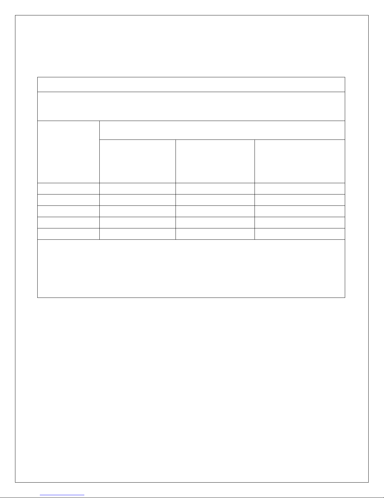
Recommended separation distances between portable and mobile RF communications equipment
and the PMX
The PMX is intended for use in an electromagnetic environment in which radiated RF disturbances are
as recommended below, according to the maximum output power of the communications equipment.
Separation distance according to frequ ency of transmitter
For transmitters r ated at a maximum output power n ot list e d ab ove, t he rec om mended separation dis tanc e d
absorption and reflection from structures, objects and people.
Table 6 – Recommended separation distances between portable and mobile RF communications equipment
and the ME EQUIPMENT or ME SYSTEM – for ME EQUIPMENT and ME SYSTEMS that are not LIFE-
SUPPORTING
controlled. The customer or the user of the PMX can help prevent electromagnetic interference by maintaining
a minimum distance between portable and mobile RF communications equipment (transmitters) and the PMX
m
Rated maximum
output
power of
transmitter
150 kHz to 80 MHz
d = 1.17 √P
80 MHz to 800 MHz
d = 1.17 √P
800 MHz to 2,5 GHz
d = 2.33 √P
W
0.01 0.117 0.117 0.233
0.1 0.370 0.370 0.737
1 1.17 1.17 2.33
10 3.70 3.70 7.37
100 11.7 11.7 23.3
in meters (m) can be determined using the equation applicable to the frequency of the transmitter, where P is
the maximum output power rating of the transmitter in watts (W) according to the transmitter manufacturer.
NOTE 1 At 80 MHz and 800 MHz, the separation distance for the higher frequency range applies.
NOTE 2 Thes e guidelines may not appl y in all situat ions. Electromagnetic propagat ion is affected b y
PMX MANUAL 38 118164-001 REV. A
Page 44

CHAPTER 6
MAINTENANCE
6.1 INTRODUCTION
If a major component (such as the
multiplier module or system control
board) is replaced, recalibration will be
needed. The acceptance test procedure
WARNING: ALWAYS SWITCH OFF MAINS POWER TO THE GENERATOR AND WAIT A
MINIMUM OF 5 MINUTES FOR CAPACITORS TO DISCHARGE BEFORE
BEGINNING ANY MAINTENANCE.
6.2 PERFORMANCE TEST
Only qualified personnel should perform
these tests.
High voltage test procedures are describe d
in Spellman Bulletin STP-783, Standard
Test Procedures for High Voltage Power
Supplies. Copies c an be obtained f rom the
Spellman Customer Service Department.
Test equipment, inclu ding an oscilloscope,
a high impedance voltmeter, and a high
voltage divider such as the Spellm an HVD100 or HVD-200, is needed for performance
tests. All test components must be rated for
operating voltage.
per Chapter 5 should then be performed
prior to placing the generator back into
service.
6.3 HIGH VOLTAGE DIVIDERS
High voltage dividers for precise
measurement of output voltage with
accuracy up to 0.1% are available from
Spellman. The HVD-100 is used for
voltages up to 100kV. The HVD-200
measures up to 200kV. The Spellman
divider is designed for use with differential
voltmeters or high impedance digital
voltmeters. The high input impedance is
ideal for measuring high voltage low current
sources, which would be overloaded by
traditional lower impedance dividers.
PMX MANUAL 39 118164-001 REV. A
Page 45

C
CHAPTER 7
REPLACEMENT
PARTS
7.1 Replacement Parts
ontact the Spellman Customer Service
Department for parts lists for specific models.
Spellman provides p arts and subassem blies for its
high voltage power s upplies but recommends that
only qualified personnel perform repairs. High
voltage is dangerous; even minor mistakes in
repairs can have serious consequences.
When requesting parts, please provide the complete
model number and serial number of the power
supply in question.
7.2 Correspondence and
Ordering Spare Parts
Each Spellman power s upply has an identification
label on the rear of the chassis that bears its model
and serial number.
When requesting engineering or applications
information, please state the model and serial
number of the power supply. If specific components
or circuit sections are involved in the inquiry, it is
helpful to indicate the component symbol number(s)
shown on the applicable schematic diagram.
When ordering spare parts, please specify the
part’s description, the part’s reference designation
or part number, and the model and serial number
of the unit.
PMX MANUAL 40 118141-002 REV
Page 46

CHAPTER 8
FACTORY SERVICE
8.1 Warranty Repairs
During the Warrant y period, Spellm an will repair al l
units free of charge. The Warranty is void if the unit
is worked on by other than Spellman personnel.
See the Warranty in the rear of this manual for more
information. Follow the return procedures described
in Section 8.2. The customer shall pay for shipping
to and from Spellman.
8.2 Factory Service Procedures
Spellman has a well-equipped factory repair
department. If a unit is returned to the factory for
calibration or repair, a detailed description of the
specific problem should be attached.
For all units returned for repair, please obtain an
authorization to ship from the Customer Service
Department, either by phone or mail prior to
shipping. When you call, please state the model
and serial numbers, which are on the plate on the
rear of the power supply, and the purchase or der
number for the repair. A Return Material
Authorization Code Number (RMA Number) is
needed for all returns. This RMA Number should be
marked clearly on the outside of the shipping
container. Packages received without an RMA
Number will be returned to the customer. The
Customer shall pay for shipping to and from
Spellman.
A preliminary estim ate for repairs will be given by
phone by Customer Servic e. A purchase order f or
this amount is requested upon issuance of the RMA
Number. A more detailed estimate will be made
when the power su ppl y is rec eived at the Spe llman
Repair Center. In the event that repair work is
extensive, Spellman will call to seek additional
authorization from your company before completing
the repairs.
8.3 Shipping Instructions
All power supplies returned to Spellman must be
sent shipping prepaid. Pac k t he units caref ull y and
securely in a suitable container, preferably in the
original container, if available. The power supply
should be surrounded by at least four inches of
shock absorbing material. Please return all
associated materials, i.e. high voltage output
cables, interconnect ion cab les, etc ., so t hat we c an
examine and test the entire system.
All correspondence and phone calls should be
directed to:
Spellman High Voltage Electronics Cor p .
475 Wireless Boulevard
Hauppauge, New York 11788
TEL: (631) 630-3000 FAX: (631) 435-1620
E-Mail: sales@Spellmanhv.com
www.spellmanhv.com
PMX MANUAL 41 118164-001 REV. A
Page 47

To obtain information on Spellman’s product warranty please visit our website at:
http://www.spellmanhv.com/en/About/Warranty.aspx
Page 48

1
PMX Power Supply Protocol Definitions
50kV
Copyright 2017, Spellman High Voltage Electronics Corporation. All Rights
Reserved.
This information contained in this publication is derived in part from proprietary and patent data. This
information has been prepared for the express purpose of assisting operating and maintenance personnel in
the efficient use of the model described herein, and publication of this information does not convey any right
to reproduce it or to use it for any purpose other than in connection with installation, operation, and
maintenance of the equipment described.
118165-001 REV. A
475 Wireless Boulevard • Hauppauge, New York 11788, USA • www.spellmanhv.com • T:+1 631.630.3000 • F:+1 631.435.1620
Page 49

2
Table of Contents
1.0 Serial Communications Interface ......................................................... 5
2.0 Etherenet Communications Interface .................................................. 6
2.1. TCP/IP FORMAT ..................................................................................... 6
2.2. Ethernet Command Format ..................................................................... 7
2.3. Ethernet / RS232 use .............................................................................. 7
3.0 Serial Commands – RS232 SERIAL Protocol ............................................. 8
3.1 Serial Interface Message Format ............................................................. 8
3.2 Command Arguments .............................................................................. 8
3.3 Checksums .............................................................................................. 8
3.4 Checksum Errors: .................................................................................... 9
3.5 Timeouts: ................................................................................................. 9
4.0 Command Overview ................................................................................ 10
4.1 Command Mode Commands ................................................................ 10
4.2 Service Mode Commands ................................................................... 12
4.3 Response Overview ............................................................................ 13
4.3.1 Set Command Response Format ........................................................ 13
4.3.2 Request Command Response Format. ............................................... 13
4.3.3 Warnings and Er r ors ............................................................................ 14
4.4 Detailed Command Structure .............................................................. 15
4.4.1 Request Analog Monitor Readbacks ................................................... 15
4.4.2 Request Status ................................................................................... 18
4.4.3 Request Fa ul t Stat us .......................................................................... 22
4.4.4 Reset Faults ........................................................................................ 25
4.4.5 Set Exposur e Set ti ng s ........................................................................ 26
4.4.6 Get Expos ure S etti ng s ........................................................................ 28
4.4.7 Set HSS Speed ................................................................................... 29
4.4.8 Set Exposur e Tim e ............................................................................. 32
4.4.9 Set Exposur e k V ................................................................................. 34
4.4.10 Set Exposur e mA ............................................................................... 35
4.4.11 Set Exposure Filament (large spot / small spot) ................................. 37
4.4.12 Set Exposur e mAs .............................................................................. 39
118165-001 REV. A
475 Wireless Boulevard • Hauppauge, New York 11788, USA • www.spellmanhv.com • T:+1 631.630.3000 • F:+1 631.435.1620
Page 50

3
4.4.13 Request Exposure Time Set-point ...................................................... 40
4.4.14 Request kV S et-Point ......................................................................... 41
4.4.15 Request Exposure mA Set-Point ........................................................ 42
4.4.16 Request Exposure Filament Setting ................................................... 43
4.4.17 Request Exposure mAs setting .......................................................... 44
4.4.18 Request Last Exposure kV Monitor .................................................... 45
4.4.19 Request Last Exposure mA Monitor ................................................... 46
4.4.20 Get Last Exposure Time .................................................................... 47
4.4.21 Set Brake After Exposure ................................................................... 48
4.4.22 Set Break After Exposure Hang Time ................................................ 49
4.4.23 Get Break After Exposure Hang Time ................................................ 50
4.4.24 Set AEC Mode (Standard Automatic Exposure Control Mode) .......... 51
4.4.25 Request AEC Mode ........................................................................... 52
4.4.26 Set 2-Point / 3-Point Mode ................................................................. 53
4.4.27 Request 2-Point / 3-Point Mode ......................................................... 54
4.4.28 Set Smart AEC Mode ......................................................................... 55
4.4.29 Request Smart AEC Mode ................................................................. 56
4.4.30 Request Current X-Ray Tube Anode Heat Loading ........................... 57
4.4.31 Request Auxiliary Status .................................................................... 58
4.4.32 Request Expanded Fault Status ......................................................... 59
4.4.33 Request Expanded HSS Status ......................................................... 60
4.5 Service Mode Structure ......................................................................... 62
4.5.1 Program Filament Li mit ...................................................................... 62
4.5.2 Request Filament Limi t Set Point ....................................................... 63
4.5.3 Request Filament Pre-Heat Set Poi nt ................................................ 64
4.5.4 Set Exposur e Sett ings Max Exposure Time ....................................... 65
4.5.5 Request Max Exposure Time ............................................................. 66
4.5.6 Set Exposure Settings Pre-Heat Value ............................................... 67
4.5.7 Set Ready For Exposure Time ........................................................... 68
4.5.8 Get Ready For Exposure Time ........................................................... 69
4.5.9 Set Maxi mu m mA s ............................................................................. 70
4.5.10 Get Maximum mAs ............................................................................. 71
4.5.11 Request Filament Current Feedback .................................................. 72
4.5.12 Get Revison ........................................................................................ 73
118165-001 REV. A
475 Wireless Boulevard • Hauppauge, New York 11788, USA • www.spellmanhv.com • T:+1 631.630.3000 • F:+1 631.435.1620
Page 51

4
4.5.13 Set Baud Rate .................................................................................... 74
4.5.14 Set Calibration Mode On / Off ............................................................ 75
4.5.15 Get Calibration Status ........................................................................ 76
4.6 Serial Command Handling ..................................................................... 78
5.0 Predictive filament .................................................................................. 79
6.0 General Timing ........................................................................................ 81
7.0 Brake After Exposure ............................................................................. 82
8.0 AEC (Automatic Exposure Control) Mode ............................................ 84
9.0 2-Point and 3-Point Mode ....................................................................... 85
10.0 Smart AEC Mode ..................................................................................... 87
11.0 Calibration Mode ..................................................................................... 91
118165-001 REV. A
475 Wireless Boulevard • Hauppauge, New York 11788, USA • www.spellmanhv.com • T:+1 631.630.3000 • F:+1 631.435.1620
Page 52

5
1. Serial Communications Interface
Serial communications will use the following protocol:
<STX><CMD><,>ARG><,><CSUM><ETX>
Where:
<STX> = 1 ASCII 0x02 Start of Text character
<CMD> = 2 ASCII characters representing the command ID
<,> = 1 ASCII 0x2C character
<ARG> = Command Argument
<,> = 1 ASCII 0x2C character
<CSUM> = Checksum (see section 1.2 for details)
<ETX> = 1 ASCII 0x03 End of Text character
The serial interface has the following attributes:
• 19.2K baud (Default baud rate, can be changed to 115K baud for
reprogramming of the firmware)
• No Parity
• 8 Data Bits
• 1 Stop Bit
• No Hand shaking
1.1 Command Arguments
The format of the numbers for comma nd ar g ume nt s is a v ari able length
string. To represent the number 42, the string ‘42’, ‘042’, or ‘0042’ can be
used. This being the case, commands and responses that carry data are
variable in length.
1.2 Check Sums
The checksum is computed as follows:
• Add the <CMD>, <,>, and <ARG> bytes into a 16 bit (or larger) word.
The bytes are added as unsigned integers.
• Take the 2’s compliment (negate it).
• Truncate the result down to the eight least significant bits.
• Clear the most significant bit (bit 7) of the resultant byte, (bitwise AND with
0x7F).
• Set the next most significant bit (bit 6) of the resultant byte (bitwise OR
with 0x40).
Using this method, the checksum is always a number between 0x40 and
0x7F.
The checksum can never be confused with the <STX> or <ETX> control
characters, since these have non-overlapping ASCII values. If the DSP
detects a checksum error, the received message is ignored and the supply
will respond with and error code of 1 (see section 3.4).
118165-001 REV. A
475 Wireless Boulevard • Hauppauge, New York 11788, USA • www.spellmanhv.com • T:+1 631.630.3000 • F:+1 631.435.1620
Page 53

6
2. Ethernet Communications Interface
Byte
0
Protocol
Header
Length
Type Of
Total Length
4
Packet ID
Flags
Fragmentation Offset
8
Time To Live
Protocol
Header checksum
12
Source Address
16
Destination Address
20
Source Port
Destination Port
24
Sequence Number
28
Acknowledgement Number
32
Data
Offset
Reserved
Code Bits Window
36
Checksum
Urgent Pointer
40
Data Byte 1
Data Byte 2
Data Byte 3
Data Byte N
2.1. TCP/IP FORMAT
Each Ethernet command will consist of a TCP/IP header followed by the
required data bytes as specified in secti on 2.2 . Figure 24 summarizes the
TCP/IP header configuration. Please note that this functionality is provided
by the software implementation of the Open Systems Interconnection
(OSI) TCP/IP protocol stack, specifically the upper 4 layers.
Version
Service
Figure 24: Network TCP/IP datagram header
118165-001 REV. A
475 Wireless Boulevard • Hauppauge, New York 11788, USA • www.spellmanhv.com • T:+1 631.630.3000 • F:+1 631.435.1620
Page 54

7
2.2. Ethernet Command Format
The Ethernet command format is:
<STX><CMD><,>ARG><,><CSUM><ETX>
Where:
<STX> = 1 ASCII 0x02 Start of Text character
<CMD> = 2 ASCII characters representing the command ID
<,> = 1 ASCII 0x2C character
<ARG> = Command Argument
<,> = 1 ASCII 0x2C character
<CSUM> = Checksum (see section 3.3 for detai l s)
<ETX> = 1 ASCII 0x03 End of Text character
This is exactly the same format as the RS232 serial commands as defined
in section 3. The Ethernet interface acts as a transport for the serial PMX
commands. The commands the ms elves have the exact same format , responses
and meanings as with the RS232 serial command. The command for mats,
responses, and examples as shown in section 4 apply equally to both RS232 and
Ethernet communication.
2.3. Ethernet / RS232 use
PMX will accept commands via the RS232 serial link or the Ethernet
interface, but only one communication interface can be used at a time. You
cannot send commands over RS232 and Ethernet both at the same time. Using
both RS232 and Ethernet concurrently is not allowed and trying to do so will
cause unreliable communication and erratic operation. Note also that firmw ar e
upgrade over the Ethernet interface is not supported. This function is available
only over the RS232 interface.
118165-001 REV. A
475 Wireless Boulevard • Hauppauge, New York 11788, USA • www.spellmanhv.com • T:+1 631.630.3000 • F:+1 631.435.1620
Page 55

8
3.0 Serial Commands – RS232 SERIAL Protocol
3.1 Serial Interface Message Format
Serial communications will use the following format:
<STX><CMD><,>ARG><,><CSUM><ETX>
Where:
<STX> = 1 ASCII 0x02 Start of Text character
<CMD> = 2 ASCII characters representing the command ID
<,> = 1 ASCII 0x2C character
<ARG> = Command Argument
<,> = 1 ASCII 0x2C character
<CSUM> = Checksum (see section 3.3 for detai l s)
<ETX> = 1 ASCII 0x03 End of Text character
3.2 Command Arguments
The format of the numbers used for command arguments is a variable
length string. To represent the number 42, the string ‘42’, ‘042’, or ‘0042’
can be used. This being the case, commands and responses that carry
data are variable in length.
3.3 Checksums
The checksum is computed as follows:
• Add the <CMD>, <,>, and <ARG> bytes into a 16 bit (or larger)
word. The bytes are added as unsigned integers.
• Take the 2’s compliment (negate it).
• Truncate the result down to the eight least significant bits.
• Clear the most significant bit (bit 7) of the resultant byte, (bitwise
AND with 0x7F).
• Set the next most significant bit (bit 6) of the resultant byte (bitwise
OR with 0x40).
Using this method, the checksum is al ways a number between 0x40 and
0x7F. The checksum can never be confused with the <STX> or <ETX>
control characters, since these have non-overlapping ASCII values.
The following is sample code, written in Visual Basic, for the generation of
checksums:
Public Function ProcessOutputString(outputString As String) As String
118165-001 REV. A
475 Wireless Boulevard • Hauppauge, New York 11788, USA • www.spellmanhv.com • T:+1 631.630.3000 • F:+1 631.435.1620
Page 56

9
Dim i As Integer
Dim CSb1 As Integer
Dim CSb2 As Integer
Dim CSb3 As Integer
Dim CSb$
Dim X
X = 0
For i = 1 To (Len(outputString)) 'Starting with the CMD character
X = X + Asc(Mid(outputString, i, 1)) 'adds ascii values together
Next i
CSb1 = 256 - X
CSb2 = 127 And (CSb1) 'Twos Complement
CSb3 = 64 Or (CSb2) 'OR 0x40
CSb$ = Chr(Val("&H" & (Hex(CSb3))))
ProcessOutputString = Chr(2) & outputString & CSb$ & Chr(3)
End Function
3.4 Checksum Errors:
If the DSP detects a checksum error, the received message is ignored ,
and the unit responds with a command byte equal to 1 as shown in the
following sequence:
<STX>1,<CSUM><ETX>.
The 1 in the command byte indicates a checksum error has occurred.
3.5 Timeouts:
There exists the possibility that the message from the Host to the unit is
distorted so badly that the unit can’t process the message at all and no
response will be sent. The host should implement a time out of 100
milliseconds from when the message is sent. If the host sends a message
and no response is received before this 100ms timeout expires the host
should use this an implied NAK and assume the command was not
received by the unit.
118165-001 REV. A
475 Wireless Boulevard • Hauppauge, New York 11788, USA • www.spellmanhv.com • T:+1 631.630.3000 • F:+1 631.435.1620
Page 57

10
Command Mode RS232 Commands
Command Name
<CMD>
<ARG>
RANGE
Request Analog Monitor
19
None
-
Request Status
22
None
-
Reset Faults
31
None
-
Set Exposure Settings
50
1-4 ASCII
See cmd
Get Exposure Settings
51
None
-
Set Exposure Time
72
1 ASCII
20-12000
Set Exposure kV
10
1 ASCII
0-4095
Set Exposure mA
11
1 ASCII
0-4095
Set Exposure Filament
73
1 ASCII
0-1
Set Exposure mAs
74
1 ASCII
1-6000
Request Exposure Tim e
Setpoint
52
None
-
Request Exposure kV
Setpoint
14
None
-
Request Exposure mA
Setpoint
15
None
-
Request Exposure
Filament Setting
53
None
-
Request Exposure mAs
Setpoint
54
None
-
Set HSS Speed
59
None
0 or 1
Request Fault Status
68
None
-
4.0 Command Overview
Commands are separated into two modes: command and service modes.
Command mode is for normal operation and service mode for modifying
certain parameters and reading their value. Service mode commands are
not meant to be used as part of normal oper at i on. Th ey are intended for
system testing and unit servicing.
4.1 Command Mode Commands
Readbacks
118165-001 REV. A
475 Wireless Boulevard • Hauppauge, New York 11788, USA • www.spellmanhv.com • T:+1 631.630.3000 • F:+1 631.435.1620
Page 58

11
Command Mode RS232 Commands
Request Last Exposure kV
monitor
60
None
-
Request Last Exposure
61
None
-
Get Last Exposure Length
65
None
-
Set Brake After Exposure
35
1 ASCII
0-1
Set Brake After Exposure
36
1 ASCII
0-65535
Get Brake After Exposure
37
None
-
Set AEC Mode
57
1 ASCII
0-1
Request AEC Mode
58
None
-
Set 2-Point / 3 –Point
55
1 ASCII
0-1
Request 2-Point / 3 –
56
None
-
Set Smart AEC Mode
75
1 ASCII
0-1
Request Smart AEC Mode
76
None
-
Request Current Anode
77
None
-
Request Auxiliary Status
78
None
-
Request Expanded Fault
69
None
-
Request Expanded HSS
84
None
-
mA monitor
Hang Time
Hang Time
Exposure Mode
Point Exposure Mode
Heat Load
Status
Status
118165-001 REV. A
475 Wireless Boulevard • Hauppauge, New York 11788, USA • www.spellmanhv.com • T:+1 631.630.3000 • F:+1 631.435.1620
Page 59

12
Service Mode RS232 Commands
Command Name
<CMD>
<ARG>
RANGE
Set Baud Rate
07
1 ASCII
2 = 19200, 5 =
Program Filament
12
1-ASCII
0-4095
Request Filament
Limit Setpoint
16
None
-
Request Filament
Pre-Heat Setpoint
17
None
-
Get Revision
27
None
-
Set Exposure
Exposure Time
40
1 ASCII
0-10000
Request Max
Exposure Time
32
None
-
Set Exposure
Value
33
1 ASCII
0-4095
Set Ready For
Exposure Time
34
1 ASCII
0-4095
Get Ready For
42
None
-
Set Maximum mA s
38
1-4 ASCII
0-600
Get Maximum mA s
39
None
-
Request Filament
Current Feedback
62
None
-
Set Calibration
Mode
28
1 ASCII
0-1
Request Calibration
Status
29
None
-
4.2 Service Mode Commands
115200
Limit
Settings Max
Settings PreHeat
Exposure Time
118165-001 REV. A
475 Wireless Boulevard • Hauppauge, New York 11788, USA • www.spellmanhv.com • T:+1 631.630.3000 • F:+1 631.435.1620
Page 60

13
4.3 Response Overview
The responses to the above commands will follow one of two
general formats depending on whether the command was a set
command, intended to modify system or exposure setup, or a
request command, intended to return system status, current setup
or exposure information.
4.3.1 Set Command Response Format
The general format the response to a set command is:
<STX><CMD>,<$-OR-ERR/WARN>,<CSUM><ETX>
Where:
<STX> = 1 ASCII 0x02 Start of Text character
<CMD> = 2 ASCII characters echoing the command ID
<,> = 1 ASCII comma (0x2C character)
<$-OR-ERR/WARN> = If the setting(s) specified by the command
are valid this will be the ASCII $ character.
If the setting is invalid or results in an invalid
setup for the system a 1 or 2 character code
will be returned. See the following section
on warnings and errors.
<,> = 1 ASCII comma 0x2C character
<CSUM> = Checksum (see section 3.3 for details)
<ETX> = 1 ASCII 0x03 End of Text character
4.3.2 Request Command Response Format.
The general format for the response to a request command is:
<STX> <CMD>,<ARG1>,{<A R Gn>,}<CSUM><EXT>
Where:
<STX> = 1 ASCII 0x02 Start of Text charac ter
<CMD> = 2 ASCII characters echoing the command ID
<,> = 1 ASCII comma (0x2C character)
<ARG> = A data value consisting of a variable number of ASCII
characters. The actual meaning is command dependent.
,<ARG+n>= Additional ASCII data values separated from the
previous value by a comma. Additional values may
not be present depending on the command and the
number of additional values is command dependent.
<,> = 1 ASCII comma 0x2C character
<CSUM> = Checksum (see section 3.3 for details)
<ETX> = 1 ASCII 0x03 End of Text character
118165-001 REV. A
475 Wireless Boulevard • Hauppauge, New York 11788, USA • www.spellmanhv.com • T:+1 631.630.3000 • F:+1 631.435.1620
Page 61

14
4.3.3 Warnings and Errors
As mentioned in section 4.3.1 set commands are responded to with either
a “$” (dollar sign) character or a 1 or 2 character long ASCII format
numeric code that can be an error or a warning.
- A response of a $ character indicates successful r ecep t ion and
processing of the sent value. The value sent in the command
has been accepted and is now the active value that will be used
by the system.
- A response of an ASCII encoded number 3 -9 indicates a
parameter error. This means one or more of the values sent in
the command is invalid, or out of range. The value(s) in the
command are ignored and the old values that the system is set
for remain in effect. Some of the “Set” commands only set a
single value. For these commands an err or code o f 3 indica tes
an invalid or out of range parameter. This is the only possible
error for these functions. Some functions, such as the “Set
Exposure” function use multiple error codes. For these
commands the meaning of the error codes is dependent on the
particular command. See the individual command for a list of
possible error codes and their meaning.
- A response of an ASCII “10” (2 characters) indicates a w ar ni ng .
This is a possible response for commands that modify exposure
settings. It indicates that the parameter in the command is in
range, but when combined with the other current supply settings
results in an invalid set up. The new value has been accepted
but the supply is now in an “invalid programming” condition.
The high voltage will not turn on if commanded. If the intent of
the user is to send additional commands to complete the
change of exposure settings this warning can be safely ignored.
If the user’s intent is to start an exposure without further
changes to the exposure settings however, It indicates a
problem. The user must resolve the setup problem before an
exposure can begin.
118165-001 REV. A
475 Wireless Boulevard • Hauppauge, New York 11788, USA • www.spellmanhv.com • T:+1 631.630.3000 • F:+1 631.435.1620
Page 62

15
4.4 Detailed Command Structure
4.4.1 Request Analog Monitor Readbacks
Description:
The host requests that the firmware transmit the present values of
Analog Monitor Readbacks. All read back values are in the range 0
– 4095. See the scaling summary table after the description of
values to convert from scaled value to actual value of voltage or
current. Please note that the voltage scaling for the monitor
voltages is not the same as their respective set values.
Direction:
Host to supply
Syntax:
<STX><19><,><CSUM><ETX>
Example:
<STX><19>,<CSUM><ETX>
Response:
<STX><19><,><ARG1><,><ARG2><,><ARG3<,><ARG4><,><AR
G5><,><ARG6><,><ARG7><,><ARG8><,><ARG9><,><ARG10><
,><ARG11><,><ARG12><,><ARG13><,><ARG14><,><ARG15><,
><ARG16><,> <CSUM><ETX>
Where: (ARG# in ASCII format)
ARG1 = +15V = 0 – 4095 (scaling = 0.0062256 V/Bit)
ARG2 = -15V = 0 – 4095 (0.0043663*ARG – 16.4665)
ARG3 = +24V = 0– 4095 (0.0104762 V/Bit)
ARG4 = +3.3Va = 0 – 4095 (0.00310847 V/Bit)
ARG5 = +3.3Vb = 0– 4095 (0.0011978 V/B it)
ARG6 = TBD
ARG7 = TBD
ARG8 = TBD
ARG9 = Filament Voltage Monit or = 0-4095 = 0–11.78V
ARG10 = KV Feedback Monitor = 0-4095 = 0-53,476V
ARG11 = MA Feedback Monitor = 0-4095 = 0-213.828mA
ARG12 = DC Voltage Monitor = 0-4095 = 0-346.4V
ARG13 = Leak Limit monitor = 0–4095 = 106.914
ARG14 = Filament Feedback Monitor = 0–4095 = 0-6.415A
ARG15 = GND Monitor = (0.000732V/Bit)
ARG16 = TBD
Description of Monitored Values:
118165-001 REV. A
475 Wireless Boulevard • Hauppauge, New York 11788, USA • www.spellmanhv.com • T:+1 631.630.3000 • F:+1 631.435.1620
Page 63

16
ARG1 = +15V, the o utput of the regulated 15V supply.
ARG
Function
Range
Scaling/Bit
1
+15V
0 – 25.5V
0.0062256V / Bit
2
-15V
-16.466V – 0V
Use Equation:
– 16.4665V
3
+24V
0 – 42.9V
0.0104762V / Bit
4
3.3V(a)
(note 2)
0 – 12.73V
0.00310847V / Bit
5
3.3V(b)
(note 2)
0 – 4.906V
0.0011978V / Bit
9
Filament
Voltage
0 – 11.78V
0.0028766V / Bit
10
kV
(note 3)
0 – 53476V
13.059V / Bit
11
mA
(note 3)
0 – 213.828
0.052217mA / Bit
12
DC Voltage
0 – 346.4V
0.084596V / Bit
13
Leak Limit
0 – 106.9mA
0.0261mA / Bit
14
Filament
Feedback
0 – 6.415A
0.0015665A / Bit
15
GND
Monitor
0 - 3V
0.7326 mV / Bit
ARG2 = -15V, the output of the regulated -15V supply.
ARG3 = +24V, the output of the regulated +24V supply.
ARG4 = 3.3Va, the output of the regulated 3.3V supply.
ARG5 = 3.3Vb, monitors same voltage as ARG4 (see note1)
ARG6-ARG8 are not used currently.
ARG9 = The monitored Voltage across the Tube Filament.
ARG10 = The monitored High Voltage output of the supply.
ARG11 = The monitored output current of the supply.
ARG12 = The monitored DC input line voltage to the supply.
ARG13 = The monitored Filament Leak current.
ARG14 = The monitored current through the filament.
ARG15 = Ground Voltage Offset (This actually measures the o f fset
error of the A/D converter rather than an actual voltage).
Scaling Summary Table
(note1)
Feedback
Feedback
Voltage = Arg*0.0043663
Notes:
1. Although mathematically it is possible to get positive
voltages up to 1.4V out of the equation the board circuit will prevent
118165-001 REV. A
475 Wireless Boulevard • Hauppauge, New York 11788, USA • www.spellmanhv.com • T:+1 631.630.3000 • F:+1 631.435.1620
Page 64

17
this. Due to resistor tolerances the voltage may not read as exactly
zero for an actual voltage of zero.
2. The monitors for 3.3V(a) and 3.3(b) monitor the same
voltage. These voltages are used for an A/D calibration routine. To
monitor the 3.3V the user may use either one.
3. The kV and mA feedback values when X-Ray is on are
held for 2 seconds after the end of an exposure (X-Ray turns off).
This is the default mode of operation, but if SW2 – switch 6 is set
then the values are not held after the end of the exposure.
Example:
<STX>19,2048,1024,3072,3072,3072,0,0,0,4095,4095,4095,4095,
4095,4095,4095,0,<CSUM><ETX>
118165-001 REV. A
475 Wireless Boulevard • Hauppauge, New York 11788, USA • www.spellmanhv.com • T:+1 631.630.3000 • F:+1 631.435.1620
Page 65

18
4.4.2 Request Status
Description:
The host requests that the firmware sends the power supply status.
Direction:
Host to supply
Syntax:
<STX><22><,><CSUM><ETX>
Example:
<STX>22,<CSUM><ETX>
Response:
<STX><22><,><ARG1><,><ARG2><,><ARG3><,><ARG4><,><A
RG5><,><ARG6><,><ARG7><,><ARG8><,><ARG9><,><ARG10>
<,><ARG11><,><ARG12><,><ARG13><,><ARG14><,><ARG15>
<,><ARG16><,><ARG17><,><ARG18><,><ARG19><,><ARG20>
<,><ARG21><,><ARG22><,><ARG23><,><ARG24><,><ARG25>
<,><ARG26><,><<CSUM><ETX>
Where: (ARG# in ASCII format representing unscaled value)
<ARG1> X-Ray On/Off = 1 – On, 0 - Off
<ARG2> Safety Interlock = 0 - Open, 1 - Closed
<ARG3> Fault Condition = 1 – Fault, 0 - No Fault
<ARG4> Prep = 1 – Prep Active, 0 = Not in prep
<ARG5> Status Bit 1
<ARG6> Status Bit 2
<ARG7> Status Bit 3
<ARG8> Tube Selection Bit 1
<ARG9> Tube Selection Bit 2
<ARG10> Tube Selection Bit 3
<ARG11> Tube Selection Bit 4
<ARG12> Load Tube Default Table to FRAM memory.
<ARG13> Ready Status = 1 – Ready, 0 – Not Ready
<ARG14> Setup Status = 1 –Invalid Setup, 0 – Setup is valid
<ARG15> Calibration Active = 1 -In calibration mode.
<ARG16> Filament Open Loop
<ARG17> AC/DC Fault Bypass
<ARG18> OPEN FILAMENT Bypass
<ARG19> ANALOG PROG
<ARG20> “Over Duty” Bypass
<ARG21> kV/mA FDBK HOLD Bypass
118165-001 REV. A
475 Wireless Boulevard • Hauppauge, New York 11788, USA • www.spellmanhv.com • T:+1 631.630.3000 • F:+1 631.435.1620
Page 66

19
<ARG22> OVP BYPASS
ARG5
ARG6
ARG7
Message
0 0 0
No Messages / No Faults
1 0 0
Tube Temp/Flow Fault /H SS
Fault/Safety Interlock
0 1 0
Arc Detected/Shutdown
0 0 1
Over power / MAS / Over-Time /
Under-Time / Duty / Setup Fault
1 1 0
Over Voltage/Over
Current/Regulation Error
1 1 1
Open Filament / Filament Fault
<ARG23> Manual Filament OFF
<ARG24> Duty Cycle Limit Ok = 1 – Ok (ready), 0 –Not Ready
<ARG25> Brake After Exposure = 1 – On, 0 - Off
<ARG26> HSS Speed = 1 – High, 0 - Low
Description of System Status
ARG1 = X-Ray On / Off Status, 1 = High Voltage output is active,
0 = High Voltage output is not active. Note: The X-Ray “On”
status is held for a minimum of 1 second regardless of how
short the actual exposure time is. The reason for this is to
allow the host time to poll and see the X-Ray was active. It
does not indicate that the X-Ray was actually on for the
entire second.
ARG2 = Safety Interlock status, 1 = Safety interlock is Open (not
ok to make high voltage). 0 = Safety interlock is closed (ok to
m ake high voltage).
ARG3 = Fault Conditio n. 1 = There are 1 or mor e acti ve faults,
supply will not make high voltage unless faults are cleared. 0
= no active faults. (See also Request Faults and Clear Faults
Command).
ARG4 = Prep Condition. 1 = Unit is in Prep state (preparing to
make X-Ray shot). 0 = Unit is not in Prep state.
ARG7-ARG5 = Status Flags [2:0]. These flags mimic the state of
the Fault status LEDs.
ARG11-ARG8 = Currently Selected Tube Table. Four bit binary
value with ARG[11:8] = Bit[3:0] (example ARG8 = 1, ARG9 =
0, ARG10 = 0, ARG11=0 would be Tube = 0001b = 1.
ARG12 = Load Tube Default to FRAM. If this bit is 1 then switch 8
on the Dip Switches is set, and the unit is set to load the
tube table selected by switches 1-4 From FPGA ROM into
FRAM. This is done to initialize the tube table to default
values. This is not the correct setting for normal operation,
and the predictive filament preheat adjustments will be
118165-001 REV. A
475 Wireless Boulevard • Hauppauge, New York 11788, USA • www.spellmanhv.com • T:+1 631.630.3000 • F:+1 631.435.1620
Page 67

20
overwritten if the unit is powered up. 0 = Unit keeps current
FRAM contents (normal operation).
ARG13 = Ready Status, 1 = Unit is ready to make X-Rays, 0 = Unit
is not Ready.
ARG14 = Setup Error, 1= The current exposure setup programmed
into the unit is invalid. The unit will not be allowed to turn on
high voltage, and attempting to do so will result in a “setup
fault”. 0 = The current exposure setup is valid.
Note that this status ARG is not a “fault”. You do not have to
clear the fault register to clear the Setup Error flag, you just
have to correct the setup.
ARG15 = Calibration Mode. 1 = The unit is in calibration mode. It
has received a command to enter calibration mode, and the
calibration is in progress, or waiting for the user to start it.
0 = The unit is not in calibration mode. (See section 11 on
calibration for more information)
ARG16 = Filament Open Loop. 0 = Normal operation (Filament
closed loop). 1 = Test mode - Filament control feedback loop
is disabled.
ARG17 = AC/DC Fault bypass. 0 = Normal operation (line voltage
input fault not bypassed). 1 = Test mode (line voltage fault is
bypassed).
ARG18 = Open Filament Fault bypass, 0 = Normal operation (unit
faults on open filament). 1 = Test mode (unit will not fault i f
open filament).
ARG19 = Analog Programming Mode, 0 = Normal operation (unit is
under digital control from serial interface). 1 = Test mode
(unit is programmed via analog control).
ARG20 = Over duty Fault bypass. 0 = Normal operation (over duty
fault not bypassed). 1 = Test mode. Unit will not fault if
maximum duty cycle exceeded.
ARG21 = kV / mA hold Bypass. 0 = Normal operation, kV and mA
feedback values are held for 2 seconds after the end of the
exposure. 1 = Values are not held. (See note 3 for the
analog monitor read back command for more inform ati on) .
ARG22 = Over Power Bypass. 0 = Normal Operation. 1 = Test
mode over power fault by pas sed.
ARG23 = Inverter Over Temperature. 0 = Inverter Temperature OK.
1 = Inverter Temperature Sensor reads over 60c, not OK to
start an exposure. (See note 2 below)
ARG24 = Duty cycle limit ok. 1 = Ok to enter Prep. 0 = Not ready to
enter prep because to do so would put the unit in an Over duty condition. This bit indicates if the unit over-duty
protection will allow a new exposure cycle to begin. It
combines the 20 second between exposure, 5 seco nd on
time in 2 minutes, and 2 Rotor starts in 1 minute limitations.
118165-001 REV. A
475 Wireless Boulevard • Hauppauge, New York 11788, USA • www.spellmanhv.com • T:+1 631.630.3000 • F:+1 631.435.1620
Page 68

21
It also includes the Inverter Over-Temperature Flag. (Also
see note 2 below).
ARG25 = Break after exposure. 0 = Break after exposure off, 1 =
Break after exposure on.
ARG26 = HSS Speed. X-Ray tube Rotor Speed setting. 1 = High
Speed, 0 = Low Speed.
Notes:
1. ARG16 to ARG19 and ARG22 should always read as 0 during
normal operation. If any of these are 1 the unit may not function
correctly or may not protect itself against damage as designed.
2. ARG24 (Duty cycle OK) applies specifically and only to the duty
cycle limitations. These are:
o Required 20 Second Pause between exposures.
o No more than 5 sec exposure time in 2 minutes
o No more than 2 X-Ray tube rotor starts in 1 minute
o Inverter Temperature sensor must not read over 60c.
This ARG combines all of the above conditions in to a single
flag. If all of the conditions are ok, then the Duty cycle OK flag
will be 1 and it is ok to enter prep. If any of the conditions, listed
above, that would prevent an exposure is present, this ARG will
be 0, and attempting to enter prep will result in an over-duty
fault. Note that if other faults or a setup error exist, you will not
be able to do an exposure even though this flag says it is ok to
enter Prep. This flag applies only to duty cycle related
conditions. This flag should be ignored once the unit enters
Prep. It may or may not remain 1 through the entire exposure
cycle. When you finally exit Prep the flag will again be valid.
Over duty conditions are only checked when entering Prep, so if
the over duty condition occurs during an exposure, the exposure
will be allowed to complete without generating an over duty
fault.
Example:
<STX>22,0,1,0,0,0,0,0,0,0,0,0,0,0,0,0,0,
0,0,0,0,0,0,0,0,1,0,<CSUM><ETX>
118165-001 REV. A
475 Wireless Boulevard • Hauppauge, New York 11788, USA • www.spellmanhv.com • T:+1 631.630.3000 • F:+1 631.435.1620
Page 69

22
4.4.3 Request Fault Sta tus
Description:
The host requests that the firmware report Faults.
Direction:
Host to supply
Syntax:
<STX><68><,><CSUM><ETX>
Response:
<STX><68><,><ARG1><,><ARG2><,><ARG3><,><ARG4><,><A
RG5><,><ARG6><,><ARG7><,><ARG8><,><ARG9><,><ARG10>
<,><ARG11><,><ARG12><,><ARG13><,><ARG14><,><ARG15>
<,><ARG16><,><ARG17><,><CSUM><ETX>
Where: (ARG# in ASCII format)
<ARGx> 1 = Fault, 0 = No Fault
ARG1 = Interlock 1 (Tube Temp)
ARG2 = Interlock2 (Tube Flow)
ARG3 = HSS Fault
ARG4 = ARC
ARG5 = Over Power
ARG6 = Over Time
ARG7 = Over mAs
ARG8 = Over Duty
ARG9 = Over Voltage
ARG10 = Over Current
ARG11 = Regulation
ARG12 = Open Filament
ARG13 = Filament
ARG14 = AC/DC
ARG15 = Under Time
ARG16 = Safety Interlock Fault
ARG17 = Setup Fault
Fault Description
ARG1 = Tube Over temperature Indicator or general purpose
interlock 2. Unit input Logic High / Open is fault state, Logic Low /
Closed (shorted to ground) is good state.
118165-001 REV. A
475 Wireless Boulevard • Hauppauge, New York 11788, USA • www.spellmanhv.com • T:+1 631.630.3000 • F:+1 631.435.1620
Page 70

23
ARG2 = Tube Flow switch or general purpose interlock 3. Unit input
Logic High / Open is fault state, Logic low / Closed (shorted to
ground) is good state.
ARG3 = High Speed Starter Fault. One (or more) of the possible
High Speed Starter faults have occurred. Information on the
specific faults can be obtained using the “Request Expanded HSS
Status” Command.
ARG4 = ARC fault. There has been a high voltage arc.
ARG5 = An attempt was made to turn X-Ray on with an invalid
setting that would result in an over power condition (power > 5kW).
ARG6 = Over Time. This fault is possible only when AEC Mode is
Active. It indicates that the exposure was terminated by the supply
internal exposure timer, rather than the AEC Control signal. That is,
the exposure time programmed into the unit expired with the AEC
control and exposure control signals on.
ARG7 = Over MAS. The exposure mAs, was 25% or greater over
the programmed setting.
ARG8 = Over Duty. An over duty fault will be generated if prep is
entered when any of the following conditions is true:
- The total exposure time for previous exposures ex c eeds 5
seconds in any 2 minute period.
- An attempt to start a new exposure is made less than 20
seconds after the previous exposure ended.
- An attempt to start a new exposure is made when the Inverter
Temperature Sensor reading exceeds 60c.
The system is limited to a total exposure time of 5 seconds over a
2 minute period. If the cumulative exposure time exceeds 5
seconds, the exposure will be allowed to complete norm ally, and
the system will not fault. However, if an attempt is made to turn XRay on again before the sufficient has elapsed, the system will set
this fault. The system also can’t begin another exposure until 20
seconds has elapsed from the last exposure. An attempt to start an
exposure before 20 seconds has pas se d fro m the end of the
previous exposure will result in an over duty fault. The Inverter
Temperature sensor detects excessive heat buildup on the Inverter
IGBTs, and new exposures are not allowed when the sensor reads
> 60c.
ARG9 = Overvoltage – Set if the output voltage exceeds 42765V
for more than 1msec.
ARG10 = Overcurrent – Set if the output current exceeds 213.828
mA for more than 100msec.
ARG11 = Regulation – Set if the output voltage (kV) or current (mA)
is more than +/- 25% of the set value. Note that the kV value is
allowed 30 msec from X-Ray on and the mA value is allowed 250
msec from X-Ray on to settle before the fault can occur.
118165-001 REV. A
475 Wireless Boulevard • Hauppauge, New York 11788, USA • www.spellmanhv.com • T:+1 631.630.3000 • F:+1 631.435.1620
Page 71

24
ARG12 = Filament Open. The X-Ray tube filament is open circuit.
(Filament burned out or bad connection).
ARG13 = Filament Over current. The current through the filament
as measured by the filament feedback circuit has exceeded the
maximum allowed current for more than 20 msec.
ARG14 = AC/DC Fault. The line input voltage is low.
ARG15 = Under Time. If not in AEC mode his fault indicates that
the exposure was terminated by the removal of the Exposure
Control signal prior to the expiration of the programmed exposure
time. If AEC mode is active it indicates removal of the exposure
control signal with the AEC signal in the exposure ON state.
ARG16 =Safety interlock fault. An attempt was made to turn on the
X-Ray with the safety interlock open, or the safety interlock opened
during X-Ray On time.
ARG17 = Setup Fault. An attempt was made to turn X-Ray On with
an invalid setup (Arg14 of request status command = 1). The user
must clear the fault and correct the unit setup before an exposure
can be made. See the note after the exam pl e.
Example:
<STX><68>,0,0,0,0,0,0,0,1,0,0,0,0,0,0,0,0,0,<CSUM><ETX>
Note: Operation of the Invalid Setup Status and Fault flags.
This note is an attempt to clarify the operation of the Invalid Setup
Status Flag returned in the Request Status message and the Setup
Fault Flag returned in the Request Faults message. The Invalid
Setup flag does not indicate a fault. In fact it can be expected that
during the process of changing exposure settings using the
“Individual setting” commands (Such as “Set Exposure kV”) you
may temporarily have an illegal setup. When you have finished the
setup however, you should not have an invalid exposure indication.
If you do try turn on the X-Ray with an illegal setup, this does
generate a “Setup Fault”, and this fault must be cleared using the
“Reset Faults” command. The rational for this is that a fault
indicates that something in the exposure did not work as expected.
Since the host expected the X-Ray to go on when commanded, but
the X-Ray will not be allowed to turn on with an illegal setup this is
clearly not what the host expected to happen. The “Setup Fault” will
never happen provided the host does not try to turn the X-Ray on
with illegal exposure settings.
118165-001 REV. A
475 Wireless Boulevard • Hauppauge, New York 11788, USA • www.spellmanhv.com • T:+1 631.630.3000 • F:+1 631.435.1620
Page 72

25
4.4.4 Reset Faults
Description:
The host requests that the fir mware resets all Fault messages and
indicators. Note tha t i f the fault persists after the reset fault
message the fault will immediately reoccur. For example if the DC
rail voltage is low (AC/DC fault) and you clear the faults, again
reading the faults will still sho w a DC ra il fault.
Direction:
Host to supply
Syntax:
<STX><31><,><CSUM><ETX>
Example:
<STX>31<CSUM>,<ETX>
Response:
<STX><31><,><$><,><ETX>
118165-001 REV. A
475 Wireless Boulevard • Hauppauge, New York 11788, USA • www.spellmanhv.com • T:+1 631.630.3000 • F:+1 631.435.1620
Page 73

26
4.4.5 Set Exposure Settings
Description:
The host requests that the firmware change the exposure settings
of kV, mA, exposure time and filament large/small. Note: Thi s
command changes the same parameters as the individual “Set
Exposure” commands. It can be used in place of or along with
these commands, or not used at all. Using this command allows for
additional parsing and expanded error code response over using
individual commands but otherwise performs the same function.
This command should only be used when the unit is in 3-Point
Mode. If you are in 2-Point mode the command will not change the
exposure settings.
Direction:
Host to supply
Syntax:
<STX><50><,><ARG1><,><ARG2><,><ARG3><,><ARG4><,><C
SUM><ETX>
Where: (ARG# in ASCII format)
ARG1 = Exposure Time (in milliseconds)
ARG2 = kV program (0-4095 = 0-50,000V)
ARG3 = mA program (0-4095 = 0-200mA)
ARG4 = Large/Small Filament = 1 – Large, 0 - Small
Example:
<STX>50,4095,4095,4095,1,<CSUM><ETX>
Response:
<STX><50><,><$><,><CSUM><ETX>
Notes:
The maximum allowed exposure time is the smaller of 12000msec
or the value specified by the Tube Tabl e. The tube table value is a
function of kV, mA, Filament and HSS Speed. The default Minimum
allowed exposure tim e is 5 milliseconds.
kV program is 50kV/4095 = 12.21V/Bit
mA program is 200mA/4095 = 0.04884mA/Bit
Error / Warning Code Responses:
<STX><50><,><E><,><CSUM><ETX>
118165-001 REV. A
475 Wireless Boulevard • Hauppauge, New York 11788, USA • www.spellmanhv.com • T:+1 631.630.3000 • F:+1 631.435.1620
Page 74

27
Where E is:
3 = Argument 1, Exposure time is out of bounds.
4 = Argument 2, kV set point is out of bounds
5 = Argument 3, mA set point is out of bounds
6 = Argument 4, filament selection is invalid (must be 0 for
small, or 1 for large)
7 = mAs out of range. The requested exposure time * mA set
point is too large
8 = kV-mA-fil error. The requested combination of kV, mA
and filament settings is invalid. (Individually all arguments
are in valid range, but the combination is not).
9 = State Error. An attempt to change exposure settings was
made while X-Ray was on.
10 = Invalid Setup (Warning) – When the current settings are
combined with the HSS Speed the setup is invalid.
11 = Mode Error – The unit is in 2-Point Mode, not 3-Point
mode. This command is used in 3-Point Mode only.
Note 1:
To clarify the meaning error codes, please note the
following. Error Code 8 is returned if the Tube Table for that
kV/mA/Filament setting has zero exposure time for both High
and Low speed, meaning there is no pos si bl e combi nation of
exposure time and HSS speed that is valid for that
combination of kV/mA/filament. If the Tube Table has a non-
zero exposure time, and the set exposure time (argument 1)
is greater than the maximum exposure time with HSS = Fast,
then an Error code of 3 is returned. This means that it is
possible to make exposures with that kV/mA/Filament, but
not at the requested exposure time. Finally, if the setup
would be valid for HSS = Fast, but HSS is currently set to
Slow, a warning code of 10 is returned.
Note 2:
This command can be used to set up the 2nd part of a Smart
AEC exposure, but the new filament setting must be the
same as the current filament or a State Error will occur. In
addition the AEC control signal must be in the “X-Ray Off”
state or a State Error will occur.
118165-001 REV. A
475 Wireless Boulevard • Hauppauge, New York 11788, USA • www.spellmanhv.com • T:+1 631.630.3000 • F:+1 631.435.1620
Page 75

28
4.4.6 Get Exposure Settings
Description:
The host requests that the firmware return the current exposure
settings of kV, mA, exposur e ti me and filament.
IMPORTANT NOTE: The values read may not be the same as
written with the “Set Exposure Settings” Command if you are in 2Point Mode. In 2-Poi nt mode mA and Exposure Time settings are
automatically determined by the firmware using the kV and mAs
settings.
Direction:
Host to supply
Syntax:
<STX><51><,><CSUM><ETX>
Example:
<STX><51><,><CSUM><ETX>
Response:
<STX><51><,><ARG1><,><ARG2><,><ARG3><,><ARG4><,><C
SUM><ETX>
Where: (ARG# in ASCII format)
ARG1 = Exposure Time (in milliseconds)
ARG2 = kV program (0-4095 = 0-50,000V)
ARG3 = mA program (0-4095 = 0-200mA)
ARG4 = Large/Small Filament = 1 – Large, 0 - Small
Notes:
kV program is 40kV/4095 = 12.21V/Bit
mA program is 200mA/4095 = 0.04884mA/Bit
Example:
<STX><51>,2000,4095,4095,1,<CSUM><ETX>
118165-001 REV. A
475 Wireless Boulevard • Hauppauge, New York 11788, USA • www.spellmanhv.com • T:+1 631.630.3000 • F:+1 631.435.1620
Page 76

29
4.4.7 Set Exposure mAs and mA
Description:
This command is valid only when mAs+mA mode is selected via
the set Mode 3-Point / 2-Point / mAs + mA command. (Command =
55)
The host requests that the firmware change the exposure settings
by specifying kV, mAs, mA and fila men t . The exposure time will be
dependent of the mAs and mA select ed.
Note: This command changes the same parameters as the
individual “Set Exposure” commands. It can be used in place of or
along with these commands, or not used at all. Using this command
allows for additional parsing and expanded error code response
over using individual commands but otherwise performs the same
function. This command should only be used when the unit is in
mAs + mA Mode. If you are in 2-Point or 3-Point, mode the
command will not change the exposure settings.
Direction:
Host to supply
Syntax:
<STX><71><,><ARG1><,><ARG2><,><ARG3><,><ARG4><,><C
SUM><ETX>
Where: (ARG# in ASCII format)
ARG1 = kV program, 0-4095 = 0-50,000V
ARG2 = mAs program, 0 to 6000 = 0 – 600mAs (0.1mAs / bit)
ARG3 = mA program, 0-4095 = 0-200mA
ARG4 = Large/Small Filament = 1 – Large, 0 - Small
Example:
<STX>71,4095,4095,4095,1,<CSUM><ETX>
Response:
<STX><71><,><$><,><CSUM><ETX>
Notes:
The maximum allowed exposure time is the smaller of 12000msec
or the value specified by the Tube Table. The tube table value is a
function of kV, mA, Filament and HSS Speed. The default Minimum
allowed exposure tim e is 5 milliseconds.
118165-001 REV. A
475 Wireless Boulevard • Hauppauge, New York 11788, USA • www.spellmanhv.com • T:+1 631.630.3000 • F:+1 631.435.1620
Page 77

30
kV program is 50kV/4095 = 12.21V/Bit
mAs program is 600mAs/6000 = 0.1mAs/Bit
mA program is 200mA/4095 = 0.04884mA/Bit
Error / Warning Code Responses:
<STX><71><,><E><,><CSUM><ETX>
Where E is:
3 = Argumen t 1, kV set point is out of bounds
4 = Argument 2, mAs set point is out of bounds
5 = Argument 3, mA set point is out of bounds
6 = Argument 4, filament selection is invalid (must be 0 for
small, or 1 for large)
7 = Exposure time too long or short. The selected mAs & mA
result in an exposure time longer than the maximum allowed
for the tube, or less than 5ms.
8 = kV-mA-fil error. The requested combination of kV, mA
and filament settings is invalid. (Individually all arguments
are in valid range, but the combination is not).
9 = State Error. An attempt to change exposure settings was
made while X-Ray was on.
10 = Invalid Setup (Warning) – When the current settings are
combined with the HSS Speed the setup is invalid.
11 = Mode Error – The unit is not in mAs+mA Mode, this
command is not allowed in 2-Point Mode or 3-Point mode.
Note 1:
To clarify the meaning error codes, please note the
following. Error Code 8 is returned if the Tube Table for that
kV/mA/Filament setting has zero exposure time for both High
and Low speed, meaning there is no pos si bl e combi nation of
exposure time and HSS speed that is valid for that
combination of kV/mA/filament.
Note 2:
This command can be used to set up the 2nd part of a Smart
AEC exposure, but the new filament setting must be the
same as the current filament or a State Error will occur. In
addition the AEC control signal must be in the “X-Ray Off”
state or a State Error will occur.
118165-001 REV. A
475 Wireless Boulevard • Hauppauge, New York 11788, USA • www.spellmanhv.com • T:+1 631.630.3000 • F:+1 631.435.1620
Page 78

31
4.4.8 Set HSS Speed
Description:
The host requests that the firmware set the High Speed Starter (XRay tube Rotor Speed) to Fast or Slow.
Note: There is no get HSS Speed command. The current speed
setting can be found using the Request Status command (ARG26 =
HSS Speed)
This command should only be used when the unit is in 3-Point
Mode. If you are in 2-Point mode the HSS Speed is automatically
set based on kV and mAs settings.
Direction:
Host to supply
Syntax:
<STX><59><,><ARG1><,><CSUM><ETX>
Where:
ARG1 = Speed in ASCII format = Fast – 1, Slow - 0
Example:
<STX>59,1,<CSUM><ETX>
Response:
<STX><59><,><$><,><CSUM><ETX>
Error / Warning Code Responses:
<STX><59><,><E><,><CSUM><ETX>
Where E is:
3 = Invalid Argument (was not 1 or 0)
10 = Invalid Setup (Warning) – When the current settings are
combined with the new HSS Speed the setup is invalid.
11 = Mode Error, unit is in 2-Point mod e not 3-Point Mode.
118165-001 REV. A
475 Wireless Boulevard • Hauppauge, New York 11788, USA • www.spellmanhv.com • T:+1 631.630.3000 • F:+1 631.435.1620
Page 79

32
4.4.9 Set Exposure Time
Description:
The host requests that the firmware set the Exposure Time. This is
the time an exposure will be allow ed to run (high voltage on) unless
it is otherwise terminated by an external control signal such as the
exposure control, or the AEC control signal.
This command is used in 3 point exposure mode (also called
manual exposure mode). The setting of this value is ignored when
the unit is operated in 2 point or mAs+mA expos ur e m ode, and a
mode error is returned. In 2 point exposure mode the exposure time
is calculated from the mAs setting. In mAs+mA mode it is
determined by the mAs and mA settings.
If the new setting is in the valid range, and the new setting in
combination will the current settings of the other exposure
parameters is valid the unit will respond with a “$ “ following the
command field. If the new setting is valid, but the combination of
the new setting plus the current settings of the other exposure
parameters is illegal the unit will respond with a warning code of 10.
In this case the host will be required to correct the setup problem
before the exposure can begin. If the setting is invalid / out of range
the unit will respond with and error code of 3 and the previous value
of the exposure time will remain in effect. If the X-Ray is currently
on the unit will return an error code of 9 (state error). The host is
not allowed to modify exposure settings while the high voltage is
on.
Direction:
Host to supply
Syntax:
<STX><72><,><ARG1><,><CSUM><ETX>
Where:
ARG1 = Exposure time setting in milliseconds. Range 20 to 12000.
Note: Actual maximum allowed will vary depending other
parameters.
Example:
<STX>72,100,<CSUM><ETX>
Response:
<STX><72><,><$><,><CSUM><ETX>
118165-001 REV. A
475 Wireless Boulevard • Hauppauge, New York 11788, USA • www.spellmanhv.com • T:+1 631.630.3000 • F:+1 631.435.1620
Page 80

33
Error / Warning Code Responses:
<STX><72><,><E><,><CSUM><ETX>
Where E is:
3 = Exposure time out of bounds
9 = State Error (can’t change when X-Ray is on)
10 = Invalid Setup Warning
11 = Mode Error, unit is not in 3-Point Mode
118165-001 REV. A
475 Wireless Boulevard • Hauppauge, New York 11788, USA • www.spellmanhv.com • T:+1 631.630.3000 • F:+1 631.435.1620
Page 81

34
4.4.10 Set Exposure kV
Description:
The host requests that the firmware set the Exposure kV set-point.
This is the desired voltage output of the supply for the next
exposure.
If the new setting is in the valid range, and the new setting in
combination will the current settings of the other exposure
parameters is valid the unit will respond with a “$ “ following the
command field. If the new setting is valid, but the com bi nation of
the new setting plus the current settings of the other exposure
parameters is illegal the unit will respond with a warning code of 10.
In this case the host will be required to correct the setup problem. If
the setting is invalid / out of range the unit will respond with and
error code of 3 and the previous value of the kV program (set-point)
will remain in effect. If the X-Ray is currently on the unit will return
an error code of 9 (state error). The host is not allowed to modify
exposure settings while the high voltage is on.
Direction:
Host to supply
Syntax:
<STX><10><,><ARG1><,><CSUM><ETX>
Where:
ARG1 = Exposure kV program.
Range = 0-4095 = 0-50,000V
Scaling = 50kV/4095 = 12.21V/Bit
Example:
<STX>10,2047,<CSUM><ETX>
Response:
<STX><10><,><$><,><CSUM><ETX>
Error / Warning Code Responses:
<STX><10><,><E><,><CSUM><ETX>
Where E is:
3 = kV setting is out of bounds
9 = State Error – (Can’t change with X-Ray on)
10 = Invalid Setup Warning
118165-001 REV. A
475 Wireless Boulevard • Hauppauge, New York 11788, USA • www.spellmanhv.com • T:+1 631.630.3000 • F:+1 631.435.1620
Page 82

35
4.4.11 Set Exposure mA
Description:
The host requests that the firmwar e set the Exposure mA set-point.
This is the desired current output of the supply for the next
exposure. This command is used in 3 point exposure mode (also
called manual exposure mode) and mAs+mA mode. The setting of
this value is ignored when the unit is operated in 2 point exposure
mode. In 2 point exposure mode the exposure mA is calculated
from the mAs setting.
If the new setting is in the valid range, and the new setting in
combination will the current settings of the other exposure
parameters is valid the unit will respond with a “$ “ following the
command field. If the new setting is valid, but the combination of
the new setting plus the current settings of the other exposure
parameters is illegal the unit will respond with a warning code of 10.
In this case the host will be required to correct the setup problem. If
the setting is invalid / out of range the unit will respond with and
error code of 3 and the previous value of the mA program (setpoint) will remain in effect. If the X-Ray is currently on the unit will
return an error code of 9 (state error). The host is not allowed to
modify exposure settings while the high voltage is on.
Direction:
Host to supply
Syntax:
<STX><11><,><ARG1><,><CSUM><ETX>
Where:
ARG1 = Exposure mA program.
Range = 0-4095 = 0-200 mA
Scaling = 200mA/4095 = 0.04884mA/Bit
Example:
<STX>11,2048,<CSUM><ETX>
Response:
<STX><11><,><$><,><CSUM><ETX>
Error / Warning Code Responses:
<STX><11><,><E><,><CSUM><ETX>
Where E is:
3 = mA setting is out of bounds
9 = State Error – (Can’t change with X-Ray on)
10 = Invalid Setup Warning
118165-001 REV. A
475 Wireless Boulevard • Hauppauge, New York 11788, USA • www.spellmanhv.com • T:+1 631.630.3000 • F:+1 631.435.1620
Page 83

36
11 = Mode Error, unit is in 2-Point mod e not 3-Point Mode
118165-001 REV. A
475 Wireless Boulevard • Hauppauge, New York 11788, USA • www.spellmanhv.com • T:+1 631.630.3000 • F:+1 631.435.1620
Page 84

37
4.4.12 Set Exposure Filament (large spot / small spot)
Description:
The host requests that the firmware set the Exposure filament. This
is the filament to be used for the next exposure. This command is
used both in 3 point exposur e m ode ( al so called manual exposure
mode), 2 point exposure mode and mAs+m A M ode. In 2 point
mode his value is used along with the kV and mAs values to
calculate the exposure mA and Time. If the new setting is in the
valid range, and the new setting in combination will the current
settings of the other exposure parameters is valid the unit will
respond with a “$ “ following the command field. If the new setting
is valid, but the combination of the new setting plus the current
settings of the other exposure parameters is illegal the unit will
respond with a warning code of 10. In this case the host will be
required to correct the setup problem. If the setting is invalid / out of
range the unit will respond with and error code of 3 and the
previous value of the filament program will remain in effect. If the
“Prep” signal is active the unit will return an error code of 9 (state
error). The host is not allowed to modify the filament setting while
an exposure sequence is active. Also, in Smart AEC Mode the
filament must be the same in all exposures. You can set it large or
small in the first exposure in the smart AEC sequence, but it must
be set the same in all subsequent exposures.
Direction:
Host to supply
Syntax:
<STX><73><,><ARG1><,><CSUM><ETX>
Where:
ARG1 = Filament Select.
Range = 0 or 1 (0 = Small, 1 = Large)
Example:
<STX>73,1,<CSUM><ETX>
Response:
<STX><73><,><$><,><CSUM><ETX>
Error / Warning Code Responses:
<STX><73><,><E><,><CSUM><ETX>
Where E is:
3 = invalid argument (not 1 or 0)
118165-001 REV. A
475 Wireless Boulevard • Hauppauge, New York 11788, USA • www.spellmanhv.com • T:+1 631.630.3000 • F:+1 631.435.1620
Page 85

38
9 = State Error – (Can’t change with X-Ray on)
10 = Invalid Setup Warning
11 = Mode Error, unit is in Smart AEC Mode.
118165-001 REV. A
475 Wireless Boulevard • Hauppauge, New York 11788, USA • www.spellmanhv.com • T:+1 631.630.3000 • F:+1 631.435.1620
Page 86

39
4.4.13 Set Exposure mAs
Description:
The host requests that the firmware set mAs (milliamp-seconds) for
the next exposure. This command is used in 2 point exposure
mode and mAs+mA. When the unit is in 2 point mode the mA,
exposure time, and HSS Speed are automatically calculated based
on is setting plus the tube table. The setting of this value is ignored
when the unit is operated in manual (3 point) exposure mode. If the
new setting is in the valid range, and the new setting in combination
will the current settings of the other exposure parameters is valid
the unit will respond with a “$ “ following the command field. If the
new setting is valid, but the combination of the new setting plus the
current setting of the kV is illegal the unit will respond with a
warning code of 10. In this case the host will be required to correct
the setup problem. If the setting is invalid / out of range the unit will
respond with and error code of 3 and the previous value of the mAs
will remain in effect. If the X-Ray is currently on the unit will return
an error code of 9 (state error). The host is not allowed to modify
exposure settings while the high voltage is on.
Direction:
Host to supply
Syntax:
<STX><74><,><ARG1><,><CSUM><ETX>
Where:
ARG1 = Exposure mAs program.
Range = 0 to 6000 = 0 – 600mAs
Scaling = 0.1 mAs / Bit
Example (set mAs to 50.5 milliamp-seconds):
<STX>74,505,<CSUM><ETX>
Response:
<STX><74><,><$><,><CSUM><ETX>
Error / Warning Code Responses:
<STX><74><,><E><,><CSUM><ETX>
Where E is:
3 = Argument is out of bounds
9 = State Error – (Can’t change with X-Ray on)
10 = Invalid Setup Warning
11 = Mode Error, unit is in 3-Point mod e not 2-Point Mode
118165-001 REV. A
475 Wireless Boulevard • Hauppauge, New York 11788, USA • www.spellmanhv.com • T:+1 631.630.3000 • F:+1 631.435.1620
Page 87

40
4.4.14 Request Exposure Time Set-point
Description:
The host requests that the firmware report the current exposure
time set point. This is the current value of the exposure control
timer, not the actual time of the last exposure. The value is 0-12000
in mSec. Note: This command reads the value currently being used
by the system, which is mode dependent. In 2 point mode this
value is calculated using the mAs value along with the tube table. In
manual mode this value is set using the “Set Exposure Time”
command. When in 2 point mode the value read by this command
is not the same as what is set using the “Set Exposure Time”
Command.
Direction:
Host to supply
Syntax:
<STX><52><,><CSUM><ETX>
Response:
<STX><52><,><ARG><,><CSUM><ETX>
Where:
<ARG> = 0 - 12000 in ASCII format, scaling = msec/Bit
Example:
<STX>52,<CSUM><ETX>
118165-001 REV. A
475 Wireless Boulevard • Hauppauge, New York 11788, USA • www.spellmanhv.com • T:+1 631.630.3000 • F:+1 631.435.1620
Page 88

41
4.4.15 Request kV Set-Point
Description:
The host requests that the firmware report the kV set point. This is
the current value of the exposure kV setting. The value is 0-4095
scaled the same as the kV program value: 50kV/4095 = 12.21V/Bit
Direction:
Host to supply
Syntax:
<STX><14><,><CSUM><ETX>
Response:
<STX><14><,><ARG><,><CSUM><ETX>
Where:
<ARG> = 0 - 4095 in ASCII format, scaling = 12.21V/Bit
Example:
<STX>14,<CSUM><ETX>
118165-001 REV. A
475 Wireless Boulevard • Hauppauge, New York 11788, USA • www.spellmanhv.com • T:+1 631.630.3000 • F:+1 631.435.1620
Page 89

42
4.4.16 Request Exposure mA Se t -Point
Description:
The host requests that the firmware report the current mA set point.
The range is 0-4095 corresponding to mA values of 0-200 mA =
0.04884mA/Bit Note: This command reads the value currently
being used by the system, which is mode dependent. In 2 point
mode this value is calculated using the mAs value along with the
tube table. In 3-Point or mAs+mA mode this value is set using the
“Set mA Set-point” command. When in 2 point mode the value read
by this command is not necessarily the same as what may have
been previously set using the “Set mA Set-point” Command.
Direction:
Host to supply
Syntax:
<STX><15><,><CSUM><ETX>
Response:
<STX><15><,><ARG><,><CSUM><ETX>
Where:
<ARG> = 0 - 4095 in ASCII format
Example:
<STX>15 ,<CSUM><ETX>
118165-001 REV. A
475 Wireless Boulevard • Hauppauge, New York 11788, USA • www.spellmanhv.com • T:+1 631.630.3000 • F:+1 631.435.1620
Page 90

43
4.4.17 Request Exposure Filament Setting
Description:
The host requests that the firmware report the current filament
selected. Returns the ASCII char “0” if small filament, “1” if large
filament: This command reads the value currently being used by
the system, which is mode dependent. In 2 point mode this value is
selected using the mAs value along with the tube table. In manual
(3 point) mode this value is set using the “Set filament” command .
When in 2 point mode the value read by this command is not
necessarily the same as what is set using the “ Set filament”
Command
Direction:
Host to supply
Syntax:
<STX><53><,><CSUM><ETX>
Response:
<STX><53><,><ARG><,><CSUM><ETX>
Where:
<ARG> = 0 or 1 in ASCII format. 0 = Small, 1 = Large
Example:
<STX>53,<CSUM><ETX>
118165-001 REV. A
475 Wireless Boulevard • Hauppauge, New York 11788, USA • www.spellmanhv.com • T:+1 631.630.3000 • F:+1 631.435.1620
Page 91

44
4.4.18 Request Exposure mAs setting
Description:
The host requests that the firmware report the current mAs
setting.The range is 0-6000 corresponding to mAs values o f 0-600
mAs= 0.1 mAa/Bit Note: This command reads the value set by a
previous “Set Exposure mAs” command. If the system is in 2 point
or mAs+mA mode, this is the current mAs setting. If the system is in
manual (3 point) mode then this value is calculated from the set mA
and set exposure time (msec).
Direction:
Host to supply
Syntax:
<STX><54><,><CSUM><ETX>
Response:
<STX><54><,><ARG><,><CSUM><ETX>
Where:
<ARG> = 0 – 6000 in ASCII format, Scale = 0.1 mAs / Bit
Example:
<STX>54 ,<CSUM><ETX>
118165-001 REV. A
475 Wireless Boulevard • Hauppauge, New York 11788, USA • www.spellmanhv.com • T:+1 631.630.3000 • F:+1 631.435.1620
Page 92

45
4.4.19 Request Last Exposure kV Monitor
Description:
The host requests that the firmware report the kV monitor value for
the last exposure. This is the average value of the exposure kV for
the previous exposure. If this value is read during the exposure the
average value to that point is reported.
The last exposure average value will be held until either a
new exposure is started or a new prep cycle is started (Prep goes
from inactive to active). If either of these conditions occurs, the held
value is discarded and the current kV value is reported.
The kV monitor value is from 0 – 4095, corresponding to voltages
0V – 53476V, (10.44V / Bit).
Direction:
Host to supply
Syntax:
<STX><60><,><CSUM><ETX>
Response:
<STX><60><,><ARG><,><CSUM><ETX>
Where:
<ARG> = 0 - 4095 in ASCII format (0-4095 = 0-53476 V)
Scaling = 53476/4095 = 13.06 V / Bit
Example:
<STX>60,4095,<CSUM><ETX>
118165-001 REV. A
475 Wireless Boulevard • Hauppauge, New York 11788, USA • www.spellmanhv.com • T:+1 631.630.3000 • F:+1 631.435.1620
Page 93

46
4.4.20 Request Last Exposure mA Monitor
Description:
The host requests that the firmware report the mA monitor value for
the last exposure. The monitor value reporting is as follows:
If the exposure is active (X-Ray is On) is on the value is updated
continuously, and the request will report the average mA value up
to the point where the request was made.
If an exposure has competed (X-Ray On to Off) the request
will report the average value of the mA for the entire period of the
last exposure (X-Ray On).
The last exposure value will be held until either a new
exposure is started or a new prep cycle is started (Prep goes from
inactive to active). If either of these conditions occurs, the held
value is discarded and the current mA value is reported.
The mA monitor value is from 0 – 4095, corresponding to currents
0mA – 213.828mA, (10.44V / Bit).
Direction:
Host to supply
Syntax:
<STX><61><,><CSUM><ETX>
Response:
<STX><61><,><ARG><,><CSUM><ETX>
Where:
<ARG> = 0 - 4095 in ASCII format (0-4095 = 0-213.828 mA)
Scaling = 0.0522168 mA / Bit
Example:
<STX>61,4095,<CSUM><ETX>
118165-001 REV. A
475 Wireless Boulevard • Hauppauge, New York 11788, USA • www.spellmanhv.com • T:+1 631.630.3000 • F:+1 631.435.1620
Page 94

47
4.4.21 Get Last Exposure Time
Description:
The host requests that the firmware sends the last exposure time
length, as measured from the 75% of progr amm ed val ue poi n ts .
This is the actual exposure time of the last exposure, not the value
set by the “Set Exposure Settings” Command.
Direction:
Host to supply
Syntax:
<STX><65><,><CSUM><ETX>
Example:
<STX>65,<CSUM><ETX>
Response:
<STX><65><,><ARG1><,><CSUM><ETX>
Where:
<ARG1> = last exposure time in milliseconds (in ASCII format)
Example:
<STX>65,4095,<CSUM><ETX>
118165-001 REV. A
475 Wireless Boulevard • Hauppauge, New York 11788, USA • www.spellmanhv.com • T:+1 631.630.3000 • F:+1 631.435.1620
Page 95

48
4.4.22 Set Brake After Exposure
Description:
The host requests that the firmware set the Brake After Exposure setting.
When Break After Exposure is on, the unit will begin breaking (stopping
the rotor) immediately after the end of the current exposure. In this mode it
is required that the host begin a new Prep cycle (Prep inactive to active)
before a new exposure can be started. When Break After Exposure is off,
the rotor remains running past the end of the exposure for a period of time
specified by the Break after Exposure Hang time. As long as prep remains
active and the Break after Exposure Hang time does not expire, a new
exposure can be started without cycling Prep. See Section 7.0 for more
details on Break After Exposure operation. Note, there is no
corresponding Get Break After Exposure command. The current Break
After Exposure setting is available using the Request Status Command.
Direction:
Host to supply
Syntax:
<STX><35><,><ARG1><,><CSUM><ETX>
Where:
<ARG1> = Brake after exposure, 1 or 0 in ASCII format
1 = Break After Exposure mode is On
0 = Break After Exposure mode if Off
Example:
<STX>35,1,<CSUM><ETX>
Response:
<STX><35><,><$><,><CSUM><ETX>
118165-001 REV. A
475 Wireless Boulevard • Hauppauge, New York 11788, USA • www.spellmanhv.com • T:+1 631.630.3000 • F:+1 631.435.1620
Page 96

49
4.4.23 Set Break After Exposure Hang Time
Description:
The host requests that the firmware change the break after exposure hang
time. This is the amount of t ime the X-Ray tube rotor will be kept running
after the end of an exposure. The time is in milliseconds. See the Set
Break After Exposure Command for more de t ail s . Also see S ecti o n 7. 0 for
more details on Break After Exposure operation.
Note 1: The Break After Exposure Hang Time setting has no effect when
Break After Exposure is set ON. In this case the rotor begins breaking
immediately regardless of this setting.
Note 2: The default Hang Time is 30 seconds, and the last value set by
this command is stored in non-volatile memory and reloaded the next time
the unit is powered up.
Direction:
Host to supply
Syntax:
<STX><36><,><ARG><,><CSUM><ETX>
Where:
<ARG> = 0 – 65536 in ASCII format, Break after Exposure Hang Time in
milliseconds.
Example: (Sets the hang time to 30 seconds = 30000 msec)
<STX>36,30000,<CSUM><ETX>
Response:
<STX><36><,><$><,><CSUM><ETX>
118165-001 REV. A
475 Wireless Boulevard • Hauppauge, New York 11788, USA • www.spellmanhv.com • T:+1 631.630.3000 • F:+1 631.435.1620
Page 97

50
4.4.24 Get Break After Exposure Hang Time
Description:
The host requests that the firmware report the current Break After
Exposure Hang Time. This is the amount of time the X-Ray tube rotor is
driven after the end of an exposur e. The time is specified in milliseconds.
See the Set Break After Exposure Command for more details. Also see
Section 7.0 for more details on Break After Exposure operation.
Direction:
Host to supply
Syntax:
<STX><37><,><CSUM><ETX>
Response:
<STX><37><,><ARG><,><CSUM><ETX>
Where:
<ARG> = 0 - 65535 in ASCII format. This is the Break After Exposure
Hang time in milliseconds.
Example:
<STX>37,<CSUM><ETX>
118165-001 REV. A
475 Wireless Boulevard • Hauppauge, New York 11788, USA • www.spellmanhv.com • T:+1 631.630.3000 • F:+1 631.435.1620
Page 98

51
4.4.25 Set AEC Mode (Standard Automatic Exposure Control Mode)
Description:
The host requests that the set the AEC (Automatic Exposure Control)
Mode On or Off. This mode is sometimes also called “Standard AEC
Mode” in this document to differentiate it from “Smart-AEC Mode”.
When AEC is set “On”, the unit will operate in AEC mode. The AEC
control signal, also called the X-Ray disable signal, will be allowed to turn
the X-Ray On / Off. If the AEC mode is Off the AEC control signal will be
ignored.
Direction:
Host to supply
Syntax:
<STX><57><,><ARG><,><CSUM><ETX>
Where:
<ARG> = 0 or 1, 0 = AEC Mode Off, 1 = AEC Mode On
Example: (Sets the AEC Mode On)
<STX>57,1,<CSUM><ETX>
Response:
<STX><57><,><$><,><CSUM><ETX>
Error / Warning Code Responses:
<STX><57><,><E><,><CSUM><ETX>
Where E is:
3 = invalid argument (not 1 or 0)
9 = State Error – (Can’t change with X-Ray on)
Note: Standard AEC mode and S mart AE C Mode are mutually exclusive.
When a set AEC mode “On” command is received Smart-AEC mode is
automatically set “Off”.
118165-001 REV. A
475 Wireless Boulevard • Hauppauge, New York 11788, USA • www.spellmanhv.com • T:+1 631.630.3000 • F:+1 631.435.1620
Page 99

52
4.4.26 Request AEC Mode
Description:
The host requests that the firmware report the current setting of the
AEC (Automatic Exposure Control) Mode, On or Of f.
Direction:
Host to supply
Syntax:
<STX><58><,><CSUM><ETX>
Response:
<STX><58><,><ARG><,><CSUM><ETX>
Where:
<ARG> = 0 - 1 in ASCII format. 0 = AEC Mode Off / 1 = On
Example (AEC Mode is OFF)
<STX>58,0,<CSUM><ETX>
:
118165-001 REV. A
475 Wireless Boulevard • Hauppauge, New York 11788, USA • www.spellmanhv.com • T:+1 631.630.3000 • F:+1 631.435.1620
Page 100

53
4.4.27 Set Mode 3-Point / 2-Point / mAs + mA
Description:
The host requests that the set the unit to operate in 2-Point, 3
Point, or mAs+mA mode. (Note that 3-Point mode also called
manual mode).
In 3-Point mode the host programs the unit by specifying kV and
mA set-points, exposure time, filament size, and HSS Speed.
In 2-Point mode the host specifies the filament, kV set point and the
mAs (milliamp-seconds) for the exposure an d th e exposure mA,
exposure time and HSS Speed are automatically set based on
those. The exposure mA chosen will be the highest allowed mA for
the tube for the given filament and kV settings.
In mAs+mA mode the host progr ams the uni t by specifying filament,
kV, mAs and mA. The exposure time is automatically determined
by those parameters.
IMPORTANT NOTE: Changing the modes does NOT change any
of the current exposure settings. The host should set 2-Point, 3Point or mAs+mA mode before programming the appropr i ate
exposure settings.
Direction:
Host to supply
Syntax:
<STX><55><,><ARG><,><CSUM><ETX>
Where:
<ARG> = 0,1, or 2, 0 = 3-Point (manual) mode, 1 = 2-Point mode,
2 = mAs+mA mode
Example: (Sets 2-Point mode)
<STX>55,1,<CSUM><ETX>
Response:
<STX><55><,><$><,><CSUM><ETX>
118165-001 REV. A
475 Wireless Boulevard • Hauppauge, New York 11788, USA • www.spellmanhv.com • T:+1 631.630.3000 • F:+1 631.435.1620
 Loading...