

Page 1

R
Instruction Manual
MONOBLOCK® SERIES
XRB80HR
MODEL :
SERIAL# :
DATE :
SPELLMAN
HIGH VOLTAGE ELECTRONICS
CORPORATION
475 Wireless Blvd.
Hauppauge, New York, 11788
+1(631) 630-3000*FAX: +1(631) 435-1620*
E-mail: sales@spellmanhv.com
Website: www.spellmanhv.com
High Voltage X-Ray Generator
MONOBLOCK® MANUAL 118168-001 Rev A
Page 2
IMPORTANT SAFETY PRECAUTIONS
SAFETY
THIS POWER SUPPLY GENERATES VOLTAGES THAT ARE DANGEROUS AND MAY BE FATAL.
OBSERVE EXTREME CAUTION WHEN WORKING WITH THIS EQUIPMENT.
High voltage power supplies must always be grounded.
Do not touch connections unless the equipment is off and the
Capacitance of both the load and power supply is discharged.
Allow five minutes for discharge of internal capacitance of the power supply.
Do not ground yourself or work under wet or damp conditions.
SERVICING SAFETY
.
Maintenance may require removing the instrument cover with the power on.
Servicing should be done by qualified personnel aware of the electrical hazards.
WARNING note in the text call attention to hazards in operation of these units
that could lead to possible injury or death.
CAUTION notes in the text indicate procedures to be followed to avoid possible
damage to equipment.
Copyright 2000, Spellman High Voltage Electronics Corporation. All Rights Reserved.
This information contained in this publication is derived in part from proprietary and patent data. This information has
been prepared for the express purpose of assisting operating and maintenance personnel in the efficient use of the
model described herein, and publication of this information does not convey any right to reproduce it or to use it for
any purpose other than in connection with installation, operation, and maintenance of the equipment described.
118091-001 REV. B
Page 3
WICHTIGE SICHERHEITSHINWEISE
SICHERHEIT
DIESES HOCHSPANNUNGSNETZTEIL ERZEUGT LEBENSGEFÄHRLICHE HOCHSPANNUNG.
SEIN SIE SEHR VORSICHTIG BEI DER ARBEIT MIT DIESEM GERÄT.
Das Hochspannungsnetzteil muß immer geerdet sein.
Berühren Sie die Stecker des Netzteiles nur, wenn das Gerät ausgeschaltet ist und die elektrischen
Kapazitäten des Netzteiles und der angeschlossenen Last entladen sind.
Die internen Kapazitäten des Hochspannungsnetzteiles benötigen ca. 5 Minuten, um sich zu entladen.
Erden Sie sich nicht, und arbeiten Sie nicht in feuchter oder nasser Umgebung.
SERVICESICHERHEIT
Notwendige Reparaturen können es erforderlich machen, den Gehäusedeckel während des Betriebes zu
entfernen.
Reparaturen dürfen nur von qualifiziertem, eingewiesenem Personal ausgeführt werden.
“WARNING” im folgenden Text weist auf gefährliche Operationen hin, die zu Verletzungen oder zum Tod
führen können.
“CAUTION” im folgenden Text weist auf Prozeduren hin, die genauestens befolgt werden müssen, um
eventuelle Beschädigungen des Gerätes zu vermeiden.
118091-001 REV. B
Page 4
PRECAUTIONS IMPORTANTES POUR VOTRE SECURITE
CONSIGNES DE SÉCURITÉ
CETTE ALIMENTATION GÉNÈRE DES TENSIONS QUI SONT DANGEUREUSES ET PEUVENT ÊTRE FATALES.
OYEZ EXTRÊMENT VIGILANTS LORSQUE VOUS UTILISEZ CET ÉQUIPEMENT.
S
Les alimentations haute tension doivent toujours être mises à la masse.
Ne touchez pas les connectiques sans que l’équipement soit éteint et que la capacité à la fois de la charge et de
l’alimentation soient déchargées.
Prévoyez 5 minutes pour la décharge de la capacité interne de l’alimentation.
Ne vous mettez pas à la masse, ou ne travaillez pas sous conditions mouillées ou humides.
CONSIGNES DE SÉCURITÉ EN CAS DE REPARATION
La maintenance peut nécessiter l’enlèvement du couvercle lorsque l’alimentation est encore allumée.
Les réparations doivent être effectuées par une personne qualifiée et connaissant les risques électriques.
Dans le manuel, les notes marquées « WARNING » attire l’attention sur les risques lors de la manipulation de ces
équipements, qui peuvent entrainer de possibles blessures voire la mort.
Dans le manuel, les notes marquées « CAUTION » indiquent les procédures qui doivent être suivies afin d’éviter
d’éventuels dommages sur l’équipement.
118091-001 REV. B
Page 5
IMPORTANTI PRECAUZIONI DI SICUREZZA
SICUREZZA
QUESTO ALIMENTATORE GENERA TENSIONI CHE SONO PERICOLOSE E
POTREBBERO ESSERE MORTALI.
PONI ESTREMA CAUTELA QUANDO OPERI CON QUESO APPARECCHIO.
Gli alimentatori ad alta tensione devono sempre essere collegati ad un impianto di terra.
Non toccare le connessioni a meno che l’apparecchio sia stato spento e la capacità interna
del carico e dell’alimentatore stesso siano scariche.
Attendere cinque minuti per permettere la scarica della capacità interna dell’alimentatore
ad alta tensione.
Non mettere a terra il proprio corpo oppure operare in ambienti bagnati o saturi d’umidità.
SICUREZZA NELLA MANUTENZIONE.
Manutenzione potrebbe essere richiesta, rimuovendo la copertura con apparecchio
acceso.
La manutenzione deve essere svolta da personale qualificato, coscio dei rischi elettrici.
Attenzione alle AVVERTENZE contenute nel manuale, che richiamano all’attenzione ai
rischi quando si opera con tali unità e che potrebbero causare possibili ferite o morte.
Le note di CAUTELA contenute nel manuale, indicano le procedure da seguire per evitare
possibili danni all’apparecchio.
118091-001 REV. B
Page 6

XRB80PN100HR MONOBLOCK® MANUAL 1 118169-001 REV C
Table of Contents
PAGE
1. INTRODUCTION
1.1 Description of XRB80HR MONOBLOCK Series ...........................................2
1.2 Operating Features ...............................................................................................3
1.3 Status and Fault Diagnostic Display ....................................................................4
1.4 Interpreting the Model Number ...........................................................................5
2. INSPECTION
2.1 Initial Inspection ..................................................................................................6
2.2 Installation ............................................................................................................6
3. OPERATING INSTRUCTIONS
3.1 Operation ..............................................................................................................7
3.2 Signal and Power Connections ............................................................................8
3.3 Local Mode (Analog Monitors) ...........................................................................8
3.4 Local Mode (Analog Enable) ...............................................................................8
3.5 Remote Mode (Digital Control)… .......................................................................8
3.6 X-ray Tube Seasoning Process .............................................................................8
4. DIAGNOSTICS
4.1 Chassis .................................................................................................................11
5. FACTORY SERVICE
5.1 Warranty Repairs .................................................................................................12
5.2 Factory Service Procedures ..................................................................................12
5.3 Ordering Options and Modifications… ...............................................................12
5.4 Shipping Instructions ...........................................................................................12
LIST OF TABLES
Table 1 Diagnostic Descriptions .......................................................................................11
Table 2 Tube Seasoning Procedure ..................................................................................13
Page 7

XRB80PN100HR MONOBLOCK® MANUAL 2 118169-001 REV C
Chapter 1
INTRODUCTION
1.1 Description of the XRB80HR
MONOBLOCK Series
he XRB80HR (high reliability) Monoblock® X-ray
source is designed for OEM applications powering its
internal Bipolar X-ray tube up to 80kV at 100W.It is
a complete integrated system consisting of a high voltage
power supply (HVPS), filament supply, X-ray tube and oil
encapsulant which provides the required high voltage
insulation in one compact enclosure . The combination of
proprietary control system and protection circuitry.
Additional advantages are the elimination of high voltage
cables and low leakage X-ray radiation.
Power factor corrected input regulator is utilized to
improve overall reduction in harmonic emissions and
EMI. The output provides a regulated +390VDC to
downstream switching circuitry enabling optimal
performance and efficiency.
The XRB80HR MONOBLOCK Series incorporates
remote programming, monitoring, and fault indicators
including interlock.
The X-ray source is a sealed unit containing a HVPS and
an X-ray tube. The insulating oil provides electrical
insulation for the high voltage sections of the power
supply and the X-ray tube in a sealed tank. The oil also
functions as a coolant to carry heat away from the tube.
Convection cooling augmented by customer provided
external fan is required. A bellows in the tank of the X-ray
source compensates for the expansion of the oil as the oil
temperature varies with operating conditions thereby
eliminating the need for bulky overflow tank.
The XRB80HR is available either with fan shaped
(standard) or (optional) cone shaped beam geometries.
Proprietary emission control circuitry provides excellent
regulation of X-ray tube current, along with outstanding
stability performance. The XRB80HR is designed for long
field life.
T
Page 8

XRB80PN100HR MONOBLOCK® MANUAL 3 118169-001 REV C
1.2 Operating Features
The XRB80HR MONOBLOCK Series incorporates
several standard features designed to optimize user
satisfaction and safety.
INTERNAL FAULT PROTECTION: The
XRB80HR MONOBLOCK Series continually
monitors internal circuits critical to the proper
operation of the power supply. In the event that one
of these circuits does not function correctly, the fault
detection circuit latches the appropriate fault on the
front cover display and turns off the output.
LED FAULT/STATUS INDICATORS:
Indicators are located on the cover of
Inverter/Control Assembly and are provided to give
the user complete indication of system operation and
fault conditions.
POWER OVERVOLTAGE (OV)
ARC FLT UNDERVOLTAGE (UV)
OVERTEMP (OT) OVER CURRENT (OC)
UNDER CURRENT (UC) X-RAY ON
OVER POWER (OP)
WATCHDOG OPERATION: The HVPS employs
an internal watchdog timer to discontinue X-ray
operation in instances where the host computer has
lost communication and control of the HVPS system
for a period greater than ten second. This feature is
enabled via RS-232 host command.
LOCAL MONITORS: provides Local analog
monitors for the output voltage and current via analog
voltage outputs on J2 on the front cover.
REMOTE PROGRAMMING: Allows remote
adjustment of the output voltage and current via RS-
232 digital interface port at J3 on the front cover. All
program values default to zero upon power up.
REMOTE MONITORS: Provides remote monitors
of the output voltage, output current and Filament
current via RS-232 digital interface port at J3 on the
front cover.
X-RAY ENABLE CONTROL: Provides control of
X-ray ON and X-ray OFF via RS-232 communication
or analog enable via J2-15 (connect to J2-13).
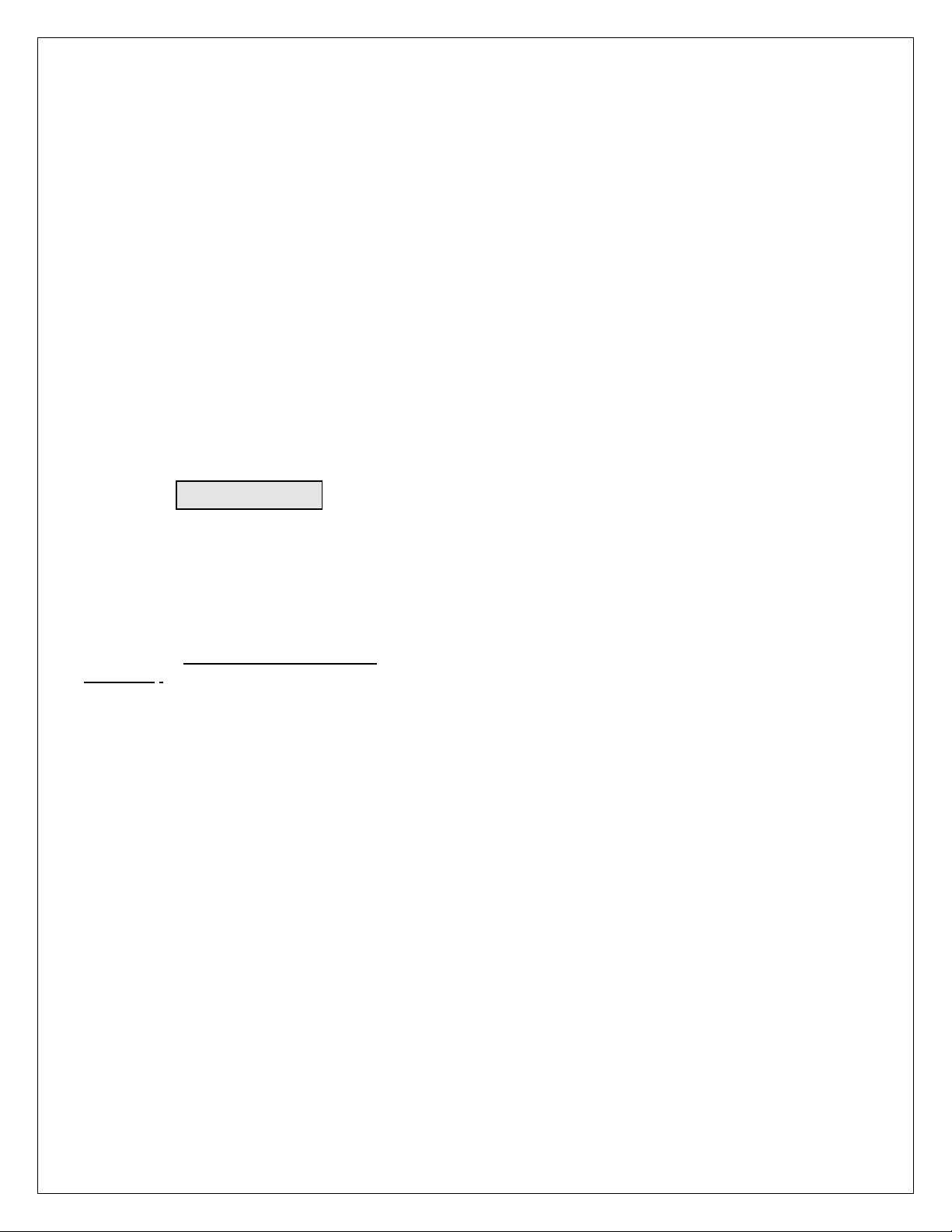
EXTERNAL INTERLOCK: The X-ray cannot be
enabled unless the external interlock is closed by
connecting J2-11 to J2-12. During high voltage
operation, opening the interlock circuit will cause the
High Voltage to be disabled. Interlock status
indication via RS-232 interface at J3.
IMPORTANT
This control signal is not a safety
interlock and should not be used for
protection from X-ray generation for
safety purposes.
HV ON LAMP RELAY: When X-ray ON command
is enabled a NO and a NC relay contact closure will
occur at connector J2. Refer to pin assignments
datasheet SHV#128118-001 and specification for
contact ratings.
OIL TEMPERATURE MONITOR: Provides
remote oil temperature monitor via RS-232 digital
interface port at J3 on front cover.
PS Fault Indication: PS Faults an open collector
output on J2-1, indicates that a faults has occurred.
High = no faults.
X-ray On Indication: X-ray On Signal is an open
collector output on J2-14, indicates that a faults has
occurred. High = X-ray off
Page 9

XRB80PN100HR MONOBLOCK® MANUAL 4 118169-001 REV C
1.3 System Status and Fault
Diagnostic Display
If a fault occurs, the power supply will revert to the
POWER DOWN mode indicated by extinguishing of Xray ON led and via RS-232 as HV OFF. To reset a fault, a
clear command or X-ray ON command must be sent via
RS-232.
EXTERNAL INTERLOCK FAULT: Indicates that
the high voltage supply is inhibited by external
interlock protection circuitry solely via RS-232
communication as (ARG 8) Open Interlock.
OVERVOLTAGE: Indicates the over voltage
protection circuitry has caused the high voltage to
turn off. Over voltage protection is internally set to
88kv. This fault is indicated by OV led status on the
front cover and via RS-232 as (ARG 3), Over
Voltage.
OVER CURRENT FAULT: Indicates the output
current has exceeded 2.20ma or if the allowable
percentage of error between actual and programmed
emission currents is exceeded resulting in the HV to
be turned off. This fault is indicated by illumination
of OC led status on the front cover and via RS-232 as
(ARG 5) Over Current.
ARC FAULT: On the standard unit indicates that an
arc has occurred. This fault is indicated by
momentary (~ 1 sec) illumination of ARC FLT led
status on front cover and via RS-232 as (ARG 1) Arc.
Occurrences of four arcs with in a period of ten
seconds will shutdown the high voltage. This fault is
indicated by illumination of ARC FLT led status on
front cover and via RS-232 as (ARG 1) Arc.
UNDER VOLTAGE: Indicates a failure in the
voltage regulation circuitry. This fault occurs when
there is a lack of output power to maintain regulation
and will result in shutdown of the HV. This fault is
indicated by illumination of UV led status on the
front cover and via RS-232 as (ARG 4) Under
Voltage.
UNDER CURRENT: Indicates failure in the current
regulation circuitry. This fault occurs when the
allowable percentage of error between actual and
programmed emission currents is exceeded, due to
the actual emission current being less than the
programmed level. This fault does not shutdown the
HV, it is indicated by illumination of UC led status on
front cover and via RS-232 as (ARG 6) Under
Current.
OVER TEMPERATURE: Indicates that the internal
oil temperature has exceeded 66 deg C. This could be
either caused by a failure in the customer supplied
cooling fan that would cause the oil temperature to
exceed 65 deg C or the ambient temperature has
exceeded 40 deg C, resulting in shutdown of HV.
This fault is indicated by OT led status on the front
cover and via RS-232 as (ARG 6) Over Temperature.
POWER ON LED: When input power is applied to
the unit it is indicated by the POWER led being
illuminated.
X-ray On LED: when the high voltage status is
“On” state it is indicated by X-RAY ON led status on
the front cover.
WATCHDOG TIMER: Indicates the host computer
has lost communication and with the HVPS system
for a period greater than ten second. This feature is
enabled via RS-232 host command. This fault is
indicated via RS-232 as (ARG 5) Watchdog Timeout. See digital manual for details.
OVER POWER FAULT: Indicates the output
power has exceeded 107watts. This fault is indicated
by the illumination of both the UC and OC led status
on the front cover an, OP fault via RS-232 as (ARG
9) Over Power.
Page 10
XRB80PN100HR MONOBLOCK® MANUAL 5 118169-001 REV C
1.4 Interpreting the Model Number
The model number of the power supply describes its
capabilities. After the series name is:
1. Maximum voltage (in kV).
2. Polarity of the unit: (PN) Bi Polar
3. The maximum output (in watts).
4. Options
5. Custom model number
XRB 80 PN 100 HR / XX / X (#)
XRB80PN100HR
Series
Name
Maximum
Voltage
Bi Polar
Output
Polarity
Maximum
Power
Custom
“X”
Number
Options
See datasheet
Page 11
XRB80PN100HR MONOBLOCK® MANUAL 6 118169-001 REV C
Chapter 2
INSPECTION & INSTALLATION
nitial inspection and preliminary checkout procedures
are recommended. For safe operation, please follow
the step-by-step procedures described in Chapter 3,
Operating Systems.
2.1 Initial Inspection
Inspect the package exterior for evidence of damage due
to handling in transit. Notify the carrier and Spellman
immediately if damage is evident. Do not destroy or
remove any of the packing material used in a damaged
shipment.
After unpacking, inspect the panel and chassis for visible
damage.
Fill out and mail the Warranty Registration card
accompanying the unit. Standard Spellman XRB80HR
MONOBLOCK Series high voltage power supplies and
components are covered by warranty.
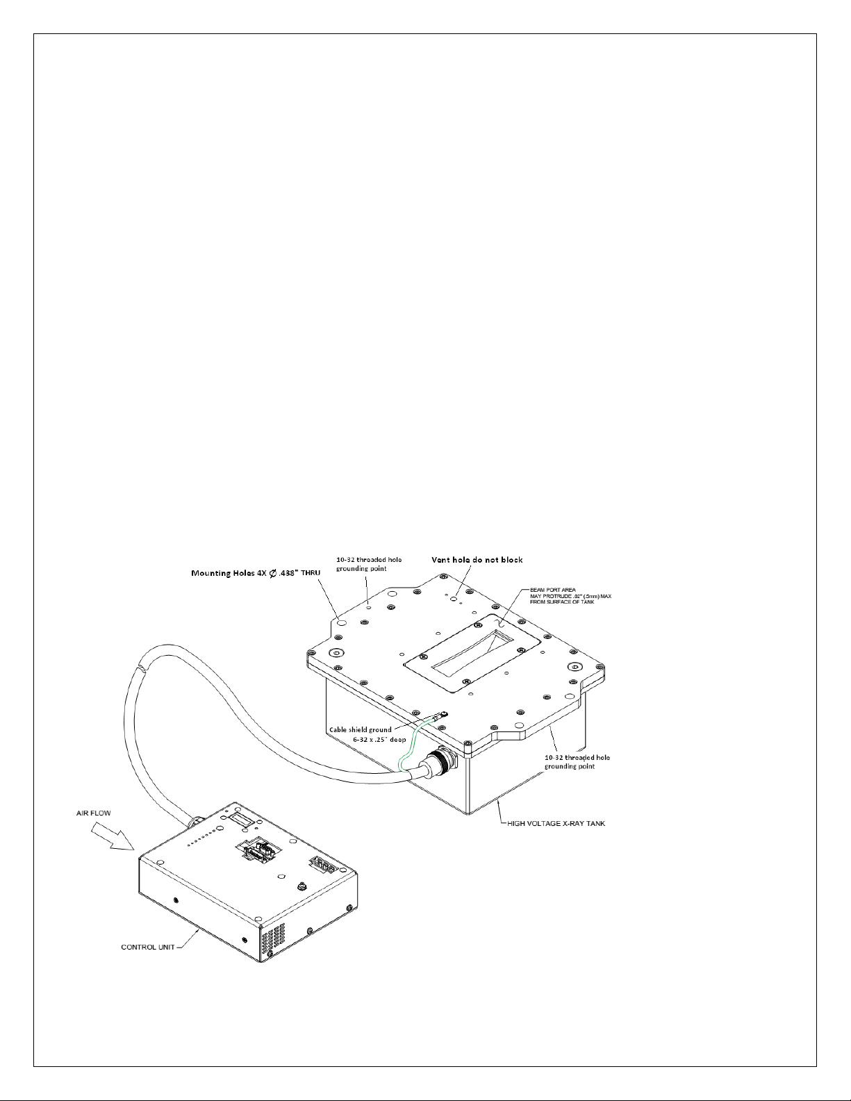
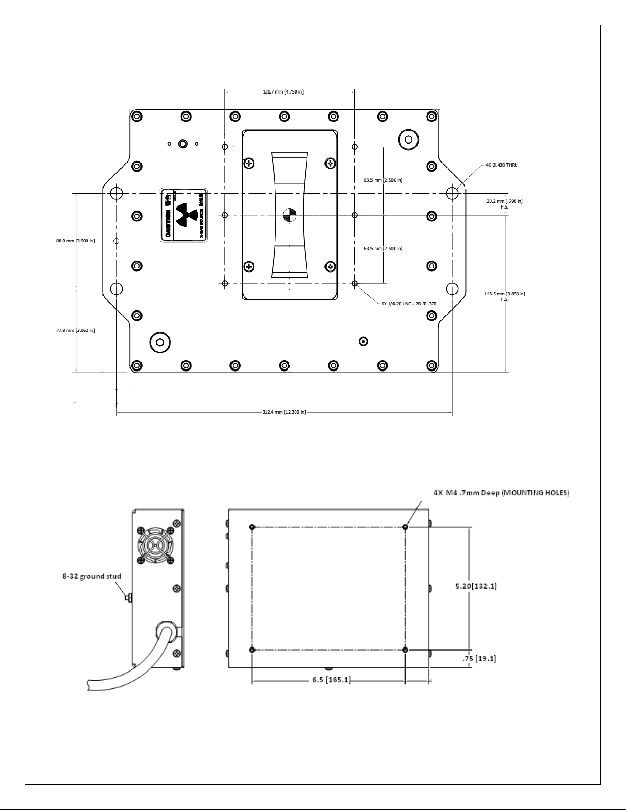
2.2 Installation
The unit can be mounted in any position. Four, .438” thru
mounting holes are provided on the Tank flanges shown
below. For Exit port collimation mounting six ¼ -20 UNC
2B holes .370” deep are provided.
The Control assemble has four, M4 threaded holes .7mm
deep.
Do not block the vent holes in the top cover as indicated.
I
Page 12
XRB80PN100HR MONOBLOCK® MANUAL 7 118169-001 REV C
Page 13
XRB80PN100HR MONOBLOCK® MANUAL 8 118169-001 REV C
Chapter 3
OPERATING INSTRUCTIONS
3.1 Operation
THIS EQUIPMENT GENERATES DANGEROUS
VOLTAGES THAT MAY BE FATAL.
PROPER GROUNDING OF ALL HIGH VOLTAGE
EQUIPMENT IS ESSENTIAL.
WARNING X-RAY RADIATION EXPOSURE IS
HAZARDOUS
Failure to follow these procedures may void the warranty.
Check the input voltage rating on the nameplate of the
supply and make certain that this is the rating of the
available power source. Spellman XRB80HR
MONOBLOCK XRB80PN100HR operates on 90264VAC, single phase 50 or 60Hz.
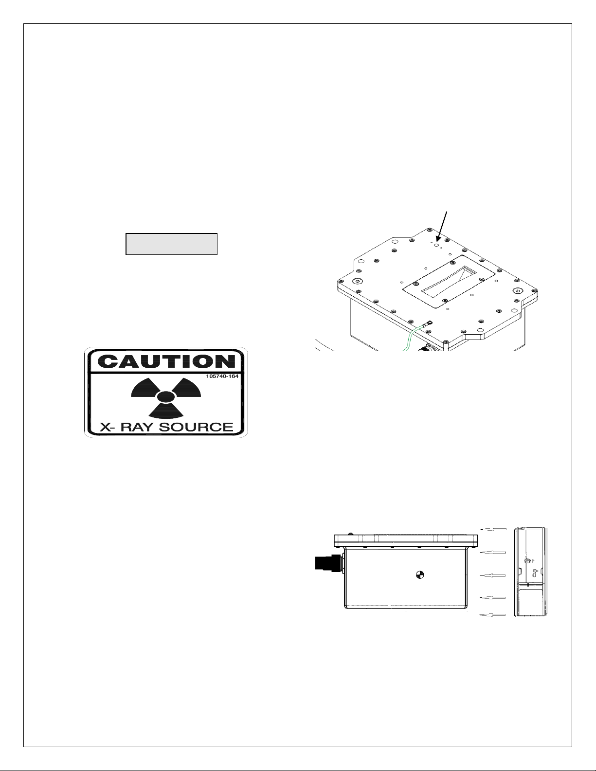
Bellow Vent hole:
Do not block or insert anything into the vent hole located
on top cover as shown. This hole provide venting for the
internal bellows that is used to compensate for the
expansion of the oil as the oil temperature varies.
Do not block vent holes on the cover
Cooling:
A customer supplied 250 CFM fan should be used to
maintain safe operating temperature for XRB80HR
MONOBLOCK X-ray generator. The air flow should be
direct at side wall (opposite the interface connector) and
across both the top and the bottom of the tank as shown
below. During operation the internal oil temperature
should be below 55 deg C and should not exceed 65 deg
C. See below Figure for fan location.
WARNING
Page 14
XRB80PN100HR MONOBLOCK® MANUAL 9 118169-001 REV C
BEFORE CONNECTING THE POWER SUPPLY
TO THE AC LINE, FOLLOW THIS PROCEDURE.
1) PROPER GROUNDING TECHNIQUES: The Tank
of the X-ray Generator must be grounded, by using the
ground connected to the provided 10-32 threaded hole on
the tank cover. The Controller of the X-ray Generator
must be grounded, by using the ground connected to the
provided ground stud located on the cover of the Control
Assembly.
Note: For optimal EMC results the Tank and Controller
should be mounted to the same ground plane, if not a
ground wire (preferably a braided wire) should be
connected between the tank and the controller.
2) Plug Controller interface cable into the Tank of the XRay Generator. Connect interface cable Ground shield
wire to the Tank with provided 6-32 threaded hole.
3) ENSURE THAT THE EXIT PORT IS PROPERLY
MATED TO COLLIMATOR OR SATISFACTORILY
SHIELDED WITH LEAD PLUG TO LIMIT
EXPOSURE TO LEAKAGE RADIATION.
X-ray Safety Procedures must be followed when
testing this unit. The XRB80PN100HR is capable
of producing Lethal Voltages and X-ray
Radiation. Only proceed with operation of the
HVPS after
a) consulting with the Manufacturer and
verification of X-ray setup for the proper
precautions.
b) reading this entire document.
NEVER OPERATE THIS UNIT WITH AN OPEN
X-RAY EXIT PORT.
It is recommended not to allow leakage radiation
exceeding 0.5mR/hr at 5cm from any surface of
the XRB80HR MONOBLOCK.
3.2 Signal and Power Interface
Connections
1) Connect Ground wire to the stud located on the cover
of the Control Assembly marked Ground.
2) Connect digital signal interface RS-232 communication
cable from the host computer to the J3 connector on
Control Assembly.
3) Close external Interlock by connecting J2-11 to J2-12
through a dry contact. See Figure 3.1 for wiring diagram
and specifications.
4) Connect 90 - 264VAC line to J1 use Phoenix contact
connector block # 1805990(not provided) Pin 1= earth
Pin 2 =Line and Pins 3= Neutral. Make sure AC line
voltage is OFF when connecting to the unit.
5) Determine unit’s idle time and refer to Table 2 for
seasoning procedure. If in doubt, use the longest
seasoning schedule.
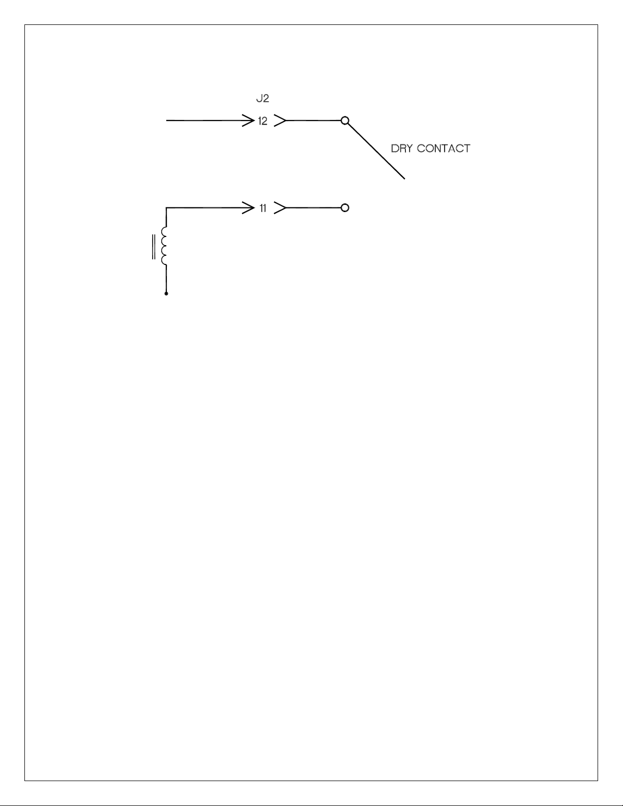
3.3 Analog monitors
1) Monitor kV output by measuring J2-8(reference to
signal ground J2-10), 0-9.00v (0-80kV).
2) Monitor ma output by measuring J2-6 (reference to
signal ground J2-10), 0-9.00V (0-2.00mA)
See Figure 3.3 for wiring diagram and specifications.
3.4 Local Mode (Analog enable)
1) In local mode, to enable X-ray On connect J2-13 to J215 through a dry contact. The external interlock must also
be close for the X-ray to enable. This feature is disable
after Digital enable command is sent.
See Figure 3.4 for wiring diagram and specifications.
3.5 Remote Mode (Digital control)
G.U.I and operation instruction
1) Install the G.U.I software to the host computer (See CD
with GUI).
2) Start the G.U.I.
3) Read agreement then click AGREE.
4) Operate the unit using GUI. For instruction on GUI
operation, see the “XRB80HR GUI INSTRUCTION”
document provided on with the GUI on the CD.
3.6 X-ray Tube Seasoning Process
Caution: To prevent premature degradation of the X-ray
tube, it is highly recommended to run the seasoning
process if the unit has not been turned on for more than 3
days. See Table 2.
WARNING
Page 15
XRB80PN100HR MONOBLOCK® MANUAL 10 118169-001 REV C
RELAY
Figure 3.1 Interlock Logic Control
____________________________________________________________________________________________
Page 16
XRB80PN100HR MONOBLOCK® MANUAL 11 118169-001 REV C
Figure 3.3 Remote Monitoring
____________________________________________________________________________________________
Figure 3.4 Local Enable Logic Control
Page 17
XRB80PN100HR MONOBLOCK® MANUAL 12 118169-001 REV C
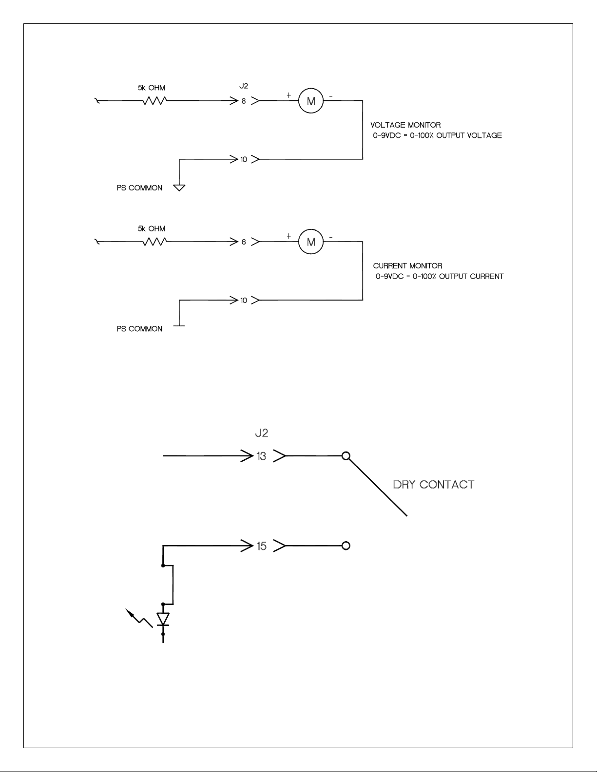
Chapter 4
Diagnostics
Fault/Symptom
Possible Cause
OV led illuminated and Over
voltage fault at RS-232
resulting in HV Status Off.
kV programming set greater
than 80kV.
UV led illuminated and Under
Voltage fault at RS-232
resulting in HV Status Off.
AC input voltage lower than
minimum specified.
OC led illuminated and Over
Current fault at RS-232
resulting in HV Status Off.
mA programming greater than
2.00mA.
UC led illuminated and Under
current fault at RS-232
resulting in HV Status Off.
kV programming is less than
35kV or AC input voltage
below spec.
OT led illuminated and Over
temperature fault at RS-232
resulting in HV Status Off.
Internal oil temperature is
above 65 deg C, could be
caused by operation at
ambient temperature greater
than 40°C or failure of a
customer supplied cooling fan.
ARC FLT led momentarily
illuminated and a momentary
Arc fault at RS-232 resulting
in HV Status staying ON.
Occurrence of tube arc. Refer
to tube re-seasoning procedure
Table 2 and idle times.
ARC FLT led illuminated and
Arc fault at RS-232 resulting
in HV Status OFF
At least four arcs occurred in a
ten second period causing
shutdown. Clear fault and
send X-ray command. Refer to
tube re-seasoning procedure
Table 2 and idle times. If
problem continues contact
Spellman service department.
Over Power
Kv and ma programming
exceeded 107W.Reduce
programming <100W.
Unit will not Enable
Interlock open and/or tank to
controller interface cable
unplugged.
TABLE 1
Page 18

XRB80PN100HR MONOBLOCK® MANUAL 13 118169-001 REV C
Chapter 5
FACTORY SERVICE
5.1 Warranty Repairs
During the Warranty period, Spellman will repair all units
free of charge. The Warranty is void if the unit is worked
on by other than Spellman personnel. See the Warranty in
the rear of this manual for more information. Follow the
return procedures described in Section 5.2. The customer
shall pay for shipping to and from Spellman.
5.2 Factory Service Procedures
Spellman has a well-equipped factory repair department.
If a unit is returned to the factory for calibration or repair,
a detailed description of the specific problem should be
attached.
For all units returned for repair, please obtain an
authorization to ship from the Customer Service
Department, either by phone or mail prior to shipping.
When you call, please state the model and serial numbers,
which are on the plate on the rear of the power supply,
and the purchase order number for the repair. A Return
Material Authorization Code Number (RMA Number) is
needed for all returns. This RMA Number should be
marked clearly on the outside of the shipping container.
Packages received without an RMA Number will be
returned to the customer. The Customer shall pay for
shipping to and from Spellman.
A preliminary estimate for repairs will be given by phone
by Customer Service. A purchase order for this amount is
requested upon issuance of the RMA Number. A more
detailed estimate will be made when the power supply is
received at the Spellman Repair Center. In the event that
repair work is extensive, Spellman will call to seek
additional authorization from your company before
completing the repairs.
5.3 Ordering Options and
Modifications
Many of the options can be retrofitted into Spellman’s
power supplies by our factory. For prices and
arrangements, contact the Spellman Sales Department.
5.4 Shipping Instructions
All power supplies returned to Spellman must be sent
shipping prepaid. Pack the units carefully and securely in
a suitable container, preferably in the original container, if
available. The power supply should be surrounded by at
least four inches of shock absorbing material. Please
return all associated materials, i.e. high voltage output
cables, interconnection cables, etc., so that we can
examine and test the entire system.
All correspondence and phone calls should be directed to:
Spellman High Voltage Electronics Corp.
475 Wireless Boulevard
Hauppauge, New York 11788
TEL: (631) 630-3000 FAX: (631) 435-1620
E-Mail: sales@Spellmanhv.com
Page 19

XRB80PN100HR MONOBLOCK® MANUAL 14 118169-001 REV C
RE-SEASONING PROCESS
for
XRB80PN100HR
Parameters
Step 1
Step 2
Step 3
Step 4
Step 5
Step 6
Step 7
Step 8
Step 9
Step 10
Voltage (kV)
40
45
50
55
60
65
70
70
75
80
Current (uA)
250
400
550
700
850
1000
1150
1250
1250
1250
For units with
idle time >3
months
5 min
5 min
5 min
5 min
5 min
5 min
5 min
5 min
5 min
5 min
For units with
idle time of 1-3
months
60 sec
60 sec
60 sec
60 sec
60 sec
60 sec
60 sec
60 sec
60 sec
60 sec
For units with
idle time of 2-30
days
30 sec
30 sec
30 sec
30 sec
30 sec
30 sec
30 sec
30 sec
30 sec
30 sec
Daily turn on
3 sec
3 sec
3 sec
3 sec
3 sec
3 sec
3 sec
3 sec
3 sec
3 sec
TABLE 2
Page 20

To obtain information on Spellman’s product warranty please visit our website at:
http://www.spellmanhv.com/en/About/Warranty.aspx
Page 21

XRB80HR Digital Interface
Serial – RS-232
Copyright 2016, Spellman High Voltage Electronics Corporation. All Rights Reserved.
This information contained in this publication is derived in part from proprietary and patent data. This information h as
been prepared for the express purpose of assisting operating and maintenance personnel in the efficient use of the
model described herein, and publication of this information does not convey any right to reproduce it or to use it for
any purpose other than in connection with installation, operation, and maintenance of the equipment described.
118170-001 REV A
475 Wireless Boulevard • Hauppauge, New York 11788, USA • www.spellmanhv.com • T:+1 631.630.3000 • F:+1 631.435.1620
Page 22

Changes
REVISION DATE DESCRIPTION
1 10/13/16 Draft version
2 4/13/17 Update Photo & remove 5.7
118170-001 REV A Page 2 of 37
Page 23

Table Of Contents
1.0 Scope ....................................................................................................................... 4
2.0 Functional Description ........................................................................................... 4
3.0 Getting Started - Interface Wiring and Pin-outs ................................................... 4
3.1 RS232 Interface ..................................................................................................... 4
3.4 RS-232 Cabling ..................................................................................................... 5
4.0 Getting Started - Software ...................................................................................... 6
4.1 RS-232 .................................................................................................................. 6
5.0 Serial Commands – RS-232 .................................................................................... 8
5.1 Serial Interface Protocol ........................................................................................ 8
5.2 Command Arguments ............................................................................................ 8
5.3 Checksums ............................................................................................................ 8
5.4 Command Overview ............................................................................................ 10
5.5 Response Overview ............................................................................................. 11
5.6 Command Structure ............................................................................................ 13
6.0 SerialCommand Handling ..................................................................................... 37
6.1 Command Time out ............................................................................................. 37
6.2 Buffer Flushing .................................................................................................... 37
6.3 Hand shaking ....................................................................................................... 37
118170-001 REV A Page 3 of 37
Page 24

WARNING
THIS EQUIPMENT GENERATES DANGEROUS VOLTAGES THAT MAY BE FATAL.
PROPER GROUNDING OF ALL HIGH VOLTAGE EQUIPMENT IS ESSENTIAL.SEE 80kv
MONOBlOCK OWNERS MANUAL FOR PROPER GROUNDING TECHNIQUE AND SAFETY
PRECAUTIONS BEFORE APPLING AC INPUT POWER TO THE XRB UNIT.
TO PREVENT DAMAGE TO THE HOST COMPUTER THE COMPUTER SHOULD BE
GROUNDED TO THE SAME GROUND AS THE UUT.
This unit is capable of producing X-ray radiation, please proceed only after
proper precautions have been taken to prevent X-ray exposure.
1.0 SCOPE
This document applies to the communications interfaces on the XRB, assembly
460350-001.
2.0 FUNCTIONAL DESCRIPTION
The XRB provides 1 type of digital communications interface:
RS-232 on J3
3.0 GETTING STARTED - INTERFACE WIRING AND PIN-OUTS
3.1 RS232 INTERFACE
The RS232C interface has the following attributes:
115K bits per second
No Parity
8 Data Bits
1 Stop Bit
No handshaking
DB-9 connector as shown
Figure 1 – J3, RS-232 DB-9M pinout (front view)
118170-001 REV A Page 4 of 37
Page 25

PIN
DESCRIPTION
1 - 2
Tx Out
3
Rx In 4 -
5
Ground
6 - 7 - 8 - 9
-
PC to XRB Board Cable Details
PC Connector (DB-9 Female)
XRB Connector (DB-9 Male)
Pin 2: RX In
Pin 2: TX Out
Pin 3: TX Out
Pin 3: RX In
Pin 5: Ground
Pin 5: Ground
3.4 RS-232 CABLING
A standard shielded RS-232 cable is used to connect the XRB serial port
to the serial port on a standard personal computer. Please refer to the
following chart.
118170-001 REV A Page 5 of 37
Page 26

4.0 GETTING STARTED – SOFTWARE
The following sections detail how to create software to interface to the XRB
communications interfaces.
4.1 RS-232
The RS-232 interface makes use of a standard ‘command/response’
communications protocol. See section 5.0 for the syntax of the serial
interface protocol. The programmer should also review section 4.3 for
programming considerations for the RS-232 interface.
All software that addresses the RS-232 interface must adhere to the
following parameters:
A default Baud rate of 115.2K bps
No Parity
8 Data Bits
1 Stop Bit
No handshaking
4.1.1 Enabling Communications Objects in Visual Basic for RS-232
Communications in Microsoft Visual Basic 6.0 are directed to a control
that abstracts the port. In the case of serial and USB we need
Microsoft Comm Control 6.0. To enable this in your VB 6 project, go to:
Project -> Components
Then in the list make sure that Microsoft Comm Control 6.0 has a
check next to it. The Comm Control Object should then appear in your
toolbox. It will have an icon of a telephone and will be named:
MSComm. This can be dragged and dropped into your application.
You will then need to set the object’s properties.
4.1.2 Configuring Communications in Visual Basic for RS-232
In order to configure the MSComm Object, first you must initialize it
in the Object properties:
Settings 115200,n,8,1
Handshaking 0 – comNone
The application can be set to either default to a specific COM Port
or the End User can be allowed to choose one for the particular
118170-001 REV A Page 6 of 37
Page 27

PC. For the “Default” scenario, include the following commands in
the Form_Load() routine:
MSComm1.CommPort = portNumber
MSComm1.PortOpen = True
118170-001 REV A Page 7 of 37
Page 28

5.0 SERIAL COMMANDS – RS-232
5.1 SERIAL INTERFACE PROTOCOL
Serial communications will use the following protocol:
There are two categories of commands from the host computer to the tank.
1. Commands that have an argument.
2. Commands that do not have an argument.
The syntax of commands that have an argument is:
<STX>CMD<SP>ARG;<CSUM><CR><LF>
The syntax of commands that do not have an argument is:
<STX>CMD;<CSUM><CR><LF>
The specification of the above symbols is as follows:
<STX> = 1 ASCII 0x02 Start of Text character
<CMD> = 3 - 4 ALPHA ASCII characters representing the command ID
<SP> = 1 ASCII 0x20 character
<ARG> = Command Argument
<;> = 1 ASCII 0x3B semicolon character 0x3B
<CSUM> = Checksum (see section 5.3 for details)
<CR> = Carriage return character 0x0D.
<LF> = Line feed character 0x0A
5.2 COMMAND ARGUMENTS
The format of the numbers is a variable length string. To represent the number
42, the string ‘42’, ‘042’, or ‘0042’ can be used. This being the case, commands
and responses that carry data are variable in length.
5.3 CHECKSUMS
The checksum is computed as follows:
Add the <CMD>, <,>, and <ARG> bytes excluding the <STX> byte into
a 16 bit (or larger) word. The bytes are added as unsigned integers.
Take the 2’s compliment (negate it) and add the value of 1 to the resulting
value.
Truncate the result down to the eight least significant bits.
Clear the most significant bit (bit 7) of the resultant byte, (bitwise AND with
0x7F).
118170-001 REV A Page 8 of 37
Page 29

Set the next most significant bit (bit 6) of the resultant byte (bitwise OR
with 0x40).
Using this method, the checksum is always a number between 0x40 and 0x7F.
The checksum can never be confused with the <STX> or <ETX> control
characters, since these have non-overlapping ASCII values.
If the DSP detects a checksum error, the received message is ignored – no
acknowledge or data is sent back to the host. A timeout will act as an implied
NACK.
CheckSum Calulate Example for VREF command:
VREF<SP>4095; = 0x260H – total sum in Hex.
= 0xD9FH – negate.
= 0xDA0H – add one.
= 0xA0H – truncate down to 8 least significant bits.
= 0x20H – clear bit 7.
= 0x60H – set bit 6.
CheckSum = 0x60H
The following is sample code, written in Visual Basic, for the generation of
checksums:
Public Function ProcessOutputString(outputString As String) As String
Dim i As Integer
Dim CSb1 As Integer
Dim CSb2 As Integer
Dim CSb3 As Integer
Dim CSb$
Dim X
X = 0
For i = 1 To (Len(outputString)) 'Starting with the CMD character
X = X + Asc(Mid(outputString, i, 1)) 'adds ascii values together
Next i
CSb1 = 256 - X
CSb2 = 127 And (CSb1) 'Twos Complement
CSb3 = 64 Or (CSb2) 'OR 0x40
CSb$ = Chr(Val("&H" & (Hex(CSb3))))
ProcessOutputString = Chr(2) & outputString & CSb$ & Chr(13) & Chr(10)
End Function
118170-001 REV A Page 9 of 37
Page 30

5.4 COMMAND OVERVIEW
Command Name
<CMD>
<ARG>
RANGE
Program kV
VREF
1-4 ASCII
0-4095
Program mA
IREF
1-4 ASCII
0-4095
Request kV
Sepoint
VSET
None
-
Request mA
Sepoint
ISET
None
-
Request kV
Monitor
VMON
None
-
Request mA
Monitor
IMON
None
-
Request Filament
Monitor
FMON
None
-
Turn XRAY On/Off
ENBL
1 ASCII
0-1
Enable Comm
Watchdog
WDTE
1 ASCII
0-1
Tickle Comm
Watchdog
WDTT
None
-
Reset Faults
CLR
None
-
Request Faults
FLT
None
-
Read XRAY Status
STAT
None
-
Request Software
Version
FREV
None
-
Request Voltage
Scaling
SLVR
None
-
Request Current
Scaling
SLIR
None
-
Request Model
Number
MODR
None
-
Request Hardware
Version
HWVR
None
-
Request Software
Build Version
SOFT
None
-
Request –15V
LVPS
LVPS
None
-
Request Tank
Temperature
TEMP
None
-
Program Baud
Rate
BAUD 1 1-2
118170-001 REV A Page 10 of 37
Page 31

Serial Number
Program
SNUS
16 ASCII
character
string
Request Serial
Number
SNUR
16 ASCII
character
string
Response Name
<CMD>
Response
Request kV
Monitor
VMON
6-9
Request mA
Monitor
IMON
6-9
Request kV
Setpoint
VSET
6-9
Request mA
Setpoint
ISET
6-9
Request Filament
Monitor
FMON
6-9
Request Faults
FLT
13
Read XRAY Status
STAT
6
Request Software
Version
FREV
16
Request Voltage
Scaling
SLVR
9
Request Current
Scaling
SLIR
9
Request Model
Number
MODR
6-15
Request Hardware
Version
HWVR
8
Request Software
Build Version
SOFT
9-10
Request –15V
LVPS
LVPS
6-9
5.5 RESPONSE OVERVIEW
The command responses will follow the same format as outlined above in
section 5.1. This list is comprised of Commands with complex responses
only. Commands using a simple response will use the <;> character
(ASCII 0x3B) as a “Success” response. These responses will be 5 ASCII
characters in length.
118170-001 REV A Page 11 of 37
Page 32

Request Tank
Temperature
TEMP
6-9
118170-001 REV A Page 12 of 37
Page 33

5.6 COMMAND STRUCTURE
5.6.1 Program kV
Description:
The host requests that the firmware change the setpoint of kV.
Direction:
Host to supply
Syntax:
<STX><VREF><SP><ARG><;><CSUM><CR><LF>
Where:
<ARG> = 0 - 4095 in ASCII format
Example:
<STX><VREF><SP><4095><;><CSUM><CR><LF>
Response:
<STX><;><CSUM><CR><LF>
See 5.6.15 for voltage scaling
118170-001 REV A Page 13 of 37
Page 34

5.6.2 Program mA
Description:
The host requests that the firmware change the setpoint of mA.
Direction:
Host to supply
Syntax:
<STX><IREF><SP><ARG><;><CSUM><CR><LF>
Where:
<ARG> = 0 - 4095 in ASCII format
Example:
<STX><IREF><SP><4095><;><CSUM><CR><LF>
Response:
<STX><;><CSUM><CR><LF>
See 5.6.16 for current scaling
118170-001 REV A Page 14 of 37
Page 35

5.6.3 Request kV Monitor
Description:
The host requests that the firmware report kV monitor.
Direction:
Host to supply
Syntax:
<STX><VMON><;><CSUM><CR><LF>
Example:
<STX><VMON><;><CSUM><CR><LF>
Response:
<STX>< ARG><;><CSUM><CR><LF>
Where:
<ARG>=0-4095 in ASCII format representing unscaled value.
Example:
<STX><4095><;><CSUM><CR><LF>
118170-001 REV A Page 15 of 37
Page 36

5.6.4 Request kV Setpoint
Description:
The host requests that the firmware report kV setpoint.
Direction:
Host to supply
Syntax:
<STX><VSET><;><CSUM><CR><LF>
Example:
<STX><VSET><;><CSUM><CR><LF>
Response:
<STX>< ARG><;><CSUM><CR><LF>
Where:
<ARG>=0-4095 in ASCII format representing unscaled value.
Example:
<STX><4095><;><CSUM><CR><LF>
118170-001 REV A Page 16 of 37
Page 37

5.6.5 Request mA Setpoint
Description:
The host requests that the firmware report mA setpoint.
Direction:
Host to supply
Syntax:
<STX><ISET><;><CSUM><CR><LF>
Example:
<STX><ISET><;><CSUM><CR><LF>
Response:
<STX>< ARG><;><CSUM><CR><LF>
Where:
<ARG>=0-4095 in ASCII format representing unscaled value.
Example:
<STX><4095><;><CSUM><CR><LF>
118170-001 REV A Page 17 of 37
Page 38

5.6.6 Request mA Monitor
Description:
The host requests that the firmware report mA monitor.
Direction:
Host to supply
Syntax:
<STX><IMON><;><CSUM><CR><LF>
Example:
<STX><IMON><;><CSUM><CR><LF>
Response:
<STX>< ARG><;><CSUM><CR><LF>
Where:
<ARG>=0-4095 in ASCII format representing unscaled value.
Example:
<STX><4095><;><CSUM><CR><LF>
118170-001 REV A Page 18 of 37
Page 39

5.6.7 Request Filament Monitor
Description:
The host requests that the firmware report Filament monitor.
Direction:
Host to supply
Syntax:
<STX><FMON><;><CSUM><CR><LF>
Example:
<STX><FMON><;><CSUM><CR><LF>
Response:
<STX>< ARG><;><CSUM><CR><LF>
Where:
<ARG>=0-4095 in ASCII format representing unscaled value.
Example:
<STX><4095><;><CSUM><CR><LF>
118170-001 REV A Page 19 of 37
Page 40

5.6.8 Turn XRAYS On/Off
Description:
The host requests that the firmware to turn XRAY On/Off.
Direction:
Host to supply
Syntax:
<STX><ENBL><SP><ARG><;><CSUM><CR><LF>
Where:
<ARG> 1 = XRAY On, 0 = XRAY Off in ASCII format
Example:
<STX><ENBL><SP><1><;><CSUM><CR><LF>
Response:
<STX><;><CSUM><CR><LF>
118170-001 REV A Page 20 of 37
Page 41

5.6.9 Enable Commuunication Watchdog
Description:
The host requests that the firmware to enable communication watchdog.
Direction:
Host to supply
Syntax:
<STX><WDTE><SP><ARG><;><CSUM><CR><LF>
Where:
<ARG> 1 = Enable Watchdog, 0 = Disable Watchdog
Example:
<STX><WDTE><SP><1><;><CSUM><CR><LF>
Response:
<STX><;><CSUM><CR><LF>
118170-001 REV A Page 21 of 37
Page 42

5.6.10 Tickle Communication Watchdog
Description:
The host requests that the firmware reset communictation watchdog timer.
Direction:
Host to supply
Syntax:
<STX><WDTT><;><CSUM><CR><LF>
Example:
<STX><WDTT><;><CSUM><CR><LF>
Response:
<STX><;><CSUM><CR><LF>
118170-001 REV A Page 22 of 37
Page 43

5.6.11 Reset Faults
Description:
The host requests that the firmware resets all Fault messages and
indicators.
Syntax:
<STX><CLR><;><CSUM><CR><LF>
Example:
<STX><CLR><;><CSUM><CR><LF>
Response:
<STX><;><CSUM><CR><LF>
118170-001 REV A Page 23 of 37
Page 44

5.6.12 Request Faults
Description:
The host requests that the firmware report Faults.
Direction:
Host to supply
Syntax:
<STX><FLT><;><CSUM><CR><LF>
Example:
<STX><FLT><;><CSUM><CR><LF>
Response:
<STX><ARG1><ARG2><ARG3><ARG4><ARG5><ARG6><ARG7>
<ARG8><ARG9><;><CSUM><CR><LF>
Where:
<ARGx> 1 = Fault, 0 = No Fault in ASCII format
ARG1 = ARC
ARG2 = Over Temperature
ARG3 = Over Voltage
ARG4 = Under Voltage
ARG5 = Over Current
ARG6 = Under Current
ARG7 = Watchdog Time-out
ARC8 = Open Interlock
ARC9 = Over Power
Example:
<STX><100010011><;><CSUM><CR><LF>
118170-001 REV A Page 24 of 37
Page 45

5.6.13 Request XRAY Status
Description:
The host requests that the firmware read the XRAY status.
Direction:
Host to supply
Syntax:
<STX><STAT><;><CSUM><CR><LF>
Example:
<STX><STAT><;><CSUM><CR><LF>
Response:
<STX><ARG><;><CSUM><CR><LF>
Where ARG is status. A 1 indicates XRAY On. A 0 indicates XRAY Off.
Example:
<STX><1><;><CSUM><CR><LF>
118170-001 REV A Page 25 of 37
Page 46

5.6.14 Request DSP Software Part Number/Version
Description:
The host requests that the firmware sends the DSP firmware.
Direction:
Host to supply
Syntax:
<STX><FREV><;><CSUM><CR><LF>
Example:
<STX><FREV><;><CSUM><CR><LF>
Response:
<STX>< ARG><;><CSUM><CR><LF>
Where:
<ARG> consists of eleven ASCII characters representing the current
firmware part number/version. The format is SWM9999-999.
Example:
<STX><SWM9999-999><;><CSUM><CR><LF>
118170-001 REV A Page 26 of 37
Page 47

5.6.15 Request Voltage Scaling
Description:
The host requests requests that the firmware send the current unit voltage
scaling.
Direction:
Host to supply
Syntax:
<STX><SLVR><;><CSUM><CR><LF>
Example:
<STX><SLVR><;><CSUM><CR><LF>
Response:
<STX>< ARG><;><CSUM><CR><LF>
Where:
ARG = KV scaling (8889 = 88.89 kV)
Example:
<STX><8889><;><CSUM><CR><LF>
118170-001 REV A Page 27 of 37
Page 48

5.6.16 Request Current Scaling
Description:
The host requests requests that the firmware send the current unit current
scaling.
Direction:
Host to supply
Syntax:
<STX><SLIR><;><CSUM><CR><LF>
Example:
<STX><SLIR><;><CSUM><CR><LF>
Response:
<STX>< ARG><;><CSUM><CR><LF>
Where:
ARG = mA scaling (2220 = 2.220 mA)
Example:
<STX><1388><;><CSUM><CR><LF>
118170-001 REV A Page 28 of 37
Page 49

5.6.17 Request Model Number
Description:
The host requests that the firmware sends the unit model number
Direction:
Host to supply
Syntax:
<STX><MODR><;><CSUM><CR><LF>
Example:
<STX><MODR><;><CSUM><CR><LF>
Response:
<STX>< ARG><;><CSUM><CR><LF>
Where:
<ARG> consists of one to ten ASCII characters representing the model
number. The format is XBR80N100 or CB for cone beam option
Example:
<STX><XBR80N100><;><CSUM><CR><LF>
118170-001 REV A Page 29 of 37
Page 50

5.6.18 Request Hardware Version
Description:
The host requests that the firmware sends the hardware version.
Direction:
Host to supply
Syntax:
<STX><MODR><;><CSUM><CR><LF>
Example:
<STX><MODR><;><CSUM><CR><LF>
Response:
<STX>< ARG><;><CSUM><CR><LF>
Where:
<ARG> consists of 3 ASCII characters representing the hardware version.
The format is ANN, where A is an alpha character and N is a numeric
character
Example:
<STX><A01><;><CSUM><CR><LF>
118170-001 REV A Page 30 of 37
Page 51

5.6.19 Request Software Build Version
Description:
The host requests that the firmware sends the hardware version.
Direction:
Host to supply
Syntax:
<STX><SOFT><;><CSUM><CR><LF>
Example:
<STX><SOFT><;><CSUM><CR><LF>
Response:
<STX>< ARG><;><CSUM><CR><LF>
Where:
<ARG> consists of four to five ASCII characters representing the current
firmware build version. The format is 12345.
Example:
<STX><12345><;><CSUM><CR><LF>
118170-001 REV A Page 31 of 37
Page 52

5.6.20 Request –15V LVPS
Description:
The host requests that the firmware report –15V LVPS.
Direction:
Host to supply
Syntax:
<STX><LVPS><;><CSUM><CR><LF>
Example:
<STX><LVPS><;><CSUM><CR><LF>
Response:
<STX><ARG><;><CSUM><CR><LF>
Where:
<ARG>=0-4095 in ASCII format representing unscaled value.
To convert the unscaled value to voltage, use the equation below:
x = unscaled value.
Voltage = -(3972 - x) * 0.006224.
Example:
<STX><4095><;><CSUM><CR><LF>
118170-001 REV A Page 32 of 37
Page 53

5.6.21 Request Tank Temperature
Description:
The host requests that the firmware sends the tank temperature.
Direction:
Host to supply
Syntax:
<STX><TEMP><;><CSUM><CR><LF>
Example:
<STX><TEMP><;><CSUM><CR><LF>
Response:
<STX><ARG><;><CSUM><CR><LF>
Where:
<ARG>=0-956 in ASCII format representing 0 – 70.036 degrees C.
Example:
<STX><956><;><CSUM><CR><LF>
118170-001 REV A Page 33 of 37
Page 54

5.6.22 Program Baud Rate Select
Description:
The host requests that the firmware select a baud rate.
Direction:
Host to supply
Syntax:
<STX><BAUD><SP><ARG><;><CSUM><CR><LF>
Where:
<ARG> = 1 in ASCII format = 115200 Baud
<ARG> = 2 in ASCII format = 9600 Baud
Example:
<STX><BAUD><SP><1><;><CSUM><CR><LF>
Response:
<STX><;><CSUM><CR><LF>
118170-001 REV A Page 34 of 37
Page 55

5.6.23 PROGRAM SERIAL NUMBER
Description:
After the password command (PASS) and correct password are sent, the user
can program the unit serial number. Up to 16 alphanumeric characters are
allowed.
Password ARG = 1212
Direction:
Host to supply
Syntax:
<STX><SNUS><SP><ARG><;><CSUM><CR><LF>
Where:
<ARG> = 16 ASCII character string.
Example:
<STX><SNUS><SP><1234-ABCDE><;><CSUM><CR><LF>
Response:
<STX><;><CSUM><CR><LF>
118170-001 REV A Page 35 of 37
Page 56

5.6.24 REQUEST SERIAL NUMBER
Description:
The host requests that the firmware sends the current stored unit serial number.
The unit always replies with 16 characters. It is up to the Host to accept valid
character string.
Direction:
Host to supply
Syntax:
<STX><SNUR><;><CSUM><CR><LF>
Response:
<STX>< ARG><;><CSUM><CR><LF>
Where:
<ARG>= 16 ASCII character string.
Example:
<STX><1234-ABCDXXXXXXX><;><CSUM><CR><LF>
118170-001 REV A Page 36 of 37
Page 57

6.0 SERIAL COMMAND HANDLING
6.1 Command Time OutThe host computer should set a serial time
out at approximately 100mS. This allows the DSP to process the incoming
message, and transmit a response. The DSP will initiate a reply to
incoming messages in approximately 1-2mS, with a worst case of 5mS.
6.2 Buffer Flushing
The DSP will flush the incoming serial data buffer every time an STX is
received. This provides a mechanism to clear the receive buffer of partial
or corrupt messages.
6.3 Handshaking
The only handshaking implemented on the host interface, is built in to the
implementation of this protocol. That is, the host must initiate all
communications. If the supply receives a program command, an
acknowledge message is sent back to the host via the “;” message. If the
host does not receive an acknowledge within the time out window, the
host should consider the message lost or the device off-line.
Similarly, if the supply receives a request command, the requested data is
sent back to the host. If the host does not receive the requested data
within the time out window, the host should consider the message lost or
the device off-line.
This essentially uses the full-duplex channel in a half-duplex
communication mode.
118170-001 REV A Page 37 of 37
 Loading...