

Page 1

LPX200
Page 2
CAUTION: THIS EQUIPMENT PRODUCES
DO NOT OPERATE THIS EQUIPMENT WITHOUT
ASNT LEVEL 3 RADIOGRAPHIC CERTIFICATION
WWW.SPELLMANHV.COM
X-RAYS WHEN ENERGIZED!
FORMAL HARDWARE RAINING F ROM
SPELLMAN HIGH VOLTAGE ELECTRONICS.
IS HIGHLY RECOMMENDED.
Copyright 2000, Spellman High Voltage Electronics Corporation. All Rights Reserved.
This information contained in this publication is derived in part from proprietary and patent data. This information has
been prepared for the express purpose of assisting operating and maintenance personnel in the efficient use of the
model described herein, and publication of this information does not convey any right to reproduce it or to use it for
any purpose other than in connection with installation, operation, and maintenance of the equipment described.
118176-001 REV. A
Page 3
COPYRIGHT NOTICE
Spellman Valhalla 1 Commerce Park Valhalla, NY 10595
Phone: +1 914 686-3600 Fax: +1 914 686-5424
www.spellmanhv.com
This document is copyrighted by LORAD.
No part of this document may be reproduced, transmitted,
or copied without the express written permission of:
LPX-200
Industrial Imaging System
LPX-200 Industrial Imaging System
Copyright© 2002 by LORAD All rights reserved.
Operator’s Manual
Part Number 9-500-0200, Revision 2
Table of Contents
Copyright Notice
i
Page 4

LPX-200
Industrial Imaging System
This Page Is Intentionally Blank
ii
Table of Contents
Page 5

Chapter
1
LPX-200
Industrial Imaging System
Contents
INTRODUCTION & GENERAL INFORMATION
INTRODUCTION ..................................................................1-1
Intended Use......................................................................... 1-1
SYSTEM OVERVIEW ..........................................................1-1
The Control Unit................................................................... 1-2
The Tubehead ....................................................................... 1-2
The Cooling Unit
(liquid-cooled units only) ..................................................... 1-2
Legend - LPX-200 X-ray System ..........................................1-3
MANUAL OUTLINE.............................................................1-4
Chapter 1:
Introduction & General Information....................................1-4
Chapter 2:
Preparation For Use and Shipment ......................................1-4
Chapter 3:
Installing the LPX-200 ......................................................... 1-4
Chapter 4:
LPX-200 X-ray Controls & Indicators .................................1-4
Chapter 5:
LPX-200 X-ray System Operation........................................1-4
Section 6:
Routine Upkeep and Care .................................................... 1-4
SAFETY SUMMARY ............................................................1-5
Radiation Hazard .................................................................1-6
Lethal Voltages ..................................................................... 1-6
Badges .................................................................................. 1-6
Radiation Protection ............................................................ 1-6
Radiation Monitoring...........................................................1-6
Warm-Up Procedures ...........................................................1-6
Operation ............................................................................. 1-6
Cooling Unit Operation ....................................................... 1-6
Care in Handling.................................................................. 1-6
Table of Contents
iii
Page 6

LPX-200
Industrial Imaging System
PREPARATION FOR USE & SHIPMENT
UNP ACKING INSTRUCTIONS...........................................2-1
Reshipment Guidelines .........................................................2-1
Transporting the Unit ........................................................... 2-2
EQUIPMENT CHECKLISTS...............................................2-3
Checklist - Tubehead ............................................................ 2-3
Checklist - Standard Equipment........................................... 2-3
Checklist - Optional Equipment ........................................... 2-3
WARNINGS LABELS &
CONTROL NUMBERS .........................................................2-4
SPECIFICATIONS.................................................................2-5
Specifications - General System ...........................................2-5
Specifications - General Tubehead.......................................2-6
Specifications - Optional Tubehead .....................................2-6
Specifications - Control Unit................................................ 2-7
Specifications - Cooling Unit ............................................... 2-7
INSTALLING THE LPX-200 X-RAY SYSTEM
Chapter
2
Chapter
PRE-OPERATIONAL
CHECKS & INSPECTION ...................................................3-1
Check - Tubehead Gas Pressure........................................... 3-1
Check - Cooling Unit............................................................ 3-1
Check - Control Unit ............................................................3-1
SYSTEM SET UP PROCEDURES.......................................3-2
System Interconnections - Liquid Cooled.............................3-2
System Interconnections - Air Cooled ..................................3-3
Connecting to Power ............................................................ 3-4
EXTERNAL
INTERLOCK CONNECTIONS ...........................................3-4
iv
Table of Contents
3
Page 7

LPX-200
Industrial Imaging System
Chapter
4
LPX-200 X-RAY CONTROLS & INDICATORS
INTRODUCTION ..................................................................4-1
Overview - Control Unit.......................................................4-1
Legend - LPX-200 Control Unit ...........................................4-1
THE LIQUID
CRYSTAL DISPLA Y SCREENS ..........................................4-2
The Message / Mode LCD Display Screen........................... 4-3
FRONT PANEL
CONTROLS AND INDICAT ORS ........................................4-4
The MAINS Switch................................................................4-4
The MAINS ON Indicator.....................................................4-4
The SAFETY Switch..............................................................4-4
The kV SET Controls ............................................................ 4-4
The mA SET Controls ...........................................................4-4
The EXPOSURE SET Controls ............................................4-5
The UNITS Control...............................................................4-5
The TIME Control ................................................................4-5
The RESET Control ..............................................................4-5
The SCROLL Contr ol ........................................................... 4-6
The X-RAY ON Control ........................................................4-6
The X-RAY Indicator ............................................................ 4-6
The X-RAY OFF Control ...................................................... 4-6
Chapter
5
LPX-200 SYSTEM OPERATION
INTRODUCTION ..................................................................5-1
Pre-Operational Safety Precautions ....................................5-1
X-RA Y TUBE WARM UP ......................................................5-2
Autowarm Sequence : > 30 Days.........................................5-2
Autowarm Sequence : 7 - 30 Days ....................................... 5-3
Autowarm Sequence : 16 Hrs. - 7 Days ............................... 5-3
Autowarm Sequence : 8 Hrs. - 16 Hrs..................................5-4
Autowarm Sequence : 4 Hrs. - 8 Hrs....................................5-4
OPERATION -
LPX-200 X-RAY SYSTEM ....................................................5-5
Sequence of Operation ......................................................... 5-5
LPX-200 FAULT MESSAGES...............................................5-7
X-RA Y TUBE SEASONING .................................................5-8
Table of Contents
v
Page 8

LPX-200
Industrial Imaging System
LPX-200 ROUTINE UPKEEP & CARE
INTRODUCTION ..................................................................6-1
INSPECTION CHECKLISTS ..............................................6-1
Tubehead Checklist ..............................................................6-1
Control Unit Chec klist.......................................................... 6-2
Cooling Unit Checklist ......................................................... 6-2
Interconnecting Cables & Hose Checklist ...........................6-2
CLEANING THE
LPX-200 X-RAY UNIT ..........................................................6-3
Required Cleaning Materials ...............................................6-3
Cleaning the X-Ray Unit ...................................................... 6-3
TUBEHEAD MAINTENANCE ............................................6-4
Temperature Compensation.................................................. 6-4
Re-Pressurizing the Tubehead ..............................................6-5
Re-Filling the Tubehead .......................................................6-6
Cleaning - Control Unit Air Filter........................................6-6
COOLING UNIT UPKEEP...................................................6-7
Mixing & Adding Coolant Solution......................................6-7
Cleaning - Cooling Unit Air Filter.......................................6-7
Cleaning - Coolant Filter ..................................................... 6-8
Chapter
6
vi
Table of Contents
Page 9
Chapter 1:
Introduction and General Information
INTRODUCTION
This manual describes the LORAD LPX-200 Portable
Industrial X-ray Unit and explains the procedures to properly
set up, inspect, operate, and maintain this system.
Intended Use
The LPX-200 is designed to meet the needs of the commercial
NDT user. The system is intended for, but not limited to, the
inspection of materials for:
LPX-200
Industrial Imaging System
◆ defects
◆ inclusions
◆ cracks
◆ corrosion
◆ porosity
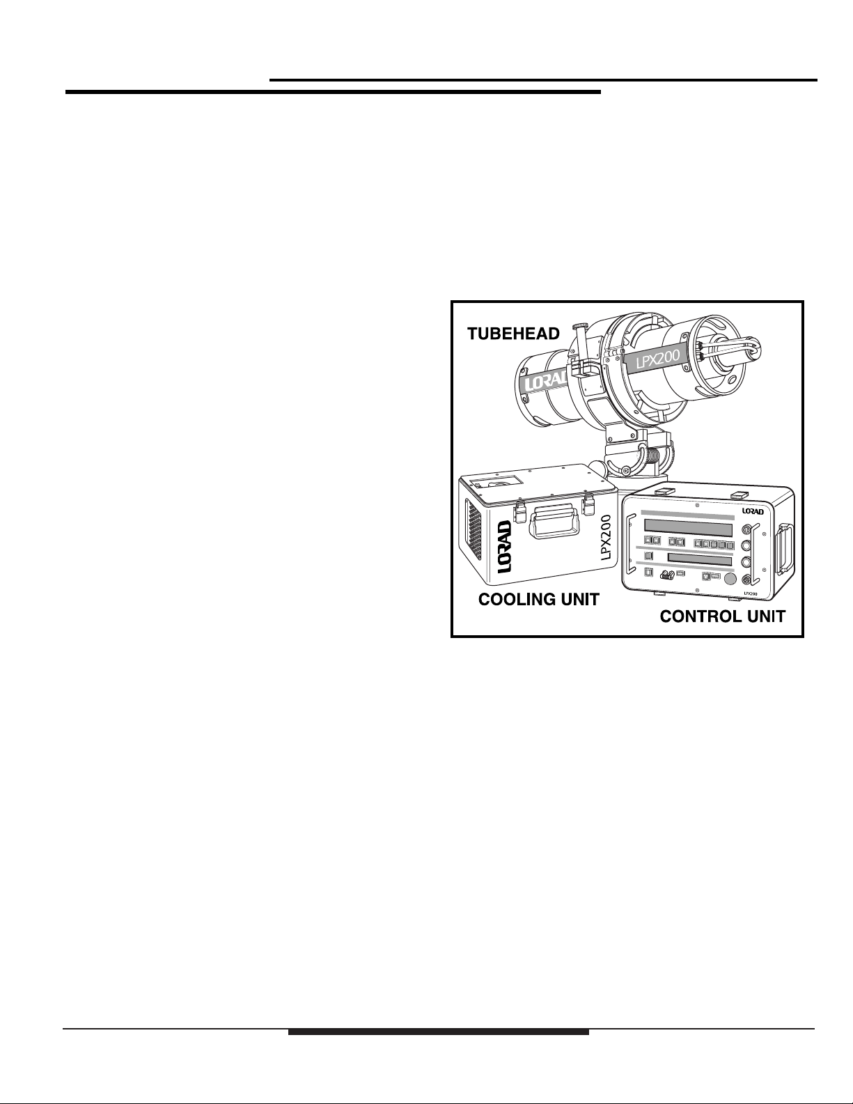
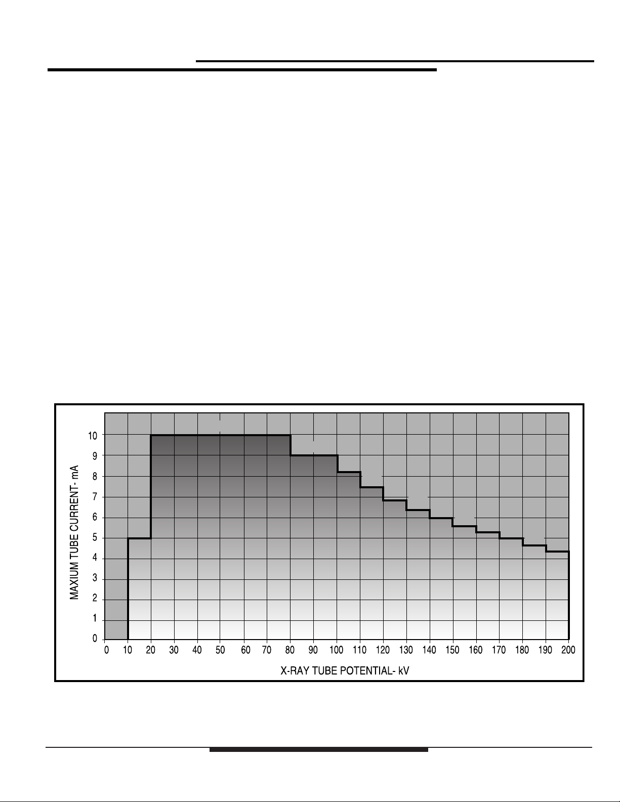
SYSTEM OVERVIEW
The LPX-200 can generate x-ray potential up to 200 kilovolts
(kV) and tube current up to 10 milliamperes (mA). The
maximum allowable dissipation is 900 watts. Maximum tube
current is limited automatically by the Control Unit to 10mA,
or to a value that does not cause dissipation greater than 900
watts at a set kV level.
The system offers a 100% duty cycle and consists of the
following assemblies:
◆ the Control Unit
◆ the Tube Head
◆ the Cooling Unit, (liquid cooled units only)
◆ the Electric Cooling Fan (air cooled units only)
Figure 1-1:
The LPX-200 X-ray System
These assemblies are described in detail next.
Chapter 1: Introduction & General Inf ormation
1-1
Page 10

LPX-200
Industrial Imaging System
The Control Unit
The radiographer uses the Control Unit to set the radiographic
exposure parameters, and to activate/deactivate x-ray
emissions from the Tubehead. One hundred feet of cable is
supplied with the system, which enables the Control Unit an
operator to maintain a safe distance from the x-ray Tubehead
during use.
The digital-based, microprocessor-regulated Control Unit
houses all the system pushbutton operating controls, an
exposure factor LCD Screen (for display of exposure factors),
a Message LCD Screen (for display of operating mode and
system messages), and the circuitry required to provide power
to the Tubehead and Cooling Unit.
The Control Unit is enclosed in a metal container with a
removable cover. A collapsible handle is attached to the cover
to provide a means of transporting the Control Unit.
The T ubehead
The Tubehead is a cylindrical aluminum shell assembly
housing the x-ray tube, the high voltage power supply, and the
filament supply. It is insulated with sulfur hexafluoride gas,
pressurized to 50 psi @70°F. Power to operate the x-ray tube
is supplied through a shielded cable that connects the
Tubehead to the Control Unit. The x-ray tube is end
grounded, with an exposed anode which contains a beryllium
window approximately 2 inches from the anode end. Built in
carrying handles are at each end of the Tubehead.
The Cooling Unit
(liquid-cooled units only)
The Cooling Unit dissipates heat generated at the anode of the
x-ray tube. Liquid coolant from a self-contained reservoir is
pumped through one side of a twin hose assembly, into the
Tubehead. In the Tubehead, coolant flows through a cooling
manifold, into the anode, and then back to the Cooling Unit
through the second half of the twin hose assembly.
Once in the Cooling Unit, coolant passes through a flow
switch that is electrically interlocked with the Control Unit,
and then through a filter to screen out contaminants. From the
filter, coolant flows through a forced air radiator, where
conducted heat is dissipated, and then back into the reservoir.
An electric motor-driven fan and pump assembly circulates
coolant and creates airflow through the radiator. Power is
supplied via an interconnecting cable from the Control Unit.
When properly connected to the system, the Cooling Unit is
automatically activated by a switching circuit within the
Control Unit.
There are two Tubehead models available:
◆ Liquid-cooled
◆ Air-cooled
The liquid-cooled Tubehead uses a separate Cooling Unit to
dissipate anode heat. These models have a length of twin hose
attaching the Tubehead to the Cooling Unit. Air-cooled
models have an electric cooling fan mounted at the anode end
of the Tubehead. The fan is powered by an interconnecting
cable from the Control Unit.
1-2
Chapter 1: Introduction & General Inf ormation
Page 11
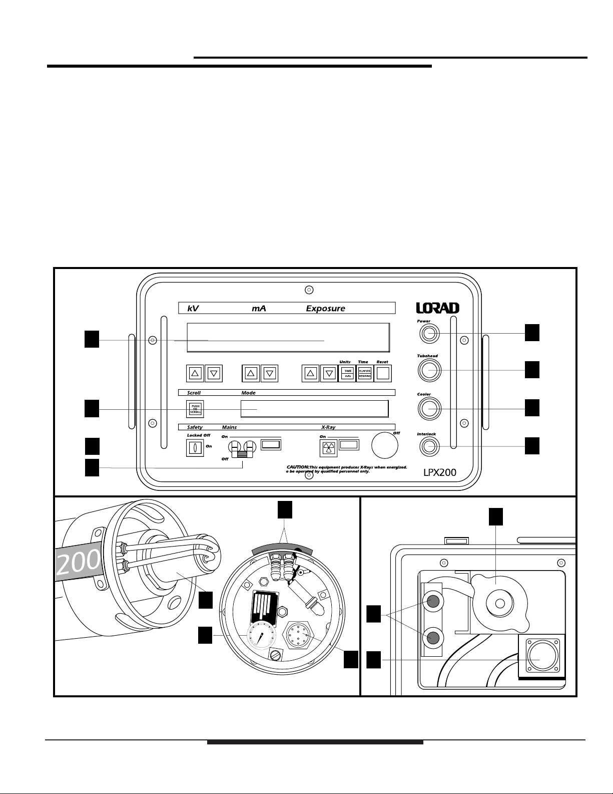
Legend - LPX-200 X-ray System
Use the following legend as a reference for parts
idnetification.
LPX-200
Industrial Imaging System
1. Exposure Technique LCD Display
2. Message LCD Display
3. Power Connector
4. Tubehead Connector
5. Cooler Connector
6. Interlock Connector
7. Mains On/Off Switch
CONTROL
UNIT
1
2
8
8. Lockout Keyswitch
9. Tubehead Anode
10. Tubehead Coolant Hose Fittings
11. Tubehead Gas Pressure Gauge
12. Tubehead Cable Connector
13. Cooling Unit Reservoir Cap
14. Cooling Unit Coolant Hose Fittings
15. Cooling Unit Cable Connector
3
4
5
6
7
TUBEHEAD
ASSEMBLY
10
9
11
Chapter 1: Introduction & General Inf ormation
COOLING
14
12
15
UNIT
13
Figure 1-2:
Legend - LPX-200
1-3
Page 12

LPX-200
Industrial Imaging System
MANUAL OUTLINE
This manual provides qualified radiographers and technicians
with a means to logically inspect, operate, and maintain the
LORAD LPX-200 Portable X-ray Unit. The following
paragraphs describe the arrangement of this manual and the
information contained in each section.
Chapter 1:
Introduction & General Information
This section provides general information about the LPX-200.
Included in this section is a safety summary.
Chapter 2:
Preparation For Use and Shipment
In this chapter, the user is provided instructions for unpacking
and reshipment, along with equipment checklists, and the
basic specifications of for assembly. Also included in
Chapter 2 are the locations of warning labels and I.D. tags.
Chapter 4:
LPX-200 X-ray Controls & Indicators
Chapter 4 details the controls and indicators on the LPX-200
Control Unit. Refer to this chapter during use for operational
details.
Chapter 5:
LPX-200 X-ray System Operation
The warm up and operating instructions for the LPX-200
X-ray Unit are detailed in Chapter 5. Included are
descriptions of error messages.
Section 6:
Routine Upkeep and Care
This chapter covers preventive maintenance and care
schedules for each assembly of the system. Included are
procedures for pressurizing and refilling the Tubehead,
cleaning the apparatus, and various general care practices.
Chapter 3:
Installing the LPX-200
This chapter provides instructions on making the
interconnections for both liquid cooled and air cooled units.
Also includes is a description of possible external interlock
connections.
1-4
Chapter 1: Introduction & General Inf ormation
Page 13
LPX-200
Industrial Imaging System
SAFETY SUMMARY
When properly installed, maintained, and operated, X-ray
equipment can be used effectively and safely. If any
component of this unit is incorrectly installed, and/or operated
by unqualified personnel, or if the maintenance schedule is
neglected, it is a potentially dangerous apparatus.
Before operating or performing any maintenance on the
LPX-200, the user MUST have a thorough understanding of
x-ray machinery, x-ray generation, x-ray potential, and x-ray
control. The user MUST understand all hazards associated
with x-ray generation.
Read this “Safety Summary” completely, and thoroughly
understand its contents. Read all of the safety warnings,
cautions, and notes throughout this manual prior to
commencing any operating or maintenance procedures.
All operators and technicians MUST adhere to the following
safety practices:
◆ Read and understand the x-ray protection warning
published at the front of this manual.
Use the following summary as a checklist to assure
comprehension of the safety indicators.
NOTE:
An essential operating procedure, condition, or
statement, which must be observed to ensure proper
understanding and operation of the system.
! CAUTION !
An operating or maintenance procedure,
practice, condition, or statement, which, if
not strictly observed, could result in
damage to, or destruction of equipment.
! WARNING !
An operating or maintenance
procedure, practice, condition, or
statement, which, if not strictly
observed, could result in injury to or
death of personnel.
◆ Read this manual in its entirety.
◆ Understand and all procedures completely before
operating the unit.
◆ Read thoroughly and understand completely all
NOTE, CAUTION, and WARNING statements
before beginning operation or maintenance
procedures.
Chapter 1: Introduction & General Inf ormation
1-5
Page 14

LPX-200
Industrial Imaging System
Radiation Hazard
This equipment generates X-radiation at levels that can be
lethal. This unit must only be operated by personnel that are
certified and experienced in industrial x-ray generation. All
operators must also understand the characteristics of radiation
and the associated dangers of exposure to primary, secondary,
and residual sources of radiation.
Lethal V oltages
High power radiation sources depend upon the generation of
extremely high, yet well-protected voltages. Under no
circumstances should the operator access the interior of the
Tubehead. Also, under no circumstances should the operator
access the interior of the Control Unit or the Cooling Unit
except for the procedures outlined in Section 5 of this manual.
Badges
All personnel who work around X-ray equipment must wear a
functional exposure dosage indicator.
Operation
Equipment must be operated at correct source voltage and
frequency, and must never be left running unattended. The
gas pressure in the Tubehead must be checked to ensure it is
within allowable limits before operating the unit. Never
operate this apparatus if output voltage/current is unstable.
Cooling Unit Operation
Regularly check the coolant solution in the Cooling Unit to
ensure:
◆ the coolant level is within specification
◆ the pump circulates the coolant properly
◆ the fittings, hoses, and coolant reservoir does not leak
Always allow the Cooling Unit, or the fan on air-cooled units,
to run approximately 5 minutes after completion of x-ray
generation.
Radiation Protection
X-ray equipment must be operated within properly designated
protective barriers. Otherwise, personnel must not approach
closer than 100 feet from the Tubehead, and in no cases cross
the direct path of the primary beam.
Radiation Monitoring
After installation, re-installation, transporting, performing
maintenance, and during all radiographic operations not
within a radiation enclosure, a radiation survey should be
performed.
Warm-Up Procedures
Explicit procedures are outlined for “running-up” high voltage
with new equipment, equipment with a new tube, equipment
that has been inactive for a period of time, and for daily use.
These procedures must be strictly followed at all times.
Care in Handling
Extreme care must be taken when handling this x-ray
apparatus. Exercise caution when packing, unpacking,
shipping, and while performing maintenance. Remember, the
X-ray tube is durable but breakable: be sure to store and ship
it in the upright position.
1-6
Chapter 1: Introduction & General Inf ormation
Page 15

Chapter 2:
Preparation for Use and Shipment
LPX-200
Industrial Imaging System
UNPACKING INSTRUCTIONS
The LPX-200 X-ray Unit is shipped in a single wooden
container. To gain access to the unit, perform the following:
◆ Remove the top cover from the crate.
◆ Carefully lift each component from the container.
◆ Perform a thorough visual inspection on each
component.
If damage to any component has occurred, immediately
contact the carrier. Keep all damaged containers until the
carrier completes an inspection by the carrier. If it is
necessary to re-package and ship the unit, follow the
instructions outlined under “Reshipment Guidelines”.
Reshipment Guidelines
In the event that the LPX-200 X-ray Unit must be transported
or shipped, use the original wooden container and packaging
material whenever possible. If the original shipping material
is not available, comply with the following re-packing
guidelines.
4. Pack the Control Unit in a container rated for 60 lbs.
Surround the Control Unit with a MINIMUM of 2"
of shock absorbent packing material (sheet or loose
type), including the top and bottom.
5. Pack the Cooling Unit in the same manner as the
Control Unit.
! WARNING !
The coolant solution is a flammable
substance and must be drained from
the Cooling Unit’s reservoir before it
can be shipped.
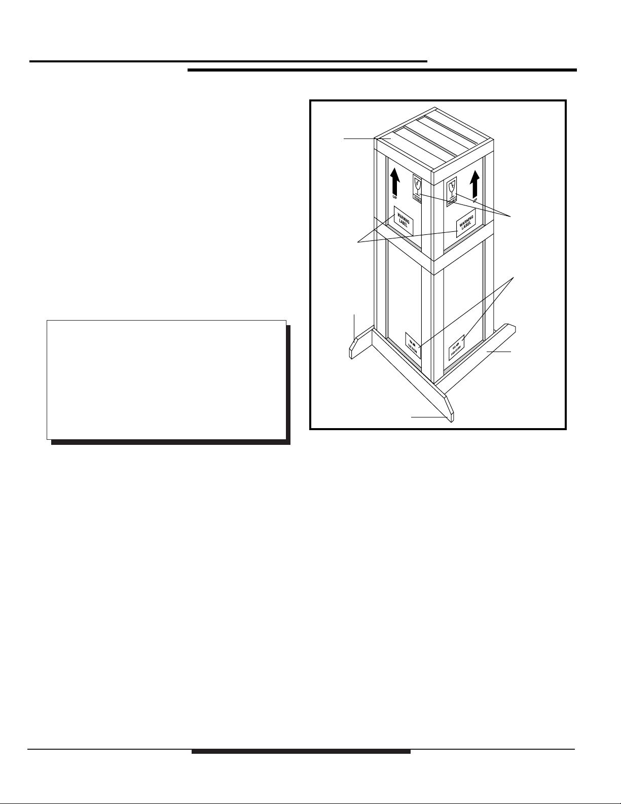
1. Construct a wooden shipping carton for the
Tubehead Assembly similar to the one in Figure 2-1.
Build the carton so that the top can be completely
removed to facilitate packing and unpacking.
2. Cushion the Tubehead with 3" of shock absorbent,
foam type, packing material (MINIMUM). This
material MUST surround the assembly on all sides,
including above and below the Tubehead.
3. Affix supporting legs to the bottom of the carton.
Make sure the legs extend between 7 and 10 inches
from the edges as shown in Figure 2-1.
Chapter 2: Preparation for Use and Shipment
2-1
Page 16
LPX-200
Industrial Imaging System
Transporting the Unit
When transporting by commercial carrier (i.e., truck, rail,
etc.), select the shipping method and carrier on the basis of
safe shipment, especially when shipping the fragile Tubehead
Assembly. Distinctly mark the Tubehead carton on all sides
with labeling which provides the carrier the following
information:
◆ Contents contains fragile glass instrumentation
◆ Container is to be shipped in the upright position
only
Customarily, the Tubehead is shipped via air, generally
avoiding ground transportation if possible. When shipping via
air, affix an additional label to the carton stating the following:
“Sulfur hexafluoride, non-flammable gas is
present in limited quantities in one or more
packages of this shipment. This is to certify that
the above mentioned materials are properly
classified, described, packaged, marked, and
labeled, and are in proper condition for
transportation according to the applicable
regulations of the U.S. Department of
Transportation.”
Removeable
Top
Fragile
Instrument
Label
Warning
Label
SF6 Label
Support
Leg
Support
Leg
Support
Leg
Figure 2-1:
T ubehead Shipping Container
2-2
Chapter 2: Preparation for Use and Shipment
Page 17

LPX-200
Industrial Imaging System
EQUIPMENT CHECKLISTS
The following checklists outline the standard and optional
equipment of the LPX-200 X-ray Unit. After unpacking the
unit, and completing a thorough visual inspection, compare
each item with this list to assure completeness.
Note that several Tubehead models are available. Verify that
the Tubehead shipped with your unit matches the model that
was originally ordered.
Checklist - Tubehead
❏ Assembly, Tubehead* ______ 3-000-3071
Air Cooled Unit; 40° x 60° cone
1.5mm Focal Spot
1mm Beryllium Window
❏ Assembly, Tubehead _______ 3-000-3072
Liquid Cooled; 40° x 60° cone
1.5mm Focal Spot
1mm Beryllium Window
❏ Assembly, Tubehead _______ 3-000-3073
Liquid Cooled; 360° Panoramic
0.4mm x 4.0mm Focal Spot
0.4 Fe/Ni/Co Window Tube
* All Air Cooled Units are equipped with Fan Power
Cable (p/n: 1-040A-0355). The liquid Cooling Unit
is not equipped with this cable.
Checklist - Standard Equipment
❏ Control Unit, Digital (1) ____ 3-000-3074
❏ Cooling Unit Assembly (1) __ 3-000A-0737
(Liquid Cooled Units Only)
❏ Power Cable Assembly (1) __ 1-040A-0825
(3 Pin Connector, 25ft.)
❏ Power Cable Assembly (1) __ 1-040A-0831
(3 Pin Connector, 100ft)
❏ Control Cable Assembly (1) _ 1-040A-0824
(14 Pin Connector, 100ft.)
❏ Cooler Power Cable (1)_____ 1-040A-0823
(Liquid Cooled Units Only, 8 Pin
Connector, 50ft.)
❏ Power Cable, Fan (1)_______ 1-040A-0355
(Air Cooled Units Only, 100ft.)
❏ Interlock Jumper (1) _______ 3-000-3075
(Jumper)
❏ Safety Switch Key (2) ______ 2-230-6201
❏ Interlock Connector (1) _____ 1-600-3218
(Mating Connector)
Checklist - Optional Equipment
❏ X-Ray Tubehead Stand _____ 3-000A-0754
❏ Kit, Tubehead Re-charge____ 9-200A-0102
❏ Laser Pointer _____________ 3-000-0792
❏ Laser Pointer Adapter ______ 3-100-0175
Chapter 2: Preparation for Use and Shipment
2-3
Page 18
LPX-200
eeeeeeeeeeeeeeeeee
eeeeeeeeeeeeeeeeee
eeeeeeeeeeeeeeeeee
eeeeeeeeeeeeeeeeee
eeeeeeeeeeeeeeeeee
eeeeeeeeeeeeeeeeee
eeeeeeeeeeeeeeeeee
eeeeeeeeeeeeeeeeee
eeeeeeeeeeeee
eeeeeeeeeeeee
eeeeeeeeeeeee
eeeeeeeeeeeee
eeeeeeeeeeeee
eeeeeeeeeeeee
eeeeeeeeeeeee
eeeeeeeeeeeee
eeeeeeeeeeeee
eeeeeeeeeeeee
Industrial Imaging System
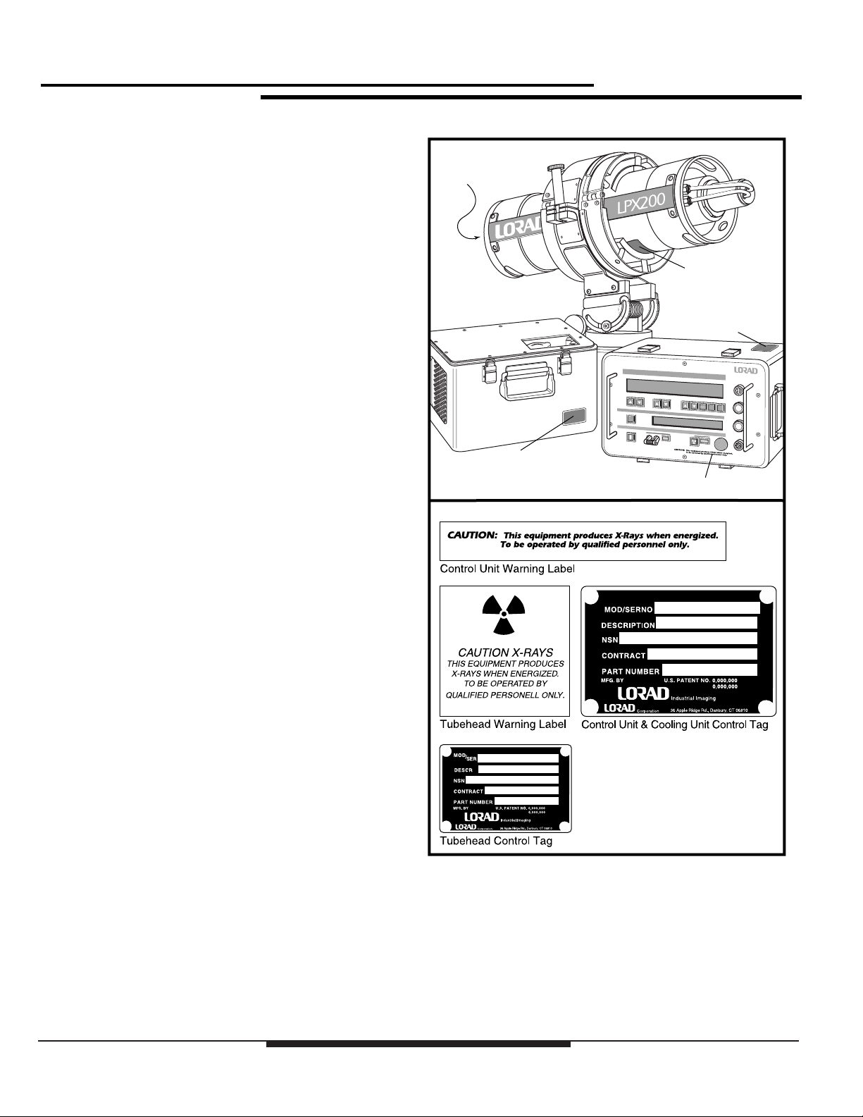
WARNINGS LABELS &
CONTROL NUMBERS
Each assembly of the LPX-200 X-ray System is equipped
with an I.D. tag (Control Tag) providing the serial number,
description, and part number. This data is used for
identification, if warranty or service information is needed,
and will be requested when contacting LORAD regarding the
apparatus.
Control Tag
Warning Label
Attached to the Control Unit and Tubehead are warning labels.
Figure 2-2 illustrates the location of the I.D. tags and warning
labels for each assembly of the LPX-200.
Control Tag
Control Tag
Warning Label
2-4
Figure 2-2:
Location of Warning Labels and Control Tags
Chapter 2: Preparation for Use and Shipment
Page 19
SPECIFICATIONS
The following tables illustrate the physical, operational, and
environmental specifications for each component of the
LPX-200 System. Conformance with these specifications
ensures maximum system performance, and reduces the
chances of mechanical breakdown and personnel hazard.
Specifications - General System
LPX-200
Industrial Imaging System
The following outlines the general operating and
environmental limits of the LPX-200 System.
❏ Line Voltage * ____________ 100 to 130 VAC - 50/60 Hz, 20
amps (maximum); or 200 to 250
VAC - 50/60 Hz, 10 amps
(maximum)
❏ Operating Potential ________ 10kV to 200kV @ 0.1 to 10.0
mA, 900 Watts maximum
❏ Duty Cycle ______________ 100%
10.0
5.0
❏ Operating Temperature Range -30°F to 120°F (Ambient)
-34°C to 49°C (Ambient)
❏ Humidity ________________ 0 to 100% relative humidity
❏ Stabilization______________ kV and mA remain within 1% of
set levels. Line voltage varied
from 100-130/200-250 VAC.
❏ Storage Temperature Range _ -65°F to 160°F (-54°C to 71°C)
* Line voltage selection is automatic. The system is
operable from either line voltage range without any
switch or jumper configuration.
9.0
8.2
7.5
6.9
6.4
6.0
5.6
5.3
5.0
4.7
4.5
Chapter 2: Preparation for Use and Shipment
Figure 2-3:
LPX-200 Maximum T ube Current
2-5
Page 20

LPX-200
Industrial Imaging System
Specifications - General Tubehead
The following outlines the general operating specifications of
the Tubehead Assembly.
❏ Physical Specifications _____ Water Cooled: 8.5" dia. x 26.5"
length - 32lbs (approx); Air
Cooled: 8.5" dia. x 29" length 36 lbs (approx)
❏ Anode Cooling System _____ Recirculating Liquid Cooling unit
or Fan Forced Air
❏ Radiation Output __________ 20R/minute @200kV, 4.5mA @
50cm through 0.5 in. of
Aluminum
❏ Leakage Radiation_________ 0.8 R / hr
❏ Tube Pressure Sense _______ Monitors pressure of the SF6 gas
within the Tubehead. Shuts unit
down if pressure falls below 25
psi.
❏ Anode Thermal Sense ______ Monitors temperature of the X-ray
Tube Anode. Shuts down unit if
Anode temperature rises above
220°F.
DIRECTIONAL TUBE HEADDIRECTIONAL TUBE HEAD
60˚
40˚
PANORAMIC (360˚)TUBE HEAD
❏ Pressure Relief Valve_______ Automatically releases SF6 gas
from Tubehead if pressure rises
between 75 - 80 psi.
❏ Pressure Gauge ___________ Displays SF6 gas pressure within
Tubehead. Used in conjunction
with Temperature Compensation
chart to visually inspect Tubehead
pressure.
Specifications - Optional Tubehead
The information that follows furnishes the specifications for
several available Tubehead assemblies. Figure 2-4 illustrates
the direction of the X-ray beam for both the 40° x 60° cone
and the 360° panoramic models.
❏ Tubehead 40° x 60° Cone ___ Air or liquid cooled models;
1.5mm Focal spots; 1mm
beryllium window
❏ Tubehead 360° Panoramic __ Liquid cooled, 0.4mm x 4.0mm
focal spot, 0.4 Fe/Ni/Co window
only
44˚
Figure 2-4:
X-ray Beam Path
2-6
Chapter 2: Preparation for Use and Shipment
Page 21

LPX-200
Industrial Imaging System
Specifications - Control Unit
Below are the physical and operating specifications of the
Control Unit. Included are the physical dimensions, and the
operating indicators and controls. The controls are explained
in detail in Section 4 of this manual.
❏ kV Control_______________ Pushbutton switches set kV level
between 0kV to 200kV in 1kV
increments
❏ kV Indicator _____________ LCD Readout on upper display
❏ mA Control ______________ Pushbutton switches set mA level
between 0 and maximum 10.0 mA
in 0.1 mA increments (Control
Unit automatically limits the mA
so that 900 watt maximum is not
exceeded)
❏ mA Indicator _____________ LCD Readout on upper display
❏ X-Ray ON Switch _________ Pushbutton switch with radiation
symbol. Activates x-ray
generation
❏ X-Ray OFF Switch ________ Red mushroom type switch
terminates x-ray generation. May
be depressed anytime while x-rays
are being generated.
Specifications - Cooling Unit
Below are the operating and physical specifications of the
Cooling Unit.
❏ Dimensions ______________ 12" H x 15" W x 14" L
❏ Weight __________________ 55 lbs (approximate)
❏ Coolant Solution __________ 14 parts methyl alcohol, 7 parts
distilled water, 1 part soluble oil
(TEXACO Soluble “D” or
MOBIL S-122 Soluble)
❏ Coolant Flow_____________ 0.5 gallons per minute @ 50 foot
head.
❏ Cooling Unit Connections___ Self sealing quick disconnects.
❏ Key Lock Safety Switch ____ LOCKED OFF position prevents
x-ray generation; ON position
enables X-RAY ON switch
❏ Exposure Timer___________ LCD readout on upper display
❏ Weight __________________ 35 lbs. (approximate)
Dimensions _________________ 12" W x 18" L x 12" H
❏ Power ON Indicator _______ Green LED array on front panel
❏ X-Ray ON Indicator _______ Red LED array on front panel
❏ Interlock Connector________ Pins A and B used for enclosure
door switches which must be
closed to enable the X-RAY ON
switch. Pins C and D used for
external warning devices, pins E
and F used with optional prewarn/
warning systems.
Chapter 2: Preparation for Use and Shipment
2-7
Page 22

LPX-200
Industrial Imaging System
THIS PAGE IS INTENTIONALLY BLANK
2-8
Chapter 2: Preparation for Use and Shipment
Page 23

Chapter 3:
Installing the LPX-200 X-ray System
PRE-OPERATIONAL
CHECKS & INSPECTION
The following paragraphs outline the steps to properly check
and inspect the LPX-200 X-ray unit. Perform these
procedures before setting up the system to ensure integrity.
Check - Tubehead Gas Pressure
LPX-200
Industrial Imaging System
Check - Cooling Unit
This check verifies the integrity of the Cooling Unit (liquid
cooled tubeheads only).
1. Inspect the twin hose assembly and hose connections
for damage. The connector couplings must be firmly
attached to the hose, and the hose must be free of
punctures, frays, or dry rot.
This check verifies that the gas pressure inside the Tubehead
assembly is within limits. Note that Tubehead gas pressure
normally varies 1 psi for every 7°F increase or decrease in
ambient air temperature.
! CAUTION !
DO NOT operate this unit if Tubehead
Pressure is below 50 psi at 70°F or damage
to the Tubehead may occur.
1. Check the Tubehead gas pressure gauge and verify
that the gas pressure is within acceptable limits for
the ambient temperature (see Figure 6-2).
2. If the gauge indicates Tubehead gas pressure below
the acceptable limit, but greater than 5 psi, perform
the procedures for “Pressurizing the Tubehead” (refer
to Section 5).
3. If Tubehead gas pressure is below 5 psi at 70°F,
purge the Tubehead of all remaining gas, then
perform the procedures for “Refilling the Tubehead”
(see Section 5).
2. Remove the Radiator cap on the Cooling Unit and
check that the coolant level is within 1/2" from the
top of the reservoir. Add coolant solution at this time
if necessary (refer to Section Five).
Check - Control Unit
This check verifies the intergrity of the Control Unit.
1. Remove the top cover from the Control Unit and
perform a thorough visual inspection for damage.
2. Check the four connectors along the right side of the
front panel for foreign material and signs of
corrosion.
3. Inspect the front panel controls for missing or
broken switches and displays.
Chapter 3: Installing the LPX-200 X-ray System
3-1
Page 24

LPX-200
Industrial Imaging System
SYSTEM SET UP PROCEDURES
The procedures below describe the set up procedures for both
LPX-200 configurations; liquid-cooled units, and air-cooled
units. Use Figure 3-1 (liquid-cooled), or Figure 3-2 (aircooled) as a reference while making the necessary system
connections.
System Interconnections - Liquid Cooled
The following details the connections for setting up a liquid
cooled LPX-200 X-ray System.
! WARNING !
All cables MUST be connected to their
appropriate connectors on the
Control Unit, Cooling Unit, and
Tubehead before applying power to
the system.
1. Connect the twin hose assembly between the
Tubehead and the Cooling Unit:
◆ Attach the two angled couplings to the fittings on the
back of the Tubehead.
◆ Attached the couplings on the opposite end to the
female fittings on the Cooling Unit.
5. Make the External Interlock connection:
◆ If available, connect the Interlock cable to the
connector labeled “Interlock” on the Control Unit
(see External Interlock instructions later in this
section).
◆ Connect the “jumper” (supplied) to the connector
labeled “Interlock” on the Control Unit for units that
do not employ an external interlock system.
COOLER
Cable
8 pin connector
UNIT
Twin Hose
NOTE:
There is no designated left or right side to the twin
hose assembly. If each coupling is properly seated,
coolant flow through the Tubehead will be achieved.
2. Install the Cooling Unit power cable:
◆ Connect the male end of the power cable to the
connector labeled “Cooler” on the Control Unit.
◆ Connect the female end of the power cable to the
connector on the Cooling Unit.
3. Install the Tubehead Control cable:
◆ Connect the male end of the Control cable to the
connector labeled “Tubehead” on the Control Unit.
◆ Connect the female end of the Control cable to the
connector on the Tubehead base plate.
4. Install the line power cable:
◆ Connect the female end of the line power cable to the
connector labeled “Power” on the Control Unit.
◆ Connect the “plug” end of the line power cable to the
AC voltage source (see Connecting to Power
instructions later in this section).
TUBEHEAD
Line Power Cable
to AC Source
CONTROL
UNIT
LPX-200 Set Up (Liquid Cooled)
Cable
10 pin connector
Interlock Connection
or Jumper
Figure 3-1:
3-2
Chapter 3: Installing the LPX-200 X-ray System
Page 25

System Interconnections - Air Cooled
The following details the connections for setting up a liquid
cooled LPX-200 X-ray System.
! WARNING !
All cables MUST be connected to their
appropriate connectors on the
Control Unit, Cooling Unit, and
Tubehead before applying power to
the system.
1. Install the Cooling Fan power cable:
◆ Connect the male end of the power cable to the
connector labeled “Cooler” on the Control Unit.
◆ Connect the female end of the power cable to the
connector on the Tubehead base plate.
2. Install the Tubehead Control cable:
◆ Connect the male end of the Control cable to the
connector labeled “Tubehead” on the Control Unit.
◆ Connect the female end of the Control cable to the
connector on the Tubehead base plate.
3. Install the line power cable:
◆ Connect the female end of the line power cable to the
connector labeled “Power” on the Control Unit.
◆ Connect the “plug” end of the line power cable to the
AC voltage source (see Connecting to Power
instructions later in this section).
Line Power Cable
to AC Source
CONTROL
UNIT
TUBEHEAD
LPX-200
Industrial Imaging System
Cable
8 pin connector
Cable
10 pin connector
Figure 3-2:
LPX-200 Set Up (Air Cooled)
4. Make the External Interlock connection:
◆ If available, connect the Interlock cable to the
connector labeled “Interlock” on the Control Unit
(see External Interlock instructions later in this
section).
◆ Connect the “jumper” (supplied) to the connector
labeled “Interlock” on the Control Unit for units that
do not employ an external interlock system.
Chapter 3: Installing the LPX-200 X-ray System
3-3
Page 26

LPX-200
Industrial Imaging System
Connecting to Po wer
Note that the AC voltage source MUST be rated as either:
◆ 120 VAC, 20 amps, 50/60 Hz
◆ 230 VAC, 10 amps, 50/60Hz
Line voltage selection is automatic. For 220V input
application, remove the male plug on the supplied power cord
and replace it with one that fits the local AC receptacle, or an
adapter cable can be locally manufactured. See Figure 3-3 for
the correct plug termination.
EXTERNAL
INTERLOCK CONNECTIONS
The INTERLOCK connector on the front panel of the Control
Unit enables interconnection of x-ray enclosure doors and/or
external warning devices with the internal safety interlock
circuitry of the system. Figure 3-4 illustrates the two circuits
provided for this purpose.
Pins “A” and “B” are used to connect enclosure door switches.
When pins A and B are properly connected, x-ray generation
is possible only when the enclosure doors housing the
Tubehead are shut. Note that pins “A” and “B” of the
INTERLOCK connector must form a closed circuit to operate
the X-ray unit. If no external switch interlocks are
incorporated, a jumper (provided) must be installed across
pins “A” and “B” to form this closed circuit.
Pins “C” and “D” provide a switch closure to operate warning
devices such as lights, sirens, or other types of external
warning signals. These signals warn all personnel that x-rays
are being generated.
(Earth Ground)
GREEN
A
B
C
INTERLOCKINTERLOCKINTERLOCK
D
A
B
C
D
External Relay
BLACK
WHITE
Figure 3-3:
220 V olt Plug Termination
F
E
F
E
External Interlocks
Indicator Lamps
30VDC
120/240VAC
3 AMPS (max)
Indicator Lamps
Pins E and F are for use with optional LORAD pre-warning/
warning devices.
! WARNING !
Voltage is present at pins “A” and “B”
of the INTERLOCK when the unit is
powered up. Ensure power is OFF
before making any external
connections or while installing the
jumper.
3-4
Chapter 3: Installing the LPX-200 X-ray System
A
B
C
A
B
C
INTERLOCK
D
F
E
D
F
E
30VDC
120/240VAC
3 AMPS (max)
Jumper
Figure 3-4:
External Interlock Connections
Page 27

Chapter 4:
LPX-200 X-ray Controls and Indicators
LPX-200
Industrial Imaging System
INTRODUCTION
The following paragraphs describe the controls and switches
on the control panel of the LPX-200 Control Unit. The
functions and use of these controls must be thoroughly
understood before operating the x-ray unit.
Overview - Control Unit
The Control Unit’s control panel is comprised of:
◆ 2 liquid crystal display (LCD) screens
◆ exposure parameter pushbutton control switches
◆ a Mains power circuit breaker
◆ LED indicators
Military type connectors, along the right side of the panel, are
used to connect the input power cord and the system’s
interconnecting control cables and hoses.
Legend - LPX-200 Control Unit
Use the following legend as a reference for parts
identification.
1. Exposure Technique LCD Display Screen
2. Message / Mode LCD Display Screen
3. Mains ON/OFF Circuit Breaker
4. Mains LED Indicator
5. Safety Key Lockout Switch
6. kV UP/DOWN Pushbuttons
7. mA UP/DOWN Pushbuttons
8. EXPOSURE (Time/mAs) UP/DO WN Pushb uttons
9. UNITS Select (Time/mAs) Pushb utton
10. TIME Counter Select Pushbutton
11. RESET Pushbutton
12. SCROLL Control
13. X-RAY ON Pushbutton
14. X-RAY OFF Pushbutton
7891011
1
6
12
354 14132
Chapter 4: LPX-200 X-ra y Controls & Indicators
Figure 4-1:
Legend - LPX-200 Control Panel
4-1
Page 28

LPX-200
Industrial Imaging System
THE LIQUID
CRYSTAL DISPLAY SCREENS
The LPX-200 Control Unit incorporates two LCD Display
screens:
◆ The Exposure Technique LCD
◆ The Message / Mode LCD
The following paragraphs describe both LCD screens, and the
information they provide the user.
The Exposure Technique LCD Display Screen
The Exposure Technique LCD (large top screen) displays two
rows of exposure parameters:
◆ the set techniques (top row)
◆ the operating levels (bottom row)
The top row shows the set exposure kV (left side), the mA
(center), and the exposure duration (right side). The exposure
duration displays in minutes and seconds or in mAs,
depending on the selected TIME mode.
The bottom row shows the actual operating levels of the
system during x-ray emission. The operating kV level
displays directly below the set kV level, the actual tube current
(mA) displays directly below the set mA, and the actual time
(or mAs) remaining/elapsed displays directly below the set
exposure duration.
Figure 4-2:
Samples: Exposure Te chnique LCD Display
4-2
Chapter 4: LPX-200 X-ra y Controls & Indicators
Page 29

The Message / Mode LCD Display Screen
The Message / Mode LCD (small bottom screen) displays:
◆ operating mode
◆ user prompts
◆ error messages
The upper left side of the screen indicates the system
operational mode (OPERATE or AUTOWARM), and the
lower left side show the either the type of automatic warm-up
has been selected (i.e., > 30 DAYS), or if an error condition
has been encountered (FAULT).
The right hand side of the screen indicates the following:
◆ the current operating status
◆ the description of the detected fault
Figure 4-3 shows several examples of the information
provided on the Message / Mode screen.
LPX-200
Industrial Imaging System
Samples: Message / Mode LCD Display Screen
Chapter 4: LPX-200 X-ra y Controls & Indicators
Figure 4-3:
4-3
Page 30

LPX-200
Industrial Imaging System
FRONT PANEL
CONTROLS AND INDICATORS
The paragraphs that follow describe each of the controls and
indicators on the front panel of the Control Unit. Refer to
Figure 4-1 for the location of each control and indicator.
The MAINS Switch
The MAINS switch is a two position circuit
breaker that applies power to the Control Unit.
Switching the MAINS breaker ON applies line
power to the Control Unit after a 2 second delay
(approximate). During this delay, the input power detection
circuitry determines the line voltage (100VAC or 200VAC),
and selects the proper line circuitry.
Switching the MAINS breaker OFF immediately disconnects
the system from line power. The MAINS breaker will trip
automatically during over-current conditions, thus protecting
the internal electronics from damage.
The MAINS ON Indicator
The MAINS ON indicator is a light emitting diode
(LED) array located next to the MAINS Switch.
This LED glows green when line power is applied to
the system.
The kV SET Controls
Two pushbuttons, below the kV readout,
comprise the kV SET Controls. Use these
buttons to increment or decrement the kV level
for the exposure. Pressing the kV UP button, identified by the
“up arrow” label, increments the set kV in 1kV steps (up to
200kV maximum). Pressing the kV DOWN button, identified
by the “down arrow” label, decrements the set kV in 1kV
steps (to 0kV minimum).
For rapid change, press and hold the kV UP or DOWN button;
for slow change, press and release the buttons. These switches
are active:
◆ upon initial system power up
◆ during an exposure (OPERATE)
◆ prior to an exposure (provided the Exposure Counter
has been reset)
The mA SET Controls
Two pushbuttons, below the mA readout,
comprise the mA SET Controls. Use these
buttons to increment or decrement the mA
level for the exposure. Pressing the mA UP button, identified
by the “up arrow” label, increments the set mA in 0.1mA steps
(up to 10mA maximum). Pressing the mA DOWN button,
identified by the “down arrow” label, decrements the set mA
in 0.1mA steps (to 0.0mA minimum).
The SAFETY Switch
The 2-position SAFETY switch prevents
unauthorized use of the X-ray Unit. Before the
system can generate x-rays, the operator MUST
insert the key into the SAFETY switch, then rotate
it to the ON position. The SAFETY switch does not activate
x-ray generation; it only permits use of the x-ray apparatus.
Never approach the Tubehead when power is ON without first
placing the SAFETY switch to LOCKED OFF, then removing
the key. NEVER leave the key in the SAFETY switch unattended.
4-4
Chapter 4: LPX-200 X-ra y Controls & Indicators
For rapid change, press and hold the kV UP or DOWN button;
for slow change, press and release the buttons. These switches
are active upon:
◆ upon initial system power up
◆ during an exposure (OPERATE)
◆ prior to an exposure (provided the Exposure Counter
has been reset)
NOTE:
The microcomputer limits the maximum mA to
values which, at the set kV level, provide a
maximum of 900 watts to the tube.
Page 31

LPX-200
Industrial Imaging System
The EXPOSURE SET Controls
Two pushbuttons, below the Exposure readout,
comprise the EXPOSURE SET Controls. Use
these buttons to increment or decrement the
exposure time (Time Mode) or mAs (mAs Mode). Pressing
the EXPOSURE UP button, identified by the “up arrow” label,
increments the set exposure time (up to 99:59 maximum), or
the set mAs (up to 29995 maximum). Pressing the
EXPOSURE DOWN button, identified by the “down arrow”
label, decrements the set exposure time (to 00:00 minimum),
or the set mAs (to 00000mAs minimum).
For rapid change, press and hold the UP or DOWN button;
for slow change, press and release the buttons. These switches
are active:
◆ upon initial system power up
◆ in the OPERATE mode
◆ prior to an exposure (provided the Exposure Counter
has been reset)
The UNITS Control
The UNITS Control is a single pushbutton, next to
the EXPOSURE SET Controls, that changes the
mode that the system uses to determine the exposure
duration. Pressing the UNITS button will toggle the system
exposure determination mode between TIME and mAs.
Selecting TIME causes the x-ray system to terminate the
exposure after a pre-determined “time” has elapsed, regardless
of the set exposure factors (kV and mA). Selecting mAs
causes the x-ray system to terminate the exposure after a
achieving a set tube current / time product (mAs), and does
not require an operator time calculation.
The TIME Control
The TIME Control is a single pushbutton, next to the
UNITS Control, that switches the exposure clock
between ELAPSED mode (count up), and REMAINS
mode (count down). This control is active at all times when
power is ON.
ELAPSED mode sets the time or mAs in the lower Exposure
readout to zero, then increments during the exposure. When
the “elapsed” time or mAs matches the set time or mAs (upper
Exposure readout), the system terminates the exposure.
REMAINS mode sets the time or mAs in the lower Exposure
readout to the set time or mAs (upper Exposure readout), then
decrements during the exposure. When the “remains” time or
mAs reaches zero, the system automatically terminates the
exposure.
The RESET Control
The RESET control is a single pushbutton, next to the TIME
Control, that resets the exposure timer. Pressing the RESET
control causes the exposure duration (lower readout) to do one
of the following:
◆ Return to the set time or mAs (REMAINS mode)
◆ Return to zero (ELAPSED mode)
The RESET pushbutton is active only when:
◆ the system terminates the exposure upon reaching the
set duration
◆ the system terminates the exposure due to a fault
condition
◆ the user interrupts the exposure by pressing STOP
When the x-ray system is in the TIME mode, TIME SET will
appear next to the set exposure time (top row) in the Exposure
Factor LCD. When the x-ray system is in the mAs mode, mAs
will appear next to the set mAs (top row) in the Exposure
Factor LCD.
This switch is active upon:
◆ upon initial system power up
◆ upon system exposure termination
◆ upon exposure interuption
◆ after resetting the Exposure Counter
Chapter 4: LPX-200 X-ra y Controls & Indicators
4-5
Page 32

LPX-200
Industrial Imaging System
The SCROLL Control
The SCROLL Control is a single pushbutton, to the
left of the Message / Mode LCD, that switches the
system status between the available modes. Pressing
the SCROLL button switches the display in the Message /
Mode LCD between:
◆ OPERATE
◆ AUTOWARM > 30 DAYS
◆ AUTOWARM 7 - 30 DAYS
◆ AUTOWARM 16 HRS - 7 DAYS
◆ AUTOWARM 8 HRS - 16 HRS
◆ AUT OWARM 4 HRS - 8 HRS
Select the OPERATE mode to make radiographs after
completing the appropriate warm-up sequence (if required).
Select the appropriate AUTOWARM mode to “run up” to the
required kV level at a fixed rate when the equipment has not
been used for a period of time (see “Warm Up Sequence” in
Chapter 5).
The X-RAY ON Control
The X-RAY ON Control, identified by the radiation
symbol, starts x-ray generation, and turns on the X-
RAY INDICATOR. The X-RAY ON Control is
active only when all of the following conditions are
met:
The X-RAY OFF Control
The X-RAY OFF control is the red, mushroomtype pushbutton switch, near the bottom of the
control panel. Pressing this switch anytime during
an exposure causes:
◆ termination od x-ray production
◆ the exposure counter to stop
◆ the x-ray on LED to extinguish
The timer will continue to display the exposure time or mAs
(elapsed or remaining). To continue with the exposure, repress the X-RAY ON button. The exposure will continue from
the point that the OFF control was originally pressed. To start
a new exposure, press the RESET button, set new exposure
factors, then re-press the X-RAY ON button.
◆ power is applied to the system
◆ The keyswitch is turned ON
◆ all error / fault conditions have been corrected
The X-RAY Indicator
The X-RAY indicator, next to the X-RAY ON
control, is a light emitting diode (LED) that glows
red when x-rays are being generated.
4-6
Chapter 4: LPX-200 X-ra y Controls & Indicators
Page 33

Chapter 5:
LPX-200 X-ray System Operation
LPX-200
Industrial Imaging System
INTRODUCTION
This section provides, as an example, the sequence of
operation required for using the LPX-200 X-ray System for
making x-ray film exposures. ALWAYS keep in mind the
dangers inherent with generating x-radiation, and observe
ALL the relevant precautions and procedures regarding safe
operation, personnel exposure prevention, and exposure dose
monitoring.
Pre-Operational Safety Precautions
Before the x-ray tube is energized for either the warm-up
sequence, or for the exposure, the operator MUST understand
and observe the safety precautions detailed below.
The interconnects supplied with the system help protect the
user, and others in the immediate vicinity, from exposure by
providing a safe distance between the Tubehead and the
Control Unit. Refer to NCRP (National Council on Radiation
Protection) recommended practices for minimum distance
requirements.
! WARNING !
ALWAYS use the cables and hoses
provided with the unit to avoid
radiation hazards in un-shielded,
outdoor operating conditions.
The operator of this apparatus MUST ensure that all personnel
are clear of the hazardous X-ray area before generating
X-rays. Utilize flashing beacons and/or audible alarms during
exposures, which warn personnel of the radiation hazards.
! WARNING !
All personnel in the immediate
vicinity MUST wear personal
radiation monitoring devices. Post
radiation warning signs where
necessary.
The operator of this X-ray unit, or any person in the
immediate vicinity, may be subject to receiving some
exposure to X-radiation during the time that the X-ray unit is
generating X-rays. Since X-rays can cause harmful
effects to the human body, avoid unnecessary exposure.
! WARNING !
Keep all necessary exposure to an
absolute minimum and compatible
with practical requirements and
current safety regulations. An X-ray
survey meter, placed in the vicinity of
the Control Unit and operator, is
recommended.
! WARNING !
Connect all cables to their
appropriate connectors on the
Control Unit, Cooling Unit, and
Tubehead BEFORE applying power to
the system.
Chapter 5: LPX-200 X-r a y System Operation
5-1
Page 34

LPX-200
Industrial Imaging System
X-RA Y TUBE W ARM UP
The X-ray tube provided with the LPX-200 has been pre-aged
by the original manufacturer, and further tested and aged by
LORAD. It is necessary, however, to run the voltage up to the
required kV level at a fixed rate when the equipment has not
been used for a period of time.
The LPX-200 incorporates an AUTOWARM feature, which
permits the user to select and initiate one of five automatic
warm-up sequences. An AUTOWARM sequence is required
whenever the x-ray system:
◆ is to be operated above 100kV
◆ has not been operated at the required kV level for the
next exposure for 4 hours
◆ has a new tube with less than ten hours of operation
The AUTOWARM modes automatically set the run-up level to
200kV. However, it is only necessary to run the x-ray tube to
the kV level required for the next exposure. Run the
appropriate AUTOWARM sequence until the kV advances to
the next level higher than required for the exposure, then
terminate the sequence. Tubes having been previously
operated, but not run over 100kV for 30 days or longer, must
be treated as new tubes.
Note that for ALL AUTOWARM modes, detected tube
instability (as might occur with a new tube) causes the system
to automatically terminate x-ray generation. The Message /
Mode LCD will display an error (FAULT ARC RESTART),
which will require the user to re-activate x-ray generation.
The kV will then rise to a level 20kV below where the fault
occurred and operate for two minutes. After two minutes, the
kV advances to the next highest incremental kV level on the
selected warm-up schedule, and the AUTOWARM sequence
continues normally from that point.
The five AUTOWARM sequences are detailed next.
Autowarm Sequence : > 30 Days
The following procedure outlines the steps to “run-up” the kV
to the level required for the next exposure in cases where the
unit has not been operated for 30 days or more.
1. Prepare the x-ray system for the warm-up sequence:
❏ Turn the anode shield to completely block x-ray port.
❏ Close all interlock connections, or install the jumper
on the INTERLOCK connector.
❏ Place the MAINS circuit breaker ON.
! WARNING !
Although the window is blocked, do
not approach the Tubehead during
the warm up process. Observe all
applicable safety precautions and
survey the area to assure adequate
radiation limits.
2. Begin the AUTOWARM sequence:
❏ Select AUTOWARM : > 30 DAYS by pressing the
SCROLL button.
❏ Clear all unauthorized personnel from the area, and
activate all warning devices.
❏ Press the X-RAY ON button to begin the
AUTOWARM sequence.
! WARNING !
The system will now generate x-rays.
Observe ALL safety precautions.
Upon activation, the kV level rises to 100kV and the mA rises
to 5.0mA. After 2 minutes at this level, the kV automatically
increments 5kV. This slow “ramp up” sequence continues
automatically until 200kV is reached (or until terminated by
the operator or by a fault), then automatically terminates x-ray
generation.
The LPX-200 is ready for use, as indicated by the prompt on
the Message / Mode LCD: OPERATE: X-RAY READY.
5-2
Chapter 5: LPX-200 X-ray System Operation
Page 35

LPX-200
Industrial Imaging System
Autowarm Sequence : 7 - 30 Days
The following procedure outlines the steps to “run-up” the kV
to the level required for the next exposure in cases where the
unit has not been operated in the last 7 days, but within the last
30 days.
1. Prepare the x-ray system for the warm-up sequence:
❏ Turn the anode shield to completely block x-ray port.
❏ Close all interlock connections, or install the jumper
on the INTERLOCK connector.
❏ Place the MAINS circuit breaker ON.
! WARNING !
Although the window is blocked, do
not approach the Tubehead during
the warm up process. Observe all
applicable safety precautions and
survey the area to assure adequate
radiation limits.
2. Begin the AUTOWARM sequence:
❏ Select AUTOWARM : 7 - 30 DAYS by pressing the
SCROLL button.
❏ Clear all unauthorized personnel from the area, and
activate all warning devices.
❏ Press the X-RAY ON button to begin the
AUTOWARM sequence.
Autowarm Sequence : 16 Hrs. - 7 Days
The following procedure outlines the steps to “run-up” the kV
to the level required for the next exposure in cases where the
unit has not been operated in the last 16 hours, but within the
last 7 days.
1. Prepare the x-ray system for the warm-up sequence:
❏ Turn the anode shield to completely block x-ray port.
❏ Close all interlock connections, or install the jumper
on the INTERLOCK connector.
❏ Place the MAINS circuit breaker ON.
! WARNING !
Although the window is blocked, do
not approach the Tubehead during
the warm up process. Observe all
applicable safety precautions and
survey the area to assure adequate
radiation limits.
2. Begin the AUTOWARM sequence:
❏ Select AUTOWARM : 16HRS - 7 DAYS by pressing
the SCROLL button.
❏ Clear all unauthorized personnel from the area, and
activate all warning devices.
❏ Press the X-RAY ON button to begin the
AUTOWARM sequence.
! WARNING !
The system will now generate x-rays.
Observe ALL safety precautions.
Upon activation, the kV level rises to 100kV and mA rises to
5.0mA. After 1 minute at this level, the kV automatically
increments 5kV. This slow “ramp up” sequence continues
automatically until 200kV is reached (or until terminated by
the operator or by a fault), then automatically terminates x-ray
generation.
The LPX-200 is ready for use, as indicated by the prompt on
the Message / Mode LCD: OPERATE: X-RAY READY.
! WARNING !
The system will now generate x-rays.
Observe ALL safety precautions.
Upon activation, the kV level rises to 100kV and mA rises to
5.0mA. After 1 minute at this level, the kV automatically
increments 10kV. This slow “ramp up” sequence continues
automatically until 200kV is reached (or until terminated by
the operator or by a fault), then automatically terminates x-ray
generation.
The LPX-200 is ready for use, as indicated by the prompt on
the Message / Mode LCD: OPERATE: X-RAY READY.
Chapter 5: LPX-200 X-r a y System Operation
5-3
Page 36

LPX-200
Industrial Imaging System
Autowarm Sequence : 8 Hrs. - 16 Hrs.
The following procedure outlines the steps to “run-up” the kV
to the level required for the next exposure in cases where the
unit has not been operated in the last 8 hours, but within the
last 16 hours.
1. Prepare the x-ray system for the warm-up sequence:
❏ Turn the anode shield to completely block x-ray port.
❏ Close all interlock connections, or install the jumper
on the INTERLOCK connector.
❏ Place the MAINS circuit breaker ON.
! WARNING !
Although the window is blocked, do
not approach the Tubehead during
the warm up process. Observe all
applicable safety precautions and
survey the area to assure adequate
radiation limits.
2. Begin the AUTOWARM sequence:
❏ Select AUTOWARM : 8HRS - 16 HRS by pressing
the SCROLL button.
❏ Clear all unauthorized personnel from the area, and
activate all warning devices.
❏ Press the X-RAY ON button to begin the
AUTOWARM sequence.
Autowarm Sequence : 4 Hrs. - 8 Hrs.
The following procedure outlines the steps to “run-up” the kV
to the level required for the next exposure in cases where the
unit has not been operated in the last 4 hours, but within the
last 8 hours.
1. Prepare the x-ray system for the warm-up sequence:
❏ Turn the anode shield to completely block x-ray port.
❏ Close all interlock connections, or install the jumper
on the INTERLOCK connector.
❏ Place the MAINS circuit breaker ON.
! WARNING !
Although the window is blocked, do
not approach the Tubehead during
the warm up process. Observe all
applicable safety precautions and
survey the area to assure adequate
radiation limits.
2. Begin the AUTOWARM sequence:
❏ Select AUTOWARM : 4HRS - 8 HRS by pressing the
SCROLL button.
❏ Clear all unauthorized personnel from the area, and
activate all warning devices.
❏ Press the X-RAY ON button to begin the
AUTOWARM sequence.
! WARNING !
The system will now generate x-rays.
Observe ALL safety precautions.
Upon activation, the kV level rises to 100kV and mA rises to
5.0mA. After 1 minute at this level, the kV automatically
increments 20kV. This slow “ramp up” sequence continues
automatically every 1 minute until 200kV is reached (or until
terminated by the operator or by a fault), then automatically
terminates x-ray generation.
The LPX-200 is ready for use, as indicated by the prompt on
the Message / Mode LCD: OPERATE: X-RAY READY.
! WARNING !
The system will now generate x-rays.
Observe ALL safety precautions.
Upon activation, the kV level rises to 100kV and mA rises to
5.0mA. After 1 minute at this level, the kV automatically
increments 25kV. This slow “ramp up” sequence continues
automatically every 1 minute until 200kV is reached (or until
terminated by the operator or by a fault), then automatically
terminates x-ray generation.
The LPX-200 is ready for use, as indicated by the prompt on
the Message / Mode LCD: OPERATE: X-RAY READY.
5-4
Chapter 5: LPX-200 X-ray System Operation
Page 37

LPX-200
Industrial Imaging System
OPERATION LPX-200 X-RAY SYSTEM
When the x-ray system is properly assembled, all safety
precautions/practices taken, and the appropriate AUTOWARM
sequence complete, the user may make exposures by
performing the sequence of operation that follows.
Strictly observe all NOTES, CAUTIONS, and WARNINGS in
this section to avoid damaging the equipment, or injuring
personnel. Read the “SAFETY SUMMARY” in Section 1,
and the WARNINGS outlined under “Pre-Operational Safety
Precautions” in this section before proceeding.
Sequence of Operation
The following provides, as an example, the sequence required
to make x-ray exposures using the LPX-200 Industrial X-ray
System.
1. Prepare the LPX-200 for use:
❏ Make all the cable and hose interconnections (see
Chapter 2).
❏ Perform all the pre-operational checks and
inspections to confirm system intergrity.
❏ Make the appropriate interlock connections, or install
the interlock jumper.
❏ Place the key in the keylock and turn it to LOCKED
OFF.
❏ Apply power to the system by switching the Power
Circuit Breaker ON.
3. Set the appropriate techniques for the exposure:
❏ Press SCROLL until the Message / Mode LCD reads:
OPERATE : X-RA Y READY.
❏ Use the kV Controls to set the exposure kV level.
❏ Use the mA Controls to set the exposure mA level.
❏ Press the UNITS button to select the exposure timing
method (time or mAs).
❏ Use the Exposure Controls to set the exposure time
or mAs.
❏ Press the TIME button to set the counter for either
count up (elapsed) or count down (remains).
4. Begin the exposure:
❏ Remove the key from the Keyswitch.
❏ Position the film holder and Tubehead for the ensuing
exposure.
❏ Turn the lead shield to completely uncover the anode
port.
❏ Clear all unnecessary personnel from the vicinity.
❏ Check that all external warning devices are working
properly.
❏ Insert the key into the Keyswitch and turn it ON.
❏ Press the X-RAY ON button to begin the exposure.
! WARNING !
NEVER allow the x-ray unit to run
unattended, and NEVER approach the
Tubehead with power applied and
the key in Keyswitch.
After approximately 2 seconds, the green MAINS LED
indicator will illuminate, the Cooling Unit or fan (on
air-cooled units) will start, the Control Unit’s cooling fan will
start, and information will appear in the Exposure Technique
LCD.
2. Perform the appropriate AUTOWARM Sequence:
❏ Determine the amount of time the system has been
idle.
❏ Press SCROLL until the Message / Mode LCD
displays the appropriate AUTOWARM mode.
❏ Cover the anode port with the lead shield.
❏ Turn the Keyswitch to ON.
❏ Press and hold the X-RAY ON button for
approximately 3 seconds to initiate x-ray generation.
❏ Press the OFF button after the x-ray tube ramps up to
the level of the ensuing exposure.
❏ Turn the Keyswitch to LOCKED OFF.
Chapter 5: LPX-200 X-r a y System Operation
5-5
Page 38

LPX-200
Industrial Imaging System
5. Ending the exposure:
❏ X-ray generation ends automatically after the set
time/mAs duration.
❏ Press the OFF button to immediately terminate the
exposure before the set duration.
❏ Place the Keyswitch to LOCKED OFF and remove
the key.
❏ Press the X-RAY ON button to restart an exposure
that was manually terminated.
6. Starting a new exposure:
❏ Remove the key from the Keyswitch.
❏ Reposition the Tubehead as necessary.
❏ Replace the film or film holder as required.
❏ Press the RESET button to reset the exposure time
duration.
❏ Check and adjust the exposure factors as required.
❏ Clear the area of unnecessary personnel.
❏ Close all interlocks and start all warning signals.
❏ Insert the key into the Keylock and place it to ON.
❏ Press the X-RAY ON button to begin x-ray
generation.
Note that if the kV level required for the next exposure is
higher than the kV level for the previous exposure, the x-ray
tube must be “ramped up” to that kV level by performing the
appropriate AUT OWARM cycle.
7. Unit shut down after exposure termination:
❏ Turn the Key lock to LOCKED OFF.
❏ Wait five minutes for the cooling unit or fan to cool
the x-ray tube anode.
❏ Place the MAINS circuit breaker OFF.
❏ Remove the power cord from its source.
❏ Disconnect all cables and hoses, and replace all
covers.
❏ Secure the key in a safe, controlled area to prevent
unauthorized use.
❏ Store the x-ray unit in a cool, dry location that
provides secure storage.
5-6
Chapter 5: LPX-200 X-ray System Operation
Page 39

LPX-200
Industrial Imaging System
LPX-200 FAULT MESSAGES
During operation, if a fault condition occurs, x-ray generation
automatically terminates and F AUL T messages
appear in the Message / Mode LCD. The following is a list of
the fault messages that may appear and instructions on
correcting the fault.
INTERLOCK:
The connection between pins “A” and “B” of the
INTERLOCK connector has been interrupted. Check that the
interlocked enclosure door switches are operable and closed,
or check the jumper for proper installation.
FLOW:
Coolant flow from the Cooling Unit to the Tubehad has been
interrupted. Check that the Cooling Unit is
running, or check the twin coolant hose for proper attachment.
TEMPERATURE/PRESSURE:
EXCESS kV :
This condition occurs if the drive voltage to the high voltage
invertor (in the Control Unit) exceeds a factory set
level. If the Excess kV fault occurs repeatedly after restart,
service is necessary.
X-RA Y SW. ERROR:
Upon power up the computer checks the X-RAY ON button
for a short circuit and displays this message if a short is
detected. X-ray generation cannot be initiated in this
condition, and service is necessary.
The Tubehad has overheated or the gas pressure has dropped
below 25 psi. Make sure the Cooling Unit (liquid-cooled
units) or the cooling fan (air-cooled units) is working properly.
Check the gas pressure within the
Tubehead. If the pressure is below 25 psi @ 70°F, perform the
Re-pressurization or Re-Filling procedure (whichever is
appropriate) in Section 6 of this manual.
ARC DETECTED:
This fault condition is usually due to instability from a new
tube or from an inadequate warm up sequence. Restart the
system and perform another AUTOWARM sequence. If the
ARC DETECTED fault occurs repeatedly on restart, refer to
the X-RAY TUBE SEASONING (later in this section).
Chapter 5: LPX-200 X-r a y System Operation
5-7
Page 40

LPX-200
Industrial Imaging System
X-RA Y TUBE SEASONING
It is normal in new tubes, or in tubes that have not been used
for extended periods, to have tube seasoning reactions during
use (OPERATE or AUTOWARM). These reactions are a
necessary part of the seasoning process in the tube, and can be
expected until the tube operates for at least 30 hours.
If seasoning reactions occur during AUTOWARM, x-ray
generation automatically stops, and the Message / Mode LCD
displays the error condition: ARC DETECTED - RESTAR T.
To clear the error, re-activate x-ray generation by pressing the
X-RAY ON control. The kV level will rise to 20kV below the
level where the reaction occurred and operate for 2 minutes.
After 2 minutes, the kV level rises to the next highest
incremental kV level on the selected AUTO WARM schedule,
then proceeds normally.
If the automatic reduction of kV reduces the kV level below
100kV, the Message / Mode LCD displays the error condition:
ARC SERVICE. When this occurs, switch the MAINS power
switch OFF, then back ON to restart the AUTOWARM
sequence.
Occasionally with a new tube, or with a tube that has been
dormant, reactions occur at kV levels below 100kV. This
prevents the kV level to rise to 100kV, and causes the ARC
SERVICE error message to show immediately after pressing
the X-RAY ON button.
When this occurs, press SCROLL to place the system in the
OPERATE : X-RAY READY mode, then set the system for an
exposure at 5.0mA, and 0kV. Press the X-RAY ON button
and increase the kV level - one kV per second - for 30 seconds
(to 30kV), and verify that the mA rises to 5.0mA. After 30
seconds of operation at 30kV, 5.0mA, advance the kV level in
10kV increments every 30 seconds to 100kV. Switch the
MAINS OFF, then back ON, then use the appropriate
AUTOWARM sequence to warm-up the x-ray tube to the level
for the exposure.
5-8
Chapter 5: LPX-200 X-ray System Operation
Page 41

Chapter 6:
LPX-200 Routine Upkeep and Care
LPX-200
Industrial Imaging System
INTRODUCTION
The LPX-200 System is a reliable, easily maintained,
industrial x-ray device. With modest amounts of upkeep and
care, this system will provide years of trouble-free operation.
This section provides inspections and maintenance practices to
follow to reduce the possibility of equipment breakdown and
optimize the unit’s reliability.
Some of these practices are conducted in accordance with a
pre-arranged schedule (inspections and cleaning), while others
require attention only when the need arises (re-pressurizing or
re-filling the Tubehead).
INSPECTION CHECKLISTS
To assist in early detection of potential problems, adhere to the
“Inspection Checklists” in the following tables. Note ALL
discrepancies discovered during these inspections and
immediately correct them to avoid equipment breakdown.
Perform the inspections described in these checklists on a
weekly basis.
Tubehead Checklist
❐ Pressure Gauge ___________ Gauge in good condition
Gas pressure 50 - 55 psi @ 70°F
❐ Gas Valve Cap ____________ Securely fastened to charging
valve.
❐ Twin Hose Connectors _____ Check for dents, nicks, corrosion;
Check that hose couplings seat
properly.
❐ Cable Connector __________ Ensure all pins are straight.
Check for corrosion or debris.
Check condition of threads.
❐ Tubehead Handles_________ Check for cracks or breaks.
❐ Lead Shield ______________ Check for cracks or dents.
Ensure shield rotates freely.
❐ Tubehead Housing_________ Paint finish in good condition
Check for dents and visible
damage.
NOTE:
When operating in harsh environments, perform the
following inspection checks more often due to the
higher concentration of dust and debris
accumulating within each assembly.
Chapter 6: LPX-200 Routine Upk eep and Care
6-1
Page 42

LPX-200
Industrial Imaging System
Control Unit Checklist
❐ Cabinet and Cover_________ Paint finish in good condition;
Check for dents & visible damage;
Check for loose hardware.
❐ Cable Connectors _________ Firmly seated on front panel;
Check for bent or broken pins;
Check for corrosion or debris;
Check for cracked receptacles;
Check thread condition.
❐ kV and mA Controls _______ Check for cracked or broken
pushbuttons.
❐ Indicator Lamps __________ Illuminate when activated.
❐ Exposure Timer ___________ (+) and (-) buttons operate;
RESET button operates.
❐ Fan_____________________ Operates when power is applied.
❐ Air Filter ________________ Clean and secure.
Cooling Unit Checklist
Interconnecting Cables & Hose Checklist
❐ Military Connectors _______ Secured firmly to cable;
Check for corrosion or debris;
Check for bent or broken pins;
Check for cracked or broken
housing.
❐ Cable Insulation __________ Check for cracks, holes or frays;
Check for signs of wear or dry rot.
❐ Hose Couplings ___________ Couplings secured firmly to hose;
Check for corrosion or blockage.
❐ Hoses ___________________ Check hoses for cracks, punctures;
Check for visible signs of leakage.
❐ Coolant Level ____________ Radiator cap is easily removed;
Fluid level within 1/2" from top.
❐ Radiator * _______________ Check for cleanliness;
Check for dents, cracks or
damage.
❐ Hoses * _________________ Hose clamps firmly attached;
Check for cuts, cracks or dry rot.
❐ Drive Belt * ______________ Check for cracks or frayed areas;
Check for proper belt tension.
❐ Air Filter *_______________ Check for cracks, visible damage;
Check for cleanliness.
❐ Pump Assembly * _________ Rotates freely;
Check for signs of leakage.
❐ Motor and Fan * __________ Rotates freely;
Check for dents or cracks.
* Remove Equipment Covers to perform inspection.
6-2
Chapter 6: LPX-200 Routine Upk eep and Care
Page 43

LPX-200
Industrial Imaging System
CLEANING THE
LPX-200 X-RAY UNIT
During normal periods of use, but especially in harsh
environmental operating conditions, it becomes necessary to
clean each assembly of the system. This cleaning should be
performed once a month under normal operating condition, to
optimize performance and minimize equipment failure during
use.
The following paragraphs describe the materials and the steps
needed to clean the LPX-200 X-ray unit.
Required Cleaning Materials
◆ Clean lint free cloths
◆ Mild detergent
◆ 1" soft bristled paint brush
◆ Electronic cleaning solution
◆ Acid brushes
◆ Low pressure air station, hose and nozzle set
Cleaning the X-Ray Unit
The following instructions detail the reccomended cleaning
method for the LPX-200 X-ray Unit.
! WARNING !
NEVER access the interior of the
Tubehead under any circumstances.
When cleaning the Control and
Cooling Units, power MUST be OFF
and the unit MUST be disconnected
from the power source.
1. Dampen a clean lint free cloth in a solution of warm
water and mild detergent. Wring excess water from
the cloth to prevent dripping. Remove dirt, dust, or
debris from the top cover of the Control Unit. Clean
the outer casing of the Tubehead, Control Unit, and
Cooling Unit.
2. Remove dirt, dust, or debris from the front panel of
the Control Unit using a 1" soft bristled paint brush.
To remove dirt that is not easily dislodged, use a
lint-free cloth dampened in a warm water and mild
detergent solution.
! CAUTION !
DO NOT allow an y water to enter the cab le
jackets or connectors when cleaning the
equipment. Alwa ys wring e xcess water
from the cloth.
3. Remove the Control and Cooling units from their
respective cases by first removing the bolts from the
bottom of the case, then removing the screws from
the top panel. Carefully lift the entire unit out of the
case. Using a low pressure air and nozzle system,
blow any dirt, dust, or debris out of the unit. Insert
the Control and Cooling units back into their
respective cases and re-assemble.
NOTE:
To clean material that cannot be removed from
around circuitry, use a standard electronic cleaning
solution and an acid brush.
4. Inspect the connectors on each cable assembly.
Remove any dirt, dust, debris, or foreign material
from the pins/sockets with electronic cleaning
solution and an acid brush. DO NOT use water.
Check for corrosion on the pins or connectors and
remove if necessary.
5. The air filters in the Control Unit and the Cooling
Unit are washable and should be cleaned periodically.
Refer to the procedures outlined under “Control Unit
Upkeep” and “Cooling Unit Upkeep” later in this
section.
Chapter 6: LPX-200 Routine Upk eep and Care
6-3
Page 44

LPX-200
Industrial Imaging System
TUBEHEAD MAINTENANCE
The following paragraphs describe the general maintenance
procedures to perform periodically on the Tubehead. Outlined
are the steps for Re-pressurizing and Re-filling the Tubehead
with sulfur hexafluoride gas, and the conditions under which
each are performed. Refer to the set up diagram (Figure 6-1)
when adding SF6 gas to the Tubehead. A Temperature
Compensation chart is provided for use in conducting these
tasks.
Temperature Compensation
As shown in Figure 6-2, temperature changes cause SF6 gas to
expand or contract at the rate of 1 psi for every 7°F increase/
decrease in ambient air temperature. Allow for these changes
when checking the Tubehead gas pressure, or while
re-pressurizing/re-filling the Tubehead. The following graph
illustrates the maximum and minimum pressure limitation of
the Tubehead at various temperature ranges. Use this chart
whenever the Tubehead is inspected, re-pressurized, or
re-filled.
NOTE:
It is standard practice to allow both the gas supply
and the Tubehead to achieve room temperature
before attempting to re-pressurize. Temperature
equilibrium eliminates errors resulting from
differences between the gas supply and the
Tubehead temperatures.
67
3
4
8
2
5
9
Tubehead Pressurization Set Up
10
1
Figure 6-1:
6-4
Figure 6-2:
Pressure vs. Temperature Chart
Chapter 6: LPX-200 Routine Upk eep and Care
Page 45

LPX-200
Industrial Imaging System
Re-Pressurizing the Tubehead
This x-ray unit operates safely at Tubehead gas pressures as
low as 50 psi @ 70°F. Should Tubehead gas pressure fall
below this value, but remain above 5 psi (as indicated on the
pressure gauge), Re-pressurizing is required.
This procedure details how to re-pressurize the Tubehead with
dry sulfur hexafluoride gas to bring the Tubehead gas pressure
to within acceptable levels (50 - 55 psi @ 70°F). This is done
through the charging valve (automobile tire type) on the back
plate of the Tubehead assembly. Use a hose incorporated with
a relief valve or pressure regulator, and a gauge having an
accuracy of at least 4 psi. Note that a charger and
maintenance kit for the Tubehead is available, and can be
purchased through LORAD (see “Optional Equipment
Checklist” in Section 2 of this manual).
Refer to Figure 6-1 and 6-2 while performing this procedure.
! CAUTION !
If gas pressure is below 5 psi @ 70°F,
contaminants which could cause arcing
may have entered the T ubehead c hamber. If
Tubehead gas pressure is below 5 psi (at
70°F), the T ubehead must be purged and
then re-filled (see Re-Filling the Tubehead).
DO NOT perform the Re-pressurizing
procedure.
1. Remove the protective cover from the SF6 (sulfur
hexafluoride) cylinder (2). Remove the plug from
the cylinder valve (3) with a 3/8" allen wrench. The
cylinder valve outlet is left-hand threaded.
2. Connect the SF6 charging regulator assembly (6), or
equivalent, to the SF6 cylinder valve.
NOTE:
The pressure regulator supplied with the optional
LORAD recharge kit is factory set to 70 - 75 psi @
70°F, and locked with a hex nut on the adjustment
knob. However, due to spring tension aging, and/or
various ambient temperatures, this setting may need
to be updated.
3. Connect the Tubehead (1) to the regulator assembly
(6) using the hose (8), as shown in Figure 6-1. Leave
the SF6 cylinder closed at this time. For this
procedure, hose (9), and pump (10) are not required.
4. Open the vacuum line valve (7) slightly, to purge the
hose (8) of standing air. Open the SF6 gas cylinder
slightly to purge the regulator of any standing air.
Now close the vacuum line valve (7), and open the
SF6 cylinder valve (3) to its fully open position
(against its physical stop).
5. The Tubehead will begin filling with SF6. When the
gas gauge indicates the correct pressure, close the
SF6 cylinder valve (3). To determine the correct
pressure, refer to the “Pressure vs. Temperature”
chart (Figure 6-2).
6. Remove the charging hose connection at the
Tubehead. Secure the gas cylinder by removing the
connections and replacing the protective cover.
Recheck the pressure and inspect the Tubehead for
leakage.
! WARNING !
Use extreme care while handling the
cylinder to preventing dropping it
after the protective cover has been
removed. Secure the cylinder to a
stationary post, or secure it against
tipping.
Chapter 6: LPX-200 Routine Upk eep and Care
6-5
Page 46

LPX-200
Industrial Imaging System
Re-Filling the Tubehead
Use this procedure to re-fill the Tubehead in cases where the
gas pressure has dropped below 5 psi @ 70°F (refer to Figure
5-1 and 5-2).
1. Remove the protective cover from the SF6 (sulfur
hexafluoride) cylinder (2). Remove the plug from
the cylinder valve (3) with a 3/8" allen wrench. The
cylinder valve outlet is left-hand threaded.
! WARNING !
Use extreme care while handling the
cylinder to preventing dropping it
after the protective cover has been
removed. Secure the cylinder to a
stationary post, or secure it against
tipping.
2. Connect the SF6 charging regulator assembly (6), or
equivalent, to the SF6 cylinder valve.
NOTE:
The pressure regulator supplied with the optional
LORAD recharge kit is factory set to 70 - 75 psi @
70F, and locked with a hex nut on the adjustment
knob. However, due to spring tension aging, and/or
various ambient temperatures, this setting may need
to be updated.
7. Open the vacuum valve and run the pump an
additional 10 minutes. Close the vacuum line and
stop the pump. Open the SF6 cylinder valve again
and fill the Tubehead to the pressure indicated on the
“Pressure vs. Temperature” chart (Figure 6-2). When
the Tubehead is at the correct pressure, close the SF6
cylinder valve.
8. Remove the charging hose connection at the
Tubehead, secure the gas cylinder, and replace the
protective cover. Re-check the pressure and inspect
the Tubehead for leaks.
Cleaning - Control Unit Air Filter
Clean the wire mesh air filter within the Control Unit each
month to remove dust, dirt, or debris collected during use.
Large accumulations of dirt can impede the flow of air
through the control unit chassis, which may result in damage
to circuit board components The following describes
removing and cleaning the Control Unit’s air filter.
1. Remove the 4 screws that secure the filter cover to
the left side of the Control Unit.
2. Pull the entire filter cover, with attached filter, out of
the Control Unit.
3. Connect the vacuum pump (10) and the Tubehead
(1) to the regulator assembly (6), using the hoses (8)
and (9) as shown in Figure 6-1.
4. Leaving the SF6 gas cylinder valve (3) closed, open
the vacuum line (7) counter-clockwise.
5. Start the vacuum pump and allow it to run for at least
20 minutes. The final vacuum indicated on the
regulator gauge should be at least 25" Hg.
6. Close the vacuum line valve (7) and turn the vacuum
pump off. Open the SF6 cylinder valve (3) to its
fully open position (against its physical stop). Fill
the Tubehead until the gauge indicates 25 psi, then
close the cylinder valve.
3. Remove the 4 hex nuts that secure the filter to the
filter cover. Lift the filter off the cover.
4. Remove any dirt, dust, or debris by washing the filter
in a solution of mild detergent and warm water.
5. When complete, rinse the filter thoroughly with
clean, warm water. DO NOT use gasoline or other
solvents to clean the filter.
6. Allow the filter to dry completely, or blow off any
remaining moisture with compressed air.
7. Re-install the filter to the filter co ver using the
previously removed hex nuts. DO NOT over tighten
or damage may occur to the filter.
8. Insert the filter cover, with attached filter, into the
cut-out in the left side of the Control Unit. Secure
with the previously removed mounting scres.
6-6
Chapter 6: LPX-200 Routine Upk eep and Care
Page 47

Page 48

LPX-200
Industrial Imaging System
Cleaning - Coolant Filter
The Cooling Unit contains a screen-type filter contained
within the in-line strainer assembly. This filter is attached to
the Cooling Unit chassis. To prevent restricted coolant flow
and over-heating of the anode, perform this inspection and
cleaning procedure every month.
1. Release the four latches that fasten the top cover to
the Cooling Unit, then lift the cover off the unit.
Remove the ten screws from the top plate, and the
four bolts from the bottom of the case. Lift the entire
Cooling Unit chassis from the protective case.
2. Unscrew and remove the cap nut from the strainer
assembly (expect coolant solution to seep out while
the cap is removed). Lift the filter/strainer out of the
assembly, and quickly replace the cap nut to stem the
flow of coolant solution.
3. Remove contaminants from the filter with a solution
of warm water and mild detergent. The screen is
made of delicate material and can be deformed quite
easily. Handle the filter with extreme care.
4. Rinse the filter in clean, warm water to remove
excess detergent. Remove the cap nut and re-install
the filter. Replace the cap nut and tighten.
5. Add coolant solution to the reservoir to compensate
for spillage that occurred during cleaning. Clean any
coolant solution from the chassis that leaked out
during this procedure. Install the chassis into the
protective case.
6. Attach the twin hose assembly between the Cooling
Unit and the Tubehead, and the Control Unit to the
Cooling Unit. Apply power, and allow coolant to
circulate for three minutes. Re-check the coolant
level to ensure it is 1/2" from the top. Add coolant
solution as needed.
6-8
Chapter 6: LPX-200 Routine Upk eep and Care
Page 49

Page 50

Page 51

Page 52

Page 53

Page 54

Page 55

Page 56

Page 57

IMPORTANT SAFETY PRECAUTIONS
SAFETY
OBSERVE EXTREME CAUTION WHEN WORKING WITH THIS EQUIPMENT.
SERVICING SAFETY
.
THIS POWER SUPPLY GENERATES VOLTAGES THAT ARE DANGEROUS AND MAY BE
High voltage power supplies must always be grounded.
Do not touch connections unless the equipment is off and the
Capacitance of both the load and power supply is discharged.
Allow five minutes for discharge of internal capacitance of the power supply.
Do not ground yourself or work under wet or damp conditions.
FATAL.
Maintenance may require removing the instrument cover with the power on.
Servicing should be done by qualified personnel aware of the electrical hazards.
WARNING note in the text call attention to hazards in operation of these units
that could lead to possible injury or death.
CAUTION notes in the text indicate procedures to be followed to avoid possible
damage to equipment.
Copyright 2000, Spellman High Voltage Electronics Corporation. All Rights Reserved.
This information contained in this publication is derived in part from proprietary and patent data. This information has
been prepared for the express purpose of assisting operating and maintenance personnel in the efficient use of the
model described herein, and publication of this information does not convey any right to reproduce it or to use it for
any purpose other than in connection with installation, operation, and maintenance of the equipment described.
118091-001 REV. B
Page 58

WICHTIGE SICHERHEITSHIN W EISE
SICHERHEIT
DIESES HOCHSPANNUNGSNETZTEIL ERZEUGT LEBENSGEFÄHRLICHE HOCHSPANNUNG.
SEIN SIE SEHR VORSICHTIG BEI DER ARBEIT MIT DIESEM GERÄT.
Das Hochspannungsnetzteil muß immer geerdet sein.
Berühren Sie die Stecker des Netzteiles nur, wenn das Gerät ausgeschaltet ist und die elektrischen
Kapazitäten des Netzteiles und der angeschlossenen Last entladen sind.
Die internen Kapazitäten des Hochspannungsnetzteiles benötigen ca. 5 Minuten, um sich zu entladen.
Erden Sie sich nicht, und arbeiten Sie nicht in feuchter oder nasser Umgebung.
SERVICESICHERHEIT
Notwendige Reparaturen können es erforderlich machen, den Gehäusedeckel während des Betriebes zu
entfernen.
Reparaturen dürfen nur von qualifiziertem, eingewiesenem Personal ausgeführt werden.
“WARNING” im folgenden Text weist auf gefährliche Operationen hin, die zu Verletzungen oder zum Tod
führen können.
“CAUTION” im folgenden Text weist auf Prozeduren hin, die genauestens befolgt werden müssen, um
eventuelle Beschädigungen des Gerätes zu vermeiden.
118091-001 REV. B
Page 59

PRECAUTIONS IMPORTANTES POUR VOTRE SECURITE
CONSIGNES DE SÉCURITÉ
CETTE ALIMENTATION GÉNÈRE DES TENSIONS QUI SONT DANGEUREUSES ET PEUVENT ÊTRE FATALES.
OYEZ EXTRÊMENT VIGILANTS LORSQUE VOUS UTILISEZ CET ÉQUIPEMENT.
S
Les alimentations haute tension doivent toujours être mises à la masse.
Ne touchez pas les connectiques sans que l’équipement soit éteint et que la capacité à la fois de la charge et de
l’alimentation soient déchargées.
Prévoyez 5 minutes pour la décharge de la capacité interne de l’alimentation.
Ne vous mettez pas à la masse, ou ne travaillez pas sous conditions mouillées ou humides.
CONSIGNES DE SÉCURITÉ EN CAS DE REPARATION
La maintenance peut nécessiter l’enlèvement du couvercle lorsque l’alimentation est encore allumée.
Les réparations doivent être effectuées par une personne qualifiée et connaissant les risques électriques.
Dans le manuel, les notes marquées « WARNING » attire l’attention sur les risques lors de la manipulation de ces
équipements, qui peuvent entrainer de possibles blessures voire la mort.
Dans le manuel, les notes marquées « CAUTION » indiquent les procédures qui doivent être suivies afin d’éviter
d’éventuels dommages sur l’équipement.
118091-001 REV. B
Page 60

IMPORTANTI PRECAUZIONI DI SICUREZZA
SICUREZZA
PONI ESTREMA CAUTELA QUANDO OPERI CON QUESO APPARECCHIO.
QUESTO ALIMENTATORE GENERA TENSIONI CHE SONO PERICOLOSE E
POTREBBERO ESSERE MORTALI.
Gli alimentatori ad alta tensione devono sempre essere collegati ad un impianto di terra.
Non toccare le connessioni a meno che l’apparecchio sia stato spento e la capacità
interna del carico e dell’alimentatore stesso siano scariche.
Attendere cinque minuti per permettere la scarica della capacità interna dell’alimentatore
ad alta tensione.
Non mettere a terra il proprio corpo oppure operare in ambienti bagnati o saturi d’umidità.
SICUREZZA NELLA MANUTENZIONE.
Manutenzione potrebbe essere richiesta, rimuovendo la copertura con apparecchio
acceso.
La manutenzione deve essere svolta da personale qualificato, coscio dei rischi elettrici.
Attenzione alle AVVERTENZE contenute nel manuale, che richiamano all’attenzione ai
rischi quando si opera con tali unità e che potrebbero causare possibili ferite o morte.
Le note di CAUTELA contenute nel manuale, indicano le procedure da seguire per
evitare possibili danni all’apparecchio.
118091-001 REV. B
Page 61

To obtain information on Spellman’s product warranty please visit our website at:
http://www.spellmanhv.com/en/About/Warranty.aspx
 Loading...