

Spellman 230 Series, Bertan 230 Series, Bertan 230-01R, Bertan 230-03R, Bertan 230-05R Instruction Manual
...Page 1

R
Instruction Manual
230 SERIES
Bench Top High Voltage Power Supply
SPELLMAN
HIGH VOLTAGE ELECTRONICS
CORPORATION
One Commerce Park
Valhalla, New York, 10595
+1(914) 686-3600 * FAX: +1(914) 686-2870
E-mail: sales@spellmanhv.com
Website: http://www.spellmanhv.com
230 Series User’s Manual 118127-001 Rev A
Page 2
PAGE 1 OF 2
S PE L L M A N H I G H V O LTA G E E L E C T R O N I C S C O R P O R AT I O N
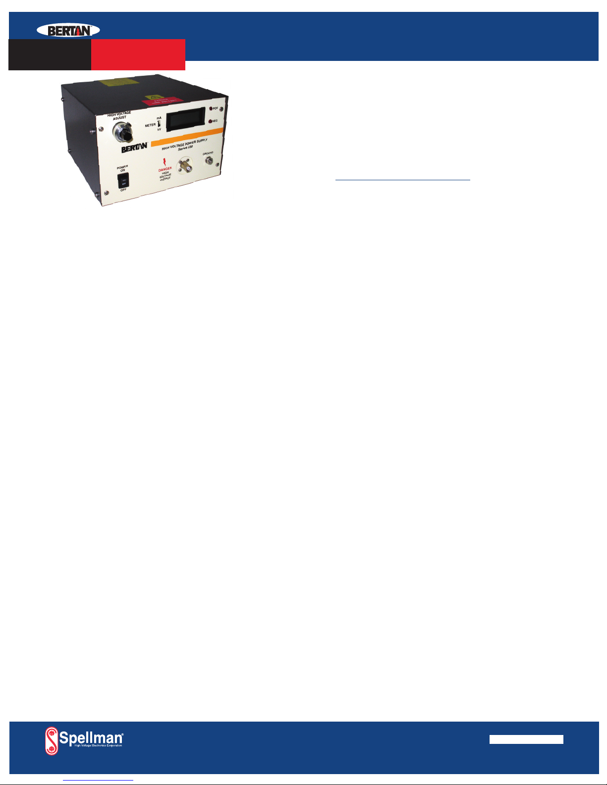
Spellman’s Bertan brand of 230 Series high voltage power
supplies provide regulated high voltage outputs from 1 to
30kV. The low noise, linear topology employed results in
extremely low output ripple specifications. These 12 to 15
watt units are inherently reversible by design, providing
either positive or negative output polarity. The 230 Series is
fully arc and short circuit protected. Excellent regulation
specifications are featured along with outstanding stability
performance.
TYPICAL APPLICATIONS
HiPot Testing
Electrostatics
General Laboratory Usage
SPECIFICATIONS
Input Voltage:
115Vac, ±10%, 50/60 Hertz @ 0.5 amp
230Vac, ±10%, 50/60 Hertz @ 0.25 amps
Input voltage is switch selectable
Output Voltage:
See “model selection” table
Output Polarity:
All units are reversible polarity by design
Output Current:
See “model selection” table
Voltage Regulation:
Line: ≤0.002% of rated output voltage over specified
input voltage range
Load:≤0.005% of rated output voltage for a full load
change
Current Regulation:
Internally set to limit at less than 125% of rated current.
A rear panel switch allows limiting at 25% of rated full current.
Ripple:
See “model selection” table
Temperature Coefficient:
≤100ppm/°C
Stability:
≤0.01%/hour, 0.02% per 8 hours after a 1/2 hour warm up
Accuracy:
Front panel control: ±(0.2% of setting + 0.2% of maximum)
Front panel Meter: Voltage ±(0.5% of setting + 0.5% of
maximum), Current ±(2% of setting + 0.5% of maximum)
Remote Programming: ±(0.1% of setting + 0.1% of maximum)
Voltage Monitor: ±(0.1% of reading + 0.1% of maximum)
Current Monitor: ±(2% of reading + 1% of maximum)
Front Panel Metering and Controls:
Power ON/OFF switch
3.5 digit metering for voltage and current, switch selectable
Polarity indicator
10 turn locking potentiometer to set output voltage
HV output connector
Ground stud
Operating Temperature
0°C to +50°C
Storage Temperature:
-40°C to +85°C
Humidity:
20% to 85% RH, non-condensing
Input Line Connector:
IEC320 EMI filter/input connector, a detachable
line cord is provided
Interface Connector:
9 pin “D” connector, a mating connector is provided
Output Connector:
A detachable 10 foot (3 meter) HV cable is provided
for units up to 5kV; 10kV through 20kV: 59” (1.5 meter);
30kV: 10 foot (3 meter)
Cooling:
Convection cooled
Dimensions
7.63˝ W X 5.03˝ H X 8.91˝ D
(194mm X 128mm X 226mm)
Weight:
≤10 pounds (4.5kg)
Regulatory Approvals:
Compliant to 2004/108/EC, the EMC Directive and
2006/95/EC, the Low Voltage Directive.
230
HIGH VOLTAGE
POWER SUPPLY
• MODULAR BENCH TOP DESIGN
• LOW RIPPLE AND NOISE
• 3.5 DI GIT FRONT PANEL DIGITAL METERING
• REVERSIBLE OUTPUT POLARITY
USA +1-631-630-3000 FAX: +1-631-435-1620
UK +44 (0)1798 877000 FAX: +44 (0)1798 872479
JAPAN +81 (0)48-447-6500 FAX: +81 (0)48-447-6501
CHINA +86 (0)512-67630010 FAX: +86 (0)512-67630030
e-mail: sales@spellmanhv.com
www.spellmanhv.com
128051-001 REV.D
Spellman High Voltage is an ISO 9001:2000 and ISO 14001:2004 registered company
www.spellmanhv.com/manuals/230
Page 3
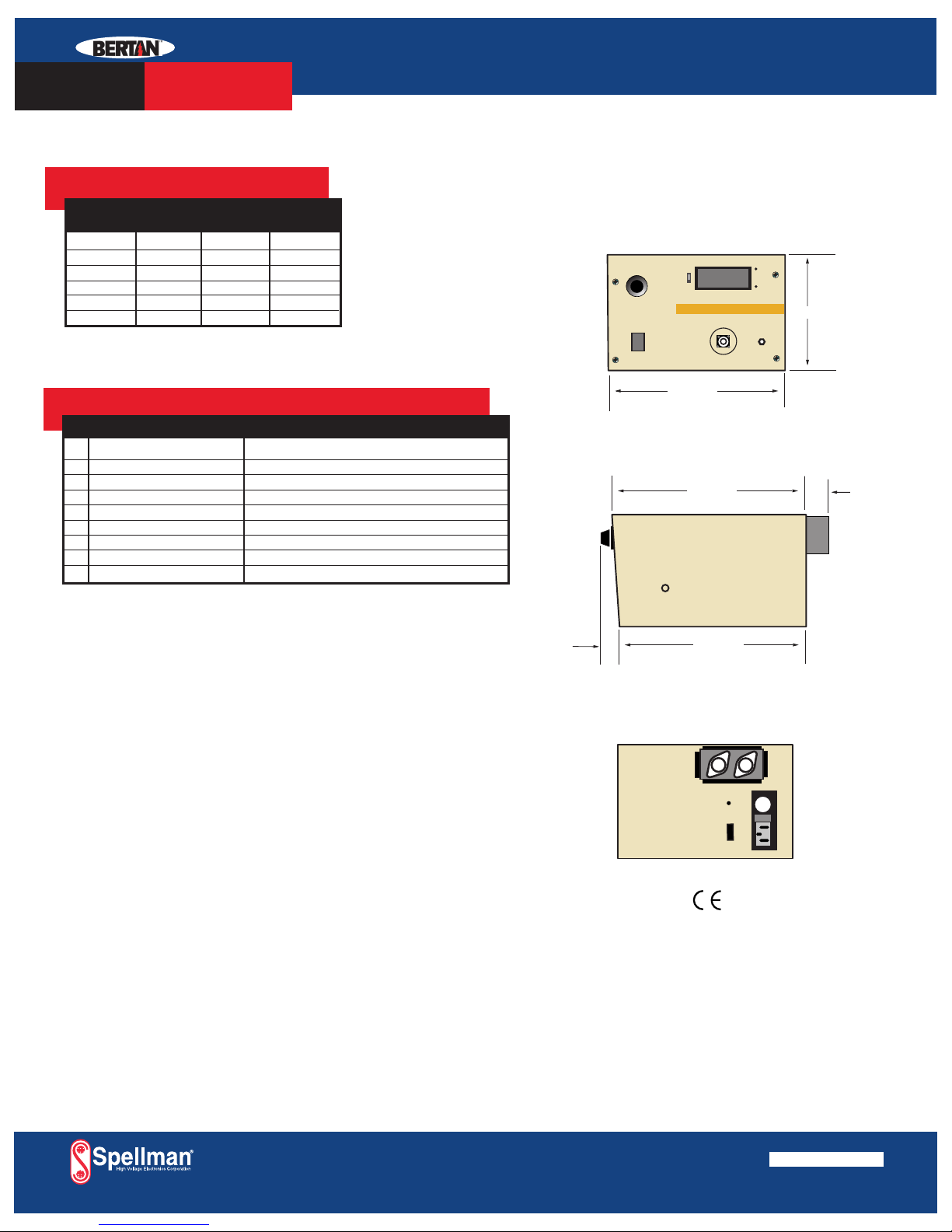
FRONT VIEW
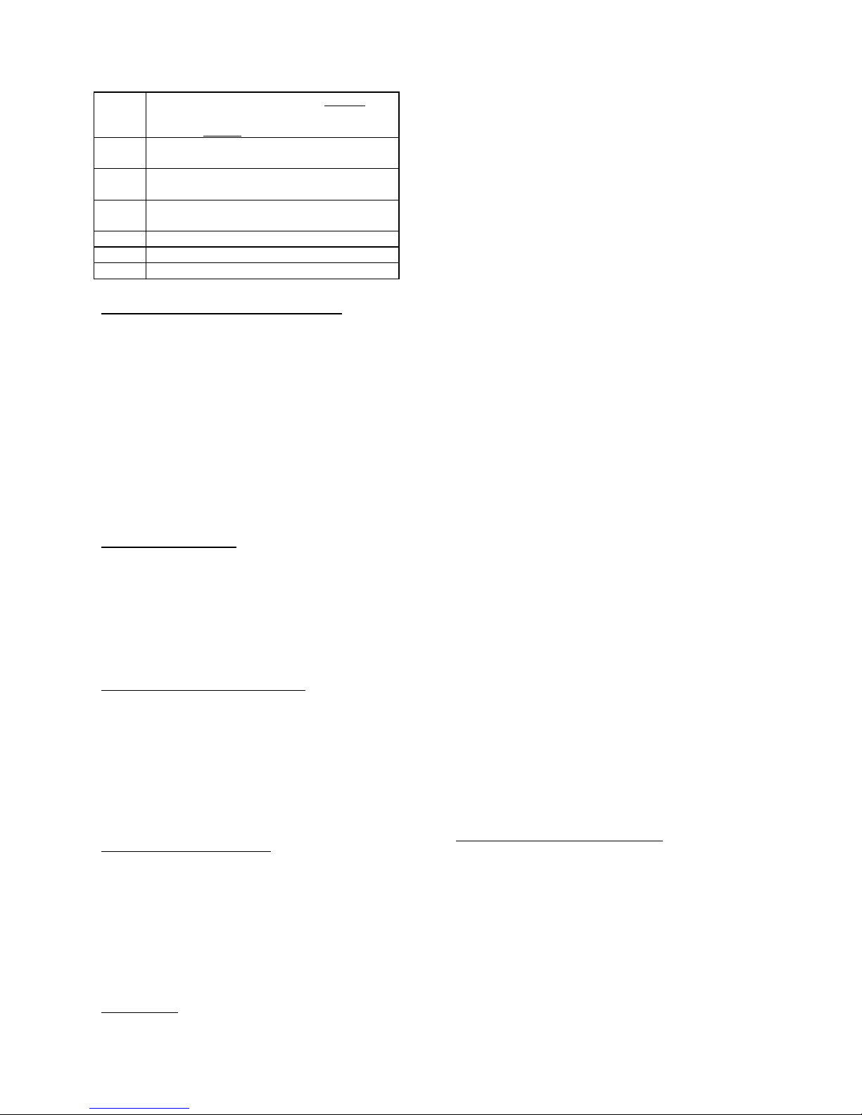
BACK VIEW
SIDE VIEW
HV CONN
POS NEG
METER
OFF
POWER
ON
PCS
VFS
GROUND
HIGHVOLTAGE
ADJUST
7.63 194]
5,03 [128]
1.0 [25]
.66 [17]
8.50 [216]
8.25 [210]
PAGE 2 OF 2
MODEL SELECTION TABLE
230 Voltage Current Ripple
Series
230-01R 0 to 1kV 0 to 15mA 10mV
230-03R 0 to 3kV 0 to 5mA 30mV
230-05R 0 to 5kV 0 to 3mA 50mV
230-10R 0 to 10kV 0 to 1.5mA 500mV
230-20R 0 to 20kV 0 to 0.5mA 2 volts
230-30R 0 to 30kV 0 to 0.4mA 5 volts
INTERFACE CONNECTOR
PIN SIGNAL PARAMETERS
1 Voltage Monitor 0 to 5Vdc = 0 to 100% rated voltage, Zout = 10KΩ
2 n/c none
3 Enable TTL “0” disables HV, TTL “1” or open enables HV
4 +5Vdc Reference +5.0Vdc @ 10mA, maximum
5 Current Monitor 0 to 5Vdc = 0 to 100% rated current, Zout = 10KΩ
6 Voltage Program Input 0 to 5Vdc = 0 to 100% rated voltage, Zin = 1MΩ
7 Analog Ground Ground
8 Digital Ground Ground
9 Polarity Indicator Open collector, 30V @ 25mA, positive = ON
DIMENSIONS: in.[mm]
S P E L L M A N H I G H V O LTA G E E L E C T R O N I C S C O R P O R AT I O N
230
HIGH VOLTAGE
POWER SUPPLY
OPTIONS:
Isolated (Floating) Output-Option F
Units up to and including 5kV can be provided with differential outputs
capable of floating up to ±2kV from ground. Voltage programming and
monitoring functions normally referenced to ground. Current monitoring
and metering is eliminated. Replace “R” suffix with “F” for this option.
USA +1-631-630-3000 FAX: +1-631-435-1620
UK +44 (0)1798 877000 FAX: +44 (0)1798 872479
JAPAN +81 (0)48-447-6500 FAX: +81 (0)48-447-6501
CHINA +86 (0)512-67630010 FAX: +86 (0)512-67630030
e-mail: sales@spellmanhv.com
www.spellmanhv.com
128051-001 REV.D
Spellman High Voltage is an ISO 9001:2000 and ISO 14001:2004 registered company
Page 4

IMPORTANT SAFETY PRECAUTIONS
SAFETY
THIS POWER SUPPLY GENERATES VOLTAGES THAT ARE DANGEROUS AND MAY BE FATAL.
OBSERVE EXTREME CAUTION WHEN WORKING WITH THIS EQUIPMENT.
High voltage power supplies must always be grounded.
Do not touch connections unless the equipment is off and the
Capacitance of both the load and power supply is discharged.
Allow five minutes for discharge of internal capacitance of the power supply.
Do not ground yourself or work under wet or damp conditions.
SERVICING SAFETY
.
Maintenance may require removing the instrument cover with the power on.
Servicing should be done by qualified personnel aware of the electrical hazards.
WARNING note in the text call attention to hazards in operation of these units
that could lead to possible injury or death.
CAUTION notes in the text indicate procedures to be followed to avoid possible
damage to equipment.
Copyright © 2000, Spellman High Voltage Electronics Corporation. All Rights Reserved.
This information contained in this publication is derived in part from proprietary and patent data. This information has
been prepared for the express purpose of assisting operating and maintenance personnel in the efficient use of the
model described herein, and publication of this information does not convey any right to reproduce it or to use it for
any purpose other than in connection with installation, operation, and maintenance of the equipment described.
118004-001 REV. B
Page 5

WICHTIGE SICHERHEITSHINWEISE
SICHERHEIT
DIESES HOCHSPANNUNGSNETZTEIL ERZEUGT LEBENSGEFÄHRLICHE HOCHSPANNUNG.
SEIN SIE SEHR VORSICHTIG BEI DER ARBEIT MIT DIESEM GERÄT.
Das Hochspannungsnetzteil muß immer geerdet sein.
Berühren Sie die Stecker des Netzteiles nur, wenn das Gerät ausgeschaltet ist und die elektrischen
Kapazitäten des Netzteiles und der angeschlossenen Last entladen sind.
Die internen Kapazitäten des Hochspannungsnetzteiles benötigen ca. 5 Minuten, um sich zu entladen.
Erden Sie sich nicht, und arbeiten Sie nicht in feuchter oder nasser Umgebung.
SERVICESICHERHEIT
Notwendige Reparaturen können es erforderlich machen, den Gehäusedeckel während des Betriebes zu
entfernen.
Reparaturen dürfen nur von qualifiziertem, eingewiesenem Personal ausgeführt werden.
“WARNING” im folgenden Text weist auf gefährliche Operationen hin, die zu Verletzungen oder zum Tod
führen können.
“CAUTION” im folgenden Text weist auf Prozeduren hin, die genauestens befolgt werden müssen, um
eventuelle Beschädigungen des Gerätes zu vermeiden.
118004-001 REV. B
Page 6

PRECAUTIONS IMPORTANTES POUR VOTRE SECURITE
CONSIGNES DE SÉCURITÉ
CETTE ALIMENTATION GÉNÈRE DES TENSIONS QUI SONT DANGEUREUSES ET PEUVENT ÊTRE FATALES.
OYEZ EXTRÊMENT VIGILANTS LORSQUE VOUS UTILISEZ CET ÉQUIPEMENT.
S
Les alimentations haute tension doivent toujours être mises à la masse.
Ne touchez pas les connectiques sans que l’équipement soit éteint et que la capacité à la fois de la charge et de
l’alimentation soient déchargées.
Prévoyez 5 minutes pour la décharge de la capacité interne de l’alimentation.
Ne vous mettez pas à la masse, ou ne travaillez pas sous conditions mouillées ou humides.
CONSIGNES DE SÉCURITÉ EN CAS DE REPARATION
La maintenance peut nécessiter l’enlèvement du couvercle lorsque l’alimentation est encore allumée.
Les réparations doivent être effectuées par une personne qualifiée et connaissant les risques électriques.
Dans le manuel, les notes marquées « WARNING » attire l’attention sur les risques lors de la manipulation de ces
équipements, qui peuvent entrainer de possibles blessures voire la mort.
Dans le manuel, les notes marquées « CAUTION » indiquent les procédures qui doivent être suivies afin d’éviter
d’éventuels dommages sur l’équipement.
118004-001 REV. B
Page 7

IMPORTANTI PRECAUZIONI DI SICUREZZA
SICUREZZA
QUESTO ALIMENTATORE GENERA TENSIONI CHE SONO PERICOLOSE E
POTREBBERO ESSERE MORTALI.
PONI ESTREMA CAUTELA QUANDO OPERI CON QUESO APPARECCHIO.
Gli alimentatori ad alta tensione devono sempre essere collegati ad un impianto di terra.
Non toccare le connessioni a meno che l’apparecchio sia stato spento e la capacità interna
del carico e dell’alimentatore stesso siano scariche.
Attendere cinque minuti per permettere la scarica della capacità interna dell’alimentatore
ad alta tensione.
Non mettere a terra il proprio corpo oppure operare in ambienti bagnati o saturi d’umidità.
SICUREZZA NELLA MANUTENZIONE.
Manutenzione potrebbe essere richiesta, rimuovendo la copertura con apparecchio
acceso.
La manutenzione deve essere svolta da personale qualificato, coscio dei rischi elettrici.
Attenzione alle AVVERTENZE contenute nel manuale, che richiamano all’attenzione ai
rischi quando si opera con tali unità e che potrebbero causare possibili ferite o morte.
Le note di CAUTELA contenute nel manuale, indicano le procedure da seguire per evitare
possibili danni all’apparecchio.
118004-001 REV. B
Page 8

TABLE OF CONTENTS
Paragraph Title Page
SECTION 1 - GENERAL INFORMATION
1.1 Purpose of the Equipment 2
1.2 Description 2
1.3 Options 2
1.4 Safety Terms 2
SECTION 2 - OPERATION
2.1 Installation 2
2.2 Front Panel Controls and Displays 2/3
2.3 Rear Panel Controls, Connectors and Terminals 3
2.4 Polarity Reversing 3
2.5 Preparations for Use 3/4
2.6 Local Operation 4
2.7 Remote Operation 4/5
2.8 Computer Programming 5/6
2.9 Input Power 6
2.10 Current Limiting 6/7
2.11 High Voltage Output 7
SECTION 3 - THEORY OF OPERATION
3.1 Functional Description 7
3.2 Circuit Description 7
3.3 Current Capability 7/8
SECTION 4 - MAINTENANCE
4.1 General 8
4.2 Cleaning 8
4.3 Calibration 8
SECTION 1 GENERAL INFORMATION
Installation and Instruction Manual - Series 230 Page 1 118128-001 Rev A
Page 9

1.1 PURPOSE OF THE EQUIPMENT
The Series 230 is a family of regulated precision
laboratory high voltage power supplies. They
provide exceptional performance in critical
applications such as nuclear and electro-optical
instrumentation, precision CRT and electron
beam applications.
SECTION 2 OPERATION
2.1 INSTALLATION
WARNING!
This unit produces hazardous
voltage. Do not apply line voltage input unless
adequate ground is connected to the unit and
the high voltage output has been properly
connected.
1.2 DESCRIPTION
The Series 230 is a family of compact bench top
power supplies with output voltages up to 30
kV. The units consist of a DC power supply that
converts the AC line power to a low DC voltage
and a DC to DC converter that generates the
high DC output voltage. Low voltage electronic
solid-state circuitry is mounted on the PCB100,
and the high voltage assembly is fully
encapsulated for reliable, arc-free, operation.
These stable, low noise high voltage power
supplies feature front panel digital voltage and
current metering, and calibrated direct-reading
front panel controls. The high voltage output is
also obtainable from the front panel. The rear
panel features a connector for remote analog
programming and output voltage and output
current monitoring, line power plug, fuse,
and AC voltage selection switch. All units have
arc and short circuit protection for safe, reliable,
and arc-free operation. Although primarily
designed for rack mounting, the unit may also be
used in benchtop applications.
1.3 OPTIONS
Isolated Floating Output
Units can be provided with the output capable of
floating up to r2kV from ground. All controls,
programming and monitoring functions operate
normally, referenced to ground. The high
voltage output polarity, with respect to the
floating input terminal is reversible.
1.4 SAFETY TERMS
The WARNING used in this manual explains
dangers that could result in personal injury or
death.
2.2 FRONT PANEL CONTROLS AND
DISPLAYS
Output Connector:
The HV output connector on the 1kV through
5kV models mate with a shielded mating
connector supplied with each unit. Refer to the
specifications on page 12 to identify the mating
connector. Assembly procedures for mating
connectors are given at the end of this manual.
On 10kV through 30kV models, an unshielded,
preassembled high voltage cable connected to
the appropriate connector is provided with each
unit. Only the proper mating connector should
be used with the indicated power supply and the
power supply should NEVER be energized
without a mating connector and suitable load
connected.
Power Switch:
A rocker switch turns the line power on or off to
the entire instrument. The display panel will be
lit when line power is applied to the unit.
Output Meter:
The digital output meter can display the output
current or the output voltage. A switch below
the meter allows the operator to select which
output parameter to monitor. The accuracy of
the meter is given in the specification (see page
12).
Polarity Indicator:
An LED on the front panel display indicates the
polarity of the output. The appropriate LED is
lit as soon as line power is applied regardless of
whether high voltage output is enabled or
disabled. To change the polarity setting, see
paragraph 2.4.
The CAUTION used in this manual explains
hazards that could damage the instrument.
Installation and Instruction Manual - Series 230 Page 2 118128-001 Rev A
Voltage Control:
Page 10

A continuous multi-turn digital dial is used to
adjust the high voltage output. The resolution
0.2% of maximum.
2.3 REAR PANEL CONTROLS,
CONNECTORS, AND TERMINALS
Gnd:
Ground is connected to the case of the Series
230.
Fuse:
The fuse is the ac line power fuse. It is rated for
1A, 250Vac for 105Vac-125Vac operation and
0.5A, and 250Vac for 210Vac-250Vac
operation. Should a fuse ever need replacement,
only these values should be used unless
otherwise advised by a qualified BERTAN
service technician.
Line Voltage Selector:
The line voltage selector selects the appropriate
line voltage 105Vac-125Vac or 210Vac-250Vac
at 50-60 Hz. By default, power supplies are
shipped from the factory in the 105-125V
position. Before energizing your power supply,
verify that the line voltage selector switch is in
the proper position for your mains input.
AC Line Plug:
The IEC 320 line plug receptacle accepts a
three-wire female line plug for ac line power.
mechanism that is easily accessible upon
removal of the top cover. The polarity reversal
module is a clear plastic assembly identified by
the exiting silicone high voltage cables. It is a
two-part assembly. To change the polarity, turn
off power supply, remove all cover screws
holding the top cover on and:
a. Remove the two diagonally opposed screws
fastening the top portion of the module
assembly to the bottom portion. NOTE: DO
NOT DESOLDER WIRES OR PINS.
b. Carefully separate the module by pulling
the top portion from the bottom portion.
The module portions are fitted very snugly
and removal may be eased by slightly
rocking the assembly.
c. Rotate the top portion of the module
assembly 180q, taking care not to unduly
stress the high voltage cables.
d. Rejoin the 2 portions of the module
assembly. Make sure that the top portion is
entirely seated to the bottom portion.
NOTE: An interlock automatically insures
that the high voltage cannot be applied until
the portions of the module are properly
mated.
e. Resecure the top portion to the bottom
portion of the Polarity Reversal Module
Assembly.
f. Re-cover the power supply.
WARNING!
three-wire grounded line cord. This must be
used with a three-wire receptacle where the
"third wire" is connected to earth ground;
otherwise personal injury or death may occur.
This unit is equipped with a
2.5 PREPARATION FOR USE
WARNING!
Before energizing your power
supply, thoroughly review and follow these
procedures. Failure to do so may result in
damage to equipment and injury or death to
personnel.
2.4 POLARITY REVERSING:
WARNING!
power supply’s polarity, the power supply must
Before attempting to reverse the
To prepare the Series 230 for use, use the
following procedure:
be turned off and the output fully discharged.
Failure to follow these procedures may result
in damage to the power supply, associated test
Set the Series 230 for the appropriate line
voltage as specified in Section 2.3.
equipment and/or personnel.
Connect a ground strap from case ground (on the
For 1kV to 5kV output models, a screwdriver-
rear panel) to a system common.
adjustable POLARITY SELECTOR SWITCH is
accessible at the rear panel of the unit, next to
the HV output connector. For 10kV to 50kV
Select the appropriate HV output polarity for the
application.
output models, the polarity of the HV output is
reversible by means of an internal switching
Installation and Instruction Manual - Series 230 Page 3 118128-001 Rev A
Page 11

Set the front panel controls to:
a. Power Switch - OFF
b. Output Voltage Switch(s) – 0 (205B
only).
c. Multi Turn Digital Dial - 000 (fully
counterclockwise)
Set the LOCAL/REMOTE (ANALOG/
DIGITAL) rear panel switches (205B only) to:
a. LOCAL for local front panel
operation.
b. REMOTE/ANALOG for remote
analog operation. Note: Selecting the
REMOTE control will override all local
front panel controls of the output.
c. REMOTE/DIGITAL for Computer
Programming if equipped with a CBNY
option. Reference Section 2.7.
Plug the line cord into the power line with a
three-wire IEC receptacle to maintain proper
case ground.
WARNING!
This unit is equipped with a
three-wire grounded line cord. This must be
used with a three-wire receptacle where the
"third wire" is connected to earth ground;
otherwise personal injury or death may occur.
Connect the output of the Series 230 to the
circuit. Use a properly rated shielded cable with
the supplied HV output connector to insure good
circuit connections and safe operation. Refer to
Section 2.10.
WARNING!
Prior to connecting or removing
any equipment from the High Voltage power
supply, always return the Output Voltage
Control(s) to 0V prior to applying or removing
power. External circuits may retain voltage
after controls are set to zero. Discharge any
residual voltage before connecting or removing
any equipment.
is reached. Apply power to the load by
switching the High Voltage - ON. The output
will quickly reach the value set by the controls.
Full stability will be achieved after
approximately 30 minutes.
2.7 REMOTE OPERATION
PROGRAM CONTROL SWITCH:
Before the Series 230 can be remotely
programmed, the instrument must be configured
by setting the rear panel PROGRAM
CONTROL SWITCH (S102) to the REMOTE
ANALOG position (206B is only programmable
through the rear panel and therefore S101 is
omitted). All monitoring and enable functions
are active, independent of the S102 switch, as
are the front panel meters. When in remote
mode the front panel controls are inactive.
REMOTE PROGRAMMING:
The high voltage output can be remotely
programmed from either an external voltage
source or with an external potentiometer using
the internal reference voltage source (Pin 4). A
0 to +5Vdc programming voltage applied to Pin
6 of J107 (PROGRAMMING/MONITOR)
connector jack on the rear panel will remotely
program the high voltage output from zero to
maximum output. Programming can also be
accomplished using a potentiometer connected
between Pin 4 (+5Vdc), Pin 7 (GND) and with
the wiper connected to Pin 6 (PRGM INPUT).
The potentiometer should be a low temperature
coefficient wirewound or cermet type, 5k: to
20k: resistance values. The power supply
output will be proportional to the programming
input. The programming input impedance is
greater than 1M:. TABLE 2.1 below lists the
PROGRAMMING / MONITOR connector pin
designations. The accuracy of the remote
programming is detailed in the specifications.
2.6 LOCAL OPERATION
Turn POWER - ON to the instrument. Slowly
increase the output voltage using the appropriate
Voltage Control(s) until the desired output level
Installation and Instruction Manual - Series 230 Page 4 118128-001 Rev A
TABLE 2.1 - J107 PIN DESIGNATIONS
PIN # FUNCTION
1 Output voltage monitor, buffered, 0 to +5Vdc
(output impedance 10k:)
2 No connection
Page 12
3 Enable/Disable. Input logic zero disables high
voltage generation. Open circuit or input
logic one enables
4 Precision +5Vdc reference output referenced
to analog ground.
5 Output current monitor, buffered, 0 to +5Vdc
(output impedance 10k:)
6 Remote analog voltage programming input, 0
to +5Vdc
7 Analog Ground
8 Digital Ground
9 Polarity Indicator
high voltage generation.
REMOTE ANALOG MONITORING:
Buffered, analog output monitors, 0 to + 5Vdc,
linearly proportional to the power supply's
voltage and current output are provided. To
monitor the output voltage, connect a high
impedance meter to pin 1 and pin 7 (ground). To
monitor the output current, connect a high
impedance meter to pin 5 and pin 7 (ground).
The accuracy of the voltage and current
monitors is given in the specifications (see page
12). The monitor output impedance is
approximately 10k:.
All Series 230 instruments can be provided with
a factory-installed option for remote digital
programming of the high voltage output. The
programming inputs are TTL compatible and the
data is positive logic (all data bits low yield 0
high voltage output). The addition of this option
allows the unit to be easily interfaced to any
computer or microprocessor utilizing one of its
three user selectable modes of operation.
16 Bit Transparent: The 16 bit data is passed
from the inputs directly to the DAC. This is the
default mode (is 100% compatible with all
previous CBNY digital programming boards).
16 Bit Register: The 16 bit data is latched into an
internal 16-bit register in one write cycle.
8 Bit Register: Two 8-bit bytes (Most
Significant Byte and Least Significant Byte) are
latched into two 8-bit registers. The MSB and
LSB registers are individually addressed and
written. This allows an 8 bit data bus system to
provide 16 bit programming in two write cycles.
ENABLE/DISABLE:
A TTL level logic TRIP input signal can be used
to enable or disable the power supply output
remotely. Input logic zero or grounding pin 3
disables high voltage generation. Open circuit or
input logic one on pin 3 enables high voltage
generation.
+5Vdc REFERENCE OUTPUT:
A precision +5Vdc reference output is provided
on pin 4 for the user’s convenience. This fixed
output can be used for remote resistance
programming (see REMOTE
PROGRAMMING, above) or various control
functions. This output is referenced to analog
ground (pin 7).
POLARITY INDICATOR:
A TTL polarity indicator output signal is
available at pin 9. An NPN open collector
connection with respect to digital ground
indicates the high voltage output polarity. NPN
saturation denotes positive polarity.
2.8 COMPUTER PROGRAMMING
(Optional)
GENERAL:
The register modes utilize standard Chip Select
and Write Enable protocol allowing the CBNY
to act as a memory mapped register or an I/O
port attached directly to an 8 or 16 bit
microprocessor system bus. In addition, any
standard unit in the Series 230 can be computer
programmed and monitored using the Bertan BHiVE minicomputer controlled enclosure with
the appropriate interface module. Remote TTY
or RS-232C control at selectable 110 to 9600baud rate is possible. A separate IEEE-488
interface is also available for use with the Series
205B high voltage power supplies. See the
Model 200-C488 data sheet for complete
information.
FUNCTIONAL DESCRIPTION:
Connector J3 (Amphenol 57-40240) accepts the
remote binary coded inputs and is located on the
rear panel. When the REMOTE/LOCAL switch
is in the REMOTE DIGITAL position, control
of the unit is dependent upon the digital signals
present at Pin 2 through Pin 17 of J3. Pin 2 is
for the most significant bit, with increasing pin
numbers having lower significant bits. Pin 17 is
the least significant bit input. Positive logic is
Installation and Instruction Manual - Series 230 Page 5 118128-001 Rev A
Page 13

used, with logic 0 on all 16 data lines needed for
0 volts output.
The incremental resolution is a function of the
power supply's maximum output. The
resolution for different models in the Series is
listed in TABLE 2.2 below.
TABLE 2.2 – SERIES 230 DIGITAL
PROGRAMMING RESOLUTION
º
-01R 0.02V
-03R 0.05V
-05R 0.08V
-10R 0.16V
-20R 0.31V
-30R 0.50V
-50R 0.80V
Pin 23: Enable. If strapped to "0" or open the
output of the latch (input of the DAC) is at high
impedance and the input of the DAC set to zero.
If strapped to "1" the output of the latch is
enabled and the data at the input of the DAC is
dependant on the CS WR and F/L.
Pin 24: F/L-Latch/Follow. If strapped to "0" the
device operates in a latching mode where data
on the data bus is latched into on board latches
by a write pulse. If strapped to "1" or left open,
the data at the input to the D to A follows the
data on the data bus regardless of the levels on
CS, WR or BS. The 16/8 must be open or
strapped to "1" when in the follow mode or the
most significant byte to the DAC will be
identical to the least significant byte input.
OPERATION:
In addition to the 16 data lines, J3 contains
ground and +5Vdc output on Pins 21 and 22
respectively, and five control lines described
below. The +5Vdc and ground allow remote
control via an external digitally coded switch.
The digital data at the input can continuously
control the power supply output high voltage.
The detailed functions of the control inputs are
described below.
Pin 01: 16/8. If strapped to "1" or left open the
device operates as a 16 bit parallel input. If
strapped to "0" the device operates as an 8 bit
parallel bus with the BS input selecting the byte
being written.
Pin 18: CS-Chip Select (device select). When
"0" the data on the bus may be written into the
latches by the WR signal.
Pin 19: WR-Write. When "0" with CS, "0" the
input to the DAC the data on the bus. When the
first CS or WR is returned to "1" the data
present on the bus is latched into the DAC.
Pin 20: BS-Byte Select. If the 16/8 input is
strapped to "0", a "1" on the BS selects the least
significant byte to write data to. If BS is "0"
data is written to the most significant byte. If
16/8 input is "1" or open the BS lead has no
effect.
Byte select must be valid at least 25ns before
WR goes low and remain valid at least 40ns
after the first of CS or WR to go high.
All timing is from the latter of CS or WR going
low and from earlier of CS or WR going high.
The minimum common low time of WR and CS
is 40ns. Data must be valid at least 125ns before
the earlier of CS or WR goes high and remain
valid at least 20ns after that time.
2.9 INPUT POWER
Input AC line voltage required is
115Vac/230Vac r10%, 50-60Hz, single phase.
The recessed LINE VOLTAGE selector switch
on the rear panel selects either 115 Vac or 230
Vac operation. By default, power supplies are
shipped from the factory in the 115Vac position.
Before energizing your power supply, verify that
this switch is in the proper position for your
mains input.
2.10 CURRENT LIMITING
The Series 230 includes a current limiting circuit
that drops the output voltage to a safe level
when the rated output current is exceeded by
approximately 5%. (See specification on
Current Capability when operating the unit at
reduced output voltages or when operating in a
current limit mode for capacitor charging).
2.11 HIGH VOLTAGE OUTPUT
Installation and Instruction Manual - Series 230 Page 6 118128-001 Rev A
Page 14

The high voltage output connector is located on
the rear panel. An appropriate shielded mating
connector is supplied with each unit. These
connectors are as listed in Table 2.3. Refer to
pages 13-16 for the mating connector assembly
instructions. Only the proper mating connector
should be used with the indicated power supply
and the power supply should never be energized
without a mating connector and suitable load
connected.
voltage power supplies. The B+ supply is a
filtered full wave rectifier circuit located on the
chassis. The regulated low voltage power
supply circuit (+12Vdc) consists of a rectifier
circuit located on T1 and output regulators
located on the PCB 100.
The output of the oscillator circuit is amplified
in the AGC amplifier. The gain of the AGC
amplifier is a function of the control voltage
developed at the output of the error amplifier.
TABLE 2.3: SERIES 230 HIGH VOLTAGE
CONNECTORS
MODEL OUTPUT MATING
-01R JDK PDB
-03R JDK PDB
-05R JDK PDB
-10R JJA 405787
-20R JJA 405787
-30R JJA 405787
-50R JJB 405786
SECTION 3
THEORY OF OPERATION
3.1 FUNCTIONAL DESCRIPTION
The circuit uses a DC to DC converter that
converts low voltage DC power to a high
voltage DC output. This output voltage is
highly regulated and filtered and can be varied
either by the front panel controls or through the
REMOTE PROGRAM input on the rear panel.
The input to the DC to DC converter is obtained
from internal low voltage power supplies
powered by the AC line input.
An oscillator determines the frequency
(approximately 20kHz) at which all
amplification, high voltage transformation,
rectification and filtering occurs. The
amplification is a function of a control voltage
that performs the function of control and
regulation. A sample of the output voltage is
compared against a reference voltage in the
sensing circuit. The sensing circuit generates
the control voltage to set and maintain a fixed
high voltage output.
3.2 CIRCUIT DESCRIPTION
The input AC line is converted to the B+
(36Vdc) supply and regulated +12Vdc low
The encapsulated high voltage assembly
includes a high voltage power transformer,
rectifier or multiplier circuits, ripple filter and
sensing circuits. These are all critical custom
designed and encapsulated components.
A sample of the high voltage DC output is fed to
the output voltage sensing circuit and is
compared to a command voltage. Output
voltage control is obtained by varying the
command voltage fed to the error amplifier. The
error amplifier compares the command voltage
and the signal from the output voltage sense
circuit. Any difference causes a correction in
the gain control of the AGC amplifier. The
command voltage is controlled by the front
panel controls when the rear panel program
switch is in the LOCAL position.
The reference and reference control and buffer
provide a stable +5Vdc to the front panel output
voltage controls.
The current sensing circuit monitors the output
current. The buffered output of this circuit is
employed for both internal and remote current
monitoring.
3.3 CURRENT CAPABILITY
The maximum current rating for each model, as
shown in the table to the left, is applicable when
the unit is operated at maximum output voltage.
When operated at reduced output voltage levels,
or when operating in a current limit mode for
charging capacitors, the output current must be
limited to reduced levels. This is required to
protect against excessive power dissipation of
the driver transistors.
The maximum output current must be linearly
derated from maximum output voltage to 30% of
Installation and Instruction Manual - Series 230 Page 7 118128-001 Rev A
Page 15

maximum current at zero output voltage.
Maximum output current available at any
desired voltage can be calculated by applying
the following formula:
Imax = Vset(.7Irated/Vrated)+.3Irated
When operating the power supply as a capacitor
charger (i.e., a capacitor is being continuously
discharged then recharged from zero voltage by
the power supply) use a charging resistor in
series with the power supply output. The
resistance should be equal to the power supply’s
maximum rated output voltage divided by the
maximum rated output current.
The above derating factors are safe for all
conditions and all models. Consult BERTAN
for special cases before exceeding these factors.
SECTION 4 MAINTENANCE
4.1 GENERAL
The Series 230 instrument should not require
any maintenance. It is designed for reliable,
trouble free operation. If any question should
arise, contact the Bertan Customer Service
Department for assistance or return
authorization. It is suggested that the unit be
returned to the factory if service should become
necessary.
4.3 CALIBRATION SERVICES
Your BERTAN high voltage power supply is
designed to provide many years of reliable
service. For a nominal charge it can be returned
to the factory for calibration and certification to
its original specification. For traceability, a
certificate will be issued, identifying the serial
number of the unit calibrated and all test
equipment used to perform the calibration. All
measurements are traceable to the National
Institute of Standards and Technology (NIST).
Calibration is guaranteed from 1 year of
issuance. Contact the factory at (516) 433-3110
or your local sales representative for additional
details.
4.2 CLEANING
Cleaning of the power supply should only be
performed with the supply disconnected from
the ac power source. A soft cloth moistened
with conventional ammonia-based cleaning
agents will suffice for all exposed surfaces. The
metal shell of the HV connector should be
cleaned with isopropyl alcohol.
If the supply is operated in a dusty environment,
an accumulation of dust/debris may build-up
inside the unit which may cause noisy operation
(i.e., “ticking” or minor crackling) in the area of
the HV cabling on the –10R through –50R. The
safest way to remove such debris is with
compressed air. Ensure that no dust/debris is
left behind in the insulative medium of the HV
output connector after this cleaning operation.
Such dust may be removed with a cotton swab
moistened with isopropyl alcohol.
Installation and Instruction Manual - Series 230 Page 8 118128-001 Rev A
Page 16

SPELLMAN HIGH VOLTAGE ELECTRONICS
WARRANTY
Spellman High Voltage Electronics (“Spellman”) warrants that all power supplies it manufactures will be
free from defects in materials and factory workmanship, and agrees to repair or replace, without charge, any
power supply that under normal use, operating conditions and maintenance reveals during the warranty
period a defect in materials or factory workmanship. The warranty period is twelve (12) months from the
date of shipment of the power supply. With respect to standard SL power supplies (not customized) the
warranty period is thirty-six (36) months from the date of shipment of the power supply.
This warranty does not apply to any power supply that has been:
• Disassembled, altered, tampered, repaired or worked on by persons unauthorized by Spellman;
• subjected to misuse, negligent handling, or accident not caused by the power supply;
• installed, connected, adjusted, or used other than in accordance with the original intended application and/or
instructions furnished by Spellman.
THE FOREGOING WARRANTY IS IN LIEU OF ALL OTHER WARRANTIES, EXPRESS OR IMPLIED, INCLUDING
THOSE OF MERCHANTABILITY OR FITNESS FOR A PARTICULAR PURPOSE.
The buyer’s sole remedy for a claimed breach of this warranty, and Spellman’s sole liability is limited, at
Spellman’s discretion, to a refund of the purchase price or the repair or replacement of the power supply at
Spellman’s cost. The buyer will be responsible for shipping charges to and from Spellman’s plant. The
buyer will not be entitled to make claim for, or recover, any anticipatory profits, or incidental, special or
consequential damages resulting from, or in any way relating to, an alleged breach of this warra nty.
No modification, amendment, supplement, addition, or other variation of this warranty will be binding unless
it is set forth in a written instrument signed by an authorized officer of Spellman.
For an authorization to ship contact Spellman’s Customer Service Department. Please state the model and
serial numbers, which are on the plate on the rear panel of the power supply and the reason for return. A
Return Material Authorization Code Number (RMA number) is needed from Spellman for all returns. The
RMA number should be marked clearly on the outside of the shipping container. Packages received without
an RMA Number may delay return of the product. The buyer shall pay shipping costs to and from Spellman.
Customer Service will provide the Standard Cost for out-of-warranty repairs. A purchase order for this
amount is requested upon issuance of the RMA Number (in-warranty returns must also be accompanied by
a “zero-value” purchase order). A more detailed estimate may be made when the power supply is received
at Spellman. In the event that the cost of the actual repair exceeds the estimate, Spellman will contact the
customer to authorize the repair.
Spellman will warrant for three (3) months or balance of product warranty, whichever is longer, the repaired
assembly/part/unit. If the same problem shall occur within this warranty period Spellman shall undertake all
the work to rectify the problem with no charge and/or cost to the buyer. Should the cause of the problem be
proven to have a source different from the one that has caused the previous problem and/or negligence of
the buyer, Spellman will be entitled to be paid for the repair.
For a complete listing of Spellman’s Global Service facilities please go to:
http://www.spellmanhv.com/customerservice/service.asp
Factory Service Procedures
Factory Service Warranty
Spellman Worldwide Service Centers
101520-007 REV D
 Loading...