

Page 1
For use with:
R15 / M15 receivers and T15 Photo transmitter
Up to 15m sensing range
with standard M/R sensors
DIN rail mounting
Terminal block wiring
Relay changeover contact rated
8A/250VAC
Test input for functional test
™
ST-D.O.T.
ST-DOT-120
Opto Amplifier
Installation guide
Page 2
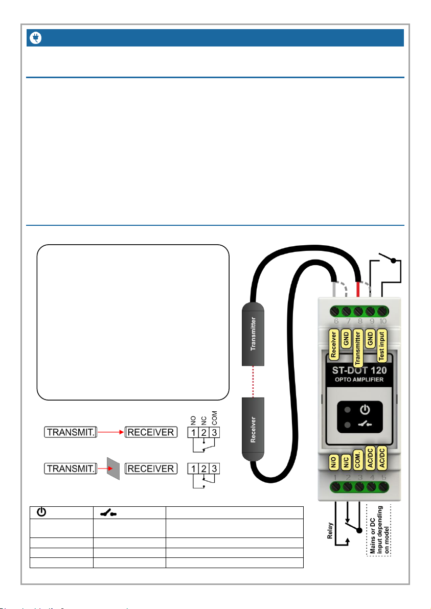
I N T R O D U C T I O N AND W I R I NG
Install receiver closest to the ST-DOT
120. (White wire)
Avoid running any wires close/in
parallel to any motor power cables i.e.
the output from a frequency inverter
drive.
Always use M15 type receiver when
using with frequency inverter
Avoid installing the receiver in direct
sunlight.
Status Led’s:
- Status:
- Relay:
Description:
Green Solid
Green Flash
Beam not interrupted. Flash rate
indicated signal strength.
Green Solid
Red Solid
Beam interrupted
Red Solid
Red Solid
Test signal active
Red Flash
Red Flash
Receiver connection fault
Introduction:
ST-DOT-120 is an opto-electronic amplifier module for DIN-rail
mounting for use with DOT transmitters and receivers.
It is a single channel amplifier with relay output made for a variety of
supply voltages. It is quick and easy to install. Just connect power,
transmitter, receiver and output and it is ready to operate.
When transmitter and receiver do see each other the relay will be
standing N.O. When the light is interrupted the relay will switch to N.C.
Wiring:
Page 3
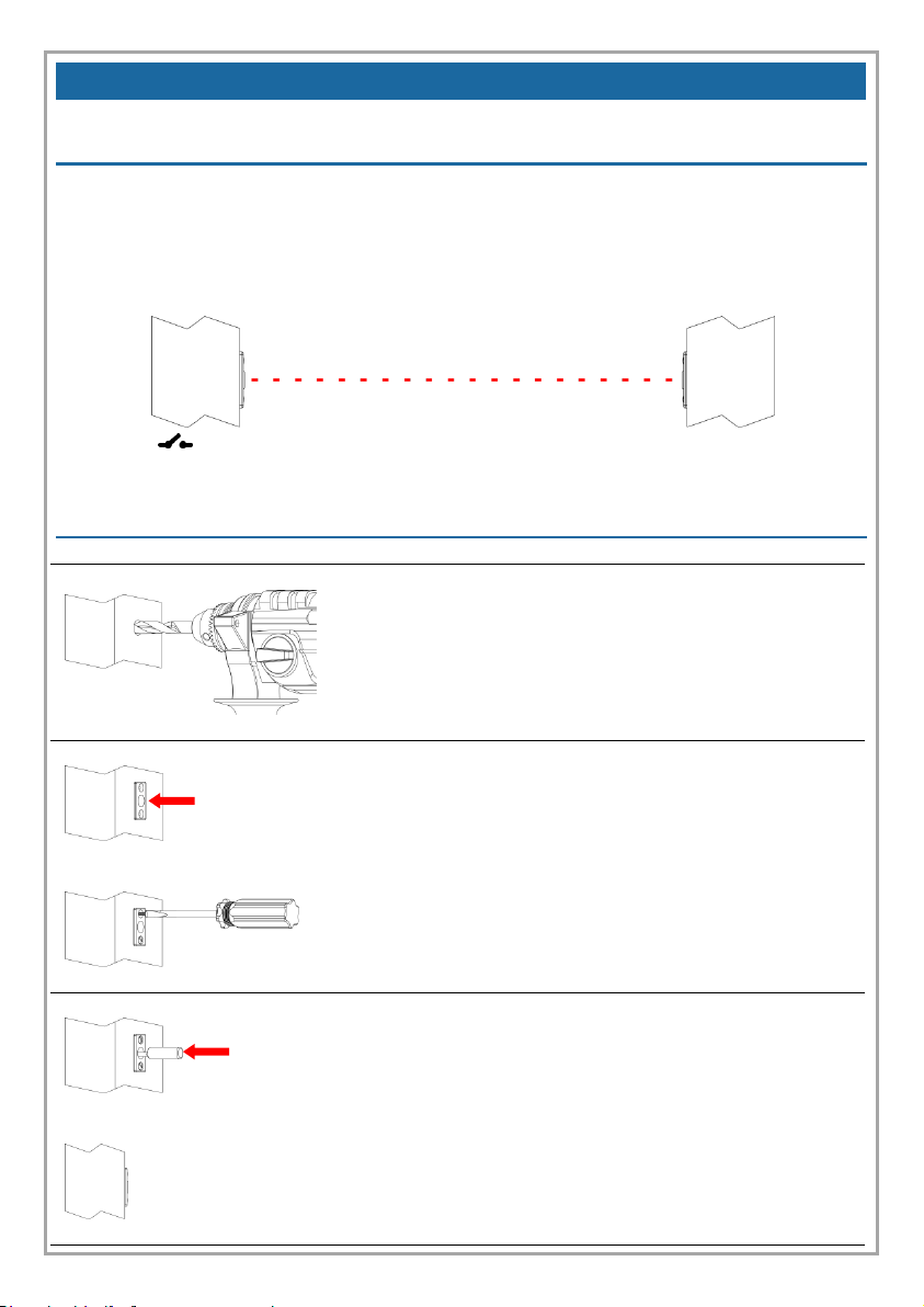
A L I G N M E N T A N D I N S T A L L A T ION
Drill a Ø13mm hole.
Install the photocell bracket and fasten
it bracket with two screws
Install the Photocell in the bracket so
that it is flush with the wall
Alignment of photocells
During installation make sure that the transmitter and receiver are horizontally
aligned as illustrated below. The photocells can work with a slight offset
(depending on the distance in-between) but this is not recommended as the
sensitivity is affected.
The LED - Relay State will flash green when signal is OK and red if not OK. The green led will
flash faster the more signal there is present.
Installation of photocells
Page 4
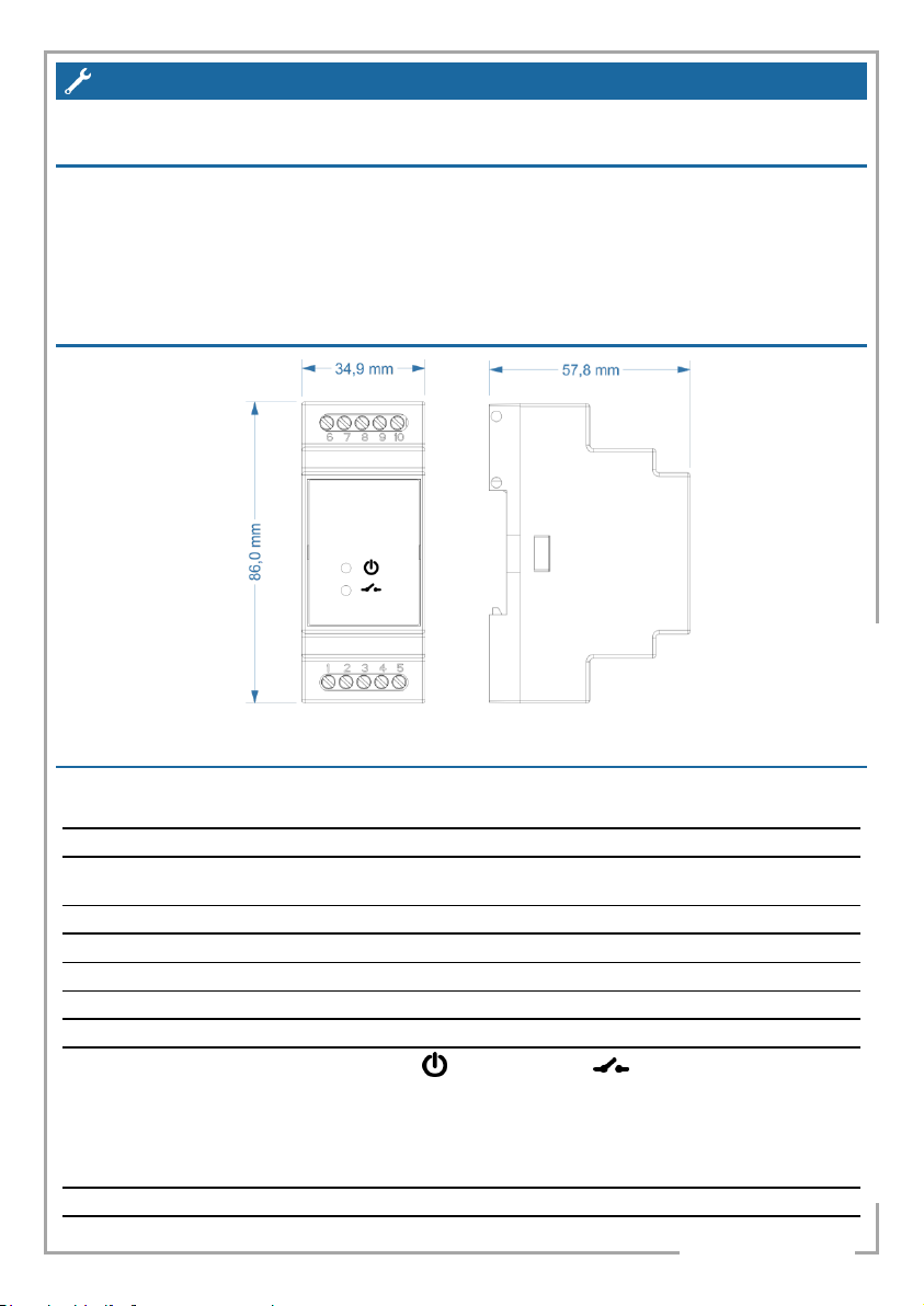
T E C H N I C A L D A T A
Supply Voltages, - see order no below.
Other voltages on order.
230VAC (+/- 10%), 110VAC, 24VAC or 24VDC.
Consumption
AC-versions 1.5 VA, DC versions max. 70 mA.
Sensing range with DOT T15 and R15 /
M15 sensors
0-15 m, automatic gain control.
Wiring
Terminal blocks.
Operation mode
Light activated, - see function below. Test input facility.
Output
Relay changeover contact rated 8A/250VAC.
Response time
25 ms
Switching frequency
Max. 10 Hz.
Indicators
- Status
- Relay State
Green = OK /
Red = Test active
Green = Beam not broken (N.O.)
Green Flashing = Signal Strength
Red = Beam broken (N.C.)
Red flash
Red flash = Connection Error
Operating temperature
-20 - +50ºC
Housing, dimensions and weight
Grey polycarbonate IP50, 35x86x58 mm
This product is designed and assembled by Speed Tech A/S in Denmark
11-10-2016 - V1.0.2 – REV. A
Troubleshooting:
In case the photocells does not work as intended during day check if the
receiver is exposed to direct sunlight.
If this is the case try swapping the transceiver and receiver.
Mechanical dimensions:
Technical data:
 Loading...