

Page 1

Nov 18, 2013
1967-1969 Camaro and 1968-74 Nova
Complete Sub Frame
Installation Instructions
The following instructions are intended for professional installers
and are guidelines only. Speedtech Performance assumes NO
responsibility for the installation of any of its products. All products are
intended for off road use only and must be installed by qualified
professionals only
Thank you for purchasing your new Speedtech Sub Frame suspension kit. Installing this
product will require the removal of your old sub frame, engine and transmission from the car.
Take all necessary precautions whenever jacking up your vehicle and use safe and sturdy jack
stands to support the vehicle whenever it is off the ground. Be sure to take all other safety
precautions required to do the job correctly.
1 | P a g e
Page 2

Sub Frame Hardware Kit Checklist
Sub Frame Instructions -1
Bolts
Upper shock mount (2)
½ x 1 ¾ Shoulder bolt
Motor mount frame pad (6)
7/16 x 3/4 NF
Transmission X member (4)
7/16 x 1 1/4 NF
Upper control arm mount (4)
7/16 x 2 1/4 NF
Sway bar mounting (4)
3/8 x 1 NF
Nylock Nuts
7/16 (8)
3/8 Large Flange (2)
Washers
7/16 (22)
3/8 (6)
Sway bar mounting hardware is included with the sway bar and the sway
bar end links are included with the High Clearance lower control arms.
2 | P a g e
Page 3

Assembling the Sub Frame
1. Support the sub frame with jack stands at each corner, be sure it is sturdy
and level.
2. Install the supplied motor mounts. Do not fully tighten the bolts at this time to
allow adjustment later when installing the engine.
Note: LS Series motors use 2 different length frame pads, the Taller Pad must be installed
on the Driver Side. This will move the motor over ¾” to clear the oil pan rail. You must also us
an LS motor mount adapter such as the ATS # 070001.
Small Block and Big Block engine stands are equal in height and can be installed on either
side.
3 | P a g e
Page 4

3. Install the transmission cross member. Do not fully tighten the bolts at this
time to allow adjustment later when installing the engine and transmission.
4. Install the lower control arms. Begin control arm installation by sliding the
frame end up into the frame pockets, the straight tube should be located to the
rear.
4 | P a g e
Page 5

Install only the ½” x 3 ½” front mounting bolt at this time. Apply anti-seize
lubricant to the shank of the bolts. The rear bolt will be installed later along with
the rack and pinion bracket.
5 | P a g e
Page 6
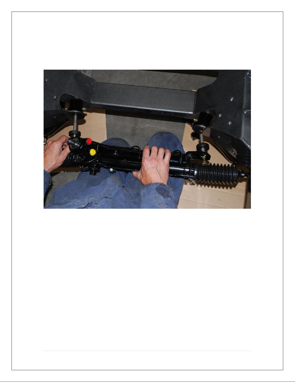
5. Remove Steering rack from packaging. You will not be using the long lower
control arm (LCA) mounting bolts that come with the rack hardware. Instead use
the Speedtech Grade 8, 4 1/2” long mounting bolts supplied with the control
arms.
You must remove the rack from the mounting bracket to get the driver side bolt
into it's position in the bracket. Apply anti-seize lubricant to the shank of the bolts,
install into bracket, then reinstall bracket onto rack body.
For proper alignment, refer to the installation instructions included with the rack
and pinion. The 2 mounting bolts must go in at the same time (see photo above)
and the bracket and spacers must end up flush against the frame. It may take 2
people to perform this procedure, it is a tight fit.
6 | P a g e
Page 7

The lock nuts that are provided with the lower control arms must be installed
through the hole in the bottom of the sub frame, a small amount of red Loctite is
suggested. At this time you can torque all 4 lower control arm nuts to 70 ft/ lbs.
It is recommended you grease the LCA bushings via the grease fittings at this
time. We suggest using Permatex Ultra Slick Synthetic Grease but any high
quality chassis grease will do.
7 | P a g e
Page 8

6. Assemble the coilover shocks. Start by installing the adjusting nuts threaded to
the extreme bottom of the shock.
Install the adjusting thrust bearings and washers on top of the nuts prior to the
spring.
Install spring and spring cap. The spring may need to be compressed in order to
get the cap on correctly.
Install the supplied T-bar into the bottom bushing of the shock and install the
snap rings.
8 | P a g e
Page 9

7. Install the lower side of the shock into the lower control arm. You have the
option to install the T bar on either the top or the bottom of the mounting pad.
Installing it on the bottom will lower the car approximately an additional 1 ¼”.
Install the top shock eyelet into the frame bracket. Tighten bolts to 20 ft/lbs.
9 | P a g e
Page 10

8. Install the Upper Control Arm (UCA) bolts into the slotted mounting holes. The
arm's stainless cross shaft mounts on the inside of the control arm mount
bracket, and the short straight tube on the arm should be towards the rear. These
holes in the frame are slotted to allow adjustment of the suspension's camber
curve. We recommend starting initially with the arms all the way up in the slot.
Tighten these bolts as needed and the alignment shop will torque them to specs.
10 | P a g e
Page 11

9. Factory spindles can be reinstalled. For optimum performance we recommend
using ATS AFX tall spindles. Tighten the lower ball joint to 60 ft/lbs and install the
cotter pin. Tighten the upper ball joint to 40 ft/lbs. and install the cotter pin.
10. Install the new steering arms using either your original hardware or new
grade 8 hardware. Install the outer tie rod ends into the steering arms, torque to
rack and pinion manufacturer specs.
11 | P a g e
Page 12

Speedtech Sway Bar Install
11. Installation of the sway bar is
basically the same as any standard
sway bar. T polyurethane pivot
bushings/ mounting hardware are
included in the sway bar package. The
end link hardware is included with the
High Clearance lower control arms.
Mount the bar to the sub frame first,
bolting the pivot bushing brackets to
the vertical pads welded to the front
cross member. Then install the end
links with the supplied 3/8 hardware,
inserting the bolt through the washer,
poly bushing, sway bar, poly bushing,
and washer. Now add the 3/8 Jam nut,
then thread it into the rod end.
That completes the assembly of the sub frame. You now have the choice to
either install the sub frame into the car or continue to install the motor and
transmission into the sub frame, then install the entire assembly into the car.
12 | P a g e
Page 13

12. Before any removal of the old sub frame begins, disconnect and remove the
battery, but you knew that.
13. Mark all hoses, lines and cables that pertain to engine, transmission and sub
frame removal and disconnect and/ or remove them.
13 | P a g e
Page 14

14. Once you have removed your original sub frame there are a couple of ways to
proceed. If you are using a two post hoist, we recommend you install the motor
and transmission into the Speedtech sub frame and then install the completed unit
into the car. This allows more room to perform some detail work on the entire
assembly without the car's front clip in the way.
Engine Install
15. When installing your engine you must use Energy Suspension mount # 3.1114
and transmission mount # 3.1108 or equivalent. You must also us an LS motor
mount adapter plate, we recommend the ATS # 070001
Small Block and Big Block Chevrolet engines should fit the sub frame with a stock
style oil pan. Factory LS oil pans will have clearance issues and will not work. We
recommend the internally baffled ATS #70003 road race pan for standard LS
motors and the ATS #70004 for LS7 and LS9 dry sump systems.
If you are using the original clutch “Z” bar, Speedtech offers a bracket available
that is installed on the front of the driver side mid body mount. Please specify
what clutch you are using when ordering.
Reminder: LS Series motors use 2 different length frame stands. The longer of the 2 MUST be
installed on the driver side! This will move the motor over ¾” to clear the oil pan rail. Small
Block and Big Block stands are the same height.
14 | P a g e
Page 15

Speedtech offers two types of LSx oil pans for use with our sub frames. Pictured
above is the ATS # 70003 LSx Road Race oil pan. It features internal baffling,
trap doors and a windage tray. It also features bungs and fittings for remote oil
filter mount, oil pressure and temp gauges, and turbo oil line. Pictured below is
the ATS # 70004 LS7 and LS9 dry sump oil pans. These pans feature internal
passages that maintain the use of a dry sump style oiling system. It also features
fittings for remote oil filter and cooler lines.
15 | P a g e
Page 16

If you have not already purchased headers, Speedtech has developed headers
specifically for our sub frame that fit Chevrolet LSx, small block and big block
series engines. These headers allow the use of a 2 joint rather than a 3 joint
steering shaft which improves the responsiveness and overall feel of the steering
system. They are also designed to optimize ground clearance for lowered
vehicles.
16. Your steering shaft connection will need to be assembled and installed. If you
have not already purchased a steering shaft kit, Speedtech offers several
different configurations depending on what steering column and headers you are
using.
16 | P a g e
Page 17

Note: It is imperative when setting up and installing the steering shaft that
the shaft does not protrude beyond the end of the u-joint housing. Damage
and binding will occur if this is not installed properly.
The steering shaft is typically left long to allow for trimming. Mock up the shaft
assembly in place and trim as needed to ensure that the correct length is
achieved.
When installing the shaft you MUST offset the u-joints by approximately 45
degrees. You will find one end is splined to allow the shaft to be rotated and
“phased” to eliminate any binding. You may have to adjust the phasing slightly
from this 45 degree starting position to completely eliminate any binding.
17 | P a g e
Page 18

17. The sub frame has alignment holes located in the mid body mounts to
facilitate alignment of the sub frame once it is installed in the car, see position 1
in the figure below. Use a long alignment punch to move the sub assembly
around and square and align to the body. You must square and align the sub
frame in the equalizing the measurements on line “F” and then on line “G”.
Squaring it this way using both the front to back (G) and diagonal (F) methods
will endure the best possible frame to body alignment.
18. Once you have the frame squared and all body mount bolts tightened to 140
ft/lbs, reinstall and reconnect all accessories as they were before.
Do not drive the car until it has had a proper
suspension alignment.
Once you have completed the sub frame install, have the vehicle towed to a
competent professional alignment shop to have the alignment performed.
Note: Use alignment specifications on next page, not alignment shop
pre-programmed factory specs!
18 | P a g e
Page 19

Driver Side
Passenger Side
4 Degrees positive Caster
4 ½ Degrees positive Caster
0 to ½ Degree negative Camber
0 to ½ Degree negative Camber
3/ 32 Total Toe-in
3/ 32 Total Toe-in
Driver Side
Passenger Side
5 ½ Degrees positive Caster
6 Degrees positive Caster
½ to 1 Degree negative Camber
½ to 1 Degree negative Camber
3/ 32 Total Toe-in
3/ 32 Total Toe-in
Driver Side
Passenger Side
½ Degree positive Caster
½ Degree positive Caster
¼ to ½ Degree negative Camber
¼ to ½ Degree negative Camber
1/8 Total Toe-in
1/8 Total Toe-in
Alignment Specifications 67-69 Camaro 68-74 Nova
Note: These are only suggestions and may need additional changes to
achieve the optimum settings for your driving style or situation.
Daily Driving, Street Performance Specifications
Aggressive Track Alignment Specifications
Original Alignment Specifications
**For reference purposes only. Do Not use these specs.
Speedtech Performance USA LLC
3884 S. River Rd. Bldg A
St. George, UT 84790
(435)-628-4300
www.speedtechperformance.com
19 | P a g e
Page 20

Terms and Conditions of Sale
1. Effective January, 2008, supersedes all previous policy statements. Policies are subject to change without notice. Speed tech performance
Ltd. is not responsible for printing errors.
2. Speed Tech Performance Ltd. does not endorse, nor recommend modification of vehicles for use on public highways, since warranty or
government regulations may be violated. As an express condition of sale of any performance part, the buyer acknowledges and agrees to use
the performance parts for the modification of vehicles in sanctioned OFF-ROAD competitive events and show purposes only. Customers
should exercise their discretion on matters with regards to the purchase and installation of these products.
3. Speed Tech Performance Ltd. does not ensure the legal use of these products. We do not guarantee the fitment of these products for
anything other than there intended application nor do we assume any responsibilities what so ever for the misuse or losses incurred by the
use of any of these components. While every effort is made to provide technical information and assistance, we have no control over owner
installation, modification, and unusual stress that performance parts are subject to.
4. The customer acknowledges that Speed Tech Performance Ltd. and its employees are not responsible for any mechanical failures due to
the use of parts sold, supplied or installed not for their intended application. Speed Tech Performance Ltd will not be held liable for any
damages which are incurred directly or indirectly on the vehicles or operators or passengers of the vehicle
5. Please consult your sales agent and/or technician prior to purchase of any of Speed Tech Performance Ltd. Products to ensure proper fit.
The buyer assumes all responsibilities for determining the suitability of the product. All aftermarket products should always be installed by
professionals only.
Warranty Claim:
1. Speed tech Performance Ltd. Warrants its products against materials and workmanship failure for the term of 12 months (1 year) from the
date of purchase and only up to the amount paid with proof of purchase.
2. Seller’s liability shall as limited to repairing or replacing, at its option, any defective product which is returned, freight prepaid to Seller,
according to the Merchandise Return Procedure set forth in Section 3 below. Buyer shall bear all responsibility for shipping charges and risk of
loss or damage during transit to Seller. Products which have been subjected to abuse, misuse, alteration, neglect or unauthorized repair or
installation, as determined solely by Seller, are not covered by this warranty. Any alterations, addition, improvements or attachments to the
product(s) not authorized in writing by the Seller shall be deemed to be a waiver of this warranty by Buyer and shall render this warranty null
and void. Seller shall return repaired or replaced product(s) to Buyer, at its expense via regular ground service in Canada. Shipping charges
by all other methods and to all other destinations shall be borne by Buyer.
3. Merchandise return procedure
A. If you purchased your Speed tech performance ltd product from us or from an authorized dealer, you are covered by the terms of this policy.
All claims however, must be submitted directly to Speed tech performance Ltd.
B. Call the customer service representative at 1-888-467-1625.
C. Provide the invoice number, date of purchase and reason for return
D. You will be assigned a Returned Goods Authorization Number (RGA). The package you return must show the RGA on the outside of the
package, include the original invoice and be shipped prepaid to our facility. The part has to be in its original packaging materials and be in a
sellable condition. For parts presenting signs of use, only warranty claims will be accepted.
E. Ship to seller, freight pre-paid and insured for replacement cost in original packaging.
F. Replacement or repair decision will be made when merchandise is received by seller. No advance replacement is available.
How to File a Warranty Claim:
The answer to ALL the following questions should be YES before contacting our Customer Service Department.
Is the part appropriate to your application?
Did you carefully and thoroughly read the instructions provided along with the part?
Do you have the proof of purchase?
Are you the original purchaser?
Is the part unmodified and clean?
Is the return date within 3 months from the purchase date?
Is the reason for return a legitimate product defect?
If the answer to all these questions is YES, please contact our Customer Service Department at 1-888-467-1625. You will be given a Returned
Goods Authorization Number (RGA) valid for 30 days. You will also be asked to ship the part prepaid to our facility. All shipments MUST be
prepaid, include the original invoice and show the RGA on the outside of the package, otherwise it will be refused. Please include a brief
explanation letter in order to expedite the warranty analysis process.
What doesn’t this Warranty Cover?
The costs not covered by this warranty include but are not limited to:
- Removal, installation, shipment and insurance costs.
- Improper installation or maintenance
- Misuse or abuse, negligence
- Damage to related components
- Normal wear and tear.
- Costs incurred due to down time of vehicle
- Alterations on the original design or unauthorized repairs.
All warranties implied by law are limited in duration of this warranty. You have specific rights that may vary from state to state or Province to
Province. By purchasing any of the products that are manufactured by speed tech performance you agree to any and all of the above terms
and conditions. Copyright © Speedtech Performance USA LLC
20 | P a g e
 Loading...