

Page 1
February 3, 2014
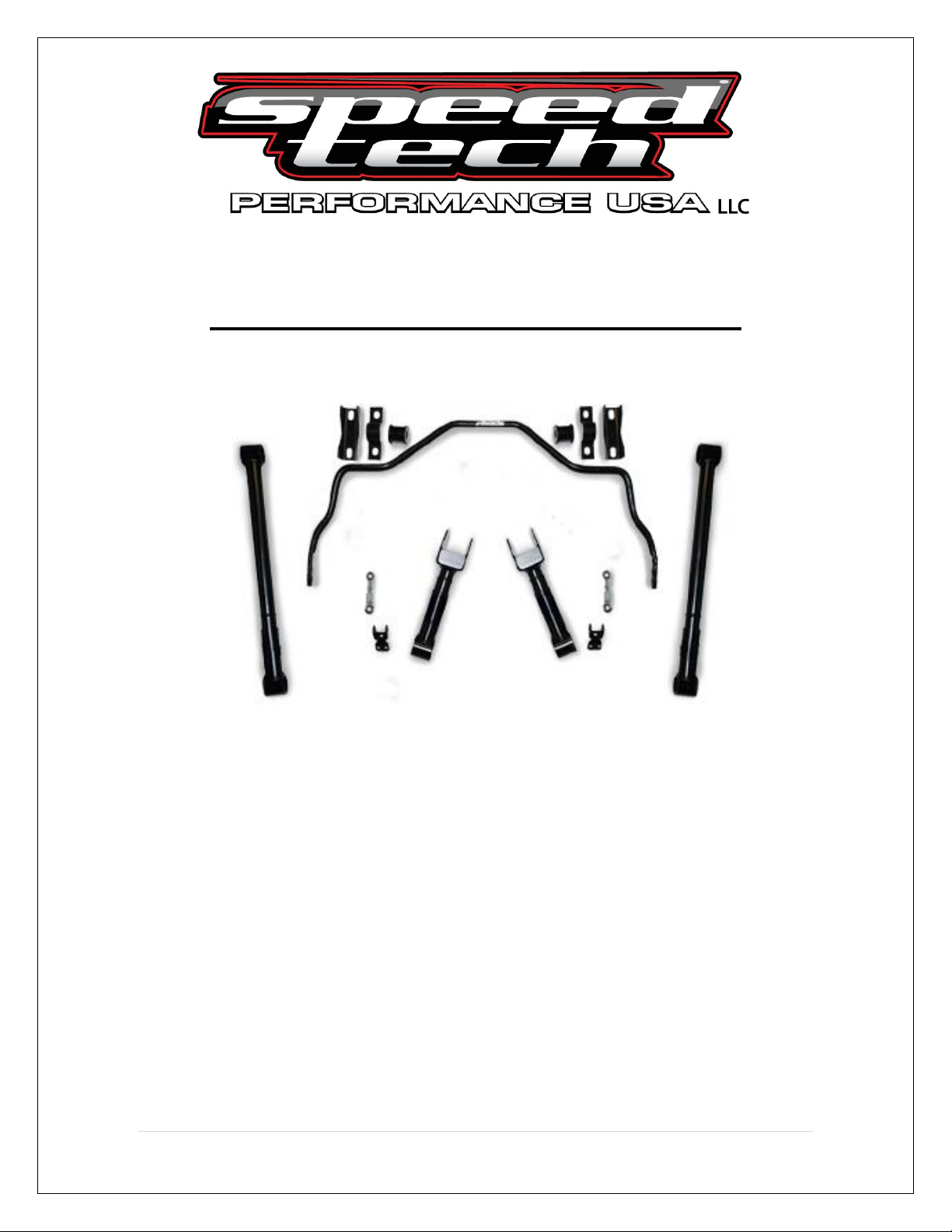
'64-72 Chevelle/ A Body Rear Trailing Arm Kit
The following instructions are intended for professional installers
and are guidelines only. Speedtech Performance assumes NO
responsibility for the installation of any of its products. All products are
intended for off road use only and must be installed by qualified
professionals only.
Thank you for purchasing your new Speedtech A Body Trailing arm kit. Installing this product
will require the unbolting and removal of your rear suspension. Take all necessary precautions
whenever jacking up your vehicle and use safe and sturdy jack stands to support the vehicle
whenever it is off the ground. Be sure to take all other safety precautions required to do the job
correctly.
1 | P a g e
Page 2

A Body Rear Trailing Arm Hardware Kit Checklist
Installation Instructions (1)
Articulink Upper Trailing Arm (2)
Articulink Lower Trailing Arm (2)
Sway Bar End Link Assemblies (2)
Sway Bar End Link Brackets (2)
Trailing Arms
½ x 3 ½ “ Bolts (8)
½” Stover Lock Nut (8)
½ ” dia. Bolt Sleeves (6)
Sway Bar Links
3/8 x 2” Fine Bolts (4)
3/8” Fine Nylock Nuts (4)
3/8” Washers (4)
Sway Bar Link Brackets
3/8 x 3/4” Coarse Bolts (16)
3/8” Coarse Nylock Nuts (4)
3/8” Washers (8)
*Additionally you will need a drill with a 3/8” bit to properly mount the
sway bar end link brackets.
The vehicle should be on a level surface before you start.
2 | P a g e
Page 3

1. In a couple short hours you can update your Chevelle with new Speedtech
Performance trailing arms. We recommend you inspect all of your car's
suspension components prior to installation of our parts, such as bushings and
brake lines which may be worn and could cause adverse effects. Replace parts
as necessary. Axle mounted rubber upper trailing arm bushings are Moog
#K5161.
2. Jack up and properly support the vehicle on sturdy jack stands, two supporting
the rear axle and two supporting the front of the frame. Remove the rear wheels.
With the rear axle supported, record pinion angle AT RIDE HEIGHT. You will
need to match this number after your new trailing arms are installed. An easy
way to do this is attach your pinion gauge to the heads of two rear end cover
bolts that align vertically.
3. Support the rear of the frame with jack stands. Remove the shocks and
watching that you don't stretch the brake hose, carefully lower the rear axle until
you can remove the coil springs. Support the axle with jack stands. Place
another jack stand under the pinion ujoint to keep the rear axle from rotating
once it is unbolted. Remove the upper trailing arms.
4. Using the factory upper arms, line up the bolt holes with those on the
Speedtech upper arms. If an adjustment is needed, the Speedtech Articulink
control arms are threaded and can be adjusted by twisting them either to the
right to shorten or left to lengthen. See diagram on page 4.
3 | P a g e
Page 4

5. Using the new bolts install the Speedtech upper trailing arms with the grease
fitting pointing downward.
4 | P a g e
Page 5

5. Remove the factory lower trailing arms. Adjust the Speedtech lowers as
needed in the same manner as the uppers. Install the trailing arms with the new
bolts. Raise the axle to ride height and recheck pinion angle. If the angle is off,
remove the rearward end of the lower trailing arms. Adjust the driver's side arm
and reinstall. Adjust passenger arm to match bolt hole alignment and reinstall.
Check pinion angle again. Repeat process until desired pinion angle is achieved.
6. Check to make sure the rear axle is laterally centered side to side in the car
and the wheels are centered front to back in the wheel opening. Adjust trailing
arms as needed. Always be sure pinion angle is rechecked as centering
adjustments are made.
7. Reinstall coil springs and shocks.
5 | P a g e
Page 6

Sway Bar Installation
1. Use the sway bar hardware to attach bar to the rear axle. Do not fully tighten
at this time. See sway bar instructions for further information.
2. You will not be using the end links and associated hardware that come with
the sway bar. Bolt the end links that come with the trailing arms to the sway bar
on the inside of the bar, with the spacer between the link and the sway bar. Do
not fully tighten yet. Attach the upper link brackets to the links and position with
the vertical tab against the front of the frame cross member. Be sure the links are
standing vertically. Mark two holes to bolt down each of the brackets, one for the
horizontal hole and one for a vertical hole. Remove the bracket from the links
and drill the holes with the 3/8” bit. Bolt down the brackets, then bolt the links to
the brackets.
6 | P a g e
Page 7

7. Be sure all bolts are tight.
Speedtech Performance USA LLC
435-628-4300
www.speedtechperformance.com
Copyright Speedtech Performance USA, LLC 2014
7 | P a g e
Page 8

Terms and Conditions of Sale
1. Effective January, 2008, supersedes all previous policy statements. Policies are subject to change without notice. Speed tech performance
Ltd. is not responsible for printing errors.
2. Speed Tech Performance Ltd. does not endorse, nor recommend modification of vehicles for use on public highways, since warranty or
government regulations may be violated. As an express condition of sale of any performance part, the buyer acknowledges and agrees to use
the performance parts for the modification of vehicles in sanctioned OFF-ROAD competitive events and show purposes only. Customers
should exercise their discretion on matters with regards to the purchase and installation of these products.
3. Speed Tech Performance Ltd. does not ensure the legal use of these products. We do not guarantee the fitment of these products for
anything other than there intended application nor do we assume any responsibilities what so ever for the misuse or losses incurred by the
use of any of these components. While every effort is made to provide technical information and assistance, we have no control over owner
installation, modification, and unusual stress that performance parts are subject to.
4. The customer acknowledges that Speed Tech Performance Ltd. and its employees are not responsible for any mechanical failures due to
the use of parts sold, supplied or installed not for their intended application. Speed Tech Performance Ltd will not be held liable for any
damages which are incurred directly or indirectly on the vehicles or operators or passengers of the vehicle
5. Please consult your sales agent and/or technician prior to purchase of any of Speed Tech Performance Ltd. Products to ensure proper fit.
The buyer assumes all responsibilities for determining the suitability of the product. All aftermarket products should always be installed by
professionals only.
Warranty Claim:
1. Speed tech Performance Ltd. Warrants its products against materials and workmanship failure for the term of 12 months (1 year) from the
date of purchase and only up to the amount paid with proof of purchase.
2. Seller’s liability shall as limited to repairing or replacing, at its option, any defective product which is returned, freight prepaid to Seller,
according to the Merchandise Return Procedure set forth in Section 3 below. Buyer shall bear all responsibility for shipping charges and risk of
loss or damage during transit to Seller. Products which have been subjected to abuse, misuse, alteration, neglect or unauthorized repair or
installation, as determined solely by Seller, are not covered by this warranty. Any alterations, addition, improvements or attachments to the
product(s) not authorized in writing by the Seller shall be deemed to be a waiver of this warranty by Buyer and shall render this warranty null
and void. Seller shall return repaired or replaced product(s) to Buyer, at its expense via regular ground service in Canada. Shipping charges
by all other methods and to all other destinations shall be borne by Buyer.
3. Merchandise return procedure
A. If you purchased your Speed tech performance ltd product from us or from an authorized dealer, you are covered by the terms of this policy.
All claims however, must be submitted directly to Speed tech performance Ltd.
B. Call the customer service representative at 1-888-467-1625.
C. Provide the invoice number, date of purchase and reason for return
D. You will be assigned a Returned Goods Authorization Number (RGA). The package you return must show the RGA on the outside of the
package, include the original invoice and be shipped prepaid to our facility. The part has to be in its original packaging materials and be in a
resellable condition. For parts presenting signs of use, only warranty claims will be accepted.
E. Ship to seller, freight pre-paid and insured for replacement cost in original packaging.
F. Replacement or repair decision will be made when merchandise is received by seller. No advance replacement is available.
How to File a Warranty Claim:
The answer to ALL the following questions should be YES before contacting our Customer Service Department.
Is the part appropriate to your application?
Did you carefully and thoroughly read the instructions provided along with the part?
Do you have the proof of purchase?
Are you the original purchaser?
Is the part unmodified and clean?
Is the return date within 3 months from the purchase date?
Is the reason for return a legitimate product defect?
If the answer to all these questions is YES, please contact our Customer Service Department at 1-888-467-1625. You will be given a Returned
Goods Authorization Number (RGA) valid for 30 days. You will also be asked to ship the part prepaid to our facility. All shipments MUST be
prepaid, include the original invoice and show the RGA on the outside of the package, otherwise it will be refused. Please include a brief
explanation letter in order to expedite the warranty analysis process.
What doesn’t this Warranty Cover?
The costs not covered by this warranty include but are not limited to:
- Removal, installation, shipment and insurance costs.
- Improper installation or maintenance
- Misuse or abuse, negligence
- Damage to related components
- Normal wear and tear.
- Costs incurred due to down time of vehicle
- Alterations on the original design or unauthorized repairs.
All warranties implied by law are limited in duration of this warranty. You have specific rights that may vary from state to state or Province to
Province. By purchasing any of the products that are manufactured by speed tech performance you agree to any and all of the above terms
and conditions. Copyright © Speedtech Performance USA LLC
8 | P a g e
 Loading...