

Speed Queen SLW330RAW, PSLW330RAW Technical Information
Speed Queen R Domestic WasherTechnical Information
!
!
120 V, 60 Hz Models
SLW330RAW PSLW330RAW
• Due to possibility of personal injury or property damage, always contact an authorized technician for servicing or
repair of this unit.
• Refer to Service Manual RS3100007 for detailed installation, operating, testing, troubleshooting, and disassembly
instructions.
• Refer to Parts Manual RP3100017 for part number information.
CAUTION
All safety information must be followed as provided in this Technical Sheet and in Service Manual RS3100007.
WARNING
To avoid risk of electrical shock, personal injury, or death, disconnect power to unit and discharge capacitor
before servicing, unless testing requires it.
Models SLW330RAW Models SLW330RAW
Power Source Wash cyles
Voltage AC 120 VAC
Amperage (Single Unit) 10 A
Frequency 60 Hz
Motor horsepower 1/2
Receptacle 6-20R Self-cleaning lint filter X
Plug 6-20P Self-adjusting rear leveling legs X
Dimensions
Cabinet
Height−overall
Height of cabinet 36”
Width 27”
Depth 28” Spin speed (revolutions per minute) 640 / 427 rpm
Clearance−washer lid
Weight
Crated 193 lbs. Medium 46 spm
43” Fabric softener dispenser X
17 1/2”
Water temperatures
Water level
Features
Steady Spin Balance Sy stem
210 Agitation stroke X
Tri−Action wash system
Motor speed
Agitation speed
High 69 spm
(strokes per minute)
Variable
2 speed
7
3
X
X
August 2000 RT3100014 Rev. 01
Component Testing Information
!
WARNING
To avoid risk of electrical shock, personal injury, or death, disconnect power to washer before servicing, unless
testing requires it.
Illustration Component Test Procedure Results
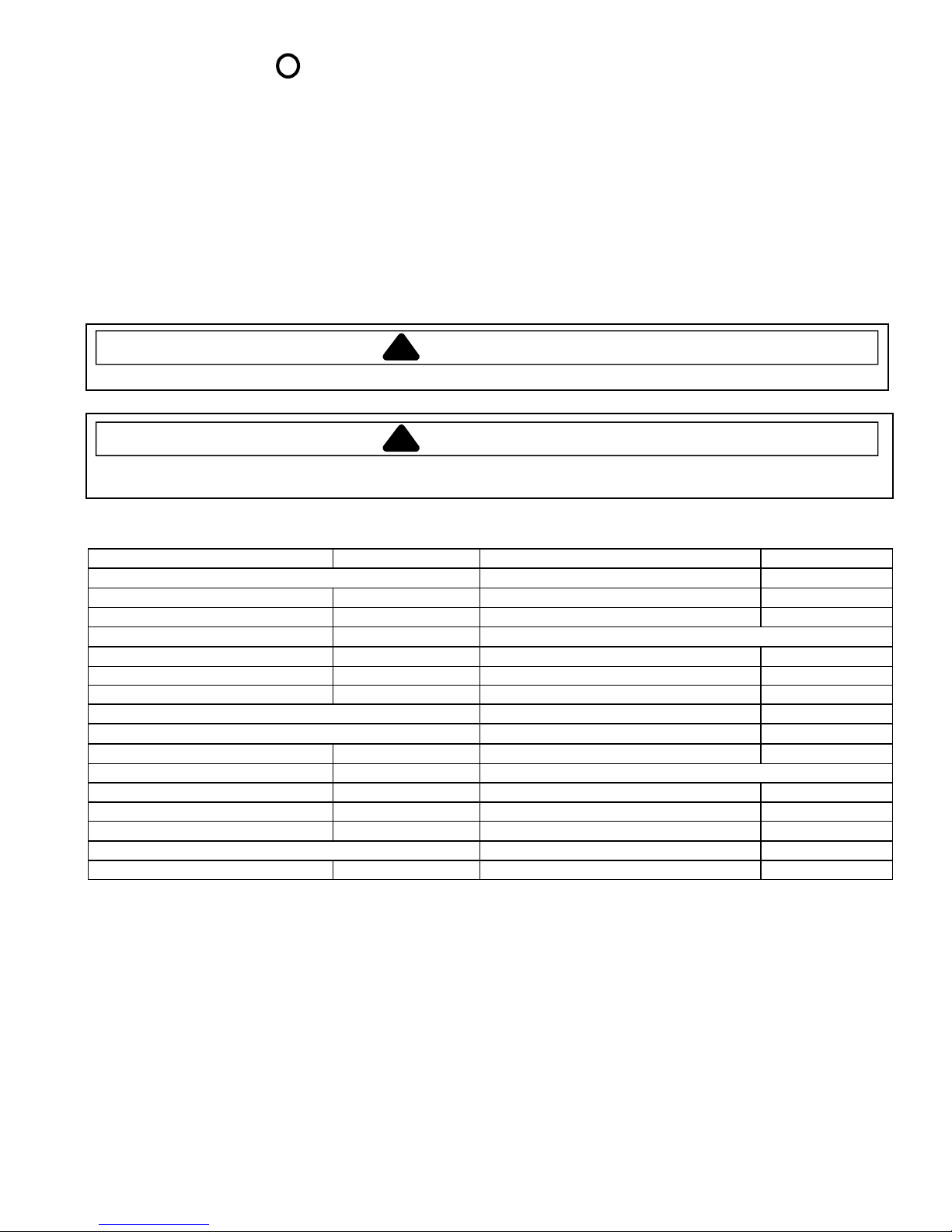
40077101
1
2
3
A
L1
4
L2
Temperature switc h
3
4
B
L1 = A
L2 = B
3 = 1, 2
4 = 3, 4
Disconnect wires from component to
properly measure the resistance of t he
component.
Place switch in the following positions
and measure across the terminals
below:
Hot / Cold L1-4
Warm / Cold L1-3, L1-4, 3-4 Cold / Cold L1-3
>1
>1
>1
Ω
Ω
Ω
40097701 Mixing valve Measure resistance of terminals on
40058801 Timer Verify input and out put voltage is
40077201
40035001
2
1
3
Pressure swi tch Do not disconnect the pressure hose
Lid switch−SPST
each valve.
Resistance across each valve.
present.
Verify wiring is correctly connec ted to
the timer.
from pressure switch to perform
measurements.
Measure resistance across t he
following termi nals on the pressure
switch:
Terminal 1 to 2
Terminal 1 to 3
Disconnect wire terminals from s witch.
Test terminals with switch closed.
Test terminals with switch open.
Approximately 1000 Ω ± 10%
See timing sequence chart for functi onal
description of the component.
Refer to wiring diagram/schematic for
correct contacts.
Air pressure that actuates swit ch is
determined by the water level of the
tub.
Continuity (no pres sure)
Continuity (pres sure)
Continuity >1
Infinite 1 M
Ω
Ω
R0000014 Brake pad kit If washtub does not stop spinning
RT3100014 Rev. 0 August 20002
within seven seconds after opening
loading door.
If brake pads make noises.
Replace all three br ake pads.
Apply a thin layer of silicone (26594P)
on pads, see Service Bulletin
“ASQ−213−B”
Component Testing Information
!
WARNING
To avoid risk of electrical shock, personal injury, or death, disconnect power to washer before servicing, unless
testing requires it.
Illustration Component Test Procedure Results
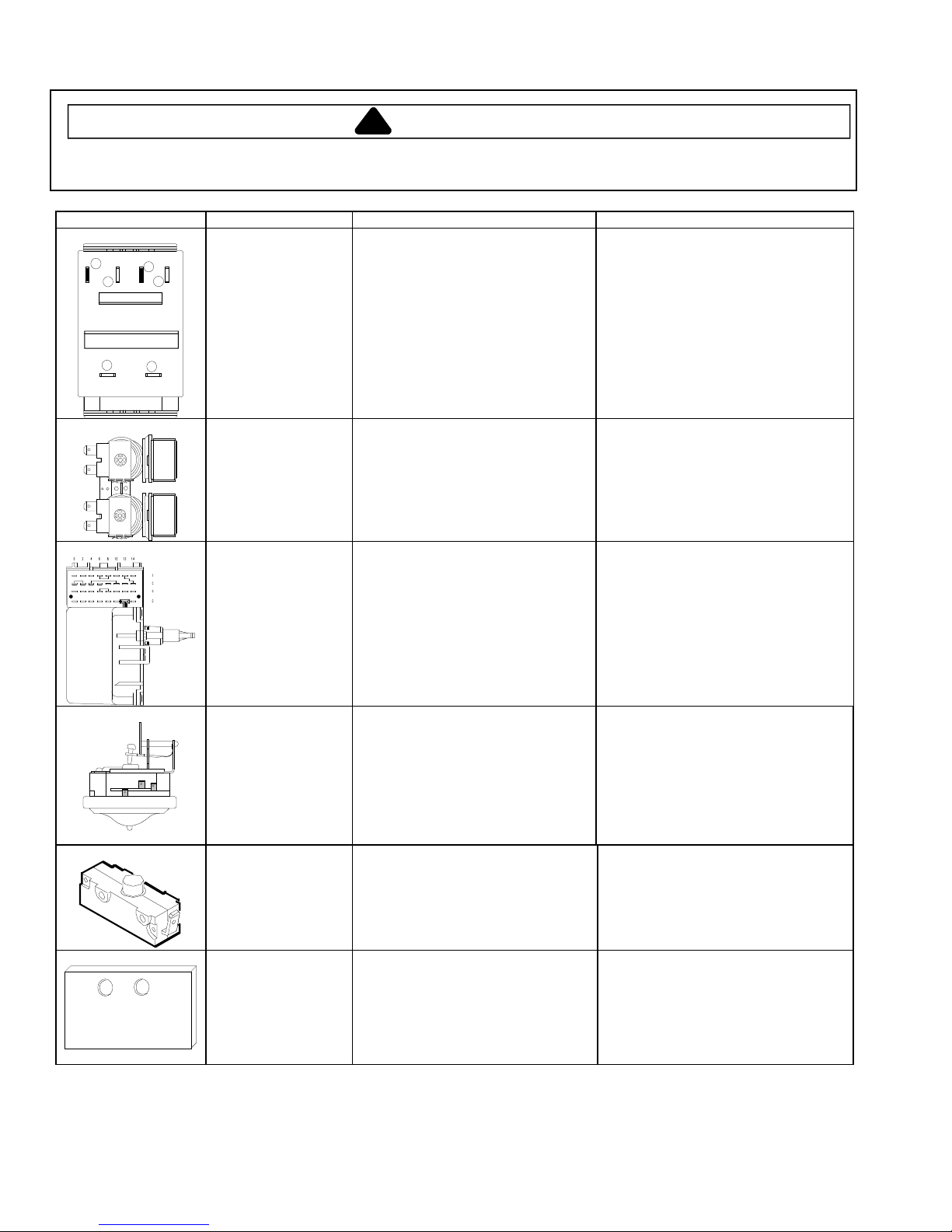
40095001 Motor Type of motor:
Two speed
See following section “Internal Motor
Diagram and Schematic” for correct
wiring contacts.
40040301 Drain pump Veri fy drain pump is not clogged or
40065301 Transmission
assembly
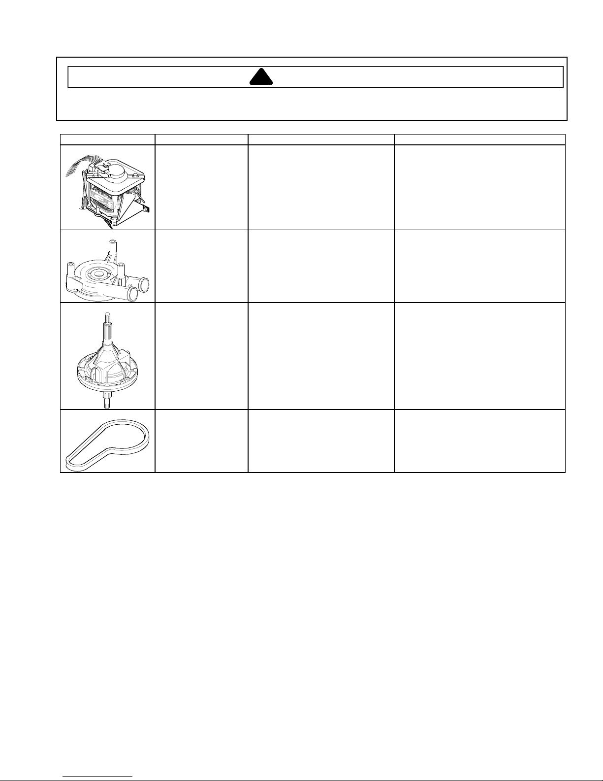
40053602 Drive belt Type of drive belt:
damaged.
Type of transmiss ion:
640 rpm
640 rpm
Refer to “Parts Manual” for proper
pulley size.
Remove clog and verify proper operation.
Replace drain pump if damaged.
Externally identical, must be identified by
part number.
If transmission locks-up, replace.
Refer to “Parts Manual”, to verify whic h
drive belt and pulley size is required.
August 2000 3 RT3100014 Rev. 0
 Loading...