

Page 1
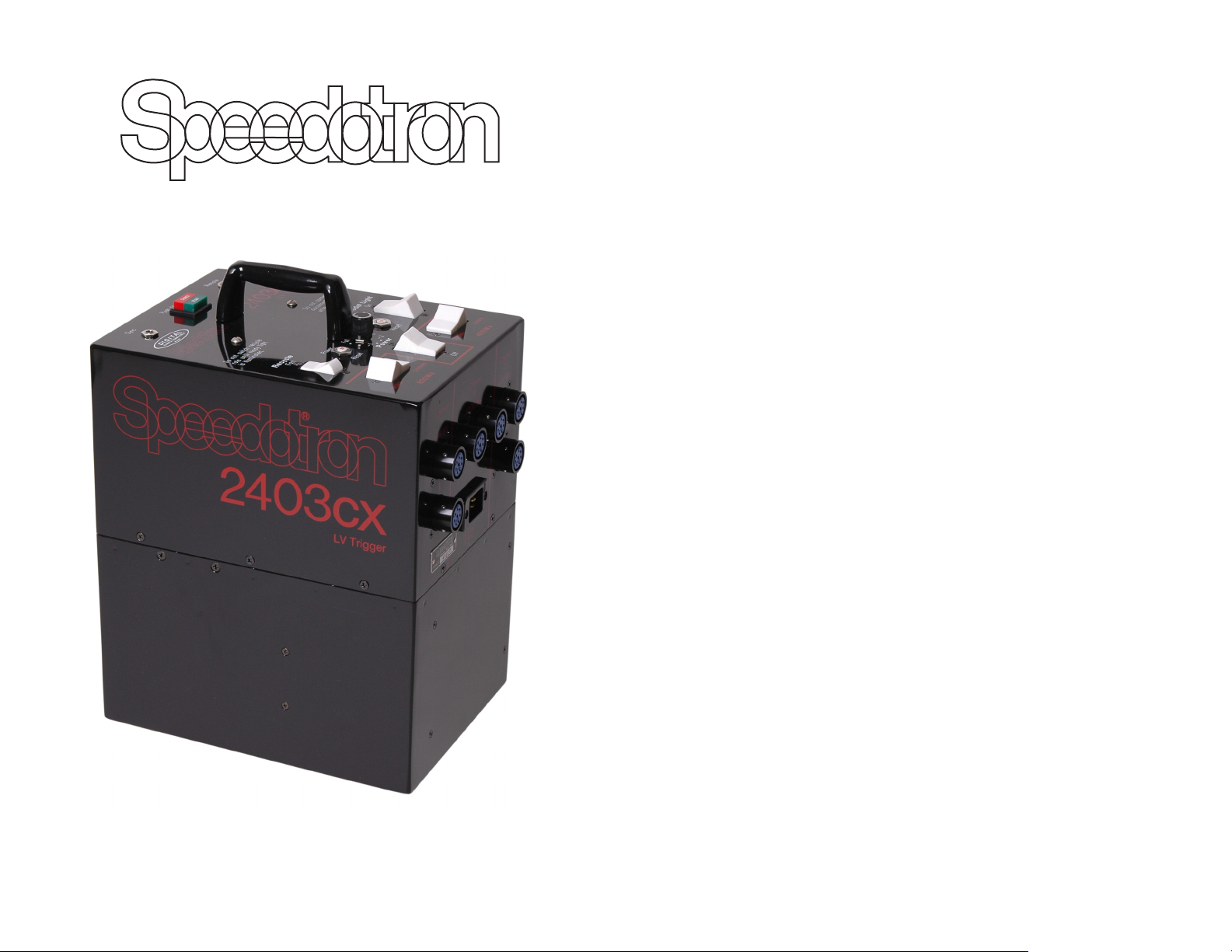
Welcome to Speedotron
Thank you for purchasing Speedotron Black Line equipment.
The name Speedotron is synonymous with professional
workmanship and the finest electronic flash equipment available.
Backed by years of experience, our engineers have developed
the Black Line system to take the rigors of daily professional use
with consistently outstanding results.
For more than 60 years, Speedotron’s reputation has grown
without much fanfare or advertising. Over the years, we have
found that a satisfied user is our best salesman. We are
determined to serve you well and offer the most efficient,
competent and courteous service anywhere.
If this is your first Speedotron purchase, this guide will help
you get the most out of your new equipment. If you've
purchased and used our equipment before, much of this
information will be familiar. In either case, we advise going over
this manual thoroughly. It contains vital information on the care
and proper use of all (including the latest) Speedotron products.
This manual is not a photographic handbook; only information
pertinent to basic operation is given. If you have questions about
how to handle a particular lighting situation or other application
that is not discussed, please contact us and we’ll answer your
questions as best we can.
The equipment you have purchased is heavy-duty, durable
equipment that will stand up to continuous use either on
location or in the studio. However, there are certain operating
procedures that should be adhered to insure maximum
performance. Treated with a reasonable care, your Black Line
system will provide you with dependable, consistent, long
lasting service.
Please help us to get to know you and fulfill our obligations
to you. Return the enclosed warranty registration card (found in
the center of this manual) to us immediately. Sending in this
card will validate your warranty and put your name on our
mailing list.
Instruction Manual
Speedotron Corporation
310 South Racine Avenue
Chicago, Illinois 60607
312/421-4050 - FAX: 312/421-5079
[email protected]
www.speedotron.com
welcome
Page 2

Speedotron’s 2-Year U.S. Limited Warranty
peedotron guarantees to repair or replace, free of charge, any part or parts found by factory
S
nspection to be defective due to faulty material or workmanship, provided the equipment is
i
returned to our factory prepaid. The period of warranty is two years from the date of original
urchase, except for flash tubes and modeling lamps, which are covered by the manufacturers’
p
warranties, not by Speedotron. Flash tubes, are covered for a period of one year only, and the
length of manufacturer’s warranties on modeling lamps varies.The Speedotron two-year
warranty does not apply to equipment which has been abused, cracked or broken in shipping,
esold or rented (without written permission from Speedotron Corporation), which has the serial
r
number removed or defaced, which has been modified or repaired by an unauthorized person, or
which has been purchased from any source other than an authorized Speedotron dealer. A copy
of the original sales receipt from an authorized Speedotron dealer is required at the time of
warranty service.
The seller shall not be liable for any injury, loss or damage, direct or consequential, arising
from the use or inability to use the product. Prior to use, the purchaser shall determine the
suitability of the product for the intended use and assume all risks and liabilities.
The obligation of Speedotron Corporation is limited to repair or replacement only, and no one
is authorized to assume any obligation not in accordance with the above.
Do not attempt to make repairs to your Speedotron equipment. All electronic flash systems
operate on high voltage and high power. There is a high risk of severe electrical shock when
opening a power supply or light unit. Leave service to qualified and authorized electrical service
personnel. Authorized service personnel are familiar with the procedure to fully discharge a live
unit (flashing the unit is not enough to drain stored power even when the unit is unplugged).
Repairs by unauthorized service personnel or by the user will void the warranty.
Although we do have several service stations, we encourage you to send all repairs, under
warranty or otherwise, to our factory to ensure the best possible service. Not only will your unit
be properly repaired, but it will be given a routine updating of all circuitry that has been revised
since your unit was manufactured.
Should service be necessary under this warranty, return the item to us prepaid (we do not
accept collect shipments). We, in turn, will expedite repairs and return the item to you prepaid,
via whatever means of transportation you used to ship it to us (applies to continental U.S.A.
only).
This warranty is not valid unless you fill out and return your warranty registration card.
Equipment should be registered within 10 days of purchase.
Note: The warranties covering flash tubes and modeling lamps are original manufacturer
warranties, and do not cover damage which occurs in shipping. All flash tubes are checked over
before being shipped to ensure that they are in good condition. Please inspect all flash tubes and
modeling lamps upon their arrival, and if they are cracked or broken, contact the shipping
company immediately for a damage claim. Only flash tubes or modeling lamps that are
defective, not those that are cracked or broken, are covered and will be replaced by the
manufacturer’s warranty.
The Speedotron 2-year U.S. warranty applies only to Speedotron equipment purchased
from authorized Speedotron dealers.
POWER SUPPLIES
General Instructions and Information ........................................... 4-5
2403
Description of Controls ...................................................................... 6
Operating Instructions ....................................................................... 7
2403 Power Ratios ............................................................................ 8
General Maintenance and Care ...................................................... 10
Trouble Shooting ............................................................................ 11
Technical Specifications .................................................................. 12
Notes ................................................................................................. 13
Plus-3 Protection Plan ..................................................................... 14
FOR YOUR RECORDS:
Dealer ______________________________________________________________________________________
Purchase Date _______________________________________________________________________________
Equipment Type______________________________________________________________________________
Model No.___________________________________________________________________________________
2-year u.s. limited warranty
Serial No.____________________________________________________________________________________
table of contents
Page 3

General Instructions and Information
Although Speedotron Black Line power supplies vary in power
and features, they all operate under the same principles. The
following instructions apply to the entire Black Line series. For
maximum equipment life and for safe, dependable operation of
power supplies, we advise you to follow these general rules.
• Information contained in this manual is applicable to New Speedotron
Equipment at the time of writing. Some information may not be applicable
to older Speedotron equipment.
• Before doing anything with the power supply make sure that the Model
and Power switches are in the off position and the Reset button (circuit
breaker) is fully depressed into its socket.
• Connect light cable(s) to the Light Unit Outlet(s) on the power supply
(with the103, 202VF and 206VF lights, connect the light unit cable to the
light unit before connecting to power supply), selecting the appropriate
outlets for the desired power level. (Refer to the diagrams on the side of
the power supply.)
• To insert, align the light unit plug with the power supply outlet and apply
even pressure while pushing. Make sure that all light unit cables are firmly
seated and you hear or feel the quick release ring click into place or the
lockring of 206 light units is fully threaded.
• Make sure cables are out of pathways or are taped to the floor to prevent
accidentally disconnecting cables from power supply.
• Never connect or disconnect a light unit while the power supply is turned
on. Never insert or remove flash tubes while the light unit is connected to
the power supply. Be sure flash tubes are fully seated into light unit
sockets. (Read instructions in the Light Units section of this manual for
more information on light unit assembly and operation.)
• Always make sure your Model and Power switches are off when
disconnecting or connecting light units. Speedotron power supplies are
equipped with arc-protected outlets. However, as with any electrical
equipment, arc-over (an electrical discharge between two physically
disconnected electrical terminals) is a possibility. When light cables, flash
tubes or power cords are improperly seated, arc-over may occur. Also, if
your light unit or power supply malfunctions, or the power cord or the
internal wiring in the studio is improperly terminated or defective, there is a
chance of arc-over. Severe power supply damage and operator injury may
result if arc-over occurs.
• Plug sync extension into Sync socket and connect other end to PC cord for
camera. These sync extensions have a 1/4” international (phone jack) plug.
• Insure that protective flashtube covers are removed from light units before
turning on model lamps or flashing.
• A slave tripper (Speedotron #23510) may be installed in the Sync socket to
fire the power supply. The 1005 features a built-in slave trigger for added
convenience.
• Connect AC power cord into Power Input on power supply. Always use a
instructions and information
three-wire ground power cord and a properly grounded wall outlet with all
Speedotron power supplies. Failure to do so may cause the power supply
to intermittently misfire. Do not use a three prong-to-two prong “ground
eliminator” adapter.
• Once the light units are properly assembled and installed, the power cord
is installed and the sync extension is connected, turn the Power switch on.
Do not immediately fire the unit on the first use or when the unit has been
idle for periods over 3 weeks. Allow several minutes for the power
supply’s capacitors to form. Once this procedure has been followed at
these times, subsequent use of the power supply requires no waiting
period.
• Ready/Push to Flash button may be depressed to verify proper system
operation.
• When Power is on, be sure Ready/Push to Flash indicator is illuminated
before switching Power, Combine/Isolate, or Fast/Slow* controls. Do not
move these switches while the unit is recycling.
• Each Black Line power supply's unique features are fully explained in the
next section of this manual.
Never attempt to make repairs to your Speedotron equipment. All
electronic flash systems operate on high voltage and power.
It is very dangerous to open a power supply.
To summarize, set-up should go as follows:
• Make sure power supply is off (both Model and Power switches in the off
position) and unplugged.
• Connect light units to power supply. Inspect all connections, flash tubes
and modeling lights. Set desired ratio.
• Connect sync cable to power supply and camera
• Connect power supply to AC. Turn on power supply and wait for it to reach
full charge.
• Test to see that all light units are flashing and slave triggers (if any) are
functioning.
Power Ratios
Black Line equipment is capable of symmetrical (all light units receiving the
same amount of light) or asymmetrical (ratioed) power distribution. Controlling
distribution is as easy as flipping a switch.
Each power supply is divided into three channels with different levels of
power, except for the 405 (which has two). These channels may may be joined
for even (symmetrical) output to all outlets or separated for unequal
(asymmetrical) output to a set of outlets in one or more channels. Power
distribution charts are provided in the next section of this manual and on the
side of each power supply.
When we refer to ratioing, we are describing the levels of power output
from the power supply to the light units only. These power output ratios do not
mean that the light falling on the subject will be at that same ratio. This will only
occur if the light units are the same and have the same flash tube, reflector,
cable length, light control accessories, are at the same distance to the subject,
and there is no overlap of lighting on the subject, etc. Power output ratios are
only offered as a guide to help you determine your lighting arrangements.
*Not available on 405 power supplies.
instructions and information
54
Page 4
2403CX LV Description of Controls
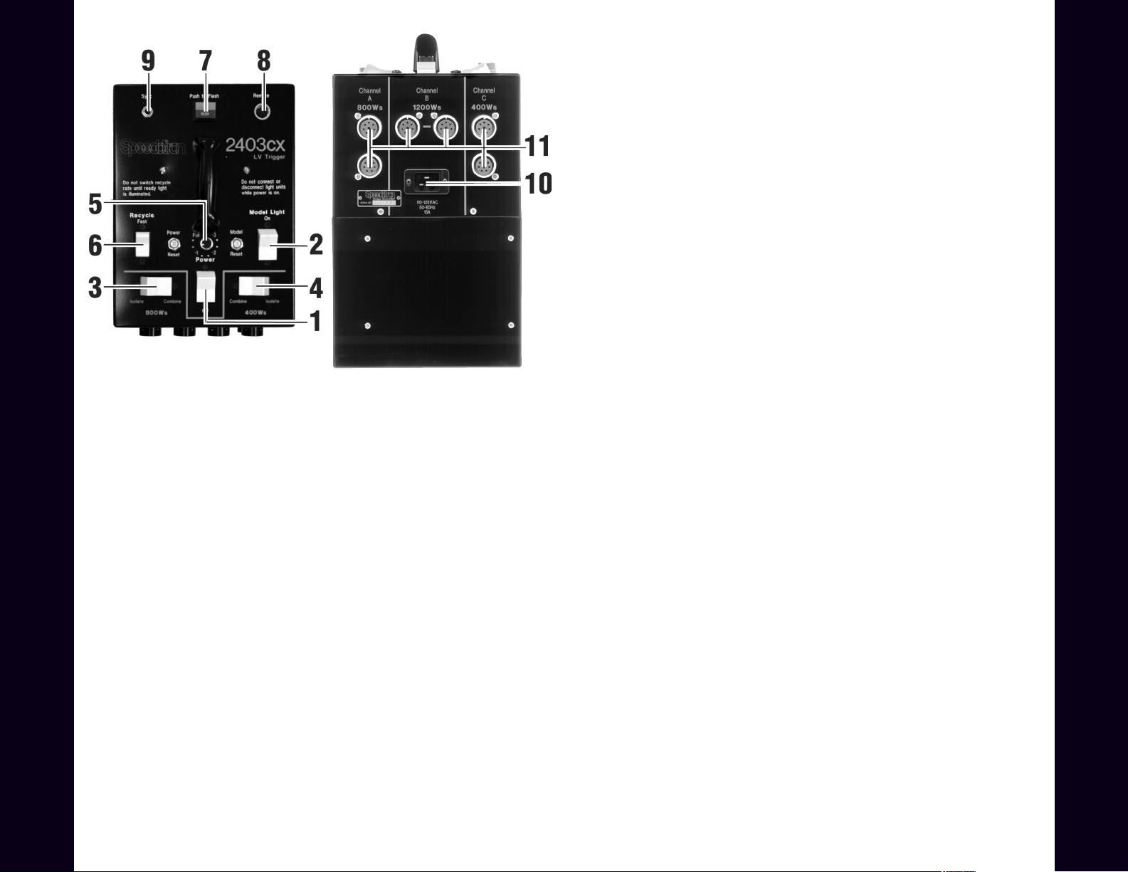
1) Power — turns power supply on and off.
2) Model Light — turns model lamps on and off.
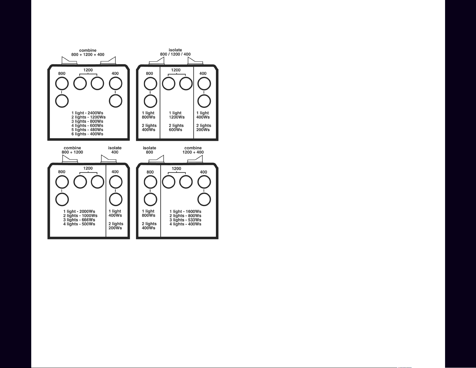
3) 800Ws Isolate/Combine — when in isolate, this switch isolates the
800Ws channel from the 1200Ws channel and provides two Light Unit
Outlets per channel. When in combine, will provide 2400Ws among 4 Light
Unit Outlets.
4) 400Ws Isolate/Combine — when in isolate, this switch isolates the
400Ws channel from the 1200Ws channel and provides two Light Unit
Outlets per channel. When in combine, will provide 1600Ws among four
Light Unit Outlets. (With both 800Ws and the 400Ws switches in combine,
2400Ws is available through any of the six Light Unit Outlets, divided equally.
See diagrams on the side of the power supply and page 15 for detailed
examples of the ratio system).
5) Variable Power Control — simultaneously controls power of all three
channels, with ten positions down to -3 stops (1/8 power). Power ratios
among the light units are unaffected since there is a proportional change in all
power levels.
6) Recycle Rate — controls recycle rate.
7)Charge/Ready/Push to Flash — red Charge light is illuminated whenever
the power supply is charging up or down to the selected level. Green Ready
light is lit whenever the 2403CX LV is fully charged to the selected power
2403CX LV • power supply
level. An audible beep will sound when the green Ready light comes on.
Push to Flash button is for manual triggering of flash for testing or open flash
application.
6
8) Remote — for use with optional Remote Variable Power Control (#11237)
to allow exposure bracketing from the camera position. The Variable Power
Control must be in the full position for the power levels to be correctly
indicated by the remote control.
9) Sync — socket to connect camera or slave to power supply.
10) Power Input — socket for AC power cord.
11) Light Unit Outlets (6) — sockets for connecting from one to six light
units to power supply.
2403CX LV Operating Instructions
In addition to the general instructions on page 4, the following
information and techniques are crucial for the proper use and care of the
2403CX LV power supply.
Set Isolate/Combine switches and Variable Power Control as desired.
See the side of the power supply for various ratio combinations. With the
Variable Power Control in the Full position, power is determined by the
choice of outlets and position of ratio switches. The Variable Power Control
simultaneously changes the power level of all three channels. Rotating the
Variable Power Control immediately adjusts the power level of the 2403CX
LV. The power supply does not need to be discharged between settings.
Turn Power Switch on. The red Charge indicator will illuminate. After a
few seconds, the green Ready indicator will illuminate and an audible beep
will sound. (The beep will not be produced when a very small power change is
made. Changing the power level by a third f-stop or so is done very rapidly
with the 2403CX LV; the Ready light will usually remain on) The power supply
is now charged to the selected level, and ready to fire. Do not immediately
fire the unit on the first use or when the unit has been idle for periods over 3
weeks. Allow several minutes for the power supply’s capacitors to form.
Push to Flash button may be depressed to verify proper system operation.
When Power is on, be sure Ready indicator is illuminated before switching
Power or Fast/Slow. Do not move these switches while the unit is recycling.
When disassembling the system, turn Power switch to the off position.
The 2403CX LV power supply will automatically discharge its storage
capacitors. Do not push the Push to Flash switch before turning power
supply off. This may damage power supply. Power supplies may flash their
light units when turned off. This is normal.
Unplug power cord from outlet, then disconnect light units from power
supply.
2403CX LV • power supply
7
Page 5
2403CX LV Power Ratios
2401sx LV • power supply
2401sx LV • power supply
8
9
Page 6

General Maintenance and Care
Trouble-shooting
maintenance and care
All Speedotron Black Line equipment is ruggedly built.
Nevertheless, it should be treated with the same care given to
other pieces of quality photographic equipment. To protect
the user, all Speedotron equipment is designed to be safe
when used in accordance with instructions. To assure the
maximum in safe, dependable service, the following
guidelines should be carefully observed.
• Avoid kinking or pulling cables. Disconnect cables by pulling on the
quick release only, except for the 206 light unit which has a threaded
ring. Never pull plugs out by the cable. Light cables as well as sync
cords and AC power cords should be occasionally checked for wear,
cracks, separation between cable and plug, and for indications of arcover.
• Do not wrap the light unit cables around the light units. Coiling cables
tightly stresses the internal wires and may lead to premature cable
failure. If possible, keep the coil diameter at least 10 inches.
• If a cable becomes frayed, the insulation damaged, or the connectors
bent or broken, have them repaired immediately.
• Keep all connectors, plugs and sockets free of dust, moisture and
corrosion.
• Do not connect or disconnect light units or insert or remove flash
tubes while the power supply is on.
• When using your equipment, be sure all cable, sync, power and flash
tube connections are completely and properly installed.
• Do not attempt to make repairs to your Speedotron equipment
yourself. It is very dangerous, and will void your warranty. Consult your
dealer regarding authorized service in your area, or return the
equipment to Speedotron. When you are not using your equipment, it
is recommended that you store it in a dry place. Equipment should be
charged up and flashed a few times at least once a month. This will
keep your equipment in top working condition for many years.
• With your light unit disconnected, occasionally remove the reflector
and clean the interior surface with a light solvent or soap and water.
Carefully remove the flash tube, and clean the glass cover. Only in this
way will you conserve a consistent color temperature and light output.
Dirt and dust deposits on the tube and reflector act like a filter to alter
color.
• To extend the life of the model lamp, it should be turned off after setup and focusing.
System will not work at all; no flash.
Check that sync cable, AC power cord and light unit cables are firmly and
properly attached. Check that the flash tube is firmly seated. Check that
Power switch is on.
Occasional failure of all light units to flash.
Check sync cable and light unit cable connections. Make sure that the
Ready indicator is illuminated before attempting to fire unit.
Occasional failure of one light unit only.
Check light unit cable connection. Inspect the cable. Check flash tube.
Make sure that the Ready indicator is illuminated before attempting to
fire unit.
Reduced light output.
Check to see if Ratio or Variable Power Control switch is in right position.
Check flash tube; check power supply by comparing to similar pack with
same light units if possible.
Flash tube glows after a flash (afterglow) and will not flash again
until glow is gone.
If confined to one light unit, check flash tube by substitution. If it
continues or all lights afterglow, power supply is at fault. If this is the
case, turn power supply off immediately! Power supply needs repair.
Ratio or Variable Power Control switch has no effect on recycle time
or light output.
Power supply needs repair.
Circuit breaker on power supply pops.
Check that all cables on power supply and light units are properly
connected. Also check for afterglow. If a circuit breaker blows, it is an
indication that something is wrong. Normal operation will not blow circuit
breakers.
Circuit breaker or fuse in studio blows.
Use slow setting on Recycle rate switch.
Model lamp fails to light on one light unit.
Check that the model lamp switch on that light unit is in the “ON”
position.
When checking power supplies, light units and cables, be sure that
Power is off. Look for blackened, discolored or burned pins and sockets.
If a Light Unit Outlet on the power supply is burned, blackened or
discolored, it must be replaced before it is used. It could damage light
units that are connected to it. Check that cables are not loose or frayed.
trouble shooting
1110
Page 7

FLASH DURATION (watt-seconds per light unit)
102 ----- ----- 1/225 1/400 1/670 1/1250
103** ----- ----- 1/450 1/770 1/1300 1/1800
MODEL Watt-secs: 9600 4800 2400 1200 600 300
202VF ----- ----- 1/300 1/500 1/900 1/1425
_____________________________________________________________________________________
If power is reduced by using the dial-down knob, durations will remain the same. All durations tested in accordance with ANSI PH3.40
206VF ----- 1/175 1/300 1/500* 1/900* 1/1425*
105 (2 cable) ----- 1/600 1/1175 1/2000 1/3570 1/5000
105 (4 cable) 1/400 1/600 1/1175 1/2000 ----- -----
_____________________________________________________________________________________
and using the 1005 power supply: 800Ws = 1/300sec., 400Ws = 1/500sec.
**Flash duration of 103 light unit using the 405 power supply: 400Ws = 1/500sec.;
*These power levels are reached by the use of the 14202 adapter cable & a standard outlet.
Section 2; “The time interval from the instant the flash reaches one-half of its peak intensity to the instant it decays to the same value”.
notes
*Guide # calculated at ISO 100, in ft. w/202VF Light, 11.5” reflector forward (35°) & back (90°) positions (except 4803, with 206VF light) **including handle
technical specifications
POWER SUPPLIES
12 13
(Watt-secs) 35°-90° (secs) CHANNELS COMB. DOWN VARIATIONS
(Watt-secs) (qty.-regular or color corrected)
405 400 290-160 1.3 2 6 9 54 Ratio, Dial-down power 5lbs / 6.5x4.375x7.2” **
1005 1000 408 1.6 3 12 10 120 Ratio, Dial-down power, Slave 7.9lbs / 8x4.375x9.5” **
MODEL MAX.POWER GUIDE NO. RECYCLE POWER RATIO DIAL TOTAL OUTPUT SPECIAL FEATURES WEIGHT/SIZE
______________________________________________________________________________________________________________________________________________________________________________________________________
Explorer 1500 1500 540 3.5 2 N/A continuous to -5 stops continuous BatteryPower,Ratio,Dial-downpower,Slave,UniversalVoltage input 24.9lbs / 9.5x5.4x11.7” **
2401sx 2400 710-380 2.0 3 53 NA 53 Ratio, LV Trigger, Forced air cooling 27lbs / 9x12x14”
4803cx LV 4800 1000-540 4.0 3 27 10 270 Ratio, Dial-down power & optional remote 43lbs / 9x14x14”
2405cx LV 2400 710-380 2.0 3 25 9 225 Ratio, Dial-down power & model lamp 23lbs / 6.4x8.8x13”
2403cx LV 2400 710-380 2.0 3 53 10 530 Ratio, Dial-down power & optional remote 28lbs / 9x12x14”
1205cx LV 1200 500-270 0.9 3 21 9 189 Ratio, Dial-down power & model lamp 15lbs / 6.4x8.8x10”
______________________________________________________________________________________________________________________________________________________________________________________________________
LIGHT UNITS
102 2400 1 - MW8QV or 1 - MW8QVC economical, general purpose
103 2400 1 - MW9Q or 1 - MW9QC lightweight, compact
MODEL MAX.POWER FLASH TUBES SPECIAL CHARACTERISTICS
202VF 2400 1 - MW20QV or 1 - MW20QVC variable focus, modular construction
_______________________________________________________________________________
Note: All Speedotron light units are fan-cooled and accept a 250W model lamp (except the low profile 103).
206VF 4800 1 - MW40QV or 1 - MW40QVC variable focus, high output
105 (2 cable) 4800 4 - MW24Q or 4 - MW24QC shortest flash duration
105 (4 cable) 9600 4 - MW24Q or 4 - MW24QC shortest flash duration, highest output
________________________________________________________________________________
Page 8

The Speedotron Plus•3 Protection Plan
The Speedotron Plus•3 Protection Plan is an extended service contract that lets you
add 3 years of factory service coverage to the 2-year limited warranty that comes with
Speedotron power supplies and lights plan goes into effect the day your original warranty
expires, so you end up with 5 full years of coverage. With the Plus-3 Protection Plan,
virtually all your service needs will be taken care of free of charge. All Plus-3 Protection
Plan customers get priority service, so you can have the security of knowing that your
equipment will be back on the lob as quickly as possible. The Speedotron Plus-3
Protection Plan can only be purchased at the time you buy your equipment. Flash tubes,
modeling lamps and shipping charges are not covered.
Terms & Conditions
1. This agreement covers both labor and materials necessary for repairing equipment which is in need
of service because of faulty materials or workmanship or breakdowns from normal use, except as
hereinafter provided. Damage to equipment or its parts arising out of misuse, abuse, negligence,
shipping or causes beyond Speedotron’s control are not covered. In addition, this agreement shall
become void if the equipment covered is used for rental or is modified, altered, or serviced by persons
other than those authorized by Speedotron, or if it is used with parts, accessories, or equipment not
intended for use with Speedotron equipment
2. This agreement is between Speedotron Corporation and the person named in the contract. Thus,
payment for Plus-3 Protection Plan Coverage should be made directly to Speedotron (not to a dealer)
within 30 days of the date the equipment is purchased
3. Service under this agreement will be performed only at the Speedotron factory in Chicago. Service
performed at any other service station, including those authorized by Speedotron, is not covered and
any service so performed is at the customers expense. Shipping charges, both to and from the Chicago
factory, are also the responsibility of the customer, and are not covered by this agreement. Shipping
charges to cover the return of your equipment by what-ever means you choose may be included with
requests for service, or equipment can be returned C.O.D. (freight collect).
4. This agreement is valid only for the equipment listed Any other piece of equipment or accessory is
not covered under this agreement, even if damaged while in use with the equipment covered Flash
tubes and modeling lamps are not covered. In addition, once this agreement is signed by Speedotron,
no other equipment may be added to it. Should you purchase additional equipment and wish to have it
covered, you must purchase additional Speedotron Plus-3 Protection Plan Service Contracts.
$. The equipment listed in this contract will be covered only while owned by the person named in the
contract. THIS AGREEMENT IS NOT TRANSFERABLE.
6. Equipment covered by the Speedotron Plus-3 Protection Plan Service Contract will be given priority
service This priority service will be given during the regular warranty period of the equipment as well as
when the Plus-3 Plan goes into effect.
7. Other than the obligations set forth herein, Speedotron disclaims all warranties, expressed or
implied, including any implied warranties of merchantability, fitness for use, or fitness for a particular
purpose. Speedotron shall not be responsible for any direct incidental or consequential damages,
including but not limited to damages arising out of the use or performance of the equipment covered,
or the loss of use of the equipment covered.
8. This agreement shall be governed by and construed according to the laws of the state of Illinois, in
which Speedotron is located. It constitutes the entire agreement between parties and may not be
modified except in writing signed by duly authorized officials of Speedotron Corporation and the
customer.
plus•3 protection plan
9. This agreement shall terminate on the expiration date indicated, and any repairs necessary after
that date are solely the responsibility of the customer
10. Due to U.S. Customs Service regulations, this agreement only applies to equipment shipped within
the United States (including U.S. territories).
14
The Speedotron Plus•3
Protection Plan Service Contract
To apply, fill out this form completely, sign it, and mail it along with a copy of the bill of sale
and warranty registration card for each piece of equipment to be covered to:
Speedotron Corporation
310 South Racine Avenue
Chicago, Illinois 60607
Once approved, this form will be returned to you and a copy will be kept in Speedotron’s
files. Please note that if these instructions are not properly followed, you application will be
returned to you.
The Speedotron Plus•3 Protection Plan Price List
For Speedotron Black Line Power Supplies, 4800Ws $125.00
For Speedotron Black Line Power Supplies, 2400Ws 95.00
For Speedotron Black Line Power Supplies,1200Ws or lower 75.00
For Speedotron Force 10 / Force 5 75.00
For Speedotron Brown Line Power Supplies, 800Ws or higher 50.00
For Speedotron Brown Line Power Supplies, 600Ws or lower 30.00
For any Speedotron Black Line or Brown Line Light Unit
(not including flash tubes or modeling lamps) 10.00
NOTE: All pieces of equipment must be covered individually.
Customer name __________________________________________________________________
Address _________________________________________________________________________
City___________________State ______________________Zip ____________________________
Phone, ________________Daytime ___________________Evenings _______________________
Equipment covered.
Model ____________Serial Number ______________ Plus-3 price $ __________________
Model ____________Serial Number ______________ Plus-3 price $ __________________
Model ____________Serial Number ______________Plus-3 price $ ___________________
Model ____________ Serial Number _____________ Plus-3 price $ __________________
Total amount due for coverage on equipment listed above $ _______________________
Note: A copy of the bill of sale and warranty registration card must be included for
each piece of equipment listed above. The copy of the bill of sale must show the
authorized dealer’s name, invoice number and date purchased. Speedotron Plus-3
Protection Plan coverage must be applied for within 30 days of the date the
equipment was purchased.
Page 9

I am enclosing a check for $ ________________________ the total amount due for
Speedotron Plus-3 Protection Plan Service Contract for the equipment l have listed.
Speedotron agrees to provide repair service for said equipment, should it become
necessary, according to the terms and conditions (see back) set forth in this agreement.
No terms or conditions, expressed or implied, are authorized unless they appear on the
original of this agreement. This agreement is not valid unless signed by both parties.
Customer acceptance:
I have read, fully understand, and agree to the terms and conditions of this agreement.
Customer Name _________________________________________________________________
Signature________________________________________________________________________
Speedotron acceptance:
Speedotron agrees to provide repair service for the equipment listed in this agreement,
according to the terms and conditions set forth herein.
Authorized Speedotron Official _____________________________________________________
Signature________________________________________________________________________
The Speedotron Plus-3 protection Plan
for the above listed equipment will expire on ________________________________________
When returning this Plus-3 Protection Plan
application, please include the following:
1. the completed application form,
2. completed warranty information card
3. a copy of sale invoice with the dealer’s name and address,
4. a check for the full amount of coverage for each piece of equipment to be covered
Send to:
Speedotron Corporation
310 South Racine Avenue
Chicago, Illinois 60607
 Loading...