

SpeedLeader DVX402 User Manual
SHENZHEN SPEEDLEADER TECHNOLOGY
User Manual
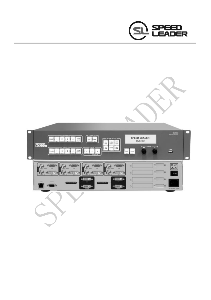
DVX402
Seamless Switch
About the Manual
Without the written permission of the company, it is forbidden for any company or
individual to imitate, copy, or transcribe part or all of the contents of the manual. It is not
allowed to have the commodity publicity or achieve any commercial or profit-seeking
purpose in any form (electronic form, mechanical form, photocopying form, recording
form, or other possible ways).
Please carefully read this manual before using this equipment. All the product
specifications and information mentioned in the manual are only for reference. If there is
the content updating, the company will not make further notice. Unless there is a special
agreement, this manual is only taken as an instruction, and all statements and information
will not constitute a guarantee of any kind.
Brand Royalty
VGA and XGA are the registered trademarks of IBM Corporation.
VESA is a trademark of the Video Electronics Standards Association.
The logo of HDMI and High-Definition Multimedia Interface are the trademark of HDMI
Licensing LLC.
Safety Instructions
This symbol prompts the user that there are the important operation and
maintenance instructions in the user manual.
Page 1 of 55

This symbol warns the user that there is the hazardous voltage exposed inside
the equipment and there is an electric shock hazard.
This equipment must be connected with ground wire.
This equipment needs a rated power voltage. Ensure that the input voltage error
should be between - 10% and +10%.
Do not connect AC power cord with another AC power cord which may lead to
excessive noise.
Please use the equipment when the surrounding temperature is from -10 ℃ to 45 ℃,
and the relative humidity is 90% or less than that.
Do not use this equipment in certain special circumstances, such as, closing to a heat
source, which may cause overheating of the equipment and damage it. Please use it
in a well-ventilated place and pay attention not to block the equipment vents.
Do not expose this equipment in the place which has the possibility for accidental
collision or vibration, and reinforcement processing is necessary in the vibration
place.
When you use the equipment, please make sure that there are no objects, such as
water and metal objects, inside the equipment. Otherwise, it will damage the
equipment and cause a fire.
If there is any irregularity or abnormality for the equipment, please immediately turn
off the power supply, disconnect the AC power cord, and see “Trouble Clearing”.
If this equipment is damaged, do not disassemble it. Please contact our maintenance
service department.
Page 2 of 55

Contents
Overview ....................................................................................................................... 5
Application .................................................................................................................... 6
Installation .................................................................................................................... 7
Install DVX402 ..................................................................................................... 7
Rear Panel............................................................................................................. 8
Operation Interface ...................................................................................................... 11
Menu System ................................................................................................................ 15
Menu System Overview ...................................................................................... 15
Main Menu System ............................................................................................. 17
Automatic Menu ................................................................................................. 18
Input Menu ......................................................................................................... 19
Output Menu ....................................................................................................... 21
Special Effects Menu…………………..………………………………...………...22
Layer Menu ........................................................................................................ 24
Logo Menu ......................................................................................................... 29
Preview Menu ................................................................ ................................ ..... 30
System Menu ...................................................................................................... 31
Operation .................................................................................................................... 33
Factory Reset Operation ................................ ...................................................... 33
Output Resolution setting .................................................................................... 34
Signal Input ........................................................................................................ 34
Switch ................................................................................................................ 36
Set Fade Time and Preview Switching Mode........................................................ 36
Layer Operation .................................................................................................. 37
AddingLayer………………………………………………………………………37
DeleteLayer……………………………………………………………… ………38
Layer Priority…………………………………………………………………….. 38
Window Size and Position …………………………………………………………38
Crop Size and Position of Picture ……………………………………….….…38
Page 3 of 55

Contrast………………………………………………………………………………......44
Save and Recall of the Preset ................................................................ ............... 45
Transfer of the Preset………………………………………………………..….…46
Logo capture and Transfer………………………………………………………..47
Logo or Black Field Transfer…………………………………………………..….50
Specifications…………………………………………………………………………....52
Page 4 of 55

Overview
DVX402 integrates 4 channel independent image processing engine, which can
perfectly achieve seamless switching and high-definition image analysis conversion. It has
the function of preview edition, program output, switching transition, LOGO capture and
insertion and screen freezing, which can also realize variety of advanced functions
required in a high-end presentation environment.
DVX402 has a 4-channel fully configurable input, which can access 16 channels of
video input, including 4-channel DVI, 4-channel VGA, 4-channel VID and 4-channel
3G-SDI (optional), and each channel can receive SD or HD video signals.
DVX402 has 2-channel output, the main channel of which is the live program output,
and the vice channel of which is preview output. Program and preview output interface has
two DVI and one VGA, with the highest resolution up to 1920 x 1200 @ 60Hz or 2048 x
1152 @ 60Hz.
More Operating Layers: DVX402 has four layers, and a single output channel can
output three layers at most. Each layer has an independent parameter setting, and the user
can edit the position, size, color, LOGO of each layer. It has real-time save function that
means it can restore the state before shutdown automatically after power failure.
Perfect Seamless Transitions Effects: DVX402 is built-in high-performance image
resolution converter, which can receive more-channel video signal, including 4-channel
3G-SDI signal (optional), and can have fade switch among any signal source. The
switching time can be adjusted from 0 to 5 seconds.
DVX402 has rich controllable functions, which is very suitable for the company
conference room, auditorium, church or other on-site activities. All the settings and
operations can be done by the front keys and RS-232/IP Link.
Page 5 of 55
Application
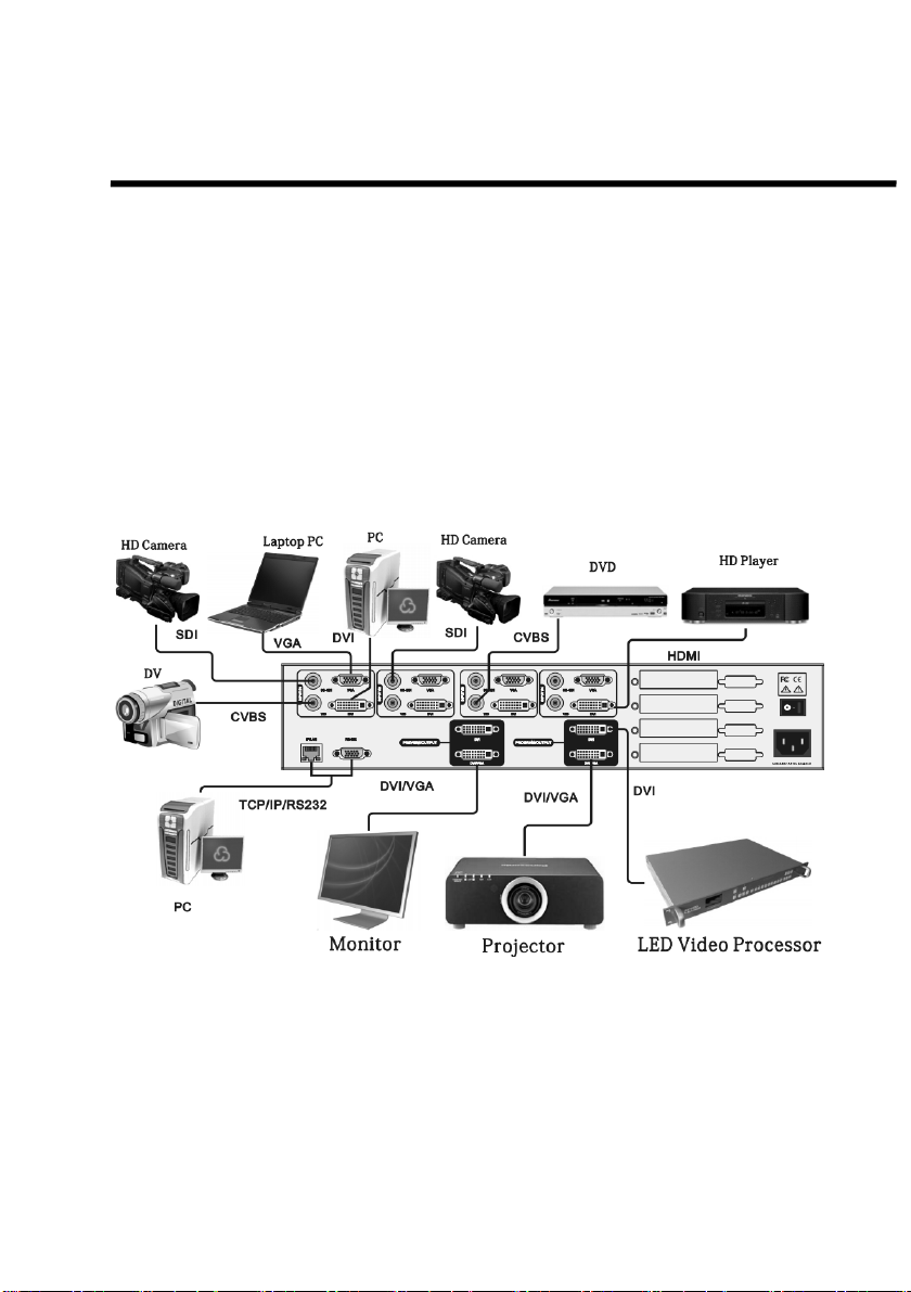
Figure 1-1 shows a typical application of DVX402. DVX402 receives a variety of
signal and resolution input, supporting the video input from the low resolution to high
resolution as follows:
VGA (XGA, WUXGA)
DVI (Compatible HDMI 1.3)
Composite Video (NTSC, PAL, SECAM)
SD/HD/3G-SDI video (optional)
Figure 1-1 Application of DVX402
Page 6 of 55

DVX402 has rich input and output interfaces, which can switch in VGA and DVI
signal of desktop computer, laptop, SDI (optional) signal of high-definition camera, and
DV and DVD video signal. Both the outputs of preview and program have two DVI
interface and a VGA interface, which can meet the various needs of users.
DVX402 has two-channel outputs, one channel can be connected to preview display;
and the other channel can be connected to the projector or LED video wall. After editing
images after the preview display, the user can follow the switch or exchange the switch
to the video wall. If the user needs to connect the LED video wall, it can be connected to
LED video processor, and then output it to the LED video wall. Program output of
DVX402 can also be connected to the LED video processor or LED video splicing
processor, and the switch does not need to zoom the image and the DVI output of the
program is directly connected to the video processor. If necessary, the user can use the
software or the console to have full control on DVX402.
Installation
Install DVX402
The user can choose whether to install DVX402 to rack or flight case. DVX402 is a
standard 2U chassis, with the size of 8.8cm (Height) x 44cm (Width) x 33.5CM (Depth).
While installing, please avoid scratching the case and use cushion for fixing suspension
loop.
Page 7 of 55
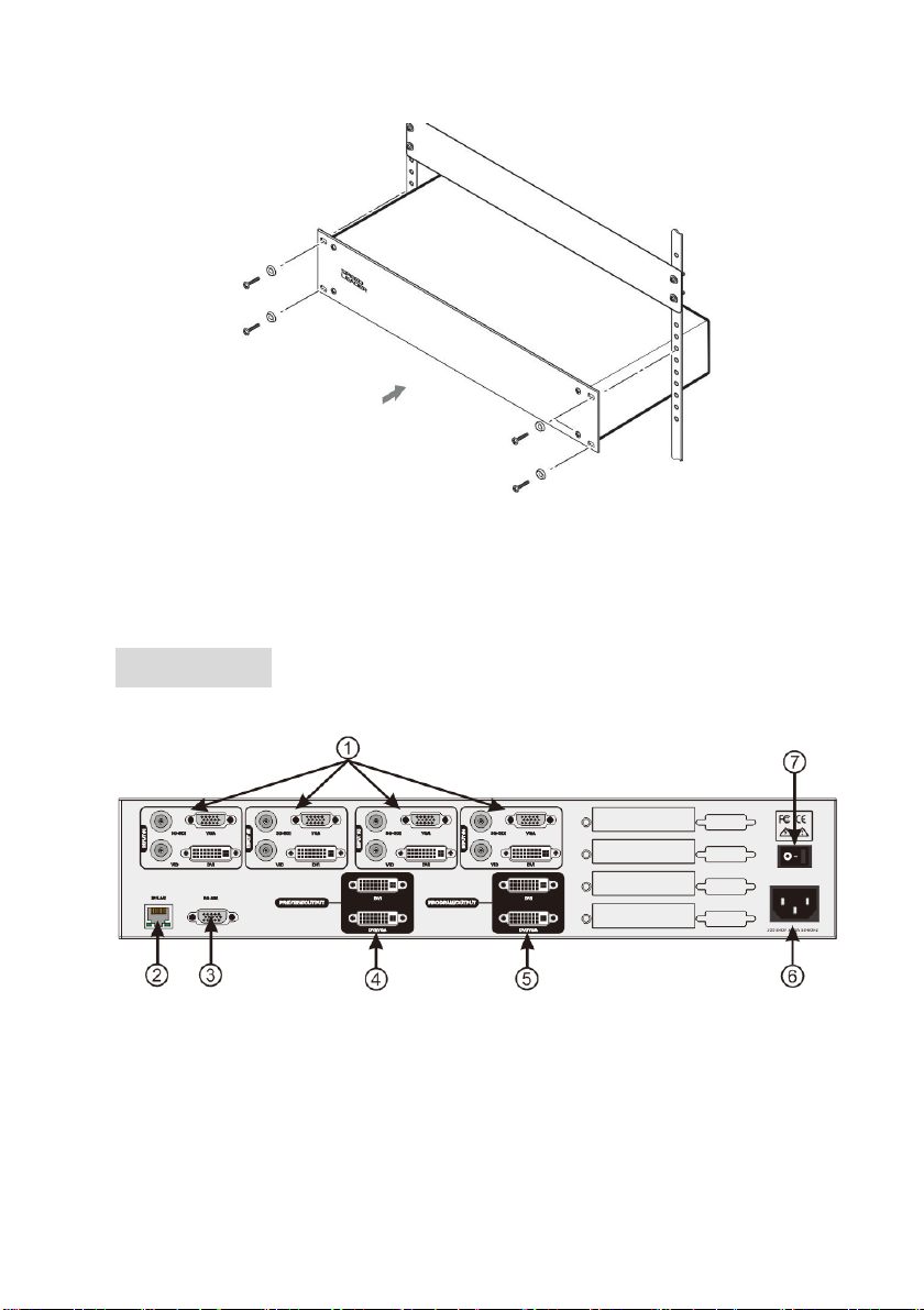
Rear Panel
Figure 2-2 Connection Terminals of DVX402 Rear Panel
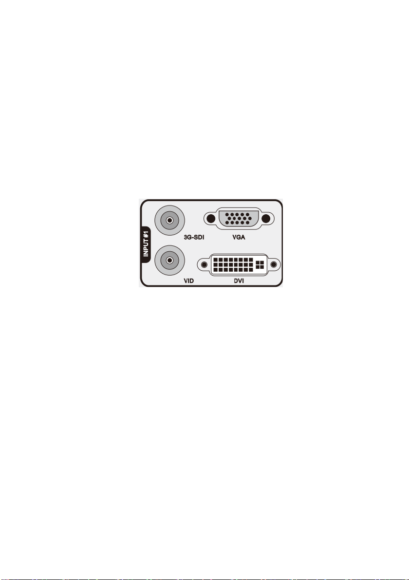
① # 1 ~ # 4 Channel Video Input
Figure 2-1 Install DVX402
It can receive a 4-channel video at the same time, and each channel can receive VGA,
DVI, HDMI (DVI terminal), VID (CVBS) and SDI (optional). DVX402 offers a number
Page 8 of 55
of input interfaces which can connect 16-channel video. After a one-time access, the user
can quickly switch video source without reconnection.
The following are the corresponding terminals for the input interfaces:
DVI input - DVI-D VGA input - DB15
SDI input (optional) - BNC VID input - BNC
Figure 2-3 DVX402 Channel # 1 Input Interface
②③ Communication Interface
② TCP / IP interface, using RJ-45 terminal, is reserved for the communication interface.
③ RS-232 interface, using DB9 terminal if it is connected by computer’s RS-232 or
console, resolution adjustment, channel selection and seamless switch to DVX402 can be
operated by it.
④ Preview Video Output Interface
Preview output is normally connected to the preview display. There are two video
output interface in the preview channel, and has two DVI-I seats, of which DVI / VGA
interface can output DVI and VGA signal. When using VGA output, DVI-VGA adapter
Page 9 of 55
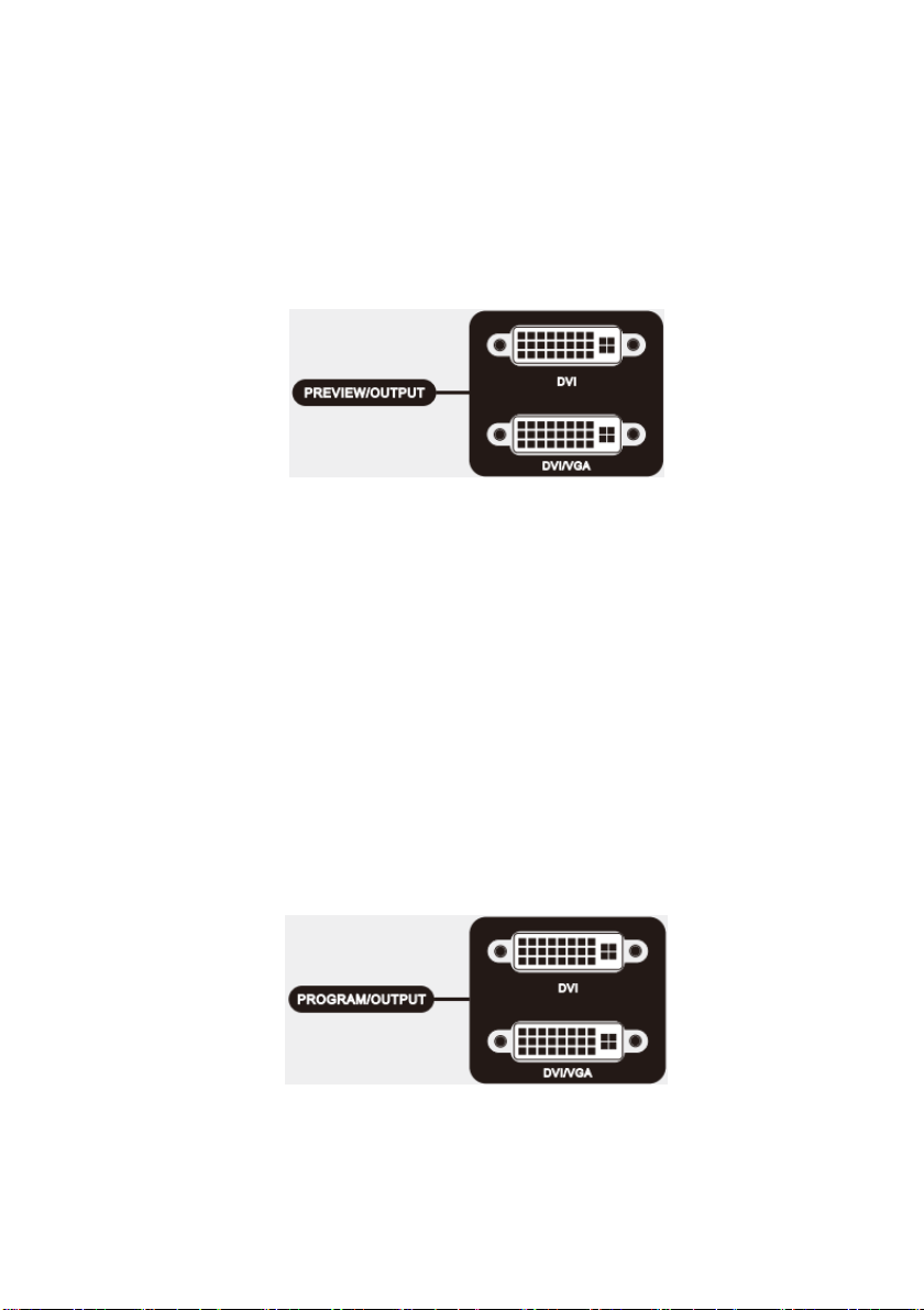
need to be connected to the DVI / VGA interface. The video image and resolution
outputted by the two interfaces are the same, which can be switched in multiple monitors;
therefore, both the operator and the commander can see the switching picture.
Figure 2-4 DVX402 Preview Output Interface
⑤ Program Video Output Interface
The program output channel has two video output interface, using two DVI-I
terminals, of which DVI / VGA interface can output DVI and VGA signal. When using
VGA output, DVI-VGA adapter need to be connected to the DVI / VGA interface. The
video image and resolution outputted by the two interfaces are the same. Normally, DVI is
outputted to the LED sending card or projector. The interface output resolution can change
by itself, with the resolution output up to 2048 x 1152.
Figure 2-5 DVX402 Program Output Interface
⑥ ⑦ AC Power Connector and AC Switch
Page 10 of 55
DVX402 provides a standard IEC power terminal with the input power of 100 ~
240VAC, 50Hz or 60Hz, at the same time, the ground wire of the power supply must be
grounded to avoid equipment damage or the electric shock to human body.
Operation Interface
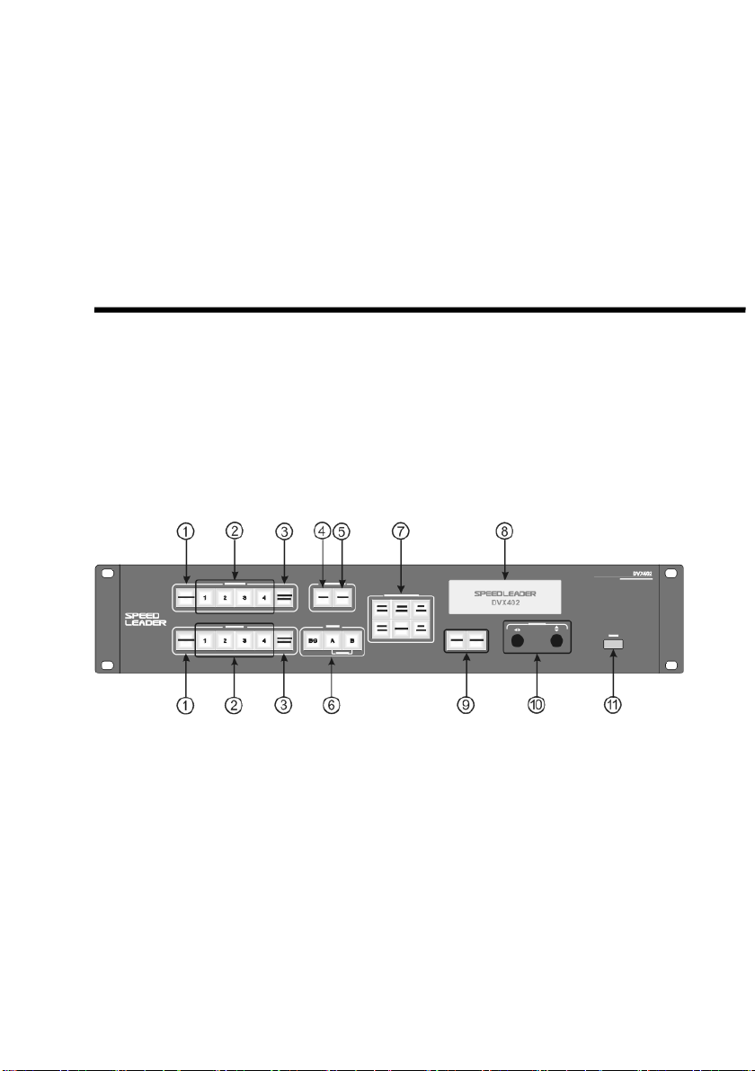
All the control and instruction of the switcher are set on the front panel (see Figure
3-1). These keys provide yellow and green background lights, which indicate the current
input selection and layer selection. The user can re-paste the character or graphic label on
the program and preview input selective keys (1, 2, 3, and 4). A 240×64 LCD window
indicates the current state of the seamless switcher, menu selection, data status, and other
system parameters.
Figure 3-1 DVX402 Front Panel
① FREEZE: Screen Freeze Key
There is FREEZE key in PROGRAM and PREVIEW key area, which can lock the
currently selected input picture and show it to the program output or preview output. When
FREEZE key is working, the key shows green light, and all the input keys (1~4 key) will
be shielded. But if the user presses the key again or selects other input, the frozen frame
will be canceled.
Page 11 of 55

②Input Selection Key
These two groups of INPUT # 1~ # 4 are to choose input source and then output to
the program or preview display. When the input channel is selected, the key will show
yellow light. DVX402 will record every input video data, such as, layer position, size,
brightness, crop mode.
③ LOGO / BLACK Key
There is LOGO / BLACK key separately in PROGRAM and PREVIEW key area,
which can output the stored logo or black to the preview output or program. It is first
edited in preview display and then it would be switched into program output. When press
LOGO / BLACK key, the key will flash yellow light, and all input key (1to 4 key) in the
current layer will be masked, until the user presses the key again to cancel LOGO /
BLACK function.
④ CUT Key
Pressing the CUT key can make the current preview image directly switch into the
program output, without any additional transition effects.
⑤ FADE Key
Pressing the FADE key can make the current preview image directly switch into the
program output, realizing fade switch. The preview shows the smooth switch to the
program output, achieving perfect seamless switch.
⑥ Layer Selection
Page 12 of 55
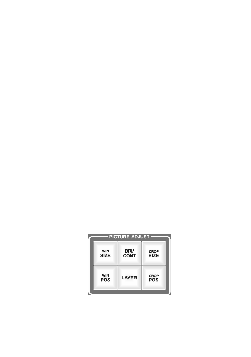
Figure 3-2 DVX402 Front Panel: Layer Key Area
There are three keys in LAYER key area, respectively BG key, A key and B key,
with the corresponding switch BG layer, A layer and B layer. After selecting layer, signal
switch, position adjustment, screen size adjustment and crop adjustment can be operated.
BG layer is called background layer, located in the bottom, under the A layer and B
layer, which cannot change the layer stacking order. A layer and B layer is called
superimposed layer, indicating by MIXER, which can modify the layer stacking order, and
can also set superimposed layer separation. About the operation of the layer, it will be
described in detail in the following sections.
⑦ PICTURE ADJUST Key
Pressing the key within the PICTURE ADJUST key area can change the parameters
of the current layer. After choosing the layer and pressing the image property key in the
PICTURE ADJUST key area, the user can adjust the parameters of the currently selected
layer.
Figure 3-3 PICTURE ADJUST Key Area
Page 13 of 55

WIN SIZE: the layer size, after selecting the layer, the user should press the WIN
SIZE key to enter the settings, and using knob, the user can adjust the pantograph ratio of
the layer.
WIN POS: layer position, after selecting the layer, the user should press the WIN
POS key to enter the settings, and using knob, the user can adjust the position of the layer.
BRI/CONT: brightness and contrast, after selecting the layer, the user should press
the BRI/CONT key to enter the settings, and using knob, the user can adjust the brightness
and contrast of the layer.
Layer: after selecting the layer, the user should press the LAYER key to enter the
settings, and can delete the layer or change the layer stacking order.
CROP SIZE: image crop size, after selecting the layer, the user should press the
CROP SIZE key to enter the settings, and using the knob, the user can adjust the horizontal
and vertical total pixels of the layer.
CROP POS: image crop position, after selecting the layer, the user should press the
CROP POS key to enter the settings, and using the knob, the user can adjust the position of
crop window of the image.
⑧ State Display
DVX402 has a 240 x 64 LCD window indicating the current state of the switch, menu
selection, data state and other system parameters, which will be described in detail next.
⑨ Menu Operation
MENU-menu key: press the Menu key to enter the main menu system or return to the
previous menu, whose function will be introduced in detail in the following parts.
ENTER-confirming key: which means to enter a menu or confirm the operation.
Page 14 of 55

⑩ : horizontal adjustment knob; and : vertical adjustment knob: which can adjust
menu options and parameters, or adjust the size and position of the layer.
⑪ USB interface
The USB communications interface or provide 5VDC power supply to the USB
device.
Menu System
Menu System Overview
DVX402 has a convenient menu system; Figure 4-1 shows the default display menu
of DVX402 after electrifying. The user can observe the corresponding source and other
important information of the current preview and program layers.
Page 15 of 55
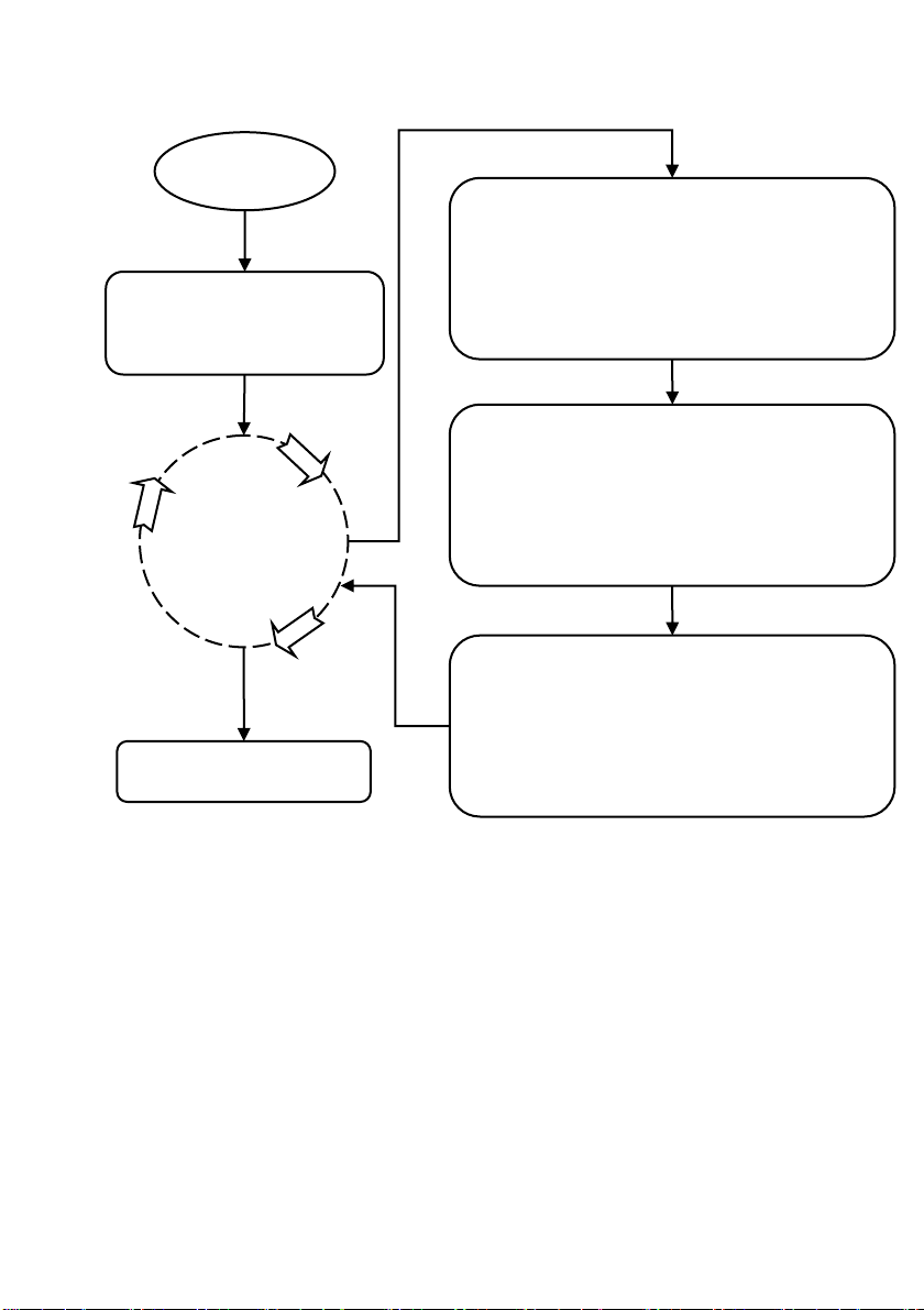
MENU
Electrify
Speed Leader
DVX402
Preview
BG:#1 <DVI 1920x1080/60>
A :#2 <VGA 1024x768/60>
B:#3 <DVI 1280x720/60>
Program
BG:#4 <DVI 1920x1080/60>
A:#3 <DVI 1280x720/60>
B:off
Resolution 1920x1080/60
Mix layer split on
Preview switch swap
Fade time 1.5 s
System Main Menu
Default
Figure 4-1 System Menu Flowchart
There are four keys to operate the menu and change the parameters, namely:
MENU key: press this key to activate the main menu, and after entering the main menu,
press the MENU key to return to upper step of the menu.
ENTER key: it is confirmation key. By pressing the ENTER key, the user can enter to
the sub-menu or change the operation.
Page 16 of 55
 Loading...