

Page 1
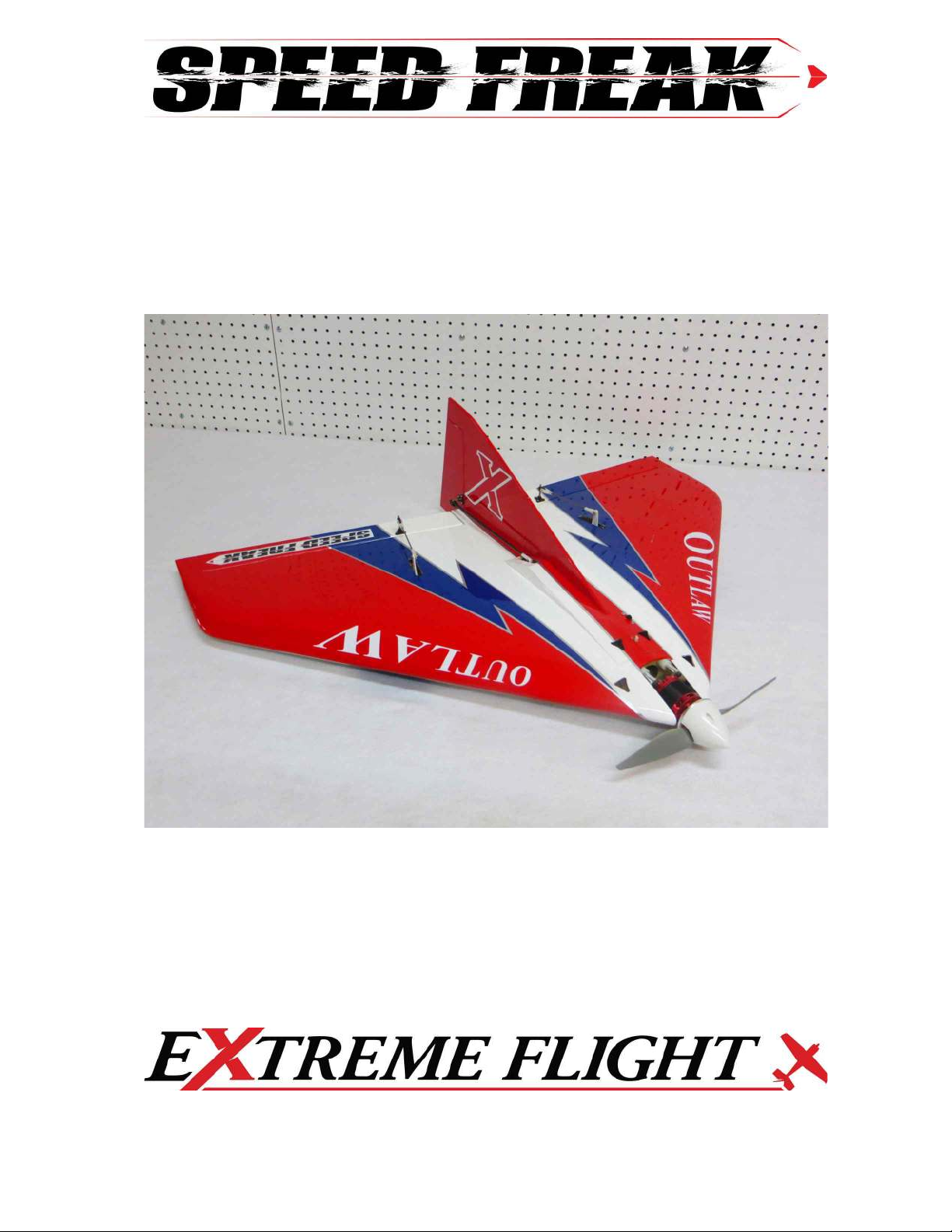
E-OUTLAW
High Speed Delta Wing ARF
©Copyright 2016 EXTREME FLIGHT RC, Ltd.
Page 2
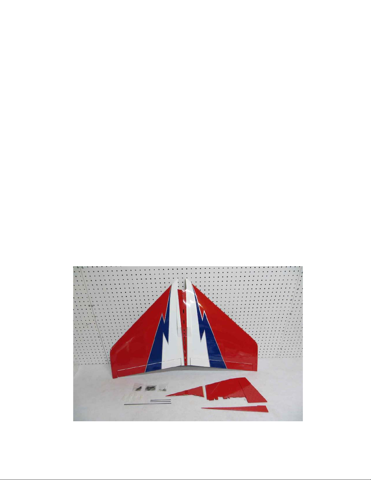
Thanks for your purchase of the Speed Freak Outlaw Delta wing ARF. Designed by 9
time NCFFA champion Jerry L. Smith of Paducah Kentucky, the Outlaw is a very
unique high performance aircraft that possesses a very wide flight envelope and is
capable of some very interesting maneuvers unique to this design. Jerry has been flying
this aircraft on the air show circuit for several years now and it always gets the crowd
fired up and asking “where can I get one?” Previously the Outlaw was available in a
short kit and it required a bit of time and modeling skill to assemble properly. The
Outlaw features a progressive airfoil that transitions between the root and tip rib and also
has anhedral built in. Noted aerodynamicist Robert Vess assisted Jerry with the design
and this unique airfoil and planform are part of what makes the Outlaw perform as it
does. It also made the Outlaw difficult to build correctly for most modelers. Extreme
Flight engineers spent many hours perfecting the construction and assembly of this
aircraft and tested many prototypes to make sure the Outlaw ARF lived up to Jerry’s
expectations, while making it easy for the average modeler to assemble. For most
modelers the Outlaw ARF can be assembled and ready for flight in a couple of evenings.
We are very excited to release the Outlaw in a dedicated electric version as the first
model in the new Speed Freak lineup. The design has been modified to allow for easy
installation of electric power systems and a spring loaded hatch allows instant access to
your battery and the aircraft interior. The Outlaw requires 2 standard size metal geared
servos with 100+ oz./in. of torque for the elevons and a metal geared mini servo for the
rudder. The recommended Xpwr power system provides incredible performance on 6S
Lipo power (2700-3800 mah suggested).
The Outlaw is a very unique aircraft and we are honored to have worked with Jerry to
bring it to market. The only thing more fun than flying an Outlaw is flying several of
them together with your buddies! Thanks again for your purchase, now let’s get on with
the assembly and get this thing in the air!
2
Page 3

Tips for Success-Please read before beginning assembly!!!
1. Read the instruction manual thoroughly before starting assembly.
2. We are very pleased with the level of craftsmanship exhibited by the workers in
our factory. However, these are mass produced models. As with any ARF, take a
few minutes to go over the model and add CA to high stress areas such as the
firewall, servo mounts or any joints that appear to need more glue.
3. Take a few minutes and go over the covering with a hot iron. Make sure all edges
are sealed and pay special attention to thin stripes.
4. Decals- clean your airplane with glass cleaner and a paper towel before starting to
apply the decals. Mist the area where the decal will be applied with glass cleaner
or water mixed with a little bit of soap. Use scissors to remove the decal from the
sheet. For best results cut as close to the edges of the decal as possible. Position
the decal in place and use a credit card or rubber squeegee to push the excess
liquid from under the decal and allow to dry. You may need to secure the edges
of the decal with masking tape to prevent them from rolling up until the solution
has dried and evaporated.
Items required for assembly and completion:
30 minute epoxy
Thin and medium CA
Assortment of screwdrivers and ball drivers
Electric drill with assortment of bits
Electric power system (Xpwr T3520 and Airboss ESC highly recommended)
2 High torque metal geared servos (100+ oz. in) for elevon actuation
1 Metal geared mini servo for rudder actuation (Hitec 5245, 7245, etc.)
Dubro Super Strength XL servo arms
12 inch servo extension for ESC lead to receiver.
Prop for your motor (For the T3520 we recommend APC 9x7)
52mm EF spinner
Adhesive backed Velcro
Velcro battery strap.
3
Page 4
Assembly
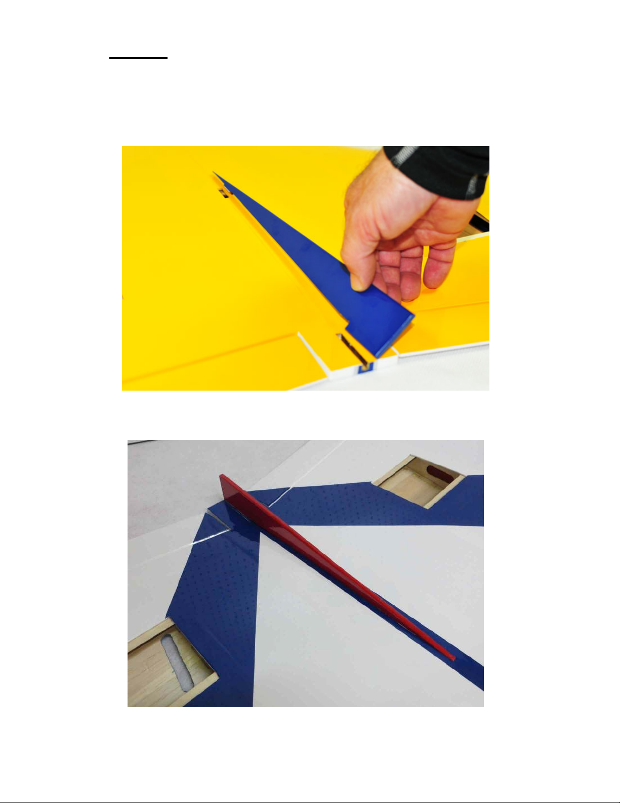
1. First let’s install the lower vertical fin. It’s much easier if this is installed before
gluing on the upper vertical fin and rudder. Test fit the fin in position. Glue
the lower fin in place with 30 minute epoxy, making sure it is aligned properly.
4
Page 5
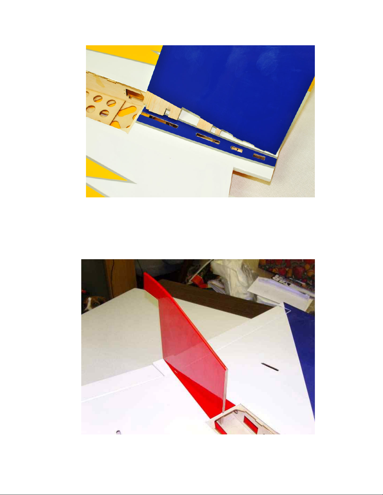
2. Once the lower stab is dry, flip the wing over and we’ll install the top vertical fin.
3. The vertical fin has a series of tabs and notches to add rigidity and allow for easy
alignment of the vertical fin. Trial fit the fin in place to insure proper alignment.
Once satisfied glue the fin in place with 30 minute epoxy. Check from several
angles to make sure the vertical fin is properly aligned and square to the wing.
5
Page 6
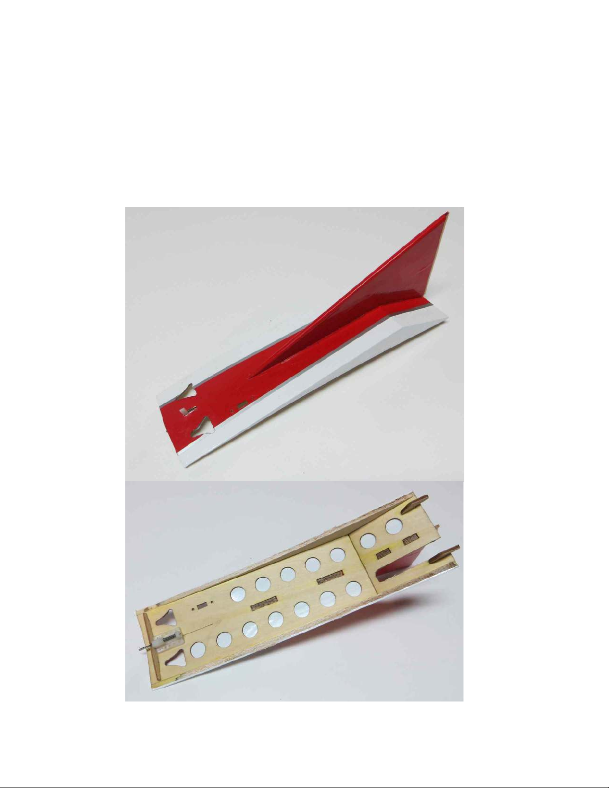
4. Next let’s assemble the forward portion of the vertical fin and top hatch. Use a
sharp hobby knife and metal straight edge to remove the covering from the top of
the hatch where the forward portion of the vertical fin will mount.
5. Glue the forward portion of the vertical fin to the hatch with 30 minute epoxy,
making sure the fin is perpendicular to the top of the hatch. Trial fit before gluing
and it is also a good idea to test fit the fin/hatch to the aircraft to be sure the
tongue and groove portion is properly aligned with the fixed portion of the
vertical fin. It is also a good time to remove the covering over the NACA
air ducts in the forward section of the hatch. This will allow additional
cooling air to enter the battery compartment.
6
Page 7
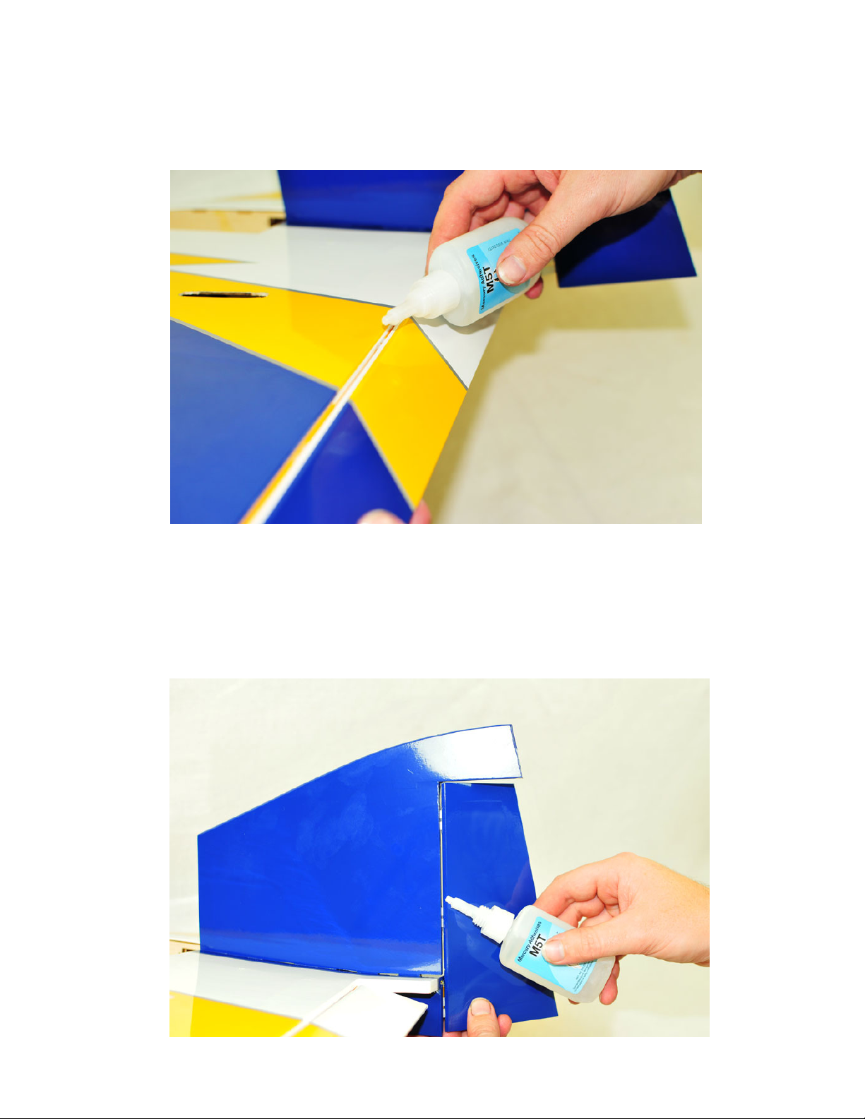
6. Slide the elevons into position and onto the hinges and secure with thin CA.
Make sure to center the hinges in their slot before gluing, and leave enough of a
gap to ensure maximum deflection. Once dry seal the hinge gap with a strip of
covering or Blenderm tape.
7. Slide the rudder into position on the hinges and secure with thin CA, again
leaving enough gap to allow for maximum deflection. Make sure to install the
bottom hinge that glues into the lower vertical fin. Seal this hinge line as you did
for the elevons.
7
Page 8
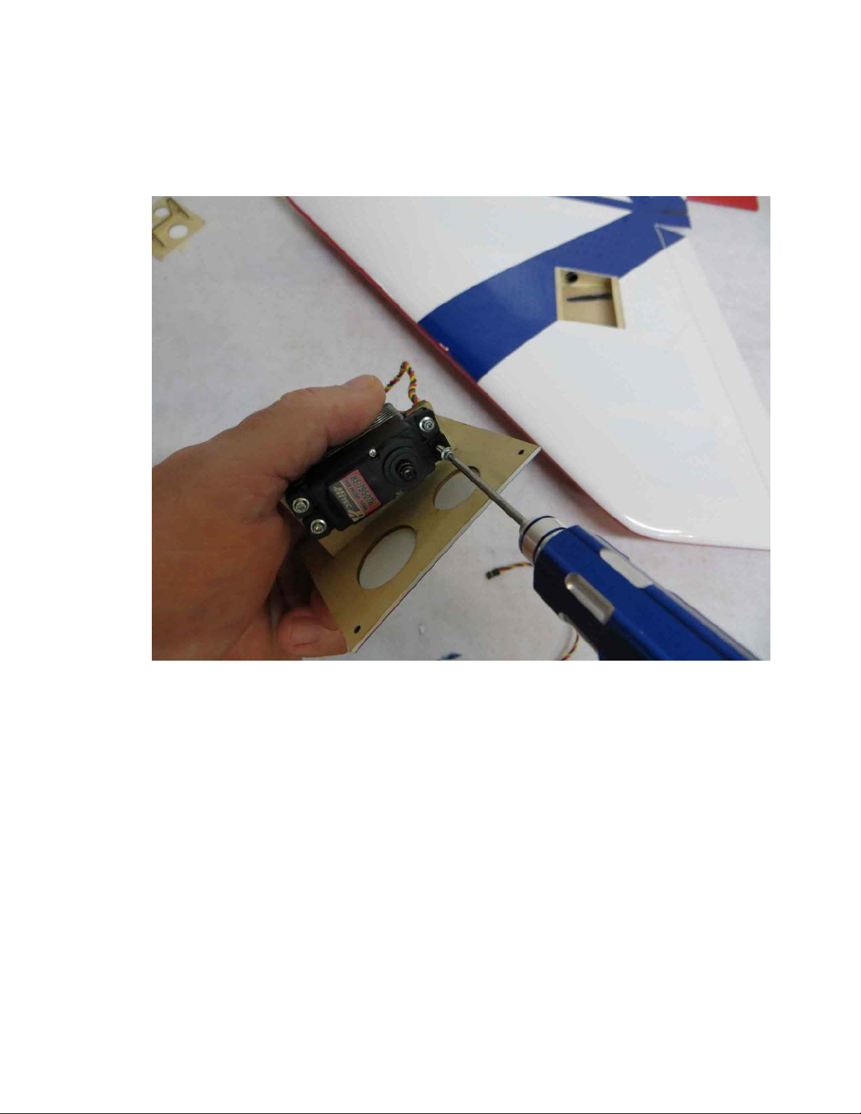
8. Electronically center your servos and place the servo arms on the output shaft and
secure with the supplied screws. We highly recommend the use of the Dubro XL
Super Strength servo arms for best alignment with the opening in the top of the wing.
Use the manufacturer supplied hardware to mount your servos to the servo hatches.
Pay close attention here to the pictures to make sure you mount the servo properly or
it will not fit into the wing. The output shaft is oriented toward the rear of the plane.
8
Page 9
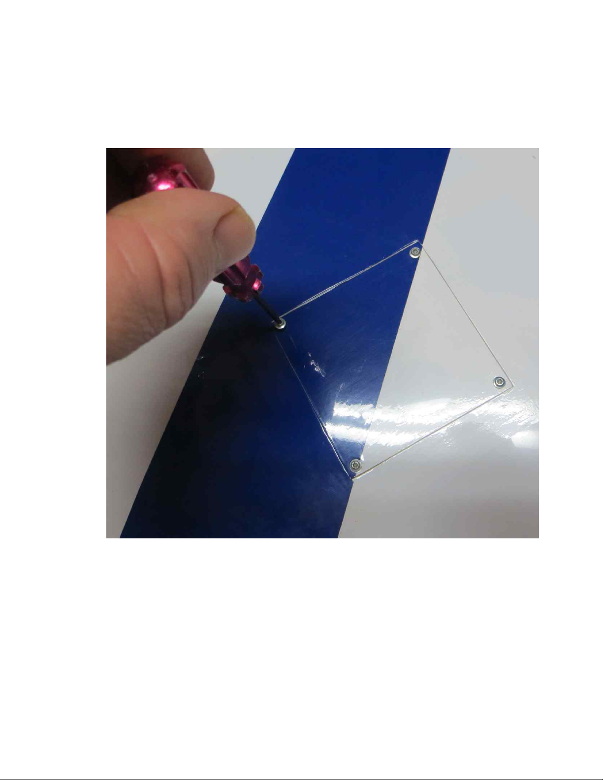
9. Place the servo hatch into position, being sure to route the servo wire into the radio
compartment through the fiberglass tube that is pre-installed in the wing. Secure
the hatch with the provided screws, one at each corner. I highly recommend
installing the screws then removing them and the hatch and putting a single drop
of thin CA into each hole to harden the threads. You may find that you need to
enlarge the width of the servo arm slot in the top of the wing slightly to
accommodate different makes of servo. This is easily done with a rotary tool and
¼” sanding drum attachment. Again the Dubro Super Strength servo arms work
best here.
9
Page 10
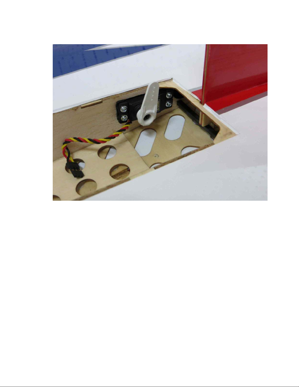
10. Use the manufacturer supplied hardware to mount the rudder servo in the interior
wing rib as shown with the output shaft toward the front of the plane.
10
Page 11
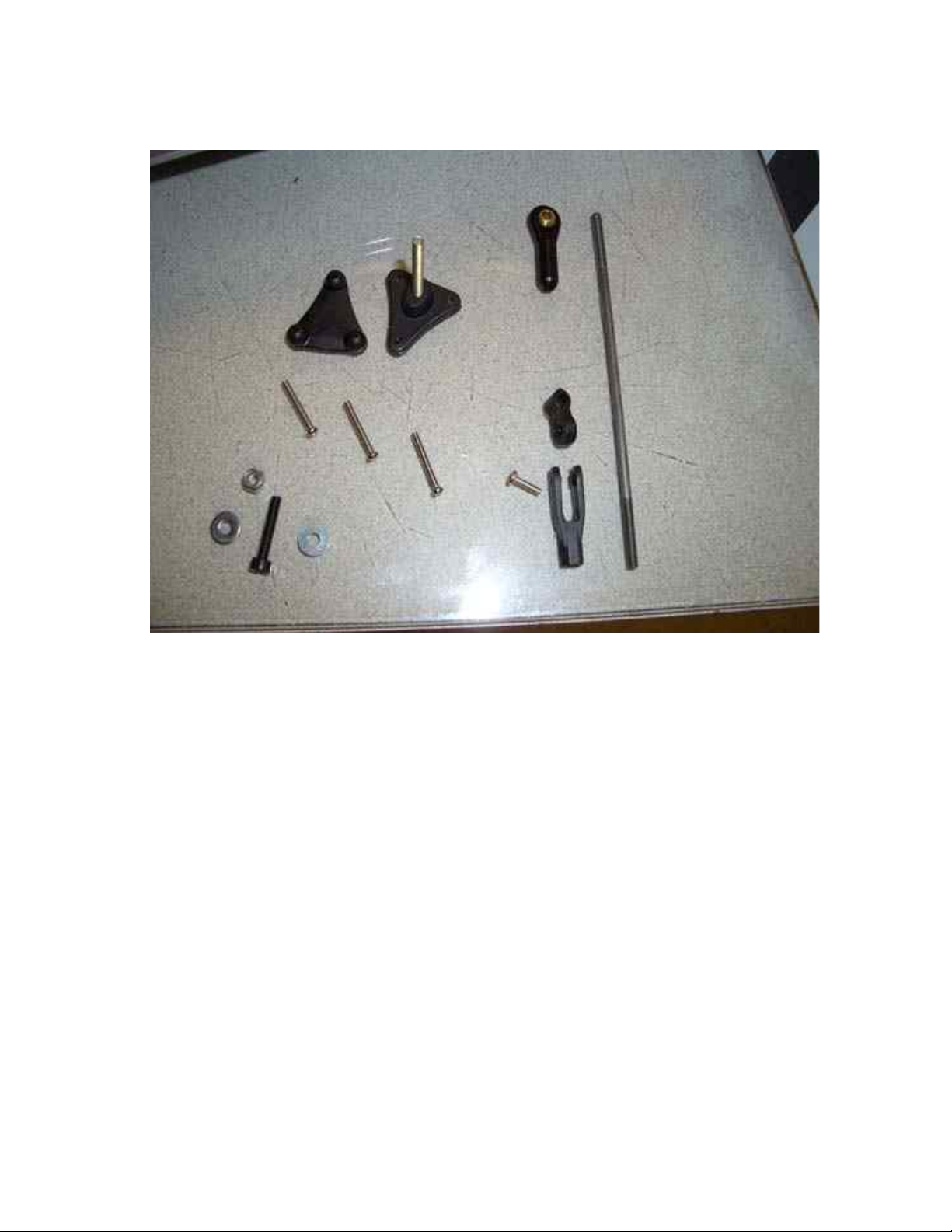
11. Now let's install the control surface linkages. Locate the 3 sets of triangle
shaped control horns and bases, pushrods, ball links, clevises and screws.
11
Page 12
12. Use a straight edge aligned with the protruding servo arm to determine location
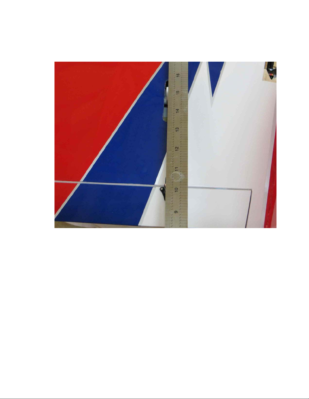
for the elevon control horns to be mounted. Place the triangle shaped horn in
place and drill through the control surface at the location of the 3 holes. Use the
provided screws to secure the control horn to the surface and thread them into the
base plate on the bottom of the surface. Make sure to position the horn so that the
pivot point of the linkage is directly over the hinge line.
12
Page 13
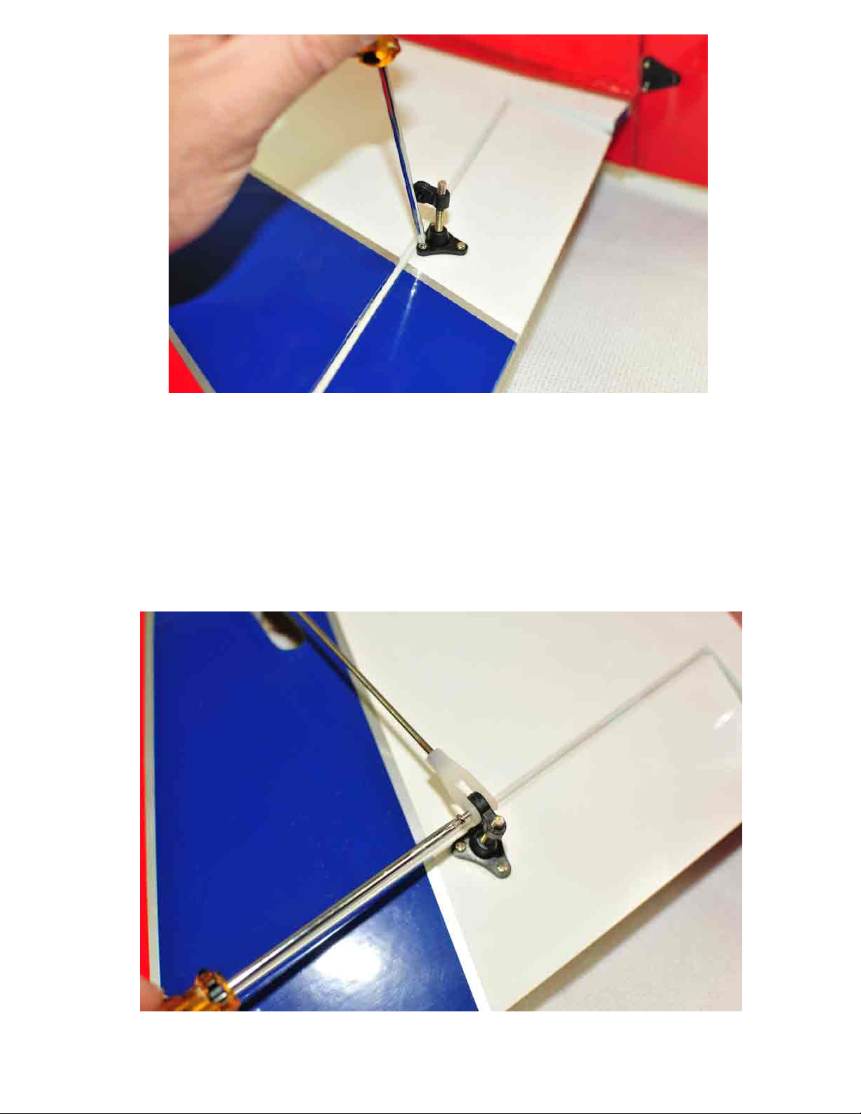
13. Thread a clevis onto one end of the pushrod and a ball link onto the other end.
Secure the clevis to the control horn with the provided screw and secure the ball
link to the servo arm with the 2mm bolt and nut. The distance from the hinge line
to the pivot point should be the same as the distance from the servo output shaft to
the location of the ball link on the servo arm for best mechanical set-up. Screw
the connector down on the threaded horn to the proper position.
13
Page 14

Page 15
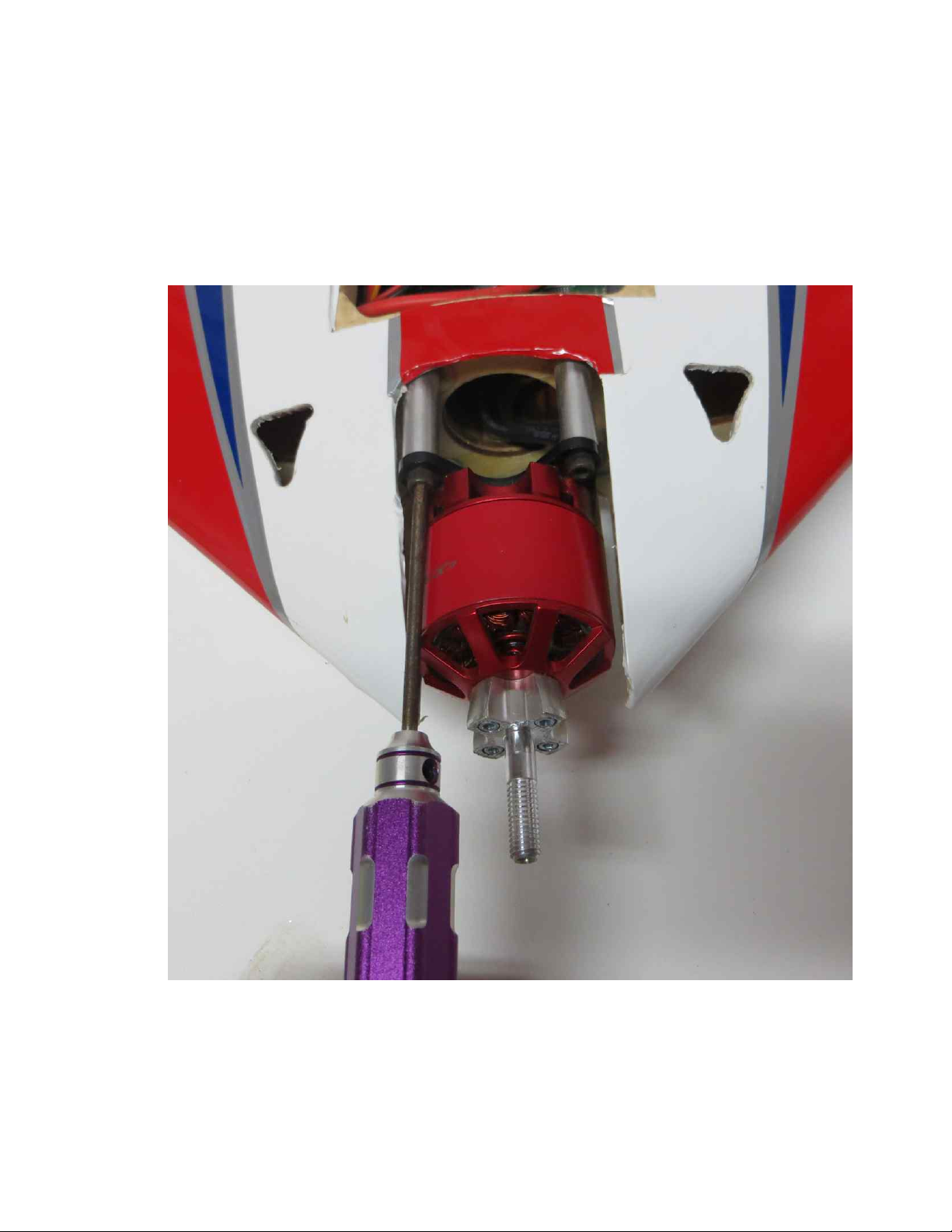
15. Now let's mount the motor. If using the recommended Xpwr T3520 the supplied
aluminum standoffs will make installation a breeze. Other makes of motor may
require different length standoffs. Locate the motor mount package within the
hardware kit which will include 4 long black 3mm socket head cap bolts, 4 nylon
insert locknuts, 4 aluminum standoffs and 4 washers. After mounting the prop
adapter and X mount to the motor (blue Loctite on ALL bolts!) insert the 4 3mm
bolts through the holes in the X mount, through the aluminum standoffs and
through the holes in the firewall. Secure on the back side of the firewall with the
washers and locknuts. It is also a good time to remove the covering from over the
laser cut NACA ducts on each side of the motor compartment.
15
Page 16
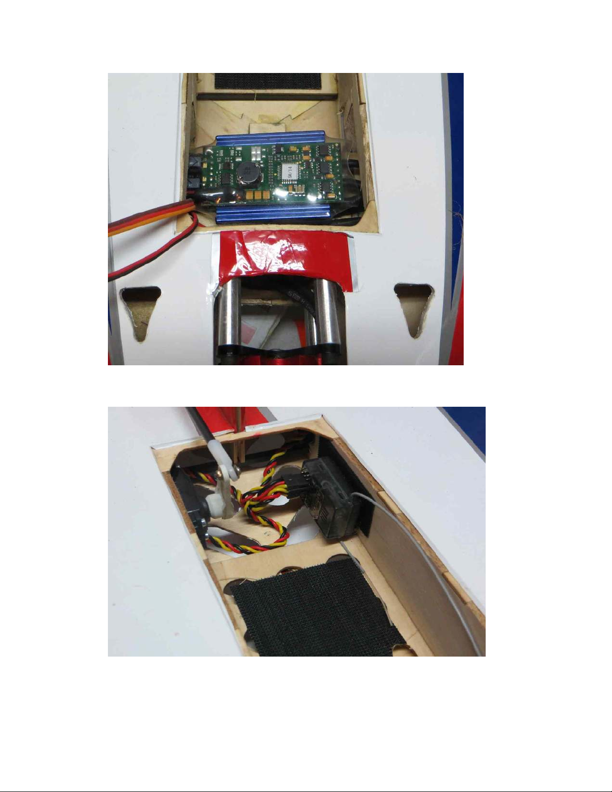
16. Install the ESC on the tray behind the motor with double sided tape or Velcro as
shown.
17. Here is a picture showing where we installed our receiver. There is plenty of
room in the rear of the interior to install your receiver as you see fit.
16
Page 17
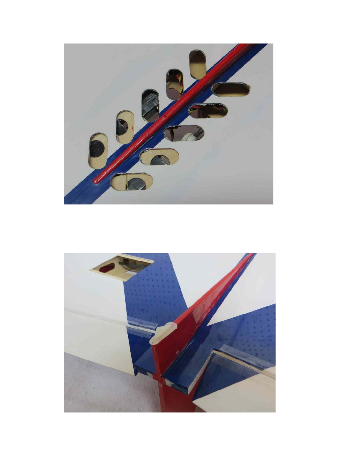
18. Use a sharp hobby knife or soldering iron to remove the covering over the air exit
holes on the bottom of the wing. This is very important to insure proper cooling
of the power system.
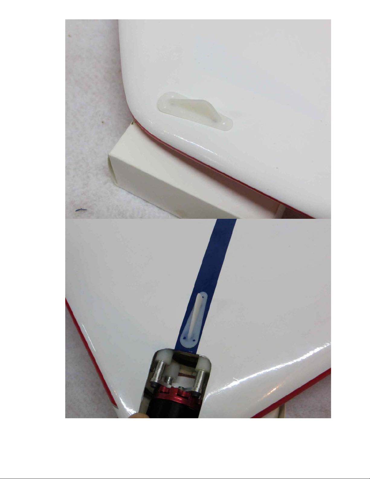
19. There are 4 nylon skids included in the hardware package. These are to be
installed to help protect the bottom of the Outlaw during landing. Please see the
photos below to show where they are to be installed. The smallest of the 3 skids
is to be installed on the bottom of the fin just in front of the rudder hinge line, two
at each wing tip and one just behind the motor compartment as shown. Drill two
holes for each skid to accept the mounting prongs and secure with epoxy.
17
Page 18
18
Page 19

20. Apply a strip of adhesive backed Velcro to the battery tray and secure your
battery with a Velcro strap. Make sure it is secured well!!
This completes the assembly process!
The CG range for the Outlaw is 11.75 inches to 12.25 inches measured forward from
the rear edge of the center fixed portion of the trailing edge of the wing.
Control surface throws are as follows:
Low rate High rate Exponential
Elevons: 15 degrees 45+ degrees 30% low rate 80% high rate
Rudder: 20 degrees 45+ degrees 45% low rate 90% high rate
I highly recommend starting on low rates for the first few flights until you get used to
the aircraft. It is very responsive on high rates and may scare the heck out of you if you
are not prepared! On high rates the roll rate is a blur so make sure you are several
mistakes high when trying out high rates for the first time. To launch, have a friend hold
the Outlaw with both hands at the wing tips and advance the throttle to wide open. Have
your friend push the aircraft forward gently, releasing at about a 25 degree angle. When
the battery is depleted, glide the Outlaw in for a smooth landing, preferably on soft grass.
Thanks again for your purchase of the E-Outlaw ARF! See ya at the flying field!
19
Page 20

20
 Loading...