

Page 1
SE-MANL-BSA2-S1-1IDE-1
User’s Manual
INTRODUCTION
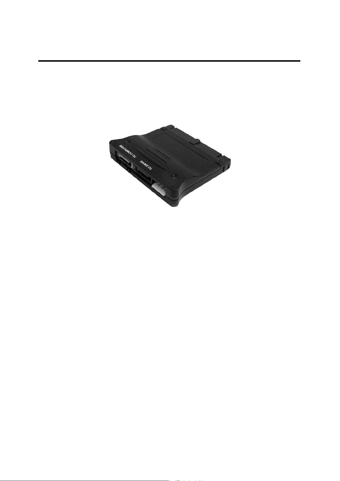
This SATA - IDE Bi-directional adapter is designed for use on any motherboard with one available Serial ATA
(SATA) host port or one available IDE port. With this product, end-user can easily add a SATA device to the
motherboard’s IDE port, or add an IDE device to motherboard’s SATA port. This product complies with
Ultra ATA 133 and SATA 1.0a specificaions and offers superior performance and unmatched data transfer
rates.
FEATURES & SPECIFICATION
General
z Unique bi-directional SATA ÅÆ IDE converter
z Supports 3.5” SATA and IDE (ATA) hard drives
z Supports 5.25” SATA and IDE (ATA) optical drives
z Power-On and HDD-Activity LED indicators
z Ultra low power consumption
z Connectors: one IDE (ATA) connector, one SATA host connector (Yellow), one SATA device
connector (Black) and one 4-pin FDD power connector
z Driverless. No driver is needed
Serial ATA Interface
z Complies with SATA 1.0a specification
z Supports SATA Generation1 transfer rate of 1.5Gbps (150MB/s)
z Supports Spread Spectrum in receiver
z Supports SATA power saving mode: Partial and Slumber
IDE (ATA) Interface
z Complies with ATA specification
z Complies with UltraATA 133 with transfer rate up to 133MB/s
z Supports PIO mode 0, 1, 2, 3, 4, 5, 6, MDMA mode 0, 1, 2 and UltraDMA mode 0, 1, 2, 3, 4, 5, 6
z Supports Master/Slave/Cable Select mode by configuration switches
Package Contents:
z SATA - IDE Bi-directional adapter x 1
z SATA cable x 1
z Small and big 4-pin power extension Y-cable x 1
Page 2

INSTALLATION
Before installing this product, let us make the following assumptions:
End users must have the basic knowledge of installing a device and its software driver to a computer. If
they are not sure about their abilities or have any queries, please call their local dealers immediately, or
find somebody who is experienced and qualified for assistance.
Connecting an IDE Device to the motherboard’s SATA Port:
1. Turn off your computer and all devices connected to it.
2.
Remove the computer’s cover. Refer to your computer user’s manual for more details.
3. Connects your IDE device (such as IDE hard drive or optical drive) to the IDE interface of the product
(Figure 1).
4. Connects the Yellow SATA connector on the adapter to the SATA port on the motherboard using a
SATA cable (Figure 1)
Figure 1:
5. Connect the 4-pin FDD power connector of the product to the motherboard Power Supply Unit (PSU).
If there is no 4-pin FDD power plug available on the PSU, please use the included power extension Ycable to convert the 4-pin HDD power plug to a 4-pin FDD power plug.
IDE Device to motherboard’s SATA Port connection
6. Place the computer’s cover back to the chassis and then turn your computer on.
Connecting a SATA device to the motherboard’s IDE Port:
1. Turn off your computer and all devices connected to it.
2. Remove the computer’s cover. Refer to your computer user’s manual for more details.
Page 3

3. Depending on the existing IDE devices (if any) on your system, follow the direction below to configure
Master/Slave/Cable Select mode of this product (Figure 2).
Figure 2: Master/Slave/Cable Select mode configuration
4. Insert this product into an IDE port on the motherboard (Figure 3).
5. Connect the Black SATA connector on the adapter to the SATA device using a SATA cable (Figure 3).
Figure 3: SATA Device to motherboard’s IDE Port connection
6. Connect the 4-pin FDD power connector of the product to the motherboard Power Supply Unit (PSU).
If there is no 4-pin FDD power plug available on the PSU, please use the included power extension Ycable to convert the 4-pin HDD power plug to a 4-pin FDD power plug
7. Place the computer’s cover back to the chassis and then turn your computer on.
All logos and trademarks referenced are the registered trademark of their respective owners
All specifications and information are subject to change without prior notice
Page 4

FCC Statement:
This equipment has been tested and found to comply with the limits for a Class B digital
device, pursuant to part 15 of the FCC Rules. These limits are designed to provide
reasonable protection against harmful interference in a residential installation. This
equipment generates, uses and can radiate radio frequency energy and, if not installed
and used in accordance with the instructions, may cause harmful interference to radio
communications. However, there is no guarantee that interference will not occur in a
particular installation. If this equipment does cause harmful interference to radio or
television reception, which can be determined by turning the equipment off and on, the
user is encouraged to try to correct the interference by one or more of the following
measures:
—Reorient or relocate the receiving antenna.
—Increase the separation between the equipment and receiver.
—Connect the equipment into an outlet on a circuit different from that to which the
receiver is connected.
—Consult the dealer or an experienced radio/TV technician for help.
Caution: Any changes or modifications not expressly approved by the party responsible
for compliance could void the user's authority to operate the equipment.
 Loading...