

Page 1
Operation
Manual
Catalog #2950
Spectrum
Technologie s, I nc.
Page 2

2
Page 3

Contents
General Overview 4
Initial Startup 5
Connecting to a GPS 6
Keypad Operation 8
Normal Reading Mode 10
Connecting to a Computer 13
Field Scout Software 14
Data Files 16
Identifying the Correct Com Port 17
Light Management 18
Field of View 20
Specifications 21
ERROR messages 22
Frequently Asked Questions 23
Time Zone Corrections 24
Warranty 25
Service and Support 26
3
Page 4

General Overview
The FIELD SCOUT CM1000
senses light at wavelengths of 700 nm and 840 nm to
estimate the quantity of chlorophyll in leaves. The
ambient and reflected light at each wavelength is
measured. Chlorophyll a absorbs 700 nm light and, as a
result, the reflection of that wavelength from the leaf is
reduced compared to the reflected 840 nm light. Light
having a wavelength of 840 nm is unaffected by leaf
chlorophyll content and serves as an indication of how
much light is reflected due to leaf physical characteristics
such as the presence of a waxy or hairy leaf surface.
♦ Lasers define the target as the trigger is pressed. At a
distance of 11.2 inches (28.4 cm), the field of view is
0.434 inches (1.10 cm) in diameter. At a distance of
72 inches (183 cm), the field of view increases to 7.4
inches (18.8 cm) in diameter.
♦ A chlorophyll index value (0 - 999) is calculated from
the measured ambient and reflected light data.
♦ The number of samples taken and a running average
of chlorophyll index values is displayed.
♦ Ambient light level is displayed on a scale of 0 to 9.
♦ The optional data-logging system records the latitude
and longitude (if GPS is used), the sample number,
the individual chlorophyll index reading, and the
value assigned to the ambient light level.
TM
Chlorophyll Meter
♦ The recorded data is downloaded to your PC using
the optional Field Scout
♦ The data-logged files are comma-delimited text files
and can be opened and worked with in any
spreadsheet, graphing, statistical, or word processing
program.
4
TM
software.
Page 5

Initial Startup
Allow the temperature of the CM1000 to equilibrate with
the plant environment prior to sampling. For example,
storing the meter overnight in a freezing tool shed and
then immediately taking readings upon entry into a warm
greenhouse will result in invalid data.
When the CM1000 is first turned on, battery strength
(Battery at __% ) will appear on the LCD. The available
battery power percentage assumes alkaline batteries are
being used. If rechargeable NiCd batteries are installed,
the available battery power will be less than displayed. If
the data logging option has not been enabled, the unit will
then proceed to the normal reading mode.
In order to record data and global positioning system
(GPS) coordinates, the data logger must first be enabled
through the software (See p. 14). If the data logger has
been enabled, battery strength and the amount of
remaining memory (Memory __ % FULL) will be
displayed. If GPS data is being recorded as well, the
meter will display the status of the GPS signal. The meter
will then proceed to the normal reading mode.
IMPORTANT: The GPS unit must be powered up,
have located the satellites and been connected to the meter
before turning the meter on (see Connecting to GPS Unit
p. 6).
5
Page 6

Connecting to a
GPS Unit
The optional data logger function must be enabled using
the Field Scout software in order to record a GPS signal
(see Meter Settings p. 14).
The GPS unit must be plugged into the CM1000 and
working when the meter is first turned on. If a GPS signal
is found at startup, the logger will search for a GPS signal
for every reading. If no GPS signal is found when the
meter is first turned on, the meter will not search for one
when taking readings, thereby saving time when taking
readings. In this case the LCD will display the No GPS
Found message.
For each reading, GPS will be displayed on the bottom
right of the screen. If the GPS signal is lost during a
series of readings, or if the specified differential correction
is lost, the LCD will display LOG rather than GPS in the
lower right corner of the screen. During subsequent
readings, the meter will again search for a GPS signal and
upon finding one, will again display GPS.
GPS Setting
Your GPS unit must be set for NMEA 0183 input/output
messages. If the meter has trouble receiving the GPS
signal, check that the GPS unit has the following settings:
Data bits: 8 Stop bits: 1
Baud rate: 4800 bps Parity: None
Timing: 1 second GGA data string
6
Page 7
Cable Connections
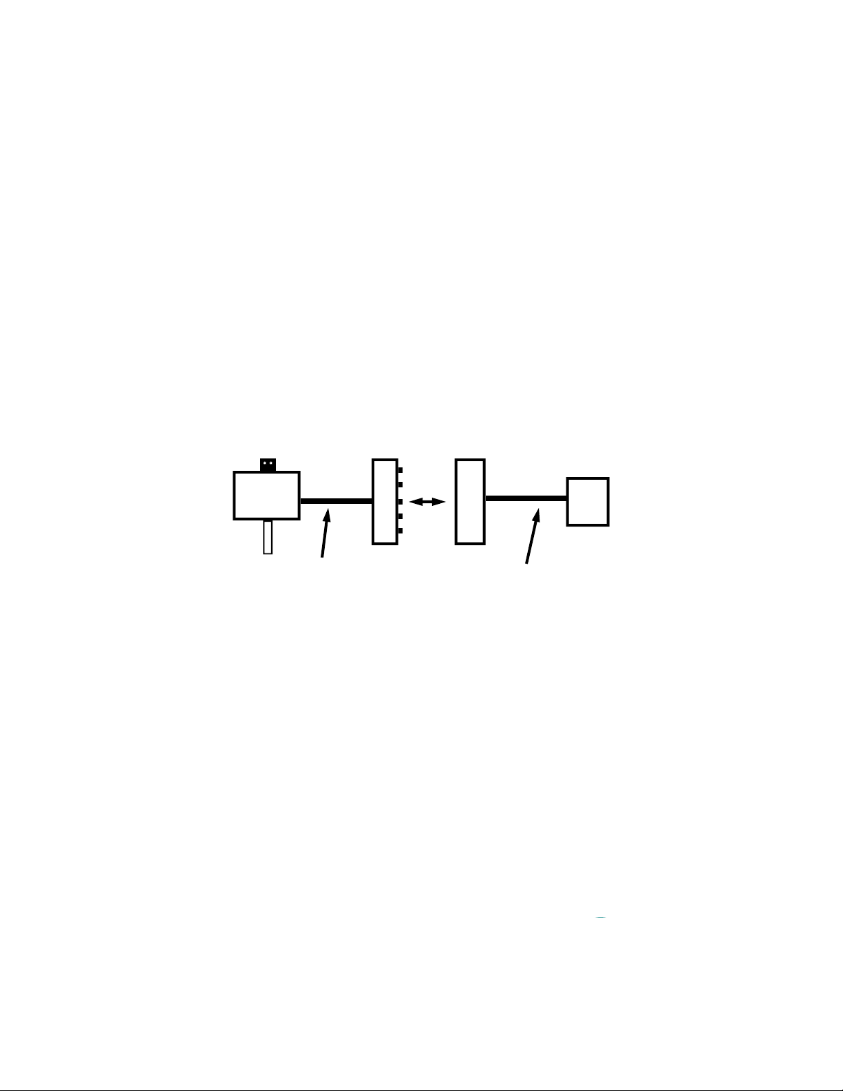
A GPS/DGPS cable (item # 2950CV5) is required to connect the CM 1000 meter to a GPS unit. This cable has a
9-pin male connection and a stereo pin that connects to the
meter’s data port. You will also need a cable that allows
the GPS unit to connect to a 9-pin male serial port. If this
cable doesn’t come standard with your GPS unit, it should
be available from the manufacturer. This cable is generally used to upload information from a computer to the
GPS unit. These components should be connected as
shown in the figure below.
CM1000
Meter
Spectrum
GPS/DGPS
Cable
GPS computer
interface cable
Connecting the CM1000 meter to a GPS unit
GPS
Unit
7
Page 8
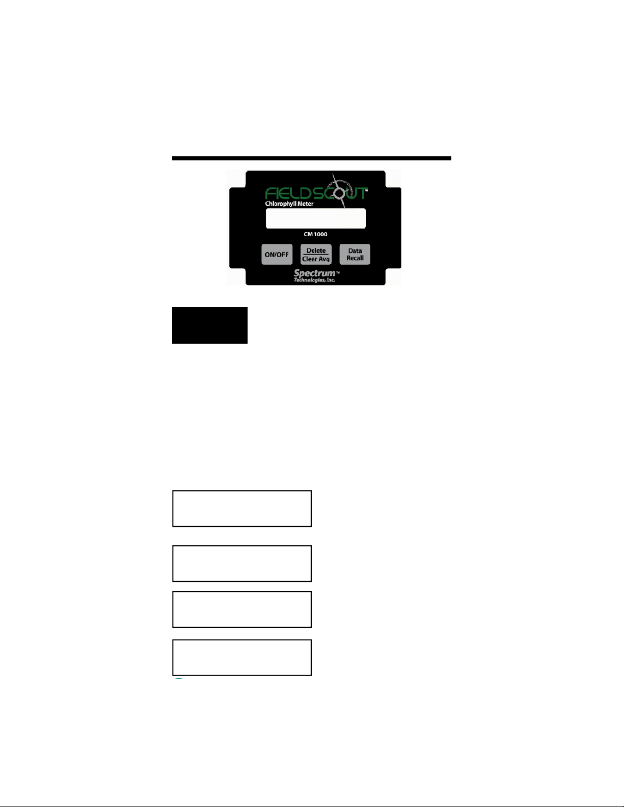
Keypad Operation
ON/OFF
the status of the GPS connection. The meter then goes
into normal reading mode.
CAUTION: If the meter is inactive for 20 minutes, it
will automatically turn off to conserve power. When
the meter is powered off, either with the ON/OFF button or due to inactivity, the AVG and N values are reset to zero (see Normal Reading Mode, p. 10)
BATTERY AT 85%
LOGGER 28% FULL
NO GPS FOUND
LOGGER 35% FULL
GPS=YES DGPS=YES
The ON/OFF button turns the meter on
and off. When the meter is turned on,
it will display the battery status for 3
seconds. The screen will then display
the amount of memory available and
V5.0
Battery status screen
Logger and GPS status
screens
INDEX=275 BRT=4
AVG=283 N015 LOG
8
Data screen
(normal reading mode)
Page 9

As chlorophyll measurements are taken,
Data
Recall
ton was pressed This is separate from the internal data
logger. The readings in short-term memory can be re-
viewed by hitting the Data Recall button. With each
press of the button, the LCD will display the preceding
data point (INDEX and BRT values). The next time the
trigger is pressed, the LCD will revert to normal reading
mode and the current N-value will be displayed along with
an updated Average.
up to 99 readings are stored in the meter’s short-term memory. These will be
the readings taken since meter was
turned on or the Delete/Clear Avg but-
Delete
Clear Avg
running average (AVG) and N-value to zero.
When the DELETE/CLR AVG button is pressed and immediately released, the last data point will be removed from the short-term memory
and the running average. Pressing
and holding this button will reset the
9
Page 10

Normal Reading Mode
Taking Readings
When the meter is on, pressing the trigger on the front of
the handle will activate the targeting lasers and will cause
the measuring and calculating mechanism to become
“Live”. That is, while pulling the trigger, the user can see
the INDEX (see below) being constantly updated as the
targeting lasers are moved around the leaf surface.
Releasing the trigger locks in the INDEX reading and
incorporates that reading into the running average and the
logger’s memory.
NOTE: Readings should be taken only on individual
leaves. Canopy-level measurements are encouraged by
Spectrum Technologies only for fine-textured turf grass.
(See Light Management, p. 18)
When in normal reading mode, the LCD of the CM1000
will display the chlorophyll index value, the brightness
reading from the ambient light sensor, a running average
and indicate whether the data logger is functioning. The
contents of the LCD are explained below.
INDEX
The CM 1000 chlorophyll index reading is reported on a
scale of 0 to 999. The INDEX value is a measure of the
relative greenness of the leaf. This value remains in the
meter’s short-term memory until it is deleted or the meter
is shut off (see Keypad Operation, p. 8). If the data logger
is enabled the INDEX value is also recorded in the
logger’s memory.
10
Page 11

BRT
The response of the ambient light sensor is displayed as a
brightness index value (BRT) from 0 - 9. A BRT value of
one or greater indicates that there are at least 250 to 300
µmol·m-2·s-1 of PAR (photosynthetically active radiation)
light available. This is the minimum light level at which
the meter is useful. At low levels of ambient light, the
index reading may be suspect Full sun should return a
BRT value of seven to eight. Because of the way the
CM1000 estimates chlorophyll content, higher light levels
enable greater resolution in the chlorophyll content
INDEX. (Also see Light Management, p. 18)
NOTE: Excessively bright ambient or reflected light will
saturate the light sensors and thereby cause invalid
readings. When the light sensors near the saturation point,
an LCD message of ERROR, EXCESSIVE LIGHT will
appear.
AVG and N
As each reading is taken, i.e. each time the trigger is
released, the chlorophyll INDEX reading is incorporated
into the running average (AVG) and the sample number
(N) is incremented. The current AVG and N are both
displayed on the bottom line of the LCD.
Although N can increment up to 250, only a maximum of
64 INDEX readings (N064) can be used to generate the
running AVG. If more than 64 readings are taken before
the short-term memory is cleared, the screen will display
AVG=- - -. However, deleting an INDEX reading from
short-term memory (thus causing a new AVG to be
calculated) does not free up memory space for storing an
additional reading. In other words, the average is not
calculated if the trigger has been pressed more than 64
times without clearing the average (see Keypad Operation,
p. 8).
11
Page 12

Valid INDEX readings can be taken beyond the
maximum N value of 250. But N will not continue to
increment unless the entire current data series is cleared,
resetting N to zero.
LOG
The data logger must be enabled in order to download
data to a PC (See Meter Settings, p. 14). The LOG
symbol will be displayed in the lower right corner when
this feature is enabled.
12
Page 13

Connecting to a
Computer
The data port on the underside of the CM 1000 meter can
be accessed by removing the plastic screw. It is through
this port that the meter is connected to either a PC or to a
GPS unit.
Connecting to a PC
The CM 1000 software comes with a gray PC interface
cable. This cable connects to the 9-pin serial port of your
computer and to the meter’s computer port. The meter’s
configuration can be modified by clicking on the Meter
Settings button (see Field Scout Software, p. 14). The
Com Port, Meter Type, Download, Clear Memory and
Meter Settings buttons are also explained in the Field
Scout Software section.
13
Page 14

Field Scout Software
Meter Type
The Field Scout software
supports all of Spectrum
Technologies’ portable data
logging meters. Be sure to
select the CM 1000 Meter
from the Select Meter Type
screen
Com Port
The gray software cable connects
the meter to the computer data
port. The port is located at the
bottom of the meter. Clicking the
Com Port button will bring up the
Port Selection screen. Select the
Com Port that is assigned to the
computer data port. For most machines, this will be COM 1. See
Identifying the Correct Com Port
(p. 7) for instructions on how to
determine which port to select.
Meter Settings
Clicking on the Meter
Settings button will bring
up the Meter Settings
screen. This screen allows you to configure the
meter. The Meter Name
will be the title on the
first line of the
downloaded files.
The logging function is
14
Page 15

enabled by checking the first box in the Logger Settings
section. If the second box in this section is checked, the
logger will store GPS data only if it has been differentially
corrected. If the differential correction is not found, only
the chlorophyll reading will be stored in the data file. A
time zone correction should be entered in the last box.
Time zone corrections for several cities are listed on p. 24.
Download
After clicking the Download button, a progress bar will
confirm that data is being extracted from the
logger. When com-
pleted, the Save Data
As box will appear.
From here you can give
the data file a descriptive name and select a
folder in which to save
it. The folder selection field on the right allows you to
browse to any folder in your system.
When the file has been saved, the software will give you
the option of immediately
viewing the file. The
data file is stored as a
comma-delimited text file
and may be viewed in
any text editor or spreadsheet software.
Clear Memory
Data is not automatically removed from the logger mem-
ory after a download. The Clear Memory button clears
all data from the memory.
15
Page 16

Data Files
Sample data showing results of data collected with and
without GPS activated. Note: GPS signal not found
when recording data in lines 13 and 14.
The data is stored in comma-delimited text files. These
files can be opened with text-editing software (e.g. Microsoft Word) or spreadsheet software (e.g. Excel).
The first two lines of the data file give the logger’s name
and serial number. The third line indicates that latitude
and longitude are referenced to the 1984 World Geodetic
Survey datum. The fourth line shows the column headings for the rest of the data file.
Logging sessions are started and completed by turning the
meter on and off. The start of a logging session is indicated by the data line “Logger Started.” If a GPS signal
was found at the start of a logger session, a time stamp is
included on the “Logger Started” line.
The data is separated into 5 fields: Latitude and Longitude
(blank if a GPS unit was not connected), Sample Number,
Chlorophyll Index Value (on a scale of 0 - 999), and
Brightness.
16
Page 17

Identifying the
Correct Com Port
The computer
Communications Port to
which the PC-3.5 serial
cable is connected can be
identified by using a
paper clip.
1. Disconnect the serial
cable from the meter.
2. To bring up the Port Selection screen, click on the
Com Port Button, select the com port to be tested and
click the Port Test button. Click the Test Port Now
button. If the message “Connection OK” is displayed,
another device (such as a modem) is probably connected
to that port. If the message “No Connection” is displayed,
this port may be the one connected to your serial cable and
you can proceed to the next step.
3. Place a paperclip on the end of the serial pin so that it
touches both the tip of the pin and the metal area between
the two black rings. Again click on the Test Port Now
button. If the message “Connection OK” now appears,
this is the com port connected to your serial cable.
paper clip
or wire
NOTE: The meter does not short-circuit the serial pin.
Therefore, when the Test Port Now button is clicked
while the meter is connected, the “No Connection”
message will be displayed.
17
Page 18

Light Management
Natural sunlight is the best source of light for measuring
chlorophyll by reflectance because both wavelengths are
present in approximately equal quantities and the quantity
of light remains relatively constant. With artificial light
sources, the user must be aware that different light sources
emit light having different qualities. For example,
florescent lights emit more blue light and incandescent
lights emit more red light. The light sensors in the
CM1000 are sensitive enough to detect the cooling of the
filament in an incandescent light bulb as the 120 volt AC
current alternates from positive to negative and back again
at the rate of 60 Hz. The sensitivity of the meter to light
quality enables the meter to estimate the chlorophyll
content of leaves.
When using artificial light, the CM1000 senses light
quantities using a time period that takes into consideration
the 60 Hz alternating current used by electric power
companies in the U.S. The meter must be reconfigured to
be used in Europe and other regions where 50 Hz AC
power is used. Compared to light generated with AC
current, DC light sources provide a steady light output. In
some situations, it may be easier to use a DC light source
than to concern oneself with the frequency qualities of
AC.
It is important to develop a standard method for taking
readings with the CM1000. Ideally, the sun is always at
the user’s back and the line between the sample and the
sensors is approximately parallel to the sun’s rays. The
ambient light sensors are behind the white Teflon dots in
the black rectangular box on top of the yellow case. The
Teflon dots diffuse the ambient light and protect the
ambient light sensors. The user can tilt the black box so
that the ambient light sensors are directly facing the sun,
thereby enhancing the capture of ambient light.
18
Page 19

Like the ambient light sensors, the target leaf should
always be held perpendicular to the sun’s rays to
maximize light reflectance into the meter’s lens from the
leaf surface. All samples must be taken against the same
background. It is preferable to hold the leaf with one’s
hand, not having anything immediately behind the leaf. If
that is not practical, a flat black background should be
used behind the leaf samples. With light-colored or
glossy backgrounds, one may not only be sensing the
reflective properties of the leaf but also the reflective
properties of the background shining through the leaf.
It is preferable to sample with the leaf still attached to the
plant. The effect on light absorption or reflection due to
the extreme water stress of detached leaves is not known.
Canopy-level measurements are recommended by
Spectrum Technologies for fine-textured turf grass only .
When making measurements on turf grass, an adequate
measuring procedure should include having the sun, the
target, and the meter in approximately the same
relationship with each other for each reading. The problem
with trying to measure an entire plant canopy is that not
all leaves in a coarse canopy are exposed to the same
ambient light. Because the light reflected from a canopy
is being reflected in many different directions and that
reflected light is being compared to the available ambient
light, it is absolutely necessary for the both the entire
sample area and the ambient light sensors to be subjected
to the same quantity and quality of light.
19
Page 20

20
This drawing is not to scale.
Page 21

Specifications
Measurement
Sample
Measurement
System
Light Requirements
Measurement
Area
Measurement
Units
Logger Capacity
Repeatability
Weight
Individual plant leaves
turf grass canopy
Reflectance of 700 nm and 840 nm
light
Natural sun light
Artificial light: 60 Hz AC tungsten or
halogen powered by DC current
Contact Spectrum for use with 50 Hz
AC (Europe)
Conical field-of-view between 28.4
and 183 cm
Index of relative chlorophyll content;
0 to 999
3250 readings without GPS/DGPS
1350 readings with GPS/DGPS
± 5% of measurement
1.5 lbs. (0.7 kg)
Temperature
Range
Rod Dimensions
Power
Environmental
Sealing
Operate in 32° to 104° F (0° to 40°C)
Length : 3” (7.6cm), 4.7” (12cm) or
7.9” (20cm)
Diameter: 0.2” (0.5cm)
Spacing: 1.3” (3.3cm)
Two AAA alkaline batteries
Approximately 3000 measurements
Dust-proof
21
Page 22

Error Messages
ERROR Messages
EXCESSIVE
LIGHT
MEMORY FULL
LOW BATTERY
This error occurs when any of the
four light sensors are saturated
due to the ambient or reflected
light being too bright.
This error occurs when the
optional data logger capacity has
been reached. Download the data
and clear the memory.
This error message begins to flash
when the alkaline battery level
reaches 20%. Turn the meter off
and replace the batteries.
22
Page 23

Frequently Asked
Questions
Why doesn’t my CM1000 detect my GPS signal?
The GPS receiver must be turned on and receiving
satellite signals prior to turning on the CM1000.
The data output from the GPS must be specifically
set for NMEA text. This setting is in the GPS
receiver itself, not in the CM1000 meter or software.
I have new batteries. Why doesn’t my initial startup
screen read “Battery at 100%”?
The battery strength indicator is set to accurately
detect the strength of alkaline batteries. The
displayed battery strength of NiCad batteries will be
less than 100%.
Does the CM1000 transmit any signal or light to the
target?
No. The CM1000 only senses the light being
reflected from the target and compares that reflected
light to the ambient light available for reflection.
23
Page 24

Time zone corrections
Time Zone
City
Correction
0 Dublin, Lisbon, London
3 Rio de Janeiro, Montevideo
4 Asuncion
5 Atlanta, Indianapolis, New York, Ottawa, Bogota,
Montreal, Toronto
6 Guatemala City, Houston, New Orleans, Chicago,
Mexico City, Winnipeg
7 Phoenix, Denver, Edmonton
8 San Francisco, Los Angeles, Vancouver
9 Anchorage
10 Honolulu
11 Wellington
13 Adelaide, Melbourne, Sydney
14 Vladivostok, Brisbane
15 Seoul, Tokyo
16 Beijing, Hong Kong, Manila, Singapore, Taipei
17 Hanoi, Jakarta, Vientiane
18 Calcutta, New Delhi
19 Kabul, Islamabad
20 Tehran, Abu Dhabi, Dubai
21 Moscow, Nairobi, Kampala, Riyadh
22 Ankara, Athens, Helsinki, Istanbul, Cairo,
Johannesburg, Harare
23 Amsterdam, Barcelona, Berlin, Geneva, Paris,
Prague, Rome, Brussels, Madrid, Stockholm,
Warsaw, Lagos
24
Page 25

Warr anty
This product is warranted to be free from defects in
material or workmanship for 1 year from the date of
purchase. During the warranty period Spectrum will, at its
option, either repair or replace products that prove to be
defective. This warranty is void if the Spectrum products
have been damaged by customer error or negligence or if
there has been an unauthorized modification.
Returning Products to Spectrum
Before returning a failed unit, you must obtain a Returned
Goods Authorization (RGA) number from Spectrum. You
must ship the product(s), properly packaged against
further damage, back to Spectrum (at your expense) with
the RGA number marked clearly on the outside of the
package. Spectrum is not responsible for any package that
is returned without a valid RGA number or for the loss of
the package by any shipping company.
25
Page 26

Service and Support
The CM1000 is easy to use and reliable. In the unlikely
event that you have a problem with the hardware or
software, please read the following.
Who do I contact?
Contact the company that you bought the CM1000
from: Spectrum Technologies, Inc. or a Spectrum
Authorized Dealer.
When Contacting Spectrum Technologies, Inc.
Please indicate that you need Technical Support for the
CM1000 .
1. Write down the events that led to the problem. Have
you changed anything in your computer recently? Are
you doing anything differently?
2. Provide details on the hardware and software
configuration of your computer including: manufacturer,
model number, peripherals, and versions of the operating
system.
3. Completely describe the problem. The more
information you provide, the faster and more accurately
we will be able to respond.
26
Page 27

27
Page 28

Spectrum
28
Technologie s, I nc.
12360 E. Industrial Dr. East
Plainfield, IL 60585
(800) 248-8873 or (815) 436-4440
FAX: (815) 436-4460
E-Mail: info@specmeters.com
www.specmeters.com
 Loading...