

Spectrum Industries Evolution 38912, Evolution 38916, Evolution 38915, Evolution 38915ADJ, Evolution 38916ADJ Assembly Instructions Manual
...Page 1
Assembly Instructions
Before you begin, please make sure all parts and proper quantities
are included. Any parts damaged during shipment must be reported
within 15 days of receipt. To report information regarding damage, to
purchase parts or accessories, or if you have any questions, please
contact us at:
www.spectrumfurniture.com
715-723-6750, 800-235-1262
Thank you for purchasing Spectrum products!
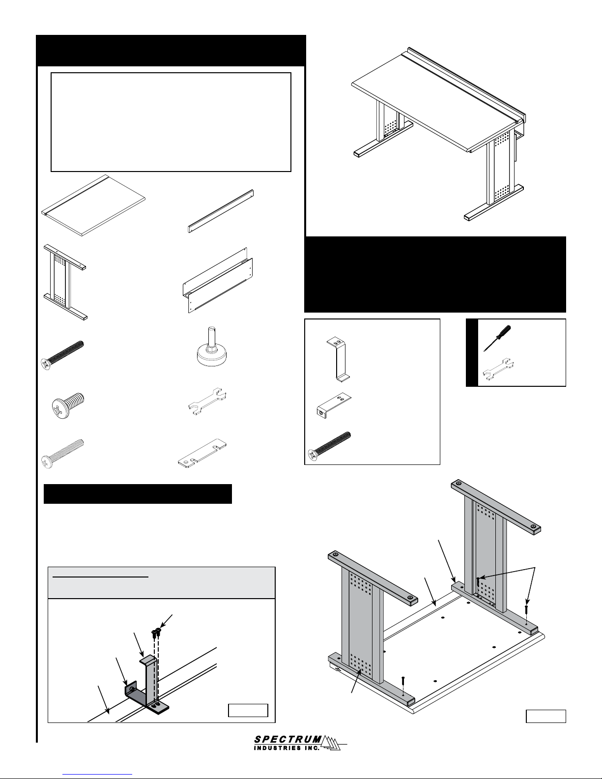
(1) worksurface (1) chair rail
(2) leg
(2) 026011
1/4-20 x 2” FHMS
Important
(1) cord channel /
modesty panel
(4) 025068
5/16-18 x 1” glide
Evolution Desk 24”D
38912 - 36”W
38915 - 60”W
38916 - 72”W
(for 60”, and 72” desks only)
(1) 057922
chair rail bracket #1
38912ADJ - 36”W
38915ADJ - 60”W
38916ADJ - 72”W
Phillips
screwdriver
Tools Required
glide wrench
(10) 1/4-20 x 5/8” PHMS
026064 (black)
043493 (putty)
(4) 041289
1/4-20 x 1-3/4” PHMS
(1) 025069
glide wrench
(2) 052463
unit-to-unit bracket
1. Attach legs to worksurface
1. Place worksurface face down onto a non-abrasive surface.
2. Align the legs with the mounting holes, and install 1/4-20 x 1-3/4” PHM
screws into the legs as shown. Figure 1A.
3. Install 1/4-20 x 1-3/4” PHM screws into the legs as shown, but do not
tighten the screws completely yet.
For 60” & 72” desks only:
Orient and attach the chair rail brackets to the center of the worksurface as shown in Figure 1B with (2) 1/4-20 x 5/8” PHM screws.
1/4-20 x 5/8” PHMS
(2 required)
chair rail bracket #1
chair rail bracket #2
(1) 057890
chair rail bracket #2
(3) 043771
1/4-20 x 2” FHMS
The side of the leg without
the end cap should be
facing the ip-top on the
worksurface
ip-top
worksurface
1/4-20 x 1-3/4”
PHMS
(4 required)
ip-top
worksurface
Figure 1B
The legs should be
attached with the side
panels ush with the legs.
Figure 1A
057859R6 Page 1 of 4
Page 2
2. Install modesty panel / cord channel, and glides
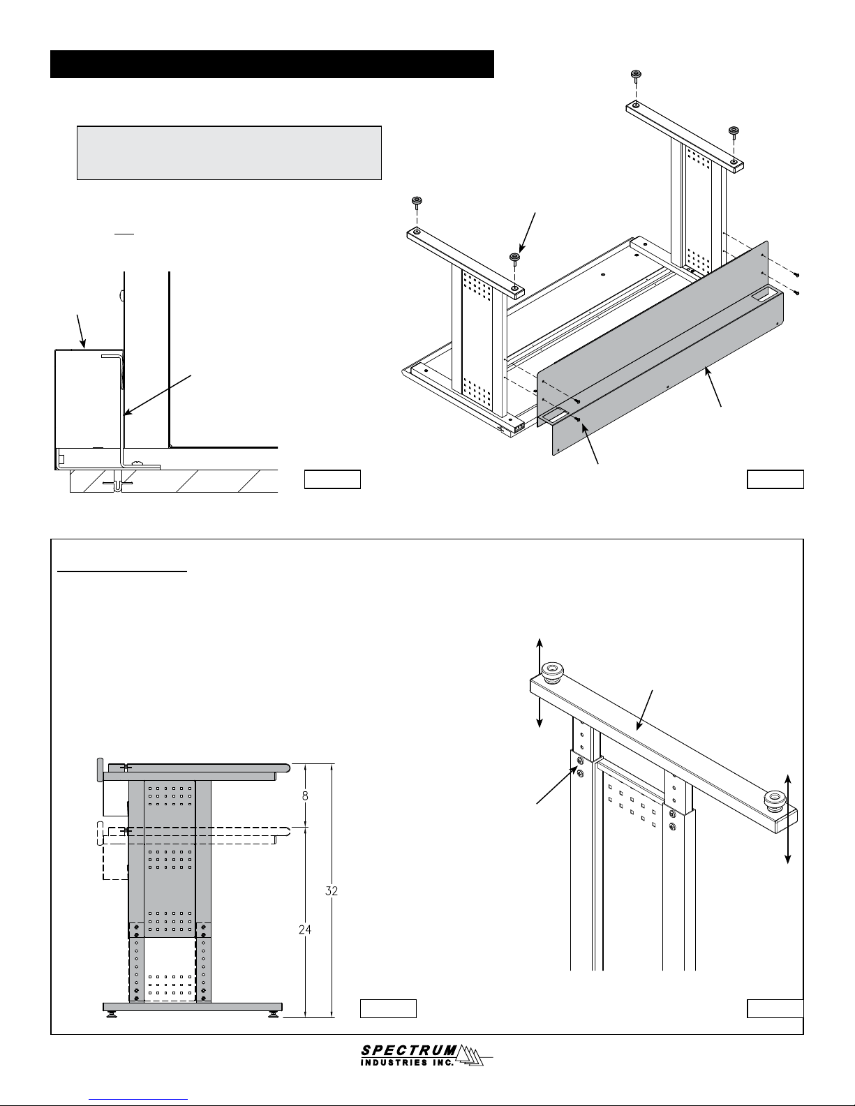
1. Orient the modesty panel/cord channel as shown and attach
to the legs with (4) 1/4-20 x 5/8” PHM screws. Figure 2A.
Note: If you are assembling a 60, or 72” desk, slide the
cord channel over the chair rail brackets. The brackets will
support the inside of the cord channel. Figure 2B.
2. Install the (4) glides to the bottom of the legs. The glides can
be adjusted later to keep the desk level on uneven surfaces.
3. Tighten ALL screws.
cord
channel
chair rail bracket
Figure 2B Figure 2A
Adjustable legs
If you have a desk with the adjustable leg feature, the worksurface height can be adjusted from
24”H - 32”H in 1” increments. Figure 2C. Adjustment is easier if the desk is upside-down.
glides
(4 required)
modesty
panel / cord
channel
1/4-20 x 5/8” PHMS
(4 required)
1. To adjust the legs, remove the (4) pre-installed adjustment screws.
(Fully-support the lower section of the leg while removing). Figure 2D.
2. Choose a height and align the corresponding set of leg holes.
3. Install the (4) previously removed screws in the new holes and tighten securely.
4. Repeat this procedure on the second leg. Make sure to use the same set of holes
used on the rst leg.
Figure 2C Figure 2D
lower section
up to 8” of
adjustment
adjustment
screws
up to 8” of
adjustment
057859R6 Page 2 of 4
Page 3
3. Attach chair rail
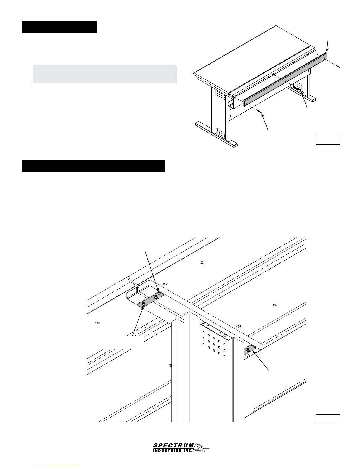
1. Carefully stand the desk upright-this will require at least two people.
2. Attach the chair rail with (2) 1/4-20 x 2” FHM screws as shown. Figure 3.
The chair rail should extend above the worksurface, and the countersunk
holes should be on the outside.
Note: If you are assembling a 60 or 72” desk, attach the center of the
chair rail to the chair rail bracket using the 3rd at head screw.
(The chair rail bracket may require slight adjustment to align properly.)
3. For 60” & 72” desks only: Using the 3rd at head screw, attach the
center of the chair rail to the chair rail bracket. (The chair rail bracket
may require slight adjustment for proper alignment).
4. Tighten all screws securely.
4. Attaching desks together (optional)
Two desks can be attached together with (2) of the included unit-to-unit brackets and
(2) 1/4-20 x 5/8” PHM screws. Figure 4.
1. Locate the desks next to each other in their nal position.
2. Attach one of the unit-to-unit brackets to the back of the legs with (2) 1/4-20 x 5/8”
PHM screws and tighten securely.
3. To attach the front unit-to-unit bracket to the legs, unscrew the existing front leg
screws enough to slide in the bracket, then re-tighten the screws.
1/4-20 x 2” FHMS
(2 required)
chair
rail
for 60”, and 72”
desks only
Figure 3
front unit-to-
unit bracket
desk #1
1/4-20 x 5/8” PHMS
(2 per bracket)
desk #2
rear unit-to-unit
bracket
Figure 4
057859R6 Page 3 of 4
Page 4

Warranty Statement
WE WILL MAKE IT RIGHT FOR YOU!
Spectrum is committed to provide complete customer satisfaction. Each of our products is manufactured from the best materials available and each
product is stringently monitored throughout the production process through our P.A.C.E. program (Product Assurance to meet Customer Expectations).
We expressly warrant that Spectrum products will be of good quality and workmanship and free from defect for the period set out in the warranty table
below from the date of delivery. This warranty shall not apply to defects or damage resulting from misuse, abuse, neglect, improper care, modication
or repair not authorized by Spectrum, or any other cause outside the control of Spectrum. Spectrum will, at its sole option, either repair or replace the
defective product.
This warranty is exclusive; no other warranty, written or oral, is expressed or implied. This warranty is given by Spectrum to Buyer and to no other per-
son or legal entity. No Spectrum dealer, distributor, agent or employee is authorized to make any modication or addition to this warranty.
NOTWITHSTANDING ANYTHING TO THE CONTRARY, SPECTRUM WILL NOT UNDER ANY CIRCUMSTANCES BE LIABLE FOR INDIRECT OR
LIQUIDATED DAMAGES, INCLUDING CONSEQUENTIAL, INCIDENTAL AND SPECIAL DAMAGES. IN NO EVENT SHALL SPECTRUM’S LIABILITY, WHETHER UNDER CONTRACT OR WARRANTY, IN TORT OR OTHERWISE, EXCEED THE PURCHASE PRICE RECEIVED BY SPECTRUM
FOR THE PRODUCT AT ISSUE AND “RECALL ACTION” EXPENSES. SPECTRUM SHALL NOT BE SUBJECT TO ANY OTHER OBLIGATIONS
OR LIABILITIES, WHETHER ARISING OUT OF BREACH OF CONTRACT, WARRANTY, TORT (INCLUDING NEGLIGENCE AND STRICT LIABILITY) OR OTHER THEORIES OF LAW, WITH RESPECT TO PRODUCTS SOLD OR SERVICES RENDERED BY SPECTRUM, OR ANY UNDERTAKINGS, ACTS OR OMISSIONS RELATING THERETO.
Our Customer Service Department is ready to provide immediate attention to any questions, comments or concerns. They are available to answer your calls
Monday through Friday from 7 am to 5 pm CST. In addition your product comments or concerns are welcome via e-mail at: [email protected].
Warranty Table effective 1/1/2015
Item Warranty Period
Adjustable Crank/Electric Desk Legs
Flat Panel Desk Gas Cylinders
Chairs
• Adjustable Height Chair Parts – including frames, gas
cylinders, wood and plastic parts, control handles, casters
• Adjustable Height Chair Upholstery
• In-Stock Upholstery
• Graded-In Fabrics and Customer Owned Material
Height Adjustable Columns and Lifts
General Use Casters
Electrical • 2 Years
Keyboard/Mouse Trays • 1 Year
Flat Panel Monitor Arms
• Flat Panel Monitor Arm – General Parts
• Flat Panel Monitor Arm – Gas Cylinders
Desks and Lecterns
• Computer Desk Chassis
• Cart Chassis
• Lectern Chassis
• 1 Year
• 7 Years
• 2 Years
• 2 Years
• No Warranty
• 1 Year
• 5 Years
• 2 Years
• 10 Years
925 First Avenue, PO Box 400, Chippewa Falls, WI 54729 Ph: 800-235-1262, 715-723-6750 Fax: 800-335-0473, 715-738-2309
E-mail: [email protected] web: www.spectrumfurniture.com
057859R6 Page 4 of 4
 Loading...