

Page 1
Page 2
Headset Feature
The SpectrumPLUSTM is equipped with a
separate port for plugging in an optional
headset. The port is located on the bottom of
the base unit. The TeleMatrix FreeSpeechTM
Talk Feature is a unique TeleMatrix feature that
allows the user the freedom to “toggle” between
the headset, handset and speakerphone modes
during a conversation.
When the “HEADSET ON/OFF” key is ON,
pressing the “SPEAKER” key will activate the
speaker and disconnect the headset line
automatically. This feature avoids ha ving to use
the hook switch/handset to process telephone
calls while in headset mode .
The headset can be purchased from a
TeleMatrix distributor . There are many varieties
of headset models available.
!
LOW VOLT MW
ON OFF
NOTE: An external amplifier is NOT
recommended. The phone has a built
in amplifier.
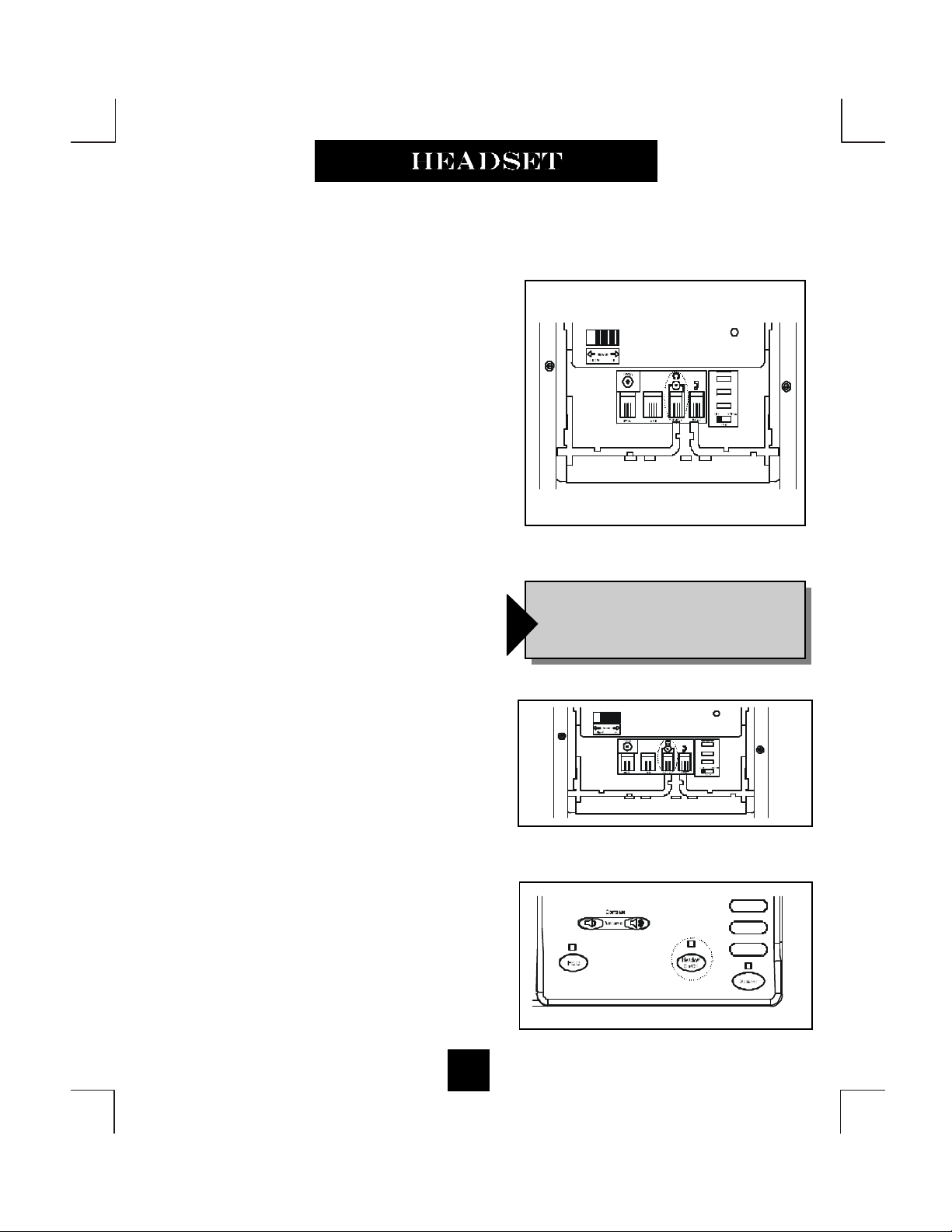
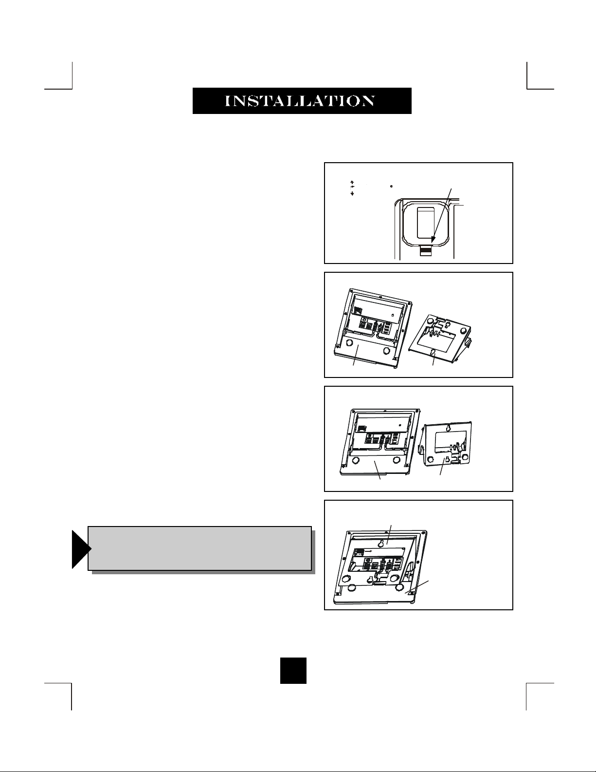
Installing a Headset
? The headset port is located on the bottom
side of the telephone base.
? Plug the modular end of the headset cord
into the modular port of the telephone
labeled “HEADSET” (figure 1).
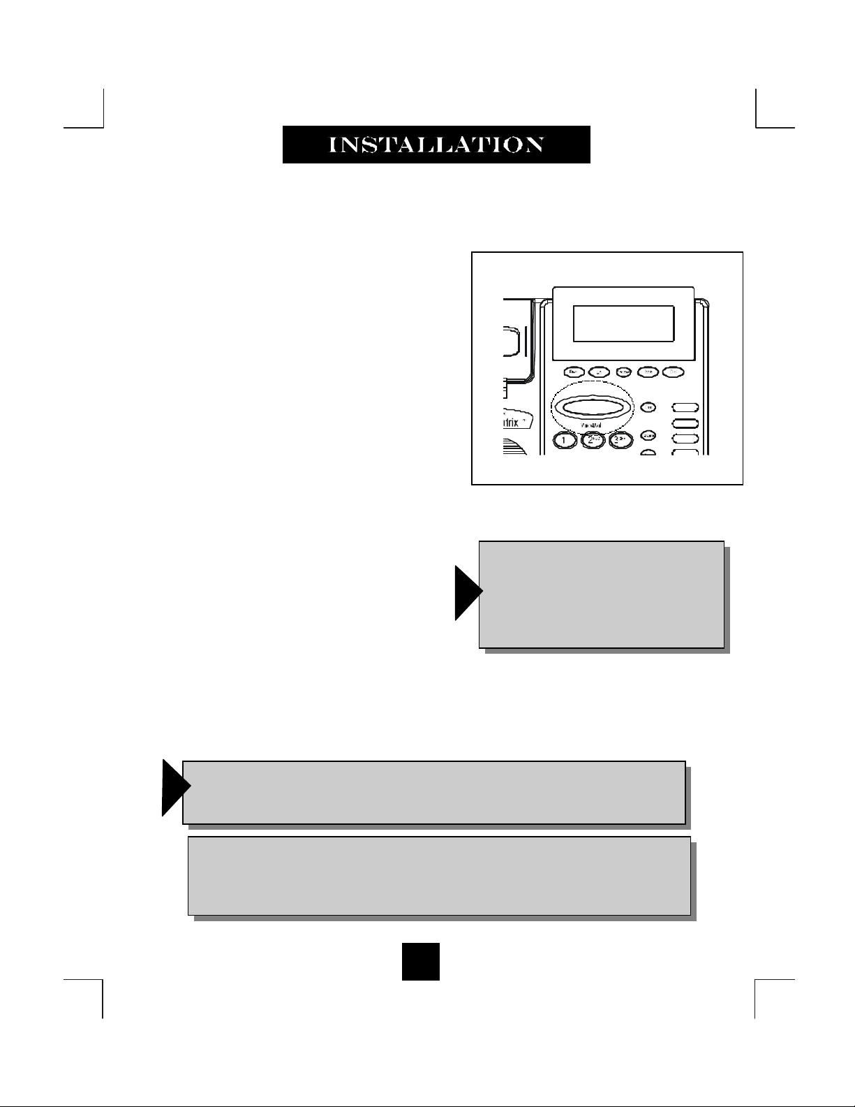
? Press the “HEADSET ON/OFF” key to
activate the headset. The LED above the
key will illuminate to indicate that the
headset is on (figure 2) .
38
LOW VOLT MW
ON OFF
Figure 1
Figure 2
Page 3
Using A Headset
The “HEADSET ON/OFF” key controls the activation of the Headset. When using the
headset feature, the handset remains on-hook at all times.
Placing/Answering a Call
using the Headset On/Off Feature
? To answer an incoming call, press the “HEADSET ON/OFF” key to activate the hea d-
set. The LED above the “HEADSET ON/OFF” key will be illuminated when in ON po-
sition.
? Adjust the volume, if necessary.
? Use the features of the headset that are available with the handset in use.
? You can dial using the the keypad or a speed dial key.
? To end headset activation , press the “HEADSET ON/OFF” key. The LED above the
“HEADSET ON/OFF” key will not be lighted when in OFF position.
Volume Lock Feature — When the handset, speaker, or headset volume feature is
selected, the volume will automatically stay at that setting in the next use.
f
FreeSpeechTM Talk Feature is a unique TeleMatrix feature that allows the user
the freedom to “toggle” between the headset, handset and speakerphone modes
f
during a conversation.
39
Page 4

This page is intentionally left blank
Page 5

Congratulations on the purchase of your TeleMatrix model SP-550 telephone.
The SP-550 includes advanced features that are suitable in today’s business
environment. TeleMatrix has designed the SP-550 to be simple to install and
easy to use. The SP-550 is ideal for use behind Centrex or in a PBX
environment.
The SP-550 telephone is a precision electronic device that requires minimum
maintenance. Please be sure to read the contents set forth in the user’s guide
to become familiar with the wiring and functionality of this product.
a) “This product meets the applicable Industry Canada technical specifications.”
b) “The Ringer Equivalence Number is an indication of the maximum number of
terminals allowed to be connected to a telephone interface. The termination on an
interface may consist of any combination of devices subject only to the requirement that the sum of the Ringer Equivalence Numbers of all the devices does not
exceed five.”
3
Page 6

When using your telephone equipment, basic safety precautions should always be followed to reduce the risk of fire, electric shock and injury to
persons, including the following:
1. Read and understand all instructions.
2. Follow all warnings and instructions marked on the product.
3. Unplug this product from the wall outlet before cleaning. Do not use liquid cleaners or aerosol cleaners. Use a damp cloth for cleaning.
4. Do not use this product near water, for example, near a bath tub, wash bowl, kitchen sink, or laundry tub, in a wet basement, or near a swimming
pool.
5. Do not place this product on an unstable cart, stand, or table. The product may fall, causing serious damage to the product.
6. Slots and openings in the cabinet and the back or bottom are provided for ventilation, to protect it from overheating, these openings must not be
blocked or covered. The openings should never be blocked by placing the product o n the bed, sofa, rug, or other similar surface. This product
should never be placed near or over a radiator or heat register. This product should not be placed in a built-in installation unless proper ventilation
is provided.
IF UNIT IS EQUIPPED WITH POWER ADAPTER:
7. This product should be operated only from the type of power source indicated on the marking label. If you are not sure of the type of power supply
to your home, consult your de aler or local power compan y.
IF ADAPTER IS PROVIDED WITH A GROUNDED TYPE ATTACHMENT PLUG:
8. This product is equipped with a three wire grounding type plug, a plug having a third (grounding) pin. This plug will only fit into a grounding type
power outlet. This is a safety feature. If you are unable to insert the plug into the outlet, contact your electrician to replace your obsolete outlet.
Do not defeat the safety purpose of the grounding type plug.
IF ADAPTER IS PROVIDED WITH A POLARIZED ATTACHMENT PLUG:
This product is equipped with a polarized line plug (a plug having one blade w ider than the other). This plug w ill fit into the power outlet only one
way. This is a safety feature. If you are unable to inset the plug fully into the outlet, try reversing the plug. If the plug should still not fit, contact
your electrician to replace your obsolete outlet. Do not defeat the safety purpose of the polarized plug.
9. Do not allow anything to rest on the power cord. Do not locate this product where the cord will be abused by personswalking on it.
10. Do not overload wall outlets and extension cords as this can result in the risk of fire or electric shock.
11. Never push objects of any kind into this product through cabinet slots as they may touch dangerous voltage points or short out parts that could
result in a risk of fire or electric shock. Never spill liquid of any kind on the product.
12. To reduce the risk of electric shock, do not disasse mble this product, but take it to a qualified serviceman when some servic e or repa ir w ork is
required. Opening or removing covers may expose you to dangerous voltages or other risks. Incorrect re-assembly can cause electric shock when
the appliance is subsequently used.
13. Unplug this product from the wall outlet and refer servicing to qualified service personnel under the following conditions:
A. When the power supply cord or plug is damaged or frayed.
B. If liquid has been spilled into the product.
C. If the product has been exposed to rain or water.
D. If the product does not operate normally by following the operating instructions. Adjust only those co ntrols, that are covered by the operating
instructions because improper adjust me nt of other controls may result in damage and will ofte n require extens ive work by a qualified technic ian to
restore the product to normal operation.
E. If the product has been dropped or the cabinet has been damaged.
F. If the product exhibits a distinct change in performance.
14. Avoid using a telephone (other than a cordless type) during an electrical storm. There may be a remote risk of electrical shock from lightning.
15. Do not use the telephone to report a gas leak in the vicinity of the leak.
IMPORTANT SAFETY INSTRUCTIONS
SAVE THESE INSTRUCTIONS
4
Page 7

FCC Part 15 Compliance
Warning
void the user's authority to operate the equipment.
NOTE: This equipment has been tested and found to comply with the limits for Class B digital device, pursuant to Part
15 of the FCC Rules. These limits are designed to provide reasonable protection against harmful interference in a
residential installation. This equipment generates, uses, and can radiate radio frequency energy and, if not installed
and used in accordance with the instructions, may cause harmful interference to radio communications. However,
there is no guarantee that interference will not occur in a particular installation. If this equipment does cause harmful
interference to radio or television recept ion, which can be det ermined by turning t he equipm ent off and on, the us er is
encouraged to try to correct the interference by one or more of the following measures:
Reorient or relocate the receiving antenna.
Increase the separation between the equipment and receiver.
Connect the equipment into an outlet on a circuit different from that to which the receiver is connected.
Consult the dealer or an experienced radio TV technician for help.
[ The term “IC:” before the cert ification/registration numbe r only signifies that
the Industry Canada technical s pecifications were met. ]
Changes or modifications to this unit not expressly approved by the party responsible for compliance could
Canadian Emissions Compliance
" This digital apparatus does not exceed the Class B limits for radio noise emissions from digit al apparatus set out in
the Radio Interference Regulations of the Canadian Department of Communications. "
"Le present appareil numerique n'emet pas de bruits radiolectriques depassant les limites appli cables auix appareils
numeriques de la class B prescrites dans le Reglement sur le brouillage radioelectrique edicte par le ministere des
Communications du Canada."
5
Page 8

DOC - NOTICE AND LOAD NUMBER STATEMENT
NOTICE: The Canadi an Department of Communica tions label identifi es certified equipm ent. This certification means that the
equipment meets certain telecommunications network protective, operational and safety requirements. The Department does not
guarantee the equipment will operate to the user's satisfaction.
''This product meets the applicable Industry Canada technical specifications.”
Before installin g this equi pm ent, users sh ould en sure that it is permi ssible to b e connec ted to the faci liti es of the loca l telecommunication s company. The eq uipment must also be installed using an acc eptable method of connection. In some cases, the
company’s inside wiring associated with a single line individual service may be extended by means of a certified connector assembly (telep hone exten sion cord ). The cust omer should be aware that complianc e with the ab ove conditi ons may not p revent
degradation of service in some situat ions.
Repairs to c erti fied equ ip ment sh ould b e made b y an aut hori zed Ca nadi an main tena nce fa ci lity desi gnat ed b y the su ppli er. Any
repairs or alterations made by the user to this equipment, or equipment malfunctions, may give the telecommunications company
cause to request the user to d isconnect th e equipment.
Users should ensure for their own protection that the electrical ground connections of the power utility, telephon e lines and internal metallic water pipe system, if present, ar e connected together. This preca ution may be particularly important in rural areas.
Users should not attempt to mak e such connecti ons themselves , but shou ld contact th e appropriat e electric inspection
Caution:
authority, or electrician , as appropriate.
''The Ringer Equivalence Number is an indication of the maximum number of terminals allowed to be connected to a
telephone interface. The termination on an interface may consist of any combination of devices subject only to the requirement that the sum of the Ringer Equivalence Numbers of all the devices does not exceed five.''
[The term “IC:” before the certification/registration number only signifies
that the Indu stry Canada technical specifications were met.]
NOTIFICATION TO THE TELEPHONE COMPANY
Before you may connect your telephone you must notify the telephone company of particular line(s)to which such connections is
to be made, and provided to the telephone company the FCC registration number and ringer equivalen ce number of the registered
protective circuitry. The customer shall give notice to the telephone company upon final disconnection of such equipment or
circuitry from the particular line(s).
Malfunction Of Telephone
In the event that your telephone fails to work properly during your ownership and use of it, you should disconnect it from the
telephone line to determine if it is your phone that is not working properly or if it is a problem in the telephone company's network. If the problem is with your telephone you should discontinue its use until it is repaired.
Telephone Connection Require ments
Except for telephone company- provided ringers, all connections to the telephone network shall be made through standard telephone company provided jacks, in such a manner as to allow for easy and immediate disconnection of the terminal equipment.
Standard jac ks shall be s o arranged that if the p lug connect ed theret o is withd rawn, no inter ference to t he operation of the
equipment at the customer's premises wh ich remains connected to the telephone net work shall occur by reason of such withdrawal. These telephones may not be used on party lines or coin operated lines.
Changes In Telephone Company Equipment Or Facilities
The teleph one c ompany i s enti tled to mak e chan ges in its fac ilit ies equip ment, opera ti ons, and proc edures . Sh ould th ese c han ges
be expected to r ender your t ermin al equipmen t incomp atible wit h the telep hon e company's faci lities you will be given suffi cient
notice to allow you to make the necessary modification to your terminal equipment without any interruption of your service.
6
Page 9

Consumer Information:
This equipment complies with Part 68 of the FCC rules and the requirements adopted by the ACTA. On the bot-
tom of this equipment is a label that contains, among other information, a product identifier in the format
US:2N3MT26B19550 If requested, this number must be provided to the telephone company.
An applicable certification jacks Universal Service Order Codes (USOC) for the equipment is provided (i.e.,
RJ11C) in the packaging with each piece of approved terminal equipment.
A plug and jack used to connect this equipment to the premises wiring and telephone network mu st comply with
the applicable FCC Part 68 rules and requirements adopted by the ACTA. A compliant telephone cord and
modular plug is provided with this product. It is designed to be connected to a compatible modular jack that is
also compliant. See installation instructions for details.
The REN is used to determine the number of devices that may be connected t o a telephone line. Excessive
Ringer Equivalences on a telephone line may result in t he devic es not ringing in response to an incoming call. In
most but not all areas, the sum of Ringer Equivalences should not exceed five (5.0). To be certain of the number
of devices that may be connected to a line, as determined by the total Ringer E quivalences, contact the local
telephone company. [For products approved after July 23, 2001, the Ringer Equivalence for this product is part
of the product identifier that has the format US:2N3MT26B19550 The digits represented by 26 are the Ri nger
Equivalence without a decimal point (e.g., 26 is a REN of 2.6). For earlier products, the Ringer Equivalence is
separately shown on the label.]
If this equipment 19550/195501
advance that temporary discontinuance of service may be required. But if advance notice isn't practical, the telephone company will notify the customer as soon as possible. Also, you will be advised of your right to file a complaint with the FCC if you believe it is necessary.
The telephone company may make changes in its facilities, equipment, operations or procedures that could affect the operation of the equipment. If this happens the telephone company will provide advance notice in order
for you to make necessary modifications to maintain uninterrupted service.
Please follow instructions for repairing if any (e.g. battery replacement section); ot herwise do not alternate or
repair any parts of device except specified.
Connection to party line service is subject to state tariffs. Contact the state public utility commission, public service commission or corporation commission for inform ati on.
This equipment is hearing aid compatible.
NOTICE: If your home has speci ally wired alarm equipm ent connected to th e telephone line, ensure the inst alla-
tion of this [equipment ID] does not disable your alarm equipment. If you have questions about what will disable
alarm equipment, consult your telephone company or a qualified installer.
Should you experience trouble with this equipment, please contact (TeleMatrix, Inc.Customer Care Center 5025
Galley Road Colorado Springs, CO. 80915 . Toll Free:1-800-462-9446 Direct:719-638-8821 Fax:719-6388815 www.telematrixusa.com) for repair or warranty inform ation. If the equipment is causi ng harm to the telephone network, the telephone company may request that you disconnect the equipment until the problem is resolved.
[NOTICE: According to telephone company reports, AC electrical surges, typically resulting from
lightning strikes, are very destructive to telephone equipment connected to AC power sources. To
minimize damage from these types of surges, a surge arrestor is recommended.]
causes harm to the telephone network, the telephone company will notify you in
7
Page 10

Features .........................................………..................................... 9
Controls …….................................................................................. 10
Part List ………………………………………………………….. 14
Installation ....……......................................................................... 15
Wall Mounting .....…..............................……................................ 19
Switch Settings .....….......................….…....................................... 21
Programming ..……..............................…....................................... 22
Headset Installation and Operation……........…............................... 38
LCD Display/Caller Identification …………..…..……………….. 40
Operation …………………………………………………………. 58
Care and Maintenance ……………………………………………. 66
Service ……………………………………………………………. 67
Parts ………………………………………………………………. 68
Warranty ..................................................…...................……........ 69
8
Page 11

• One Line Operation
• SteelTrap
• FreeSpeech
TM
Memory Technology (No Batteries Required)
TM
Talk Feature: Allows Free Toggle between Handset, Headset and Speakerphone.
• Administrator Programming (Fixed): Dialing Access Number, Local Area Code Recognition, Live
Keypad Dialing Option, Restrict 1+ Toll Restriction, 2.0S to 5.0S Pause Timing, 100mS to 1000mS
Flash Timing, Voice Mail Access, and Password Dialing, Speed Dial Programming
• User Programming (Variable): Manual Date and Time, Multiple Language Options, Ring Volume,
Ring Tone Adjustment
• Large, Contrast Adjustable, Backlit LCD Display Shows:
- Programmable Date & Tim e
- Edit Capable Name and Num ber
- Number of New Messag es an d Total Messag es
- Dialing Verificat ion
- Elapsed Call Time r
- Functional Ic ons
- 100 Memory Phonebook w ith A uto Entry from 100 Scrollin g Caller ID C all Records
• Type II C aller ID (C aller ID on C all Waiting)*.
• 100 Name and Number Call Log with Editing, Scrolling, Call Back and Delete
• 100 Name and Number Edit Capable Phonebook
• Visual Message Waiting Indication* – Auto Detection for SDT, FSK, NEON, LED in use switch.
• TouchLite
TM
One Touch Message Retrieval Key
• 2-Way Speakerphone (Half Duplex)
• Headset Port with ON/OFF Sw itch (built-in Amplifier)
• Microphone Mute
• 11 Speed Dial Locations (Administrator controlled)
• Electronic Hold with LED Indicator (optional Standard Line Hold or Programmable System Hold)
• Audible Ring Tone (4 selections)
• Ring Volume Controls (8 selections including OFF)
• Speaker, Headset, and Ringer Volume Soft Key
• Convenient Data P ort
• ADA Compliant Handset with 8-step Volume Control
• Disconnect Key to Activate New Call
• Last Number Redial
• Programmable Flash Key (Admin Programmed between 100mS to 1000mS)
• Programmable Pause Key (Admin Programmed between 1.0S to 5.0S)
• Wall Mount or Desktop Placement
9
Page 12
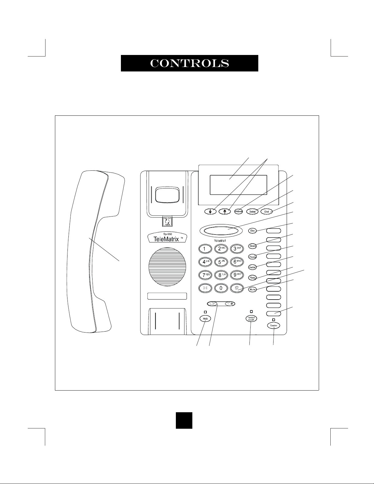
TOP PANEL
(13)
Contrast
Vol um e
(18)
(16)
(19)
(15)
(14)
(17)
(2)
(3)
(4)
(5)
(6)
(7)
(1)
(8)
10
(12)(9)
(10)
(11)
Page 13

1. Speed Dial Feature Keys……………..……… 11 programmable one-touch keys used for speed
dialing.
2. Disconnect Key ……………………...……… Used to disconnect the line, place new call or exit
the store programming.
3. Store Key……………………………….….… Used to program features and speed dialing keys.
4. Pause Key ...............................………...….… Used to program a delay in speed dialing.
5. Redial Key ......................………………….... Redials the last number manually dialed.
6. Flash Key ..................……………..…........… Pr ovides a 100mS to 1000mS timed line break
(programmable).
7. Mute Key …………………………….…….. Disables the handset and sp eaker phone micro-
phones.
8. Numeric Dial Pad ………………...……….. Used for outbound dialing.
9. Hold Key ………………………………..… Lighted key used for placing callers on hold.
10. Headset ON/OFF key ……………………… Lighted key used to turn the headset ON or OFF.
11. Speaker Key .……………….............……… Used to turn the speakerphone ON or OFF.
12. Volume Bar …………………..………….... Adjusts the loudness of the handset receiver, the
headset, and/or speaker.
13. Handset ……………………………….….... Hearing-aid compatible handset.
14. Dial Key ..………................…….....….….… Used to automatically dial the number displayed on
the LCD.
15. Delete Key ……………………………..….. Deletes stored Caller ID records and Phonebook
records.
16. Up and Down Scroll Key ..….........…...…… Used to scroll Caller ID and phone book records.
17. Message Waiting Lamp...…………................ LED indicator that will blink to indicate a new mes-
sage in the user’s voice mail box (user must sub
scribe to a messaging system).
18. LCD Display ...............…….............………... Large adjustable back-lit display that shows Caller
ID, number of calls received, date and time, and
call log
19. Phonebook Key …………………………… Used to access names and numbers in the Phone
book directory.
11
Page 14
BOTTOM PANEL
12
Page 15

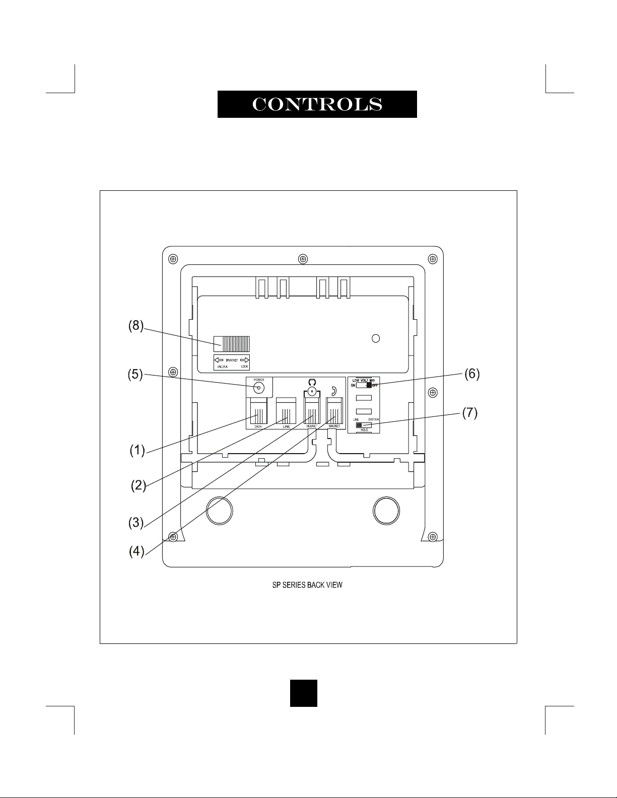
1. Data Port .....................................…...………... Convenient port to connect to a computer,
modem, fax or answering device.
2. Line Jack ……………………………………... Modular receptacle for connecting the line cord.
3. Headset Jack .................................…………… Convenient port for a headset connection.
4. Handset Jack ..................................………….. Connection for handset coil cord.
5. Power Adapter Receptacle ……..…………… For op tional coaxial power adapter.
6. Low Voltage LED Switch ……………...… For optional low voltage LED MW ON or OFF.
7. Hold Key Switch ……………...……………. Used to select standard line hold or
programmable system hold.
8. Elevation Stand Lock ……………………… Used to “lock” the ele vation stand.
13
Page 16
Parts Check List
(7)
(9)
O
U
T
11223344556677889
9
112233445566778899101011
11
2
3. Lift off clear plastic
3
1
Fo
r models SP-100 and SP-200 For model
s with memory: SP-300,SP-400,SP-550,SP-750,S
P-8312
11223344556677889910101111112233445566778899101011
11
1.800.462.9446
Use this perforated sheet to customize your telephone
1. Clear plastic overlay
2
3. Lift off clear plastic
3
1
For models SP-100
and SP-200 For mode
ls
with memo
ry: SP-300
,SP-400,SP-55
0,SP-750,SP-83
12
Volume
Contrast
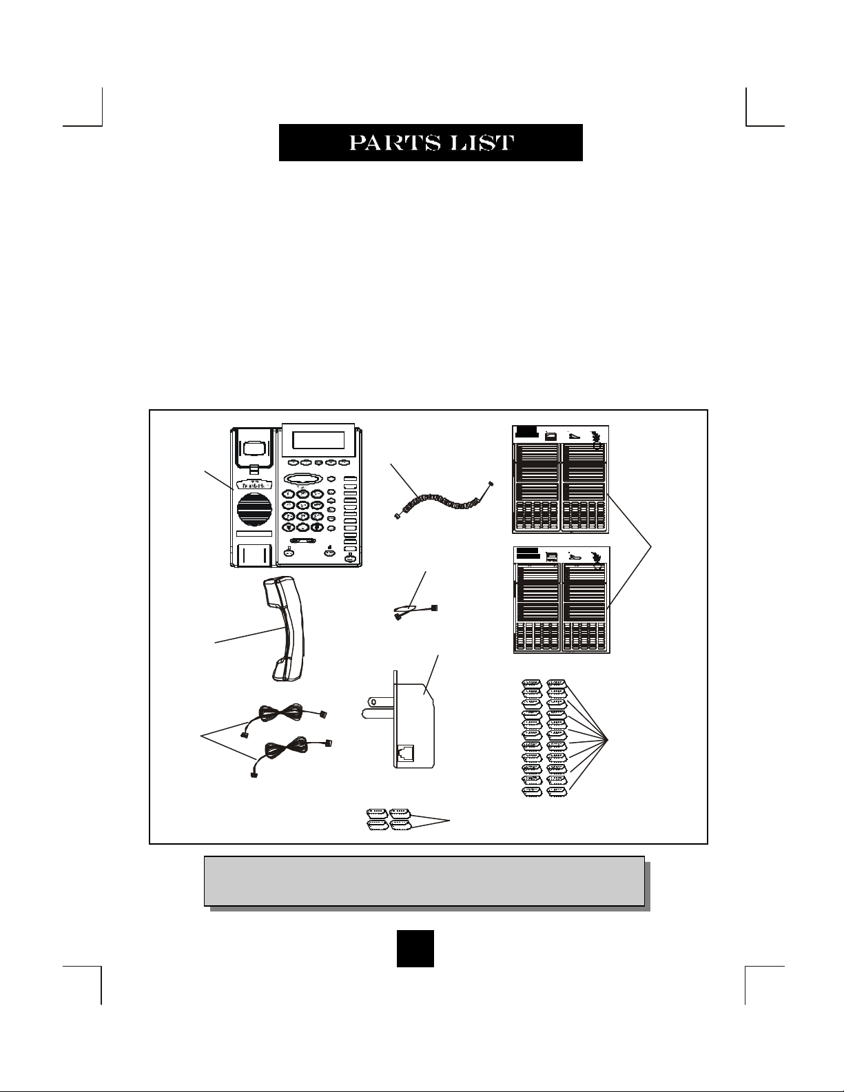
The following parts are included with the SpectrumPLUSTM SP550:
1. Base Unit
2. Handset
3. Two (2) 15 foot Modular telephone line cords.
4. 10 foot Modular coiled handset cord.
5. 6 inch Modular wall mount line cord.
6. Power Adapter.
7. Twenty-two (22) Speed Dial Preprinted Keycaps
8. Four (4) Additional Clear Keycaps
9. Two (2) Index Sheets
1. Clear plastic overlay
being remove from the
index card area on the
telephone.
1.800.462.9446
www.telematrixusa.com
(1)
(4)
(5)
10 10
11 11
www.telematrixusa.com
Use this perforated sheet to customize your telephone
being remove from the
index card area on the
telephone.
2. Tear index paper
from the index sheet.
keycap and insert the
paper key label.
2. Tear index paper
from the index sheet.
keycap and insert the
paper key label.
(2)
(6)
P
H
O
N
E
(3)
(8)
NOTE: SpectrumPLUSTM Line Cords are 6-Pin 6-Conductor Line cords
(6P6C line cord). Replacement Line Cords must be same.
14
Page 17

120V AC Outlet Recovery Power Adapter (provided)
NEL
_
OUT
The 120 VOLT AC OUTLET RECOVERY POWER ADAPTER is an featured TeleMatrix
product. It provides both the telephone lines and the power source in one cable (6P6C line
cord) and is designed to recover the use of the power outlet.
Connector Configuration
The 120V Outlet Recovery Power Adapter has two (2) modular jacks. One jack is labeled
“LINE” and the other jack is labeled “PHONE”. These jacks allow for a fully modular insta llation.
Power Adapter “LINE” Connection
The power adapter “LINE” connection is used
to connect the telephone line from the wall
jack to the power adapter. Using one of the 15
foot modular telephone line cord, connect one
end of the cord to the RJ14 telephone jack on
the wall or base board. The remaining end of
the cord plugs into the “LINE” side of the
power adapter.
L2L1+L2
Power Adapter “PHONE” Connection
The power adapter “PHONE” connection is
used to provide both the telephone lines and
the power source to the telephone. Using one
of the 15 foot modular telephone line cord,
EHNOP
plug one end of the line cord into the back of
the telephone. Plug the remaining end to the
power adapter jack labeled “PHONE”.
ORDER SEPERATELY
16
Page 18
Installing The Wall Power Adapter
POWER
(optional)
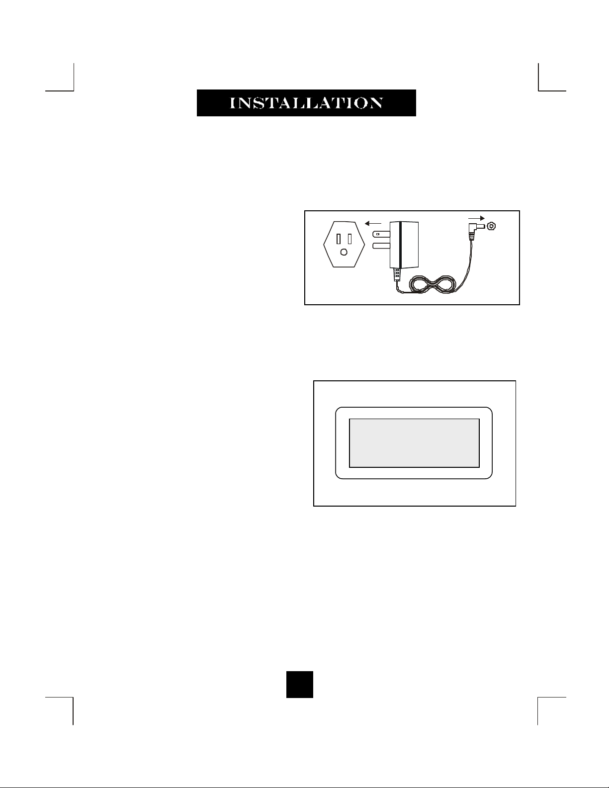
To install, simply plug the power adapter
into a standard 120V AC power outlet. A
mounting hole is provided to secure the
power pack to the AC wall outlet. Plug the
AC power pack directly into the wall outlet
and then plug the coaxial connector into the
receptacle marked “POWER” located on the
back of the telephone.
Completing the Power Installation
If the installation is correct, the information
shown at the right will be displayed on the
LCD.
If the LCD does not display words and
numbers, check your power connections. See
the important note below.
120V AC POWER
ORDER SEPERATELY
02/27 pm12:26
-00- -00-
NEW TOTAL
17
Page 19
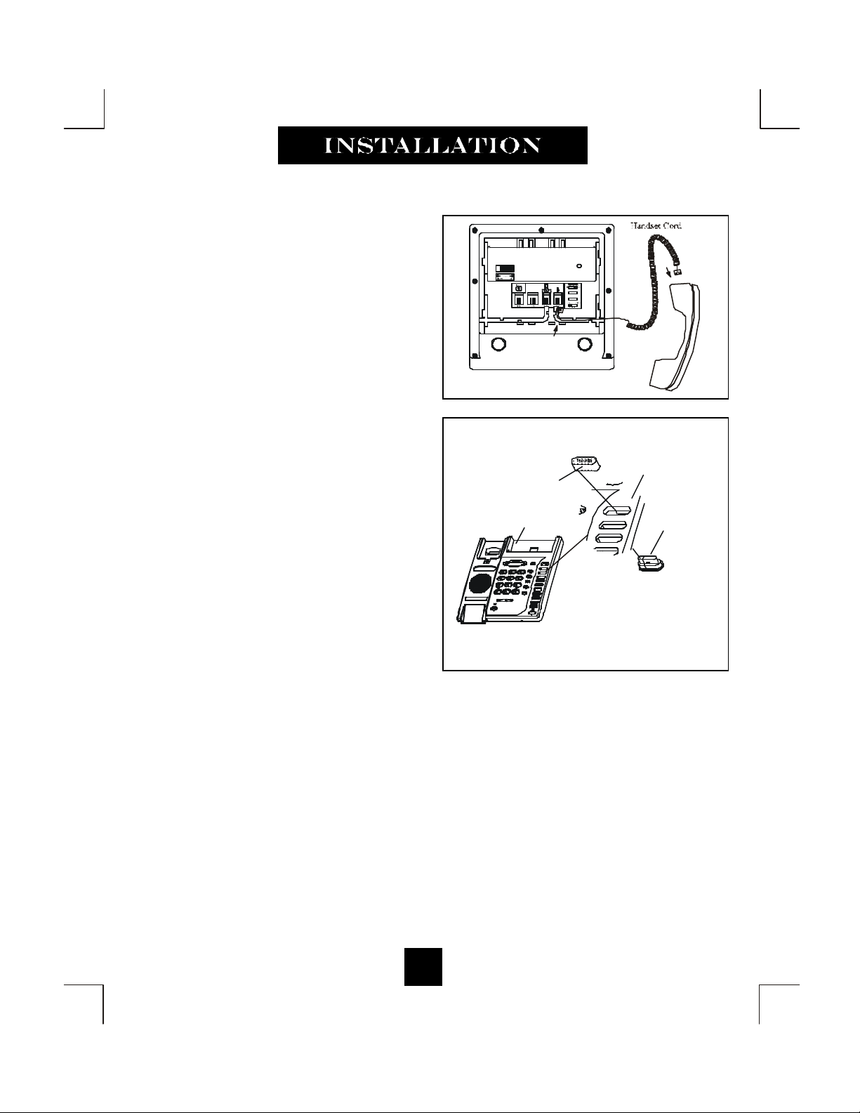
Connecting the Handset Cord
PLASTIC KEYTOP
PLASTIC TOP CABINET
CLEAR "SNAP-ON" KEY CAP
A 10 foot modular coil handset cord is
provided. (Be sure that the wall/desk eleva-
tion stand has not been attached). To install
the cord, simply plug the short end of the
handset cord into the modular jack on the
handset. The long end of the handset cord
plugs into the jack labeled “Handset” located
on the bottom of the SpectrumPLUSTM base
unit. Place the line cord into the line cord
channel located directly below the jack.
Installing the Keycaps
Twenty-two preprinted named feature
keycaps are provided to identify the speed
dial key.
There are 11 clear keycaps already installed.
To install pre-printed keys, remove the clear
keycap by simply pulling up. Replace with
the preprinted keycaps or place hand written
paper index sheets under a clear keycap.
Program each speed dial key for the specific
function of the key.
OR SILK SCREEN KEY CAP
PLASTIC TOP CABINET
For speed dial programming instructions, see the section on “Programming Procedure For
SpectrumPlustm Speed Dial Features” in this manual.
There are 4 additional clear keycaps and 2 index sheets provided as spares. Use these for your
own personal speed dial identities. Write the speed dial name on the blank speed dial index
cards and insert into the blank keycaps. Place the keycap on the correct memory speed dial
location. (see index sheets provided in box) .
The twenty-two preprinted keycaps are described below:
Call Fwd On Call Back Paging Skip Msg Information
Call Fwd Off Cancel Call Back Ring Again FF Msg 911
Transfer Call Park Save Msg Rew Msg
Conf Call Pick-up Del Msg Emergency
DND Group Call Pick-up Rpt Msg Help Desk
18
Page 20
Wall Mounting the SpectrumPLUSTM Telephone
1. UNSNAP
3. SNAP INTO PLACE.
Mounting Wedge
Spectrum Plus Bottom
The SpectrumPLUSTM was designed to be conveniently
wall mounted without requiring additional hardware.
Follow these easy steps:
1.The handset retaining clip must be in the correct
position to secure the handset into the handset cradle.
To engage the clip, pull the clip forward (outward) with
your fingers, rotate the clip 180º and snap the clip back
into place (figure 1). The retaining clip cannot be
removed because it is spring loaded.
2. The SpectrumPLUSTM has provisions for a mounting
wedge that must be correctly positioned. This wedge
allows the telephone to be viewed at a correct angle
when the phone is wall mounted. Remove the wedge
from the phone base (figure 2).
3. Secure the wiring in place prior to installing the wall
mount wedge. The wall mount base has extra large
wiring channels and strain relief poles for containing
the wires in a neat and orderly way. Wrap the wires
around the strain relief poles and then secure the wires
through the channel.
4. To wall mount, place the narrow edge at the top edge
of the phone base and slide the wedge upward into
place (figure 3) .
5. Lock the wall mount into position by sliding the
locking button to the right (figure 4).
Retaining Clip
PULL OUTWARD
2. ROTATE 180 .
Remove Mounting Wedge
Replace Mounting Wedge
Spectrum Plus Bottom
Lock Mounting Wedge
Mounting WedgeSpectrum Plus Bottom
Mounting Wedge
CLIP IS SPRING LOADED
figure 1
figure 2
figure3
Note: A 6 inch line cord is provided for wall mount
installation. Connect one end of the line cord to the
!
phone jack and the oth er end to the wall jack.
Lock mounting wedge
Desk Mounting
To install the wedge for desk mounting, be sure the lock mechanism is positioned to the left clear of the
locking arm. Place the wedge in the slots, wide end toward top of phone base unit, and slide the wedge
upward into position. Lock the wedge into place.
19
figure 4
Page 21
Message Waiting Light Indicator
The SpectrumPLUSTM telephone has a Message
Waiting (MW) Light Indicator (figure 1). The
indicator will blink to indicate that a new message
is in the user’s voice mailbox. The SpectrumPLUSTM supports the following telephone or PBX
supplied message waiting signals:
1. Telephone Company VMWI Service (FSK signal compatible, subscription to local telephone company is required).*
2. Audible Stutter Dial Tone (SDT) signals
provided by local telephone company.
3. 90-Volt NEON message waiting light indicator
signal is provided by your PBX.
4. Low voltage LED message waiting light indicator signal is provide by your PBX.
The PBX system or telephone service provider has
to activate the voice mail feature for the light to
illuminate and work properly. Be sure that your
telephone service provider or PBX system has the
compatible messaging service available in your
area or facility.
!
MW Light Indicator
figure 1
NOTE: The SpectrumPLUS
telephone automatically reads the
Message Waiting (MW) signals
supplied by your service provider.
TM
*Definition: VMWI is Visual Message Waiting Indication. This option requires a
d
subscription to your local telephone service provider for TouchLite
Note: At on-hook status , Press “*” key for 3 to 5 seconds, Message LED will turn
on. At any time press “*” key for 3 to 5 seconds ,Message LED will turn off.
TM
20
to activate.
Page 22

Low Voltage LED Switch
A low voltage LED switch is located on the
bottom of the phone. The switch options are
ON or OFF. The factory default is OFF.
.
System Hold Feature Option Switch
LOW VOLT MW
ON OFF
(Administrator Feature)
A hold feature switch is located on the
bottom of the phone. The switch options are
standard “LINE” hold or programmable*
“SYSTEM” hold.
The standard line hold allows for normal
hold function operation. The programmable*
system hold feature is used for optional
system operations.
The switch default is standard line hold.
LOW VOLT MW
ON OFF
* Programming System Hold is an Administrator function.
To program System Hold, follow the speed dial instructions
in this manual. To store the dialing pattern, press the HOLD
key in place of the memory location.
21
Page 23

Programming Set Up Of the SpectrumPLUSTM Telephone
The SpectrumPLUSTM requires simple initial programming to set up the telephone. The pr ogram is designed for one Administrator and one or more users. Administrator programming
features separate critical operating set up information from the user telephone functions.
The Administrator Quick Program Guide for the SpectrumPLUSTM Telephone
The SpectrumPLUSTM Quick Programming Guide is a summary list of set up options.
Additional detailed instructions are provided in the manual.
Programming is initiated
by holding down the
“STORE” key for six
seconds.
STORE
Set up pre -dialing number
sequence, i.e. outside line.
Set up local area code to
recognize local incoming
calls.
S et up either using keypad
dialing with automatic
speaker activation, or
using key pad dialing,
pressing dial key to act ivate.
Long distance restriction.
Restrict any outgoing
number dialing that begins
with a “1” .
Set up flash timing 100mS
to 1000mS. Default
Set up pause timing 1.0S
to 5.0S. Default 3.6S.
ENTER ACCESS NO.
ENTER AREA CODE
LIVE DIALPAD XXX
PRESS 1=ON 2= OFF
RESTRICT 1+
PRESS 1=YES 2= NO
FLASH TIME SET
PAUSE TIME x.x S
VOICE MAIL NO.
PIN NUMBER
SECOND OF WAIT?
ALL SETUP OK
S et up voice mail
number. Add your
PIN with seconds of
wait time to get
access to messages.
PIN number chara cters will not be
displayed
Between voice mail
number and pin
number waiting
time default 0S
22
Page 24

Programming Set Up of the SpectrumPLUSTM Telephone
The SpectrumPLUSTM requires simple initial programming to set up the telephone. The program
is designed for one Administrator and one or more users. Administrator programming features
separate critical operating set up information from the user telephone functions.
The Users Quick Program Guide for the SpectrumPLUSTM Telephone
The SpectrumPLUSTM Quick Programming Guide is a summary list of set up options.
Additional detailed instructions are provided in the manual.
Programming is initiated
by quickly pressing the
“STORE” key.
Set up date and time
Set up language
Set up ringing options of
ring tone (4 tones) and ring
volume (8 steps). Press
keypad number for sample
of ringing tone or vol ume.
STORE
SETUP MONTH:01
SETUP DAY:01
SETUP TIME MODE
PRESS 1=12 2=24
AM=1 PM=2
SETUP HOUR:01
SETUP MINUTE:01
-1- -2- -3-
ENG FRA ESP
RING TONE 1- - 4
Note: the date and time
will automatically set if
your telephone line is
equipped with Caller ID.
The date and time will be
set by an incoming ring.
Set up is complete.
RING VOLUME 1- - 8
ALL SETUP OK
23
Page 25

S et up using keypad dialing with automatic
speaker activation or
using key pad dialing and
pressing dial key to act ivate.
Display indicates condition of ON or OFF, then next screen a p-
12/01 PM 12:00
LIVE DIALPAD ON
12/01 PM 12:00
PRESS 1=ON 2=OFF
LIVE DIALPAD XXX
PRESS 1=ON 2= OFF
Live Dialpad Feature
(Administrator Programmable Only)
This feature allows the Administrator to set
up the telephone keypad ON HOOK dia ling method.
When LIVE DIALPAD is OFF, and the
handset is ON HOOK, the user enters a
number on the keypad must then press the
“DIAL” key to activate dial tone.
When LIVE DIALPAD is ON, and the
handset is ON HOOK, the dial tone activates immediately upon pressing the keypad.
The handset can be lifted at any time to acti vate the receiver.
To enable or disable LIVE DIALPAD ON.
1. Press and hold the “STORE” key for
6 seconds.
2. Press “STORE” multiple times until
the LCD displays “LIVE DIALPAD
ON”.
3. Press “1=ON” to enable, or “2=OFF”
to disable.
4. To exit the program mode, press
“DISC” or continue to the end of programming by pressing the “STORE”
key multiple times until the display
reads “All Setup OK”.
Note: Programming can
only be performed when
!
phone is on-hook
NOTE: The Live Dialpad feature works only when the
handset is ON HOOK, it does not work when the handset
!
is OFF HOOK.
24
Page 26

Long distance restriction.
Restrict any outgoing
number dialing that begins
with a “1” .
12/01 PM 12:00
RESTRICT: 1+
Note: Programming can
only be performed when
!
phone is on-hook
RESTRICT 1+
PRESS 1=ON 2= OFF
Restrict 1+ Feature
(Administrator Programmable Only)
This feature allows the Administrator to
restrict the use of 1+ long distance calling.
To enable RESTRICT 1+.
1. Press and hold the “STORE” key
for 6 seconds.
2. Press “STORE” multiple times until
the LCD displays “RESTRICT 1+”.
3. The display will read “ PRESS 1 =
YES 2 = NO”
4. To enable restriction, press “1” on
the keypad.
5. To disable restriction, press “2” on
the keypad.
6. To exit the program mode, press
“DISC” or continue to the end of
programming by pressing the
“STORE” key multiple times until
the display reads “All Setup OK”.
Note: With 1+ Restrict Dialing,
the user cannot dial any number
!
beginning with a 1.
25
Page 27

Programming Flash Timing into Memory
(Administrator Programmable Only)
Flash Timing can be programmed into the SpectrumPLUSTM speed dial memory. This function allows the user to include a timed line break in the sequence of the dialing patterns when
using the speed dial keys . This function may be required for accessing line features provided
by your telephone system or local telephone company. The flash timing options are 100
through 1000 milliseconds, programmable in 100mS increments.
Set up flash timing 100mS
to 1000mS. Default 600mS.
FLASH TIME SET
12/01 PM 12:00
600
FLASH TIME SET
Using A Flash When Dialing
To use a Flash when dialing, simply press the “FLASH” key at the appropriate point in the
number sequence being dialed from the key pad.
NOTE: Each “Flash” function counts as 1 digit when stored into a speed dial memory location
!
26
Page 28

Programming Flash Timing
(Administrator Programmable Only)
Flash timing can be programmed for different timing options listed below.
1. Press and hold the “STORE” key for 6 seconds to enter set up.
2. Press the “STORE” key multiple times until the LCD display reads “FLASH TIME SET”.
3. Enter the flash timing to be stored into memory using the keypad by pressing the following
keys on the keypad in the order shown. The keypad entry will be displayed on the LCD
Screen.
For 100mS press "1" "0" "0" on the keypad.
For 200mS press "2" "0" "0" on the keypad.
For 300mS press "3" "0" "0" on the keypad.
For 400mS press "4" "0" "0" on the keypad.
For 500mS press "5" "0" "0" on the keypad.
For 600mS press "6" "0" "0" on the keypad.
For 700mS press "7" "0" "0" on the keypad.
For 800mS press "8" "0" "0" on the keypad.
For 900mS press "9" "0" "0" on the keypad.
For 1000mS press "1" "0" "0" "0" on the keypad.
4. To exit the program mode, press “DISC” or continue to the end of programming by
pressing the “STORE” key multiple times until the display reads “All Setup OK”.
5. To confirm the flash timing programmed in memory, repeat the Administrator programming
sequence to see flash timing display.
Programming Example for 100mS
Press “STORE” for 6 seconds, Press “STORE” again until LCD
reads “ “FLASH TIME SET”. Enter digits “100” from the keypad.
Press “STORE” to enter the timing into memory.
Note: Programming can
only be performed when
!
phone is on-hook
NOTE: The Flash Timing factory default is 600mS !
27
Page 29

Programming Pause Timing
(Administrator Programmable Only)
A Pause time between 2.0S to 5.0S can be programmed into memory at the option of the Administrator. This function allows the Administrator to provide delay timing for systems requiring different delay times and the user to delay the dialing pattern of a number. This function
may be required for accessing line features provided by telephone provider or local telephone
company. A speed dial number may need to pause during its dialing sequence to ensure proper
connections.
Set up pause timing 1.0S to
5.0S. Default 3.6S.
PAUSE TIME x.xS
12/01 PM 12:00
PAUSE TIME:3.6S
Pause timing can be programmed for different timing options listed below.
1. Press and hold the “STORE” key for 6 seconds to enter set up.
2. Press the “STORE” key multiple times until the LCD display reads “PAUSE TIME:3.6S”.
3. Enter the pause timing to be stored into memory using the keypad by pressing the following
keys on the keypad in the order shown. The keypad entry will be displayed on the LCD
Screen.
Four Examples:
For 2.0S press "2" "0" on the keypad.
For 2.1S press "2" "1" on the keypad.
For 3.2S press "3" "2" on the keypad.
For 4.9S press "4" "9" on the keypad.
4. Press the “STORE” key to enter the new pause timing value.
5. To exit the program mode, press “DISC” or continue to the end of programming by
pressing the “STORE” key multiple times until the display reads “All Setup OK”.
NOTE: If you require a pause time delay longer than the maximum setting of 5.0S,
stack the pauses within the dialing pattern to achieve the longer timing. !
28
Page 30

Programming a Pause into Speed Dial Memory
(Administrator Programmable Only)
Pause(s) can be programmed into the speed dial memory at the option of the Administrator.
This function puts a delay the dialing pattern of a number. Multiple pauses can be programmed into speed dial for added pause time.
To Program A Timed Pause
1. To store a Pause into Speed Dial memory,
simply press the “PAUSE” key in the nu mbering sequence when programming speed
dial memory keys.
2. See page 34 for programming speed dial.
!
NOTE: The default Pause timing is 3.6 Seconds.
A multiple of Pauses can be programmed
into speed dial memory to increase the delay.
Note: Programming can
only be performed when
!
phone is on-hook
Using a Pause when Dialing
To use a Pause when dialing, simply press the “PAUSE” key at the appropriate point in the
number sequence being dialed from the key pad.
!
NOTE: Each “Pause” function counts as 1 digit when stored into a speed dial memory
29
Page 31

Programming the Access Number into Memory
(Administrator Programmable Only)
In some cases, a digit or digits are required to access an outside line (i.e. 9) . The Access Number
can be programmed into the phone memory at the option of the Administrator. This function allows
the user to automatically dial number(s) that are required prior to dialing the displayed number.
? The numbe r to be programmed is based on your specific area dialing requirements
and may not be required.
? This option is not mandatory for the proper operation of the Caller ID display.
Set up pre-dialing number
sequence, i.e. outside line.
Note: Programming can
only be performed when
!
phone is on-hook
ENTER ACCESS NO
12/01 PM 12:00
9 - - - -
ENTER ACCESS NO.
To Set Up The Access Number
1. Press and hold the “STORE” key for six seconds to enter programming.
2. Press “STORE” until the LCD display reads “ENTER ACCESS NUMBER”.
3. Enter the desired number, for example, a “9”.
4. Press the “STORE” key to enter the number into memory.
NOTE: There is no need to enter PAUSE. The Call Back operation
!
automatically inserts a pause after the Access Code Number.
To Delete The Access Code
1. Press and hold the “STORE” key for six seconds to enter programming.
2. Press the “STORE” key until the LCD display reads “ENTER ACCESS NUMBER”.
3. Press the “DELETE” key.
4. Press the “STORE” key again to continue.
30
Page 32

Programming the Area Code into Memory
(Administrator Programmable Only)
An Area Code can be programmed into the phone memory at the option of the Administrator.
The Area Code is programmed into memory to allow the phone to recognize the local area code.
When this number is programmed, the Area Code WILL NOT be dialed when calling back a
number within the same local calling area.
Set up local area code to
recognize local incoming
calls.
ENTER AREA CODE
12/01 PM 12:00
719 - -
ENTER AREA CODE
Programming the Area Code into Memory
1. Press and hold the “STORE” key for 6 seconds to enter programming
2. Press the “STORE” key multiple times until “ENTER AREA CODE” is displayed.
3. Enter the area code number of the local area code using the numeric dial pad.
4. Press the “STORE” key to store the area code into memory.
5. To exit the program mode, press “DISC” or continue to the end of programming by pressing the “STORE” key multiple times until the display reads “All Setup OK”.
In some areas, the Area Code is required when placing a Local Call
In some areas, the local service provider will use the same area code for local calls. The follo wing options are available.
Try each of the following scenarios and use the one with the best result.
1. Program the Area Code first, then place a local test call.
2. Delete the area code and do not program the Access Code. Place a local test call.
3. Program the Area Code into the Access Code location. Place a local test call.
4. Use the keypad to add additional numbers to the displayed number on the screen. Place a
local test call.
NOTE: Depending on your area and dialing pattern, you may obtain the best result by using both the access code and area code fields. If these sequences do not work, use the keypad entry as an option for your
!
Call Back.
31
Page 33

Programming Voice Mail
(Administrator Programmable Only)
Voice Mail (VM) access numbers and their associated “Personal Identification Number” (PIN)
can be programmed into phone memory when Voice Mail is activated. The feature allows the
user to automatically obtain their voice mail using the SpectrumPLUSTM TouchLiteR speed dial
key.
VOICE MAIL NO.
PIN NUMBER
SECOND OF WAIT?
Note: Programming can
only be performed when
!
phone is on-hook
Add the Voice Mail
number to dial. Add users
PIN. Add seconds of wait
time to delay access until
Telco introduction message
is complete.
Note: PIN characters will
not be displayed on the
LCD.
12/01 PM
5551212
VOICE MAIL NO.
12/01 PM
- - - - - - - -
PIN NUMBER
12/01 PM
05
SECOND OF WAIT?
32
Page 34

Programming Voice Mail
(Administrator Programmable Only)
To program the SpectrumPLUSTM one touch “MESSAGE WAITING” speed dial key, follow
these programming instructions.
Programming Voice Mail Dialing
1. Press and hold the “STORE” key to activate
Administrator mode.
2. Press the “STORE” key multiple times until
“VOICE MAIL NO.” is displayed on the LCD
screen.
3. Enter the voice mail number. The area code is
not required if AREA CODE is programmed
into memory.
4. Press the “STORE” key to store the voice mail
number into the VOICE MAIL memory key.
5. Enter the “PIN NUMBER”, up to 8 digits. The
PIN characters will not be displayed.
6. Enter the “SECONDS OF WAIT?”, up to 99
seconds.
7. To exit the program mode, press “DISC” or
continue to the end of programming by pressing
the “STORE” key multiple times until the display reads “All Setup OK”.
Test the program
After programming voice mail, test the program by
placing a voice mail into the vo ice mail messaging
system. Then, press the key located on the base unit
(when in OFF HOOK position) and dial the preprogrammed numbering sequence. The “SECONDS
OF WAIT” may need to be increased if the voice
mail was not retrieved.
12/01 PM 12:00
555-1212
VOICE MAIL NO.
12/01 PM 12:00
- - - - - - - -
PIN NUMBER
12/01 PM 12:00
05
SECOND OF WAIT?
33
Page 35

Programming Procedure for SpectrumPlustm Speed Dial Features
(Administrator Programmable Only) (Manual Entry of Characters)
The SpectrumPLUSTM Telephone has 11 one -touch speed dial locations that are convenient for
dialing frequently used telephone numbers. This feature is under Administrative control so user
changes do not occur.
? Speed dial programming must be done with the telephone plugged into the telephone line and power
adapter.
? Programming can be per formed with the telephone on-hook only.
? A maximum of 32 digits can be entered into ENTER NUMBER and 12 characters into ENTER
NAME.
ENTER NUMBER
ENTER NAME
To Program Speed Dial Locations
Set up speed dial memory
locations with name and
number entries. Check
verifies correct entry.
1. Press and hold the “STORE” key for 6 seconds to
activate Administrator mode. The words “ENTER
ACCESS NO.” will appear (figure 1).
2. Next, press the speed dial location key where the
desired location will be. The display will read
“Mxx NO CONTENT”. If the display shows a
record, then there is a stored name and number in
that location (figure 2) .
3. Press the “STORE” key again and the display will
read “ENTER NUMBER” (figure 3).
4. Using the dial pad, enter the number. Note that the
local area code is not required if AREA CODE is
pre-programmed into memory.
5. After entering the number, press the “STORE”
key. The display will read “ENTER
NAME” (figure 4).
6. Using the keypad, enter the name associated with
the number being programmed and include the
Flash, and/or Pause, when needed.
7. Press the “STORE” key to store the entry.
8. Program other speed dial locations, repeat 2 to 7.
9. To exit the program mode, press “DISC”.
12/01 PM
ENTER ACCESS NO.
Figure 1
12/01 PM
M01 NO CONTENT
Figure 2
12/01 PM
ENTER NUMBER
Figure 3
12/01 PM
34
ENTER NAME
Figure 4
Page 36

To Verify Speed Dial Programming
(Administrator Programmable Only)
The contents of each speed dial location can be verified or “checked” while the
SpectrumPLUSTM unit is in the programming mode.
? Memory verification is accomplished with the SpectrumPlus
tm
on-hook.
To Verify Speed Dial Locations
1. Press and hold the “STORE” key for 6 seconds to activate Administrator mode. The
words “ENTER ACCESS NO.” will appear (figure 1).
2. Next, press the speed dial location key to verify. The display will show the memory
location, the name, and the number in memory.
3. To check other memory locations, simply press other speed dial locations.
4. To exit the program mode, press “DISC”
Note: Programming can
only be performed when
!
phone is on-hook
NOTE: Blank index card sheets are provided for
convenience. Complete and place the index card into
!
the speed dial memory key.
NOTE: A Caller ID record cannot be stored into the speed dial key memory location. Entries can
only be made manually by the Administrator programming feature. This is for purposes of security
!
and standardization of speed dial locations.
35
Page 37

Manual Entry From Keypad (Guide)
Use the following chart to add characters when programming into memory.
Press
Keypad::
Once Twice Three
Times
Four
Times
Five Times
No. 1 1
No. 2 A B C 2
No. 3 D E F 3
No. 4 G H I 4
No. 5 J K L 5
No. 6 M N O 6
No. 7 P Q R S 7
No. 8 T U V 8
No. 9 W X Y Z 9
No. 0 0
No. * adds space *
No. # . ( )
=
: —
Six Times
#
36
Page 38

Headset Feature
The SpectrumPLUS
separate port for plugging in an optional
headset. The port is located on the bottom of
the base unit. The TeleMatrix FreeSpeech
Talk Feature is a unique TeleMatrix feature that
allows the user the freedom to “toggle” between
the headset, handset and speakerphone modes
during a conversation.
When the “HEADSET ON/OFF” key is ON,
pressing the “SPEAKER” key will activate the
speaker and disconnect the headset line
automatically. This feature avoids having to use
the hook switch/handset to process telephone
calls while in headset mode.
The headset can be purchased from a
TeleMatrix distributor. There are many varieties
of headset models available.
TM
is equipped with a
TM
!
LOW VOLT MW
ON OFF
NOTE: An external amplifier is NOT
recommended. The phone has a built
in amplifier.
Installing a Headset
• The headset port is located on the bottom
side of the telephone base.
• Plug the modular end of the headset cord
into the modular port of the telephone
labeled “HEADSET” (figure 1).
• Press the “HEADSET ON/OFF” key to
activate the headset. The LED above the
key will illuminate to indicate that the
headset is on (figure 2).
38
LOW VOLT MW
ON OFF
Figure 1
Figure 2
Page 39

Using A Headset
The “HEADSET ON/OFF” key controls th e activation of the He adset. When using the
headset feature, the handset remains on-hook at all times.
Placing/Answering a Call
using the Headset On/Off Feature
• To answer an incoming call, press the “HEADSET ON/OFF” key to activate the head-
set. The LED above the “HEADSET ON/OFF” key will be illuminated when in ON po-
sition.
• Adjust the volume, if necessary.
• Use the features of the headset that are available with the handset in use.
• You can dial using the the keypad or a speed dial key.
• To end headset activation, press the “HEADSET ON/OFF” key. The L ED above the
“HEADSET ON/OFF” key will not be lighted when in OFF position.
Volume Lock Fea ture — When the handset, speaker, or headset volume feature is
selected, the volume will automatically stay at that setting in the n ext use.
f
FreeSpeechTM Talk Feature is a unique TeleMatrix feature that allows the user
the freedom to “toggle” between the headset, handset and speakerphone modes
f
during a conversation.
39
Page 40

Caller Identification (Caller ID*) LCD Display
Type II Caller ID Technology
The SpectrumPLUSTM LCD display supports
Type II Caller ID*. This type of Caller ID
displays the identity of a second incoming call
while the user is actively on a first incoming
call. The user has the option to answer the call
or allow the call to automatically be forwarded
to voice mail*.
LCD Backlighting
The Spectru mPLUSTM is equipped with a backlit Liquid Crystal Display (LCD) that displays
Caller ID information. The LCD displays:
• Caller’s Name and Number,
• Call Log Information,
• Message Waiting Envelope,
• Time & Date,
• Line In-Use.
*NOTE: The Caller ID feature and
Voice Mail will ONLY operate if you
subscribe to your local telephone company and/or if your PBX telephone system is equipped with this technology.
These telephone features will not work
!
unless you are a subscriber.
If you are uncertain whether your PBX
telephone system can transfer Caller
ID data, contact your telephone service
provider or your PBX Service Company.
NOTE: The LCD display backlighting
feature is activated aft er receipt of th e
first ring or with in-use operation of
the handset, headset activation or
speakerphone (incoming and outgoing
!
calls). The illumination is active during
the call and will shut off nearing 30
seconds after disconnecting.
Display Information Management Keys
The SpectrumPLUSTM is equipped with five management keys supporting the information displayed on the Liquid Crystal Display (LCD). This includes:
• Phone Book Management
• Caller ID Log Record Management
• Entering of Names and Numbers,
• Editing of Names, Numbers,
• Scrolling and One Touch Dialing Capabilities
40
Dial Delete PhBook
Page 41

Caller Identification (Caller ID) LCD Display Adjustments
LCD Tilt Angle Feature
The LCD can be tilted upward for direct viewing and easy reading. Tilt the LCD to the desired position by lifting up the back of LCD
housing.
(60° maximum upward tilt).
LCD Contrast Feature (4-step)
The LCD characters can be lightened or
darkened using the volume control key.
While the handset is in the ON HOOK position, simply press the volume control key to
adjust the contrast of the LCD screen.
To lighten characters, pre ss
I
To darker characters, press
III
12/01 PM12:00
CONTRAST:
Contrast
I III
Volume
LCD Call Record Display
The LCD display will show the number of
times the same call record is received. For
example, when the identical caller calls in
12/01 PM 12:00
03
[ 2 ]
7196388821
TELEMATRIX
multiple times, the LCD displays the number
of times the caller has called within the
brackets and shows the most recent time and
date called.
NOTE:
There are two situations: 1) No character [2] displayed if a repeat incoming call appeared after call Caller
ID Record are reviewed. 2) For the reason of limitation of memory capability, the previous call number in
the record will be deleted automatically if a new caller ID appeared when the Caller ID Record Log is full,
in this way, it is possible for the repeat number not displayed, because the previous record is covered by
the new call.
41
Page 42

LCD (Caller ID* Display) Featured Icons
NEW
RPT
CALLS
12/01 PM12:00
03 Caller Number
MO1 Caller Name 03:68
CW
CW
CWCW
PhBook
NEW
RPT
CALLS
12/01
PM12:00
03
M01
03:68
* Caller ID and Class Visual Message Waiting are features that require subscr iption to your local telephone
company provided services. These telephone feat ures will not work unless you are a subscriber.
Indicates New Call or Repeat Call
Indicates Speaker is ON*
Shows current date or date of call record in memory
Shows current time or time of call record in memory
Indicates Message is Waiting in Vo ice Mail
Indicates Handset is In-Use
CW
CW
CWCW
Indicates Call Waiting Caller is On Line
Shows Caller ID Record Location in Call Log Memory
Shows Phonebook Memory Location
Shows Elapsed Time of Current Call
Dial Delete
42
Page 43

LCD (Caller ID* Display) Information Management Keys
CW
CW
CWCW
NEW
RPT
CALLS
12/01 PM12:00
03 Caller Number
MO1 Caller Name
Dial Delete PhBook
PhBook
Delete
Dial
1 2 3
4 5 6
7 9 8
0 #
*
Store
* Caller ID and Class Visual Message Waiting are features that require subscr iption to your local telephone
company provided services. These telephone feat ures will not work unless you are a subscriber.
DOWN Key Used to Scroll LCD Records Downward
UP Key Used to Scroll LCD Records Upward
Used to Enter Phonebook
Used to Delete Caller Log Record or Phonebook Record
Used to Dial Record Displayed Number on the LCD Screen
Used to Enter the LCD’s Edit Mode and to Edit or Enter LCD Information
Used to Store Names and Numbers into Memory
43
Page 44

LCD (Caller ID* Display) Information when On Hook (Without Messages)
12/01 PM12:26
-00- -00 NEW TOTAL
PhBook
12/01
PM12:26
-00-
-00NEW
TOTAL
Shows current date
Shows current time
Indicates Zero New Messages
Indicates Zero Total Messages
Indicates Number of New Incoming Calls Since Last Retrieved Messages
Indicates Total of Messages Received and Stored into Memory (99 maxi mum)
* Caller ID and Class Visual Message Waiting are features that require subscr iption to your local telephone
company provided services. These telephone feat ures will not work unless you are a subscriber.
Dial Delete
44
Page 45

LCD (Caller ID Display) Information when On Hook (with Messages)
12/01
PM12:26
-02-
-03NEW
TOTAL
12/01 PM12:26
-02- -03 NEW TOTAL
PhBook
Dial Delete
Shows current date
Shows current time
Indicates Message is Waiting in Vo ice Mail
Indicates Two New Messages
Indicates Three Total Messages
Indicates Number of New Incoming Calls Since Last Retrieved Messages
Indicates Total of Messages Received and Stored into Memory (99 maximun)
* Caller ID and Class Visual Message Waiting are features that require subscr iption to your local telephone
company provided services. These telephone feat ures will not work unless you are a subscriber.
45
Page 46

LCD (Caller ID* Display) Information when Dialing
Lift Handset
12/01 PM12:00
IN - USE
After Dialing, Elapsed Timer Activates on First Ring
Dial Delete PhBook
12/01 PM12:00
7196388821
IN USE 0:22
* Caller ID and Class Visual Message Waiting are features that require subscr iption to your local telephone
company provided services. These telephone feat ures will not work unless you are a subscriber.
46
Dial Delete PhBook
Page 47

LCD (Caller ID* Display) Information when Receiving Incoming Call
Telephone Ringing (with CID Message Waiting a ctivated)
NEW
12/01 PM12:00
CALL
PERSONS NUMBER
PERSONS NAME
If caller called
earlier and is on
the caller log
record, REPEAT CALL
will appear.
Dial Delete PhBook
A person’s name and
After Answering Call (with CID Message Waiting activated)
number will NOT appear
if you are not subscribed
to a Caller ID and Class
Visual Message Waiting
System.*
RPT
CALL
12/01 PM12:00
7196388821
IN_USE
Dial Delete PhBook
* Caller ID and Class Visual Message Waiting are features that require subscr iption to your local telephone
company provided services. These telephone feat ures will not work unless you are a subscriber.
47
Page 48

Type II Caller Identification (Caller ID) Display Type
The SpectrumPLUSTM LCD display supports Type II Caller ID*. This type of Caller ID displays the identity of a second incoming call while the user is actively on a first incoming call.
The user has the option to answer the call or allow the call to be forwarded automatically to
the Users Voice Mail*.
NOTE: When the CW call goes to voice mail, the information ca n be ret rieved at a later time
using the call log.
!
CW
CW
Incoming Call Waiting
When there is an active call, and another call is received, and the system is capable of Call
Waiting, the Caller ID information for the incoming call will be displayed on the screen. The
display will show the following information:
1. The date and time of the incoming call, a symbol icon will appear.
2. The location number of the call in storage, and the incoming call number
3. The incoming caller’s name.
CWCW
12/01 PM12:00
6388821
IN -USE 1:24
First call is in-use
* Caller ID and Class Visual Message Waiting are features that require subscr iption to your local telephone
company provided services. These telephone feat ures will not work unless you are a subscriber.
12/01 PM12:00
03 7195550000
PERSONS NAME
Second incoming call
CW
CW
CWCW
48
Page 49

Caller Identification (Caller ID*) Date and Time Information*
Setting Date & Time Manually
The SpectrumPLUS
tions are user/installer programmable.
The Date & Time can be set up by the
user. See User Programming for further
instructions. Once the programming is
complete, the Date & Time are maintained internally by the Spectrum-
tm
PLUS
.
tm
Date & Time func-
Setting Date & Time Automatically
The SpectrumPLUS
tions are system programmable when
Caller ID service is activated. The Date &
Time is set init ially by the first incoming
call with Caller ID information. The
Caller name and number is displayed on
the LCD between the first and second
ring. Each incoming call refreshes the
Date & Time. Between calls, the Time &
Date are maintained internally by the
SpectrumPLUS
*The Caller ID feature will operate ONLY if you sub-
scribe to Caller ID features with your local telephone
company and if your PBX telephone system is equipped
with the technology r equired to pass Calle r ID data from
the telephone lin e. If yo u are unc ertain whethe r your PBX
telephone system can transfer Caller ID data, contact
your telephone system coordinator, or your PBX Service
Company or the PBX manufacturer.
tm
Date & Time func-
tm
.
49
Page 50

Caller Identification (Caller ID*) Storage Capacity
Caller ID Storage Capacity
The SpectrumPLUS
store 100 records (numbers and
names). When memory is full, the
oldest of the 100
automatically be deleted when the
newest call is accepted into memory.
NOTE:
If the same calling number connects
multiple times, the call log will dis-
!
play the number of times called and
the last call time and date only.
tm
Caller ID will
th
call records will
Phone Book Storage Capacity
The phonebook storage capacity holds
100 records (numbers and names). When
memory is full, records will not delete
automatically. The user must delete the
unused records to allow new records to
be added.
NOTE:
Phonebook Records can be placed
into the phone book manually using
the keypad or by saving an incoming
!
Caller ID record.
50
Page 51

Scrolling and Call Back Feature
The “DIAL” key allows the user to call back either stored records or the displayed number on
the LCD. A displayed number on the LCD comes from incoming calls, or from the Phonebook
memory. The Dial Back editing feature allows the user to add or delete characters to accurately
pattern the number to be called
activate after the record is found.
. To activate the editing feature, press any character on the keypad to
Scrolling For Stored Records
Pressing the “↑” or “↓” scrolling keys allows user to review all calls in Caller ID records. When
scrolling crosses from the most current record to first record, or from the first record to most
current record stored in memory, the LCD will display “END OF LIST” indicating the rollover.
Location number and time and date will also change to the date of the call record displayed.
Instructions to find a record:
Scrolling For The Most Current Caller
ID Records
1. If the current record is not displayed,
press the “↓” key to rea ch the most cu rrent record.
2. Press “↓” key again to review the next
most current record.
3. Continue “↓” to continue the search.
NOTE: The DIAL key will dial any number
that is displayed on the LCD screen. If a number is not displayed on the screen, then there is
no number in memory.
!
Contact your local telephone service provider
to see what services they offer to recognize
private party calls or anonymous calls that
elect to NOT forward their phone number.
Scrolling For The Oldest Caller ID Records
1. Press the “↓” key to reach the most cur-
rent record
2. Then press the “↑” key.
3. The LCD screen displays “END OF
LIST” indicating the CID screen is at the
beginning of stored memory.
4. Press “↑” key again to review the oldest
records in stored memory.
5. Continue next record up to continue the
search.
NOTE: Be sure to enter the area code in
AREA CODE set up. The area code entered
!
allows the phone to recognize and eliminate
your local area code when dialing out.
51
Page 52

Deleting a Call Log Record
Delete Individual Stored Call Record
1. Press the “↑” or “↓” key to activate stored
memory. The LCD screen will display a record. Use the “↑” or “↓” key t o scroll to the
caller record that is to be deleted.
2. Press the “DELETE” key once and the LCD
will display the question DELETE?.
3. Press the “DELETE” key a second time to
delete.
Delete All Stored Call Records
1. Press the “↑” or “↓” key to activate stored
memory. Scroll to the first record in memory.
2. Press and hold the “DELETE” for 6 sec-
onds. key The LCD will display the question
“DELETE ALL?”.
12/01 PM 12:00
03 7196388821
DELETE?
or
12/01 PM 12:00
01 7196388821
DELETE ALL?
Delete
Press
quickly
Dial PhBook
3. To delete all stored calls, release and press the
“DELETE” key again to delete all records.
NOTE: Any record that is deleted can not be retrieved.
To escape from deleting any record, press the “DISC”
!
key at any time prior to acceptance of the DELETE?
question.
52
or
Delete
Press and
hold for
6 seconds
Dial PhBook
Page 53

Adding a Phonebook Record From a Caller ID Record
The Phonebook can automatically save a caller ID record into the Phonebook memory. To add
the record, simply find the record using the LCD management keys and press the “PhBook”
key.
Adding a Caller Record To The Phonebook
1. Press the “↑” or “↓” key to activate stored
memory. The LCD screen will display a record. Scroll to the caller record to be placed in
the Phonebook (figure 1).
2. To place into phonebook memory, press the
“PhBook” key once and the LCD will display
the word “PLEASE WAIT”. The number is
now placed into memory (figure 2).
3. The LCD screen will display “REPEAT
PHBOOK” (figure 3).
or
12/01 PM 12:00
03 7196388821
TELEMATRIX
Dial Delete PhBook
Figure 1
12/01 PM 12:00
03 7196388821
PLEASE WAIT
PhBook
or
Dial Delete
Figure 2
53
12/01 PM 12:00
REPEAT PHBOOK
PhBook
or
Dial Delete
Figure 3
Page 54

Adding A Phonebook Record Manually
Phonebook records may be added manually. To add a record, simply follow the instructions below. All stored records in the Phonebook will be displayed in alphabetic order.
Manually Adding A Phonebook
Record Into Memory
1. The phone must be ON-HOOK (in
cradle).
2. Press the “STORE” key.
12/01 PM12:00
ENTER NUMBER
3. Press the “PhBook” key. The display will show “ENTER NUMBER” (figure 1).
4. Input the number using the keypad
(figure 2).
5. Press the “STORE” key again. The
display will show “ENTER
NAME” (figure 3).
6. Input the name using the keypad
(figure 2).
7. Press the “STORE” key again. The
display will show “PLEASE
WAIT” (figure 4).
8. The display will default to the original screen.
9. To add additional records, repeat line
items 2 through 7 above.
PhBook
1 2 3
4 5 6
7 9 8
*
KEYPAD
12/01 PM12:00
ENTER NAME
12/01 PM 12:00
PLEASE WAIT
0 #
Dial Delete
Figure 1
Figure 2
Figure 3
Figure 4
NOTE: A maximum of 32 digits can be entered into ENTER NUMBER and 12 characters into ENTER
NAME.
54
Page 55

Dialing From the Phonebook Directory
To Dial From the Phonebook Directory
1. Press the
“PhBook” key to enter into the Phone-
book mode.
2. To locate the desired record, Scroll the
“↑” or “↓”
key or use the Hyperlink Feature below along with
the
“↑” or “↓” key to find a r ecord. (See t h e Hyp e r-
link Feature note below).
3. Once the record is found, press the “DIAL” key.
Hyperlink to a Stored Record
Note: The keypad only recognizes the first keypad character of e ach key.
1 2 3
4 5 6
7 9 8
0 #
*
For example;
“2” = records beginning with A, then scroll for B and C records.
“3” = records beginning with D, then scroll for E and F records.
“4” = records beginning with G, th en scroll for H and I records.
“5” = records beginning with J, then scroll for K and L records.
“6” = records beginning with M, then scroll for N and O records.
“7” = records beginning with P , then scroll for Q, R and S records.
“8” = records beginning with T, then scroll for U and V records.
“9” = records beginning with W, then scroll for X, Y and C records.
For scrolling, use the UP or Down key to scroll to the name being searched.
PhBook
Dial
or
1 2 3
4 5 6
7 9 8
0 #
*
OR USE
HYPERLINK
BELOW
55
Page 56

Call Record Editing Prior to Dialing
To Add Characters to the Displayed Number
1. Press the “↑” or “↓” key to activate the
display for scrolling.
2. Scroll the “↑” or “↓” key to find the num-
ber to be dialed.
3. Activate the editing feature by pressing
any number on the keypad. (Note that the
key pressed will be displayed on the
LCD).
4. Press the keypad number you require and
it will appear on the LCD prior to the
number on the display
5. Lift ha ndset or activa te the “SPEAKER”
key.
6. Press the “DIAL” key to dial the number
automatically. When pressing the
“DIAL” key, the “SPEAKER” will activate.
Note: The number can only be inserted prior to the
displayed digits. See Delete Characters for
improper inserted characters.
To Delete Characters from the Displayed
Number
1. Press the “↑” or “↓” key to activate the
display for scrolling.
2. Scroll the “↑” or “↓” key to find the
number to be dialed.
3. Activate the editing feature by pressing
any number on the keypad.
4. Press the “DELETE” key to delete individual characters.
5. Lift handset or activate the
“SPEAKER” key.
6. Press the “DIAL” key to dial the number automatically. When pressing the
“DIAL” key, the “SPEAKER” will
activate.
Note: When deleting characters from a caller’s
identity, the Call Log will not be changed.
12/01
03 719638
or
PM
TELEMATRIX
8821
PhBook
!
1 2 3
12:00
Delete
Dial
NOTE: The area code initially entered into the AREA CODE programming set up
will recognize your local area code and eliminate this number when dialing out.
PLUS
4 5 6
7 9 8
0 #
*
EDIT NUMBER
WITH KEYPAD
THEN PRESS DIAL
56
Delete PhBook
Dial
Page 57

Other LCD Displays
“No Calls” Display
This message will display when there
are no call records received since last
using the Caller ID features menu when
the “↑” or “↓” key is pressed.
“Line Error” Display
Indicates that there was a line error when
attempting to connect to the dialed party.
Retry the phone call. If “line error” continues, check for dial tone. If no dial tone,
call your local service provider.
“Invalid Entry” Display
Indicates that the entry is not recognized
or is outside the parameter of the range for
that specific function. LCD display the
“INVALID ENTRY”.
12/01
NO CALLS
12/01
LINE ERROR
12/01 PM 12:00
INVALID ENTRY
12:00
PM
12:00
PM
“PhoneBook Full” Display
Indicates that the phonebooks memory
has the maximum of 100 records. To add
more phone records, delete records that
are not used to free up memory.
57
12/01 PM12:00
PHONEBOOK FULL
Page 58

Speaker Line Indicators
When the “SPEAKER” key is activated,
the in-use light illuminates steadily RED
above the “SPEAKER” key. The LCD
will display “SPEAKER” when active
Contrast
Volume
Hold Key Indicators
When the “HOLD” key is activated, the
light above the HOLD KEY will be
steadily RED. The LCD will display
“HOLD” when active
Headset Key Indicators
When the “HEADSET ON/OFF” key is
activated, the Headset indicator will be
steadily RED. The LCD will display
“HEADSET” when active
Contrast
Volume
Contrast
Volume
58
Page 59

Placing a Call Using the
Speakerphone
The SpectrumPLUSTM is equipped with a high
quality speakerphone feature to allow for
hands-free operation. To use, simply press the
“SPEAKER” key when placing or answering
a call. The telephone line will activate
automatically.
When the “DIALPAD” Feature is programmed to be ON, the speakerphone will
active automatically when pressing and number on the dial pad keys.
The LED above the “SPEAKER” key will
illuminate to indicate that the speakerphone is
in-use.
To hang-up, press the “SPEAKER” key
again.
To use the handset, pick up the handset from
the cradle and the handset will be activ e. The
speakerphone will disconnect. To re-activate
the “SPEAKER” key, press the
“SPEAKER” key and place the handset back
into the cradle.
Contrast
Volume
59
Page 60

Using the Data Port
The SpectrumPLUSTM is equipped with a
convenient data port on the bottom of the base
unit. This modular receptacle is used to plug
in any standard telephone device such as a
computer modem, answering machine, or fax
machine.
60
Page 61

Using the Hold Feature
The “HOLD” key is used to place a caller
on hold. To use, simply press the “HOLD”
key. The LED above the HOLD key will
illuminate to indicate that the line is on
hold. The LCD will display the word
“HOLD” when active.
When the “HOLD” key is active, the
handset can be lifted off-hook or returned to
its on-hook position and the line will not be
disconnected. To return to the caller,
simply lift the handset and the
“SPEAKER” key will automatically
activate for hands -free operation.
Hold will also release when the call is
picked up from an additional extension
phone.
Contrast
Volume
61
Page 62

Using The Mute Feature
A “MUTE” key is provided to allow privacy during a background conversation.
When the “MUTE” key is activated, the
microphones in the handset, speakerphone
and/or headset are disabled. When the
“MUTE” key is activated, the caller will
not hear voice. “Mute” will be displayed on
the LCD to show that the feature is activate.
To de-activate, press the “MUTE” key
again.
62
Page 63

Using the Redial Feature
The “REDIAL” key is used to automatically
redial the last number that was dialed from the
keypad.
To use:
? Lift the handset (or activate the speaker).
? Press the “REDIAL” key.
? The last number dialed will be redialed.
OR
? Press the “REDIAL” key.
? The last number dialed will be redialed.
(automatically activate the speaker).
63
Page 64

Using The Disconnect Feature Key
The “DISC” (DISCONNECT) key is a 2
second electronic timed line break. The key
can be used to automatically hang-up the
call that you are currently on and regain a
new dial tone to establish a new call.
To use:
? Simply press the “DISC” key when the
conversation is complete.
? The “DISC” key can be used in
Speaker mode.
? The “DISC” key can be used with
headset or handset activation.
? The “DISC” key provides a convenient
way to disconnect the line when not
using the handset.
*NOTE: The telephone system provider or
PBX system provider must offer this feature
within their system. The telephone only
!
receives the signal from the operating
company or PBX system.
64
Page 65

Handset Volume Control
The SpectrumPLUSTM is equipped with an
ADA/FCC compliant handset volume
control located on the front of the phone .
When the right end of the “VOLUME”
key is pressed, the volume of the handset
receiver is increased.
When the left end of the “VOLUME” key
is pressed, the volume of the handset
receiver is decreased.
The “VOLUME” key is an eight-step
volume control.
Contrast
Volume
Volume Lock Feature — When the handset, speaker, or headset volume
feature is selected, the volume will automatically stay at that setting in the
f
next use.
65
Page 66

Keep the telephone dry. If it gets wet on the outside, wipe it dry
immediately. Liquids might contain minerals that can corrode the
electronic circuits. Do not touch the unit if submerged in water.
Call for assistance.
Use and store the telephone only in normal temperature
environments. Temperature extremes can shorten the life of
electronic devices, damage batteries, and distort or melt plastic
parts. Avoid direct sunlight.
Keep the telephone away from excessive dust and dirt that can
cause premature wear of parts.
Wipe the telephone with a damp cloth occasionally to keep it
looking new. Do not use harsh chemicals, cleaning solvents,
or strong detergents to clean the unit.
66
Page 67

When problems arise during installation or service that cannot be resolved using
this or related documents, contact the TeleMatrix Priority Care Department,
Monday through Friday, 8:30a.m. - 4:30p.m. MST:
Toll Free: 1-800-462-9446
Direct: 719-638-8821
Fax: 719-638-8815
www.telematrixusa.com
Many times a problem is either installation or user related. Please contact
TeleMatrix PRIOR to sending a telephone to our service center for repair. In the
unlikely event that a factory repair is necessary:
1. Inclu de a brief description of the problem that you are experiencing.
2. Include a proof of purchase for a repair under warranty.
3. Send the telephone prepaid by UPS or Parcel Post, insured to:
TeleMatrix, Inc.
Customer Care Center
5025 Galley Road
Colorado Springs, Colorado 80915
TeleMatrix will pay return postage on the repaired telephone. Allow 2-3 weeks
for delivery. When immediate replacement is required, see our FastLaneSM replacement policy on our internet site.
67
Page 68

Parts List
The following SpectrumPLUS
from TeleMatrix.
Part List
Description Number Price*
Handset Unit (light ash) 90027086 -ASH $24.00
Handset Unit (black) 900220801-BLK $24.00
Passthrough Power Supply Adapter (light ash) 90036006-ASH $15.00
Passthrough Power Supply Adapter (black) 900360061-BLK $15.00
Direct Connect Pwr Supply Adapter (light ash) 90036007-ASH $12.00
Direct Connect Pwr Supply Adapter (black) 900360071-BLK $12.00
15 foot Modular Line Cord (light ash) 90017023 -ASH $8.00
15 foot Modular Line Cord (black) 900170231-BLK $8.00
6 inch Modular Line Cord (light ash) 90017019-ASH $3.00
6 inch Modular Line Cord (black) 900170191-BLK $3.00
10 foot Coil Cord (light ash) 90017040 -ASH $6.50
10 foot Coil Cord (light ash) 90017041 -ASH $6.50
Preprinted Opaque Keycaps (Kit) STD $6.50
Custom Preprinted Opaque Keycaps CSTM Call for quote
Keycap Blank Index Card Sheet BLNK $1.50
Headset Call for quote
*Pricing in US$ Currency. Freight is Prepay and Additional. Pricing is subject to
change without notice.
tm
accessories and parts are available
To Place An Order
1. Contact TeleMatrix Customer Service department, Monday through Friday,
8:30a.m. - 4:30p.m. MST.
Toll Free: 1-800-462-9446
Direct: 719-638-8821
Fax: 719-638-8815
2. Or visit our web site for ordering information and local distributors.
Web Site: http://www.telematrixusa.com
68
Page 69

STATEMENT OF LIMITED WARRANTY
TeleMatrix, Inc. and TeleMatrix Equipment, LLC (TMX) warrants to its [original end customer]
[purchaser] that Spectrum, Spectrum Plus and Marquis branded products manufactured by TMX are
free from defects in materials and workmanship for five (5) years after the date of purchase, and Regency branded products manufactured by TMX are free from defects in materials and workmanship
for three (3) years, other than the following products for which the warranty period shall be one (1)
year: handset batteries, either NiCd or NiMH, used in TM X cordless products. If a product fails this
warranty during the warranty period, TMX will, at its option, either repair or replace the defective
product or parts, or deliver replacements for defective products or parts on an exchange basis at no additional charge to the customer except as set forth below. Repair parts or replacement products may be
either new or reconditioned. Products or parts returned to TMX under this warranty will become the
property of TMX. Warranties on products repaired by TM X expire at the termination of the original
warranty period.
This limited warranty does not cover:
1. Products or parts which are damaged, abused or misused;
2. Any damage resulting from improper installation, maintenance or operation of the product;
3. Damage resulting from unauthorized modification or repair of the product, or from improper
connection of the product to other equipment;
4. Cords, connectors and replaceable batteries;
5. Damage in transit to the TMX repair facility;
6. Any product or part unless proof of date of purchase is submitted with the product when returned for warranty repair; or
7. Costs incurred by the customer in removing and shipping the product to TMX for repair or
replacement, and costs of reinstallation of the product.
8. Products or parts which are not owned and used by the origi nal end user customer.
The cost and risk of loss or damage for sending the product to TMX will be borne by the customer.
TMX EXPRESSLY DISCLAIMS ALL WARRANTIES EXCEPT THE LIMITED WARRANTY SET
FORTH HEREIN, WHICH IS THE SOLE AND EXCLUSIVE WARRANTY OF THE PRODUCT,
AND IS IN LIEU OF ALL OTHER WARRANTIES, WHETHER ORAL OR WRITTEN, EXPRESS
OR IMPLIED, OR STATUTORY. THERE ARE NO IMPLIED WARRANTIES OF MERCHANTABILITY OR FITNESS FOR A PARTICULAR PURPOSE. THE CUSTOMER’S SOLE REMEDY
UNDER THE TMX WARRANTY SHALL BE REPAIR OR REPLACEMENT AS PROVIDED
ABOVE. IN NO EVENT WILL TMX BE LIABLE TO CUSTOMER OR ANY OTHER PARTY FOR
ANY INDIRECT, INCIDENTAL OR CONSEQUENTIAL DAMAGES, INCLUDING, WITHOUT
LIMITATION, DAMAGES OF LOST PROFITS, LOST REVENUES, LOSS OF USE OF FACILITIES OR EQUIPMENT, OR COST OF SUBSTITUTE EQUIPMENT ARISING OUT OF THE USE
OR INABILITY TO USE THIS PRODUCT, EVEN IF THE CUSTOMER HAS ADVISED TMX OF
THE POSSIBILITY OF SUCH DAMAGES. TMX LIABILITY FOR DAMAGES SHALL NOT EXCEED THE PURCHASE PRICE OF THE DEFECTIVE PRODUCT.
This limited warranty is non-transferable without the prior written approval of TMX. It gives the cu stomer specific legal rights. The customer may have other rights which vary under local law. Some jurisdictions may not allow limitations on the term of an implied warranty or exclusions or limitations of
incidental or consequential damages.
69
Page 70

 Loading...