

Page 1

M2i.30xx
M2i.30xx-exp
fast 12 bit transient recorder,
A/D converter board
for PCI-X, PCI and PCI Express bus
Hardware Manual
Software Driver Manual
English version May 24, 2018
SPECTRUM INSTRUMENTATION GMBH · AHRENSFELDER WEG 13-17 · 22927 GROSSHANSDORF · GERMANY
PHONE: +49 (0)4102-6956-0 · FAX: +49 (0)4102-6956-66 · E-MAIL: info@spec.de · INTERNET: www.spectrum-instrumentation.com
Page 2

(c) SPECTRUM INSTRUMENTATION GMBH
AHRENSFELDER WEG 13-17, 22927 GROSSHANSDORF, GERMANY
SBench, digitizerNETBOX and generatorNETBOX are registered trademarks of Spectrum Instrumentation GmbH.
Microsoft, Visual C++, Visual Basic, Windows, Windows 98, Windows NT, Windows 2000, Windows XP, Windows Vista, Windows 7,
Windows 8, Windows 10 and Windows Server are trademarks/registered trademarks of Microsoft Corporation.
LabVIEW, DASYLab, Diadem and LabWindows/CVI are trademarks/registered trademarks of National Instruments Corporation.
MATLAB is a trademark/registered trademark of The Mathworks, Inc.
Delphi and C++Builder are trademarks or registered trademarks of Embarcadero Technologies, Inc.
Keysight VEE, VEE Pro and VEE OneLab are trademarks/registered trademarks of Keysight Technologies, Inc.
FlexPro is a registered trademark of Weisang GmbH & Co. KG.
PCIe, PCI Express, PCI-X and PCI-SIG are trademarks of PCI-SIG.
PICMG and CompactPCI are trademarks of the PCI Industrial Computation Manufacturers Group.
PXI is a trademark of the PXI Systems Alliance.
LXI is a registered trademark of the LXI Consortium.
IVI is a registered trademark of the IVI Foundation
Oracle and Java are registered trademarks of Oracle and/or its affiliates.
Intel and Intel Xeon are trademarks and/or registered trademarks of Intel Corporation.
AMD and Opteron are trademarks and/or registered trademarks of Advanced Micro Devices.
NVIDIA, CUDA, GeForce, Quadro and Tesla are trademarks and/or registered trademarks of NVIDIA Corporation.
Page 3

Introduction....................................................................................................................... 9
Preface ............................................................................................................................................................................... 9
Overview ............................................................................................................................................................................ 9
General Information ............................................................................................................................................................. 9
Different models of the M2i.30xx series ................................................................................................................................ 10
Additional options.............................................................................................................................................................. 12
Star-Hub...................................................................................................................................................................... 12
System Star-Hub ........................................................................................................................................................... 12
BaseXIO (versatile digital I/O) ....................................................................................................................................... 13
Digital inputs................................................................................................................................................................ 13
The Spectrum type plate ...................................................................................................................................................... 14
Hardware information......................................................................................................................................................... 15
Block diagram.............................................................................................................................................................. 15
Technical Data ............................................................................................................................................................. 16
Dynamic Parameters ..................................................................................................................................................... 18
Hardware Installation ..................................................................................................... 20
System Requirements .......................................................................................................................................................... 20
Warnings.......................................................................................................................................................................... 20
ESD Precautions ........................................................................................................................................................... 20
Cooling Precautions...................................................................................................................................................... 20
Sources of noise ........................................................................................................................................................... 20
Installing the board in the system.......................................................................................................................................... 21
Installing a single board without any options.................................................................................................................... 21
Installing a board with digital inputs/outputs mounted on an extra bracket .......................................................................... 23
Installing a board with option BaseXIO ........................................................................................................................... 24
Installing multiple boards synchronized by star-hub option ................................................................................................. 25
Software Driver Installation............................................................................................. 26
Windows .......................................................................................................................................................................... 26
Before installation......................................................................................................................................................... 26
Running the driver Installer............................................................................................................................................. 26
After installation ........................................................................................................................................................... 27
Linux................................................................................................................................................................................. 28
Overview .................................................................................................................................................................... 28
Standard Driver Installation............................................................................................................................................ 28
Standard Driver Update ................................................................................................................................................ 29
Compilation of kernel driver sources (option) ................................................................................................................... 29
Update of self compiled kernel driver .............................................................................................................................. 29
Library only ................................................................................................................................................................. 29
Control Center ............................................................................................................................................................. 30
3
Page 4

Software ......................................................................................................................... 31
Software Overview............................................................................................................................................................. 31
Card Control Center ........................................................................................................................................................... 31
Discovery of Remote Cards and digitizerNETBOX/generatorNETBOX products.................................................................... 32
Wake On LAN of digitizerNETBOX/generatorNETBOX .................................................................................................... 32
Netbox Monitor ........................................................................................................................................................... 33
Hardware information................................................................................................................................................... 33
Firmware information .................................................................................................................................................... 34
Software License information.......................................................................................................................................... 34
Driver information......................................................................................................................................................... 35
Installing and removing Demo cards ............................................................................................................................... 35
Feature upgrade........................................................................................................................................................... 35
Software License upgrade.............................................................................................................................................. 36
Performing card calibration ........................................................................................................................................... 36
Performing memory test ................................................................................................................................................. 36
Transfer speed test........................................................................................................................................................ 36
Debug logging for support cases .................................................................................................................................... 37
Device mapping........................................................................................................................................................... 37
Firmware upgrade........................................................................................................................................................ 38
Compatibility Layer (M2i cards only) .................................................................................................................................... 38
Usage modes............................................................................................................................................................... 38
Abilities and Limitations of the compatibility DLL ............................................................................................................... 39
Accessing the hardware with SBench 6................................................................................................................................. 39
C/C++ Driver Interface....................................................................................................................................................... 39
Header files ................................................................................................................................................................. 40
General Information on Windows 64 bit drivers............................................................................................................... 40
Microsoft Visual C++ 6.0, 2005 and newer 32 Bit........................................................................................................... 40
Microsoft Visual C++ 2005 and newer 64 Bit.................................................................................................................. 40
C++ Builder 32 Bit ....................................................................................................................................................... 41
Linux Gnu C/C++ 32/64 Bit ......................................................................................................................................... 41
C++ for .NET............................................................................................................................................................... 41
Other Windows C/C++ compilers 32 Bit ........................................................................................................................ 41
Other Windows C/C++ compilers 64 Bit ........................................................................................................................ 41
National Instruments LabWindows/CVI........................................................................................................................... 42
Driver functions .................................................................................................................................................................. 42
Delphi (Pascal) Programming Interface .................................................................................................................................. 47
Driver interface ............................................................................................................................................................ 47
Examples..................................................................................................................................................................... 48
Visual Basic Programming Interface and Examples ................................................................................................................. 49
Driver interface ............................................................................................................................................................ 49
Examples..................................................................................................................................................................... 50
.NET programming languages ............................................................................................................................................. 51
Library ........................................................................................................................................................................ 51
Declaration.................................................................................................................................................................. 51
Using C#..................................................................................................................................................................... 51
Using Managed C++/CLI.............................................................................................................................................. 52
Using VB.NET .............................................................................................................................................................. 52
Using J# ...................................................................................................................................................................... 52
Python Programming Interface and Examples......................................................................................................................... 53
Driver interface ............................................................................................................................................................ 53
Examples..................................................................................................................................................................... 54
Java Programming Interface and Examples............................................................................................................................ 55
Driver interface ............................................................................................................................................................ 55
Examples..................................................................................................................................................................... 55
LabVIEW driver and examples............................................................................................................................................. 56
MATLAB driver and examples.............................................................................................................................................. 56
4
Page 5

Programming the Board .................................................................................................. 57
Overview .......................................................................................................................................................................... 57
Register tables ................................................................................................................................................................... 57
Programming examples....................................................................................................................................................... 57
Initialization....................................................................................................................................................................... 58
Initialization of Remote Products........................................................................................................................................... 58
Error handling.................................................................................................................................................................... 58
Gathering information from the card..................................................................................................................................... 59
Card type.................................................................................................................................................................... 59
Hardware version......................................................................................................................................................... 60
Production date ............................................................................................................................................................ 60
Last calibration date (analog cards only) ......................................................................................................................... 60
Serial number .............................................................................................................................................................. 61
Maximum possible sampling rate ................................................................................................................................... 61
Installed memory .......................................................................................................................................................... 61
Installed features and options ......................................................................................................................................... 61
Miscellaneous Card Information ..................................................................................................................................... 62
Function type of the card ............................................................................................................................................... 62
Used type of driver ....................................................................................................................................................... 62
Reset................................................................................................................................................................................. 63
Analog Inputs.................................................................................................................. 64
Channel Selection .............................................................................................................................................................. 64
Important note on channels selection............................................................................................................................... 65
Setting up the inputs ........................................................................................................................................................... 65
Input ranges................................................................................................................................................................. 65
Input offset................................................................................................................................................................... 66
Input termination........................................................................................................................................................... 67
Automatic adjustment of the offset settings ....................................................................................................................... 67
Read out of input features .............................................................................................................................................. 68
Acquisition modes ........................................................................................................... 69
Overview .......................................................................................................................................................................... 69
Setup of the mode ........................................................................................................................................................ 69
Commands........................................................................................................................................................................ 70
Card Status.................................................................................................................................................................. 71
Acquisition cards status overview ................................................................................................................................... 71
Generation card status overview .................................................................................................................................... 71
Data Transfer ............................................................................................................................................................... 72
Standard Single acquisition mode ........................................................................................................................................ 74
Card mode.................................................................................................................................................................. 74
Memory, Pre- and Posttrigger ......................................................................................................................................... 74
Example ...................................................................................................................................................................... 74
FIFO Single acquisition mode .............................................................................................................................................. 75
Card mode.................................................................................................................................................................. 75
Length and Pretrigger.................................................................................................................................................... 75
Difference to standard single acquisition mode................................................................................................................. 75
Example FIFO acquisition .............................................................................................................................................. 75
Limits of pre trigger, post trigger, memory size ....................................................................................................................... 76
Buffer handling .................................................................................................................................................................. 77
Data organisation .............................................................................................................................................................. 80
Sample format.............................................................................................................................................................. 80
Converting ADC samples to voltage values ...................................................................................................................... 80
Clock generation ............................................................................................................. 82
Overview .......................................................................................................................................................................... 82
The different clock modes .............................................................................................................................................. 82
Clock Mode Register..................................................................................................................................................... 83
Internally generated sample rate .......................................................................................................................................... 83
Standard internal sampling clock (PLL)............................................................................................................................. 83
Using plain Quartz1 without PLL ..................................................................................................................................... 84
Using plain Quartz2 without PLL (optional)....................................................................................................................... 84
External reference clock ...................................................................................................................................................... 85
Oversampling .................................................................................................................................................................... 85
External clocking................................................................................................................................................................ 86
Direct external clock ..................................................................................................................................................... 86
External clock with divider ............................................................................................................................................. 87
5
Page 6

Trigger modes and appendant registers .......................................................................... 89
General Description............................................................................................................................................................ 89
Trigger Engine Overview..................................................................................................................................................... 89
Trigger masks .................................................................................................................................................................... 89
Trigger OR mask .......................................................................................................................................................... 89
Trigger AND mask........................................................................................................................................................ 91
Software trigger ................................................................................................................................................................. 92
Force- and Enable trigger .................................................................................................................................................... 92
Delay trigger ..................................................................................................................................................................... 93
External TTL trigger ............................................................................................................................................................. 93
Edge and level triggers ................................................................................................................................................. 94
Pulsewidth triggers........................................................................................................................................................ 95
Channel Trigger ................................................................................................................................................................. 96
Overview of the channel trigger registers......................................................................................................................... 96
Channel trigger level..................................................................................................................................................... 98
Pulsewidth counter ........................................................................................................................................................ 99
Detailed description of the channel trigger modes............................................................................................................. 99
Mode Multiple Recording ............................................................................................... 106
Recording modes ............................................................................................................................................................. 106
Standard Mode.......................................................................................................................................................... 106
FIFO Mode ................................................................................................................................................................ 106
Limits of pre trigger, post trigger, memory size ..................................................................................................................... 107
Multiple Recording and Timestamps.............................................................................................................................. 107
Trigger Modes ................................................................................................................................................................. 108
Trigger Counter.......................................................................................................................................................... 108
Trigger Output ........................................................................................................................................................... 108
Programming examples..................................................................................................................................................... 108
Mode Gated Sampling................................................................................................... 109
Acquisition modes ............................................................................................................................................................ 109
Standard Mode.......................................................................................................................................................... 109
FIFO Mode ................................................................................................................................................................ 109
Limits of pre trigger, post trigger, memory size ..................................................................................................................... 110
Gated Sampling and Timestamps ................................................................................................................................. 110
Trigger............................................................................................................................................................................ 111
Trigger Output ........................................................................................................................................................... 111
Edge and level triggers ............................................................................................................................................... 111
Pulsewidth triggers...................................................................................................................................................... 114
Channel triggers modes .............................................................................................................................................. 115
Programming examples..................................................................................................................................................... 119
Timestamps ................................................................................................................... 120
General information ......................................................................................................................................................... 120
Example for setting timestamp mode: ............................................................................................................................ 120
Limits ........................................................................................................................................................................ 121
Timestamp modes............................................................................................................................................................. 121
Standard mode .......................................................................................................................................................... 121
StartReset mode.......................................................................................................................................................... 122
Refclock mode............................................................................................................................................................ 122
Reading out the timestamps ............................................................................................................................................... 123
General..................................................................................................................................................................... 123
Data Transfer using DMA ............................................................................................................................................ 124
Data Transfer using Polling .......................................................................................................................................... 125
Comparison of DMA and polling commands.................................................................................................................. 126
Data format ............................................................................................................................................................... 126
Combination of Memory Segmentation Options with Timestamps ........................................................................................... 127
Multiple Recording and Timestamps.............................................................................................................................. 127
Example Multiple Recording and Timestamps................................................................................................................. 127
Gated Sampling and Timestamps ................................................................................................................................. 128
Example Gated Sampling and Timestamps .................................................................................................................... 128
ABA Mode and Timestamps......................................................................................................................................... 128
6
Page 7

ABA mode (dual timebase) ............................................................................................ 130
General information ......................................................................................................................................................... 130
Standard Mode.......................................................................................................................................................... 130
FIFO Mode ................................................................................................................................................................ 131
Limits of pre trigger, post trigger, memory size ..................................................................................................................... 131
Example for setting ABA mode: .................................................................................................................................... 132
Reading out ABA data ...................................................................................................................................................... 132
General..................................................................................................................................................................... 132
Data Transfer using DMA ............................................................................................................................................ 133
Data Transfer using Polling .......................................................................................................................................... 134
Comparison of DMA and polling commands.................................................................................................................. 135
ABA Mode and Timestamps......................................................................................................................................... 135
Option BaseXIO............................................................................................................. 137
Introduction ..................................................................................................................................................................... 137
Different functions............................................................................................................................................................. 137
Asynchronous Digital I/O............................................................................................................................................ 137
Special Input Functions................................................................................................................................................ 138
Transfer Data ............................................................................................................................................................. 138
Programming Example ................................................................................................................................................ 138
Special Sampling Feature ............................................................................................................................................ 138
Electrical specifications................................................................................................................................................ 138
Option Star-Hub ............................................................................................................ 139
Star-Hub introduction ........................................................................................................................................................ 139
Star-Hub trigger engine ............................................................................................................................................... 139
Star-Hub clock engine ................................................................................................................................................. 140
Software Interface ............................................................................................................................................................ 140
Star-Hub Initialization.................................................................................................................................................. 140
Setup of Synchronization and Clock ............................................................................................................................. 142
Setup of Trigger ......................................................................................................................................................... 143
Trigger Delay on synchronized cards ............................................................................................................................ 143
Run the synchronized cards ......................................................................................................................................... 143
Error Handling ........................................................................................................................................................... 144
Excluding cards from trigger synchronization ................................................................................................................. 144
SH-Direct: using the Star-Hub clock directly without synchronization.................................................................................. 144
Option System Star-Hub ................................................................................................ 146
Overview ........................................................................................................................................................................ 146
Cabling the system components ......................................................................................................................................... 146
Setting up the master system ........................................................................................................................................ 146
Setting up slave systems .............................................................................................................................................. 147
Connecting the systems ............................................................................................................................................... 147
Programming................................................................................................................................................................... 148
Necessary setup steps ................................................................................................................................................. 148
Select synchronization mode........................................................................................................................................ 148
Compensate injected trigger delays .............................................................................................................................. 149
Programming example ................................................................................................................................................ 149
Option Digital inputs ..................................................................................................... 150
Sample format............................................................................................................................................................ 150
Converting ADC samples to voltage values .................................................................................................................... 150
Option Digital Differential Inputs ................................................................................... 152
Introduction ..................................................................................................................................................................... 152
Sample format ................................................................................................................................................................. 152
Converting ADC samples to voltage values .................................................................................................................... 153
Card Setup...................................................................................................................................................................... 153
Trigger limitations....................................................................................................................................................... 153
Programming ............................................................................................................................................................. 153
Option Remote Server ................................................................................................... 155
Introduction ..................................................................................................................................................................... 155
Installing and starting the Remote Server ............................................................................................................................. 155
Windows .................................................................................................................................................................. 155
Linux......................................................................................................................................................................... 155
Detecting the digitizerNETBOX .......................................................................................................................................... 155
Discovery Function...................................................................................................................................................... 155
Finding the digitizerNETBOX/generatorNETBOX in the network....................................................................................... 156
Troubleshooting.......................................................................................................................................................... 156
Accessing remote cards .................................................................................................................................................... 157
7
Page 8

Appendix ...................................................................................................................... 158
Error Codes..................................................................................................................................................................... 158
Spectrum Knowledge Base .......................................................................................................................................... 159
Continuous memory for increased data transfer rate ............................................................................................................. 160
Background ............................................................................................................................................................... 160
Setup on Linux systems ................................................................................................................................................ 161
Setup on Windows systems.......................................................................................................................................... 161
Usage of the buffer ..................................................................................................................................................... 162
Pin assignment of the multipin connector ............................................................................................................................. 163
Option “Digital inputs“................................................................................................................................................ 163
Pin assignment of the multipin cable ................................................................................................................................... 164
IDC footprints............................................................................................................................................................. 164
Details on M2i cards clock and trigger I/O section .............................................................................................................. 165
8
Page 9
Introduction Preface
Introduction
Preface
This manual provides detailed information on the hardware features of your Spectrum instrumentation board. This information includes technical data, specifications, block diagram and a connector description.
In addition, this guide takes you through the process of installing your board and also describes the installation of the delivered driver package
for each operating system.
Finally this manual provides you with the complete software information of the board and the related driver. The reader of this manual will
be able to integrate the board in any PC system with one of the supported bus and operating systems.
Please note that this manual provides no description for specific driver parts such as those for LabVIEW or MATLAB. These drivers have dedicated manuals, which are available on CD or on the Spectrum website.
For any new information on the board as well as new available options or memory upgrades please contact our website
www.spectrum-instrumentation.com. You will also find the current driver package with the latest bug fixes and new features on our site.
Please read this manual carefully before you install any hardware or software. Spectrum is not responsible
for any hardware failures resulting from incorrect usage.
Overview
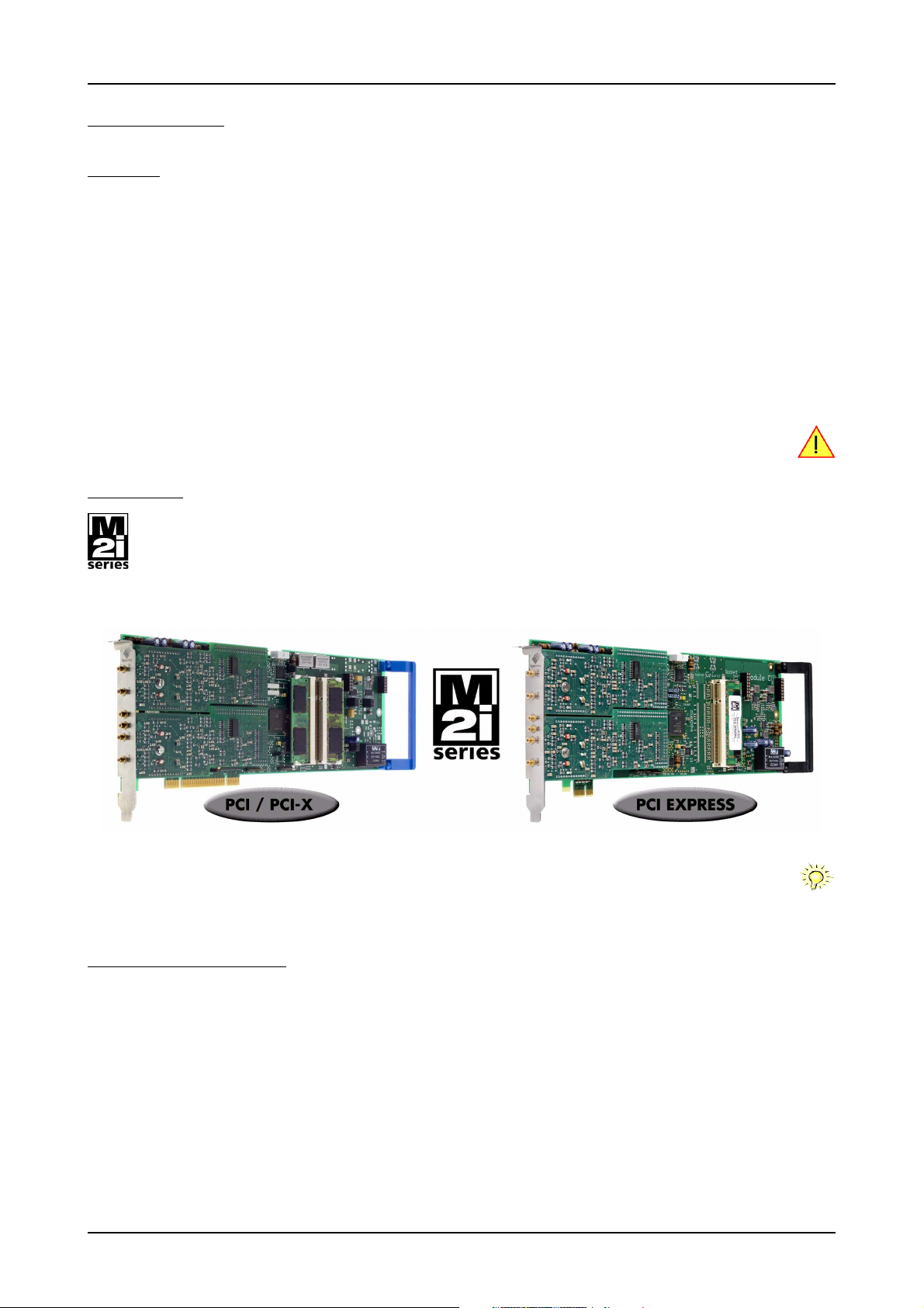
The PCI bus was first introduced in 1995. Nowadays it is the most common platform for PC based instrumentation boards. The very
wide range of installations world-wide, especially in the consumer market, makes it a platform of good value. Its successor is the
2004 introduced PCI Express standard. In today’s standard PC there are usually two to three slots of both standards available for
instrumentation boards. Special industrial PCs offer up to a maximum of 20 slots. The common PCI/PCI-X bus with data rates of up
to 133 MHz x 64 bit = 1 GByte/s per bus, is more and more replaced by the PCI Express standard with up to 4 GByte/s data transfer rate
per slot. The Spectrum M2i boards are available in two versions, for PCI/PCI-X as well as for PCI Express. The 100% software compatible
standards allow to combine both standards in one system with the same driver and software commands.
Within this document the name M2i is used as a synonym for both versions, either PCI/PCI-X or PCI Express. Only passages that
differ concerning the bus version of the M2i.xxxx and M2i.xxxx-exp cards are mentioned separately. Also all card drawings will
show the PCI/PCI-X version as example if no differences exist compared to the PCI Express version.
General Information
The M2i.30xx series offer a wide range of very fast 12 bit A/D converter boards for PCI-X, PCI and PCI Express (PCIe) bus. Due to the wellplanned design these boards are available in several versions and different speed grades. That makes it possible for the user to find an
individual solution.
These boards offer one to four channels with a maximum sample rate of 200 MS/s. As an option 4 digital inputs per channel can be recorded
synchronously. The installed memory of up to 2 GSample will be used for fast data recording. It can completely be used by the currently
active channels. If using slower sample rates the memory is switched to a FIFO buffer and data will be transferred online to the PC memory
or to hard disk.
Several boards of the M2i.xxxx series may be connected together by the internal standard synchronisation bus in combination with one of
the star-hub options to work with the same time base.
Application examples: Laboratory equipment, Supersonic, LDA/PDA, Radar, Spectroscopy.
(c) Spectrum GmbH 9
Page 10
Different models of the M2i.30xx series Introduction
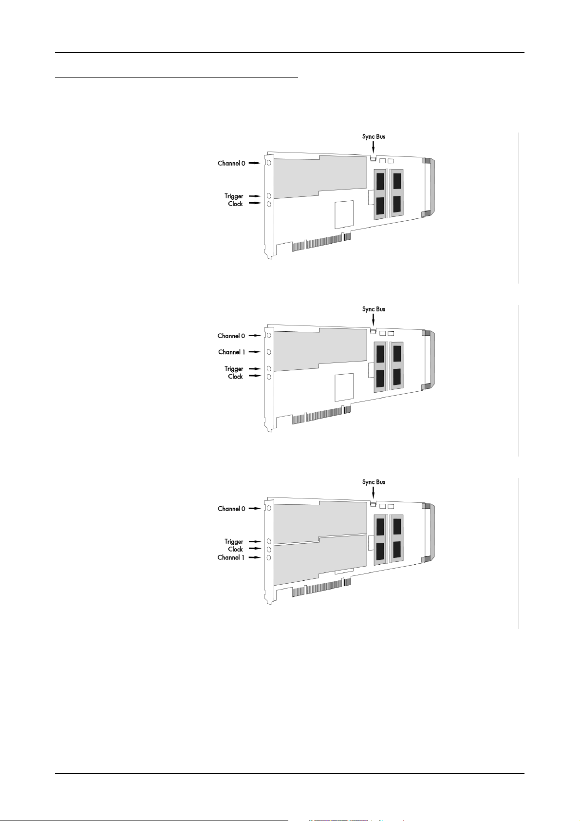
Different models of the M2i.30xx series
The following overview shows the different available models of the M2i.30xx series. They differ in the number mounted acquisition modules
and the number of available channels. You can also see the model dependent allocation of the output connectors.
• M2i.3010
• M2i.3020
• M2i.3010-exp
• M2i.3020-exp
• M2i.3011
• M2i.3012
• M2i.3021
• M2i.3022
• M2i.3031
• M2i.3011-exp
• M2i.3012-exp
• M2i.3021-exp
• M2i.3022-exp
• M2i.3031-exp
• M2i.3015
• M2i.3025
• M2i.3027
• M2i.3015-exp
• M2i.3025-exp
• M2i.3027-exp
10 M2i.30xx / M2i.30xx-exp Manual
Page 11

Introduction Different models of the M2i.30xx series
• M2i.3013
• M2i.3014
• M2i.3016
• M2i.3023
• M2i.3024
• M2i.3026
• M2i.3033
• M2i.3013-exp
• M2i.3014-exp
• M2i.3016-exp
• M2i.3023-exp
• M2i.3024-exp
• M2i.3026-exp
• M2i.3033-exp
(c) Spectrum GmbH 11
Page 12
Additional options Introduction
Additional options
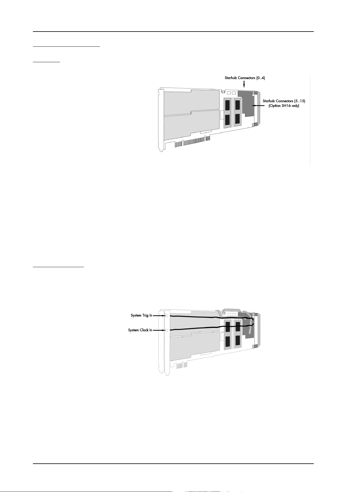
Star-Hub
The star hub piggy-back module allows the synchronisation of up to 16
M2i cards. It is possible to synchronize cards of the same type with
each other as well as different types.
Two different versions of the star-hub
module are available. A minor one
for synchronizing up to five boards
of the M2i series, without the need
for an additional system slot. The
major version (option SH16) allows
the synchronization of up to 16
cards with the need for an additional slot.
The module acts as a star hub for
clock and trigger signals. Each
board is connected with a small cable of the same length, even the master board. That minimizes the clock skew between the different cards. The figure shows the piggy-back
module mounted on the base board schematically without any cables to achieve a better visibility. It also shows the locations of the available
connectors for the two different versions of the star-hub option.
Any of the connected cards can be the clock master and the same or any other card can be the trigger master. All trigger modes that are
available on the master card are also available if the synchronization star-hub is used.
The cable connection of the boards is automatically recognized and checked by the driver when initializing the star-hub module. So no care
must be taken on how to cable the cards. The star-hub module itself is handled as an additional device just like any other card and the programming consists of only a few additional commands.
System Star-Hub
The System Star-Hub (SSH) option allows to synchronize clock and trigger information between Star-Hubs
located in multiple PC systems.
Therefore one system is set up as the
System-Master, generating the trigger and clock signals, which then
are distributed to all System-Slave
systems, and additionally also to the
System-Master itself, to minimize
phase delays.
All connected Star-Hubs therefore
have one additional PCI bracket installed, that allows to feed in clock
and trigger signals coming from the
System-Master distribution card (not
shown in the drawing). This bracket
comes pre-connected with your
M2i.xxxx or M2i-xxxx-exp card.M2i
For the System-Master there is additionally a clock and trigger distribution card included providing MMCX connectors on its bracket, to connect to up to 17 different systems (including the System-Master itself).
The installation and cabling from and to this System-Master distribution card will be shown in the according synchronization chapter later in
this manual.
12 M2i.30xx / M2i.30xx-exp Manual
Page 13

Introduction Additional options
BaseXIO (versatile digital I/O)
The option BaseXIO is simple-to-use
enhancement to the cards of the M2i
series. It is possible to control a wide
range of external instruments or
other equipment by using the eight
lines as asynchronous digital I/O.
The BaseXIO option is useful if an
external amplifier should be controlled, any kind of signal source must
be programmed, if status information from an external machine has to
be obtained or different test signals
have to be routed to the board.
In addition to the I/O features, these
lines are also for special functions.
Two of the lines can be used as additional TTL trigger inputs for complex gated conditions, one line can
be used as an reference time signal
(RefClock) for the timestamp option.
The BaseXIO MMCX connectors are mounted on-board. To gain easier access, these lines are connected to an extra bracket, that holds eight
SMB male connectors. For special purposes this option can also be ordered without the extra bracket and instead with internal cables.
The shown option is mounted exemplarily on a board with two modules and with the extra bracket. Of course you can also combine this
option as well with a board that is equipped with only one module.
Digital inputs
This option allows the user to acquire additional digital channels
synchronous and phase-stable
along with the analog data.
Therefore the analog data is filled
up with the digital bits up to 16 Bit
data width. This leads to a possibility of acquiring 4 additional digital
bits per channel with 12 bit resolution boards, and 2 additional digital
bits per channel with 14 bit resolution boards.
The connectors for these digital outputs are mounted on an additional
bracket. The figures show the option
on boards with either one or two
modules.
(c) Spectrum GmbH 13
Page 14
The Spectrum type plate Introduction
The Spectrum type plate
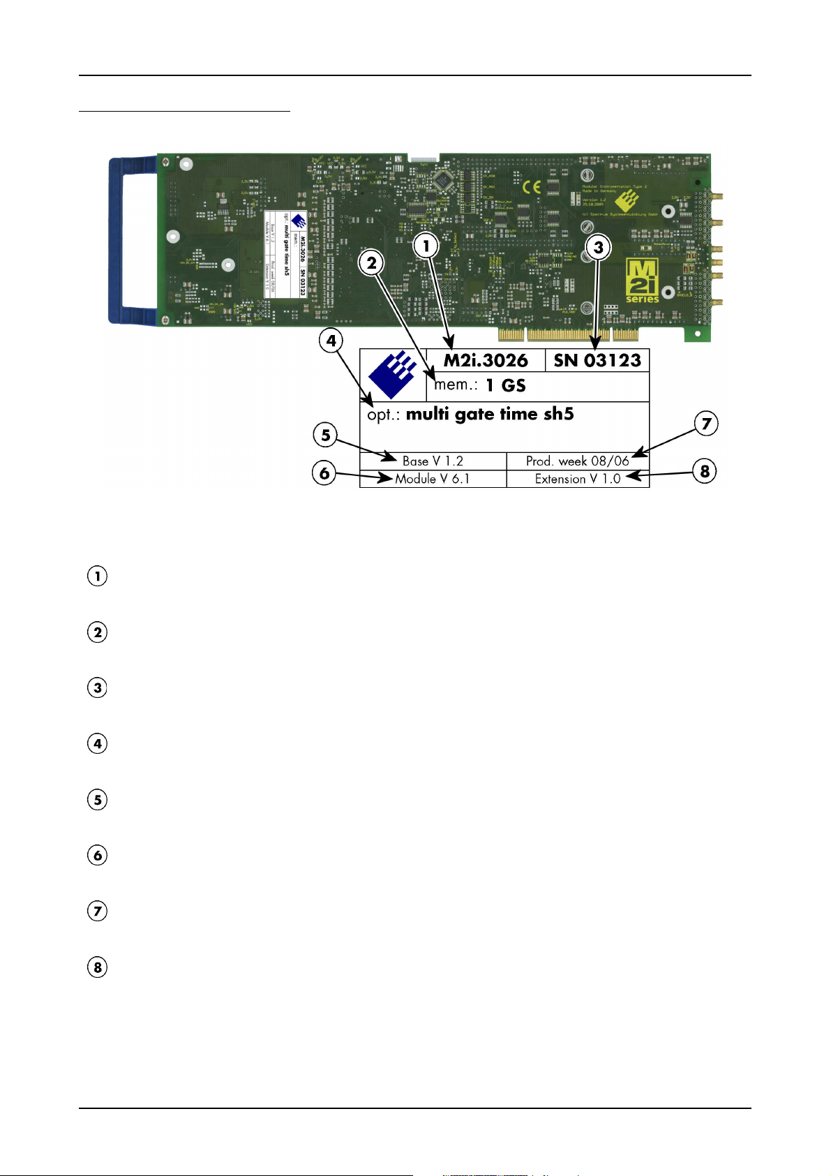
The Spectrum type plate, which consists of the following components, can be found on all of our boards. Please check whether the printed
information is the same as the information on your delivery note. All this information can also be read out by software:
The board type, consisting of the two letters describing the bus (in this case M2i for the PCI-X bus) and the model number.
The size of the on-board installed memory in MSample or GSample. In this example there are 1 GS = 1024 MSample (2 GByte =
2048 MByte) installed.
The serial number of your Spectrum board. Every board has a unique serial number.
A list of the installed options. A complete list of all available options is shown in the order information. In this example the options
Multiple recording, Gated Sampling, Timestamp and Star-Hub 5 are installed.
The base card version, consisting of the hardware version (the part before the dot) and the firmware version (the part after the dot).
The version of the analog/digital front-end module. Consisting of the hardware version (the part before the dot) and the firmware
version (the part after the dot)
The date of production, consisting of the calendar week and the year.
The version of the extension module if one is installed. Consisting of the hardware version (the part before the dot) and the firmware
version (the part after the dot). In our example we have the Star-Hub 5 extension module installed. Therefore the version of the ex-
tension module is filled on the type plate. If no extension module is installed this part is left open.
Please always supply us with the above information, especially the serial number in case of support request. That
allows us to answer your questions as soon as possible. Thank you.
14 M2i.30xx / M2i.30xx-exp Manual
Page 15
Introduction Hardware information
Hardware information
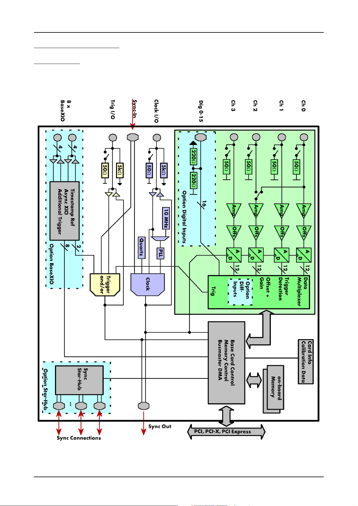
Block diagram
(c) Spectrum GmbH 15
Page 16

Hardware information Introduction
Technical Data
Analog Inputs
Resolution 12 bit
Input Range software programmable ±200 mV, ±500 mV, ±1 V, ±2 V, ±5 V, ±10 V
Input Mode fixed bipolar, single-ended
Input Offset software programmable ±100% of input range in steps of 1%
ADC Differential non linearity (DNL) ADC only ±1 LSB
ADC Integral non linearity (INL) ADC only ±1 LSB
Offset error (full speed) after warm-up and calibration ≤ 0.1% of range
Gain error (full speed) after warm-up and calibration ≤ 1% of current value
Crosstalk: 1 MHz Signal, 50 Ω termination all input ranges ≤ -70 dB on adjacent channels
Analog Input impedance software programmable 50 Ω or 1 MΩ || 25 pF
Analog input coupling fixed DC
Over voltage protection (active card) ranges ≤ ±1 V ±5 V
Over voltage protection (active card) ranges > ±1 V ±50 V
Input signal with 50 Ω termination max 5 V rms
Channel selection software programmable 1, 2 or 4 (maximum is model dependent)
Trigger
Available trigger modes software programmable Channel Trigger, External, Software, Window, Pulse, Re-Arm, Or/And, Delay
Trigger level resolution software programmable 10 bit
Trigger edge software programmable Rising edge, falling edge or both edges
Trigger pulse width software programmable 0 to [64k - 1] samples in steps of 1 sample
Trigger delay software programmable 0 to [64k - 1] samples in steps of 1 sample
Multi, Gate: re-arming time < 4 samples (+ programmed pretrigger)
Pretrigger at Multi, ABA, Gate, FIFO software programmable 4 up to [8176 Samples / number of active channels] in steps of 4
Posttrigger software programmable 4 up to [8G - 4] samples in steps of 4 (defining pretrigger in standard scope mode)
Memory depth software programmable 8 up to [installed memory / number of active channels] samples in steps of 4
Multiple Recording/ABA segment size software programmable 8 up to [installed memory / 2 / active channels] samples in steps of 4
Trigger output delay One positive edge after internal trigger event
Internal trigger accuracy 1 sample
External trigger accuracy ≤ 100 MS/s 1 sample
External trigger accuracy > 100 MS/s 2 samples
External trigger type (input and output) 3.3V LVTTL compatible (5V tolerant with base card hardware version > V20)
External trigger input Low ≤ 0.8 V, High ≥ 2.0 V, ≥ 8 ns in pulse stretch mode, ≥ 2 clock periods all other modes
External trigger maximum voltage -0.5 V up to +5.7 V (internally clamped to 5.0V, 100 mA max. clamping current)
Trigger impedance software programmable 50 Ohm / high impedance (> 4kOhm)
External trigger output type 3.3 V LVTTL
External trigger output levels Low ≤ 0.4 V, High ≥ 2.4 V, TTL compatible
External trigger output drive strength Capable of driving 50 ohm load, maximum drive strength ±128 mA
Clock
Clock Modes software programmable internal PLL, internal quartz, external clock, external divided, external reference clock, sync
Internal clock range (PLL mode) software programmable 1 kS/s to max using internal reference, 50kS/s to max using external reference clock
Internal clock accuracy ≤ 20 ppm
Internal clock setup granularity ≤1% of range (100M, 10M, 1M, 100k,...): Examples: range 1M to 10M: stepsize ≤ 100k
External reference clock range software programmable ≥ 1.0 MHz and ≤ 125.0 MHz
External clock impedance software programmable 50 Ohm / high impedance (> 4kOhm)
External clock range see „Dynamic Parameters“ table below
External clock delay to internal clock 5.4 ns
External clock type/edge 3.3V LVTTL compatible, rising edge used
External clock input Low level ≤ 0.8 V, High level ≥ 2.0 V, duty cycle: 45% - 55%
External clock maximum voltage -0.5 V up to +3.8 V (internally clamped to 3.3V, 100 mA max. clamping current)
External clock output type 3.3 V LVTTL
External clock output levels Low ≤ 0.4 V, High ≥ 2.4 V, TTL compatible
External clock output drive strength Capable of driving 50 ohm load, maximum drive strength ±128 mA
Synchronization clock divider software programmable 2 up to [8k - 2] in steps of 2
ABA mode clock divider for slow clock software programmable 8 up to 524280 in steps of 8
(not 5V tolerant)
BaseXIO Option
BaseXIO modes software programmable Asynch digital I/O, 2 additional trigger, timestamp reference clock, timestamp digital inputs
BaseXIO direction software programmable Each 4 lines can be programmed in direction
BaseXIO input TTL compatible: Low ≤ 0.8 V, High ≥ 2.0 V
BaseXIO input impedance 4.7 kOhm towards 3.3 V
BaseXIO input maximum voltage -0.5 V up to +5.5 V
BaseXIO output type 3.3 V LVTLL
BaseXIO output levels TTL compatible: Low ≤ 0.4 V, High ≥ 2.4 V
BaseXIO output drive strength
16 M2i.30xx / M2i.30xx-exp Manual
32 mA maximum current, no 50 Ω loads
Page 17

Introduction Hardware information
Digital Inputs Option
Digital data acquisition modes software programmable 4 digital inputs per active analog channel
Digital inputs delay to analog sample -11 Samples
Input Impedance 110 Ω at 2.5 V
Maximum voltage -0.3 V up to +5.5 V (internally clamped to 3.3V and ground, 200 mA max. clamping current)
Input voltage Low ≤ 0.8 V, High > 2.0 V (TTL compatible)
Connectors
Analog Inputs 3 mm SMB male (one for each single-ended input) Cable-Type: Cab-3f-xx-xx
Trigger Input/Output programmable direction 3 mm SMB male (one connector) Cable-Type: Cab-3f-xx-xx
Clock Input/Output programmable direction 3 mm SMB male (one connector) Cable-Type: Cab-3f-xx-xx
Option Digital Inputs/Outputs 40 pole half pitch (Hirose FX2 series) Cable-Type: Cab-d40-xx-xx
Option BaseXIO 8 x 3 mm SMB male on extra bracket, internally 8 x MMCX female
Environmental and Physical Details
Dimension (PCB only) 312 mm x 107 mm (full PCI length)
Width (Standard or with option star-hub 5) 1 full size slot
Width (star-hub 16) additionally back of adjacent neighbour slots
Width (with option BaseXIO) additionally extra bracket on neighbour slot
Width (with option -digin, -digout or -60xx-AmpMod) additionally half length of adjacent neighbour slot
Weight (depending on version) 290g (smallest version) up to 460g (biggest version with all options, including star-hub)
Warm up time 10 minutes
Operating temperature 0°C to 50°C
Storage temperature -10°C to 70°C
Humidity 10% to 90%
PCI/PCI-X specific details
PCI / PCI-X bus slot type 32 bit 33 MHz or 32 bit 66 MHz
PCI / PCI-X bus slot compatibility 32/64 bit, 33-133 MHz, 3,3 V and 5 V I/O
Sustained streaming mode > 245 MB/s (in a PCI-X slot clocked at 66 MHz or higher)
PCI Express specific details
PCIe slot type x1 Generation 1
PCIe slot compatibility x1/x4/x8/x16 (Some x16 PCIe slots are for graphic cards only and can not be used)
Sustained streaming mode > 160 MB/s
Certification, Compliance, Warranty
EMC Immunity Compliant with CE Mark
EMC Emission Compliant with CE Mark
Product warranty 5 years starting with the day of delivery
Software and firmware updates Life-time, free of charge
Power Consumption
PCI / PCI-X PCI EXPRESS
3.3 V 5 V Total 3.3V 12V Total
M2i.30x0 (256 MSample memory) 2.2 A 0.8 A 11.3 W 0.4 A 1.0 A 13.3 W
M2i.30x1, 30x2 (256 MSample memory) 2.3 A 0.9 A 12.1 W 0.4 A 1.1 A 14.5 W
M2i.30x5, 30x7 (256 MSample memory) 2.5 A 1.1 A 13.8 W 0.4 A 1.2 A 15.7 W
M2i.30x3, 30x4, 30x6 (256 MSample memory) 2.6 A 1.4 A 15.6 W 0.4 A 1.4 A 18.1 W
M2i.3026 (2 GSample memory) max power 3.7 A 1.4 A 19.2 W 0.4 A 2.0 A 25.3 W
MTBF
MTBF 500000 hours
(c) Spectrum GmbH 17
Page 18

Hardware information Introduction
Dynamic Parameters
M2i.3011
M2i.3013
min internal clock 1 kS/s 1kS/s 1kS/s 1kS/s 1kS/s 1kS/s 1kS/s
max internal clock 40 MS/s 50 MS/s 62.5 MS/s 80 MS/s 105 MS/s 160 MS/s 200 MS/s
min external clock 1 MS/s 1 MS/s 1 MS/s 1 MS/s 1 MS/s 1 MS/s 1 MS/s
max external clock 40 MS/s 50 MS/s 62.5 MS/s 80 MS/s 105 MS/s 80 MS/s 105 MS/s
-3 dB bandwidth DC to 20 MHz DC to 25 MHz DC to 30 MHz DC to 40 MHz DC to 40 MHz DC to 40 MHz DC to 40 MHz
Zero noise level (< 125 MS/s) < 1.1 LSB rms < 1.1 LSB rms < 1.4 LSB rms < 1.5 LSB rms < 1.5 LSB rms < 2.0 LSB rms < 2.0 LSB rms
Zero noise level (> 125 MS/s) n.a. n.a. n.a. n.a. n.a. < 3.0 LSB rms < 3.0 LSB rms
Test - sampling rate 40 MS/s 50 MS/s 60 MS/s 80 MS/s 100 MS/s 80 MS/s 100 MS/s
Test signal frequency 1 MHz4 MHz1 MHz4 MHz1 MHz4 MHz1 MHz9 MHz1 MHz9 MHz1 MHz9 MHz1 MHz9 MHz
SNR (typ) (dB) 66.2 64.8 65.2 64.5 64.5 63.5 65.2 63.3 65.1 63.0 65.0 62.8 65.0 62.5
THD (typ) (dB) -74.0 -71.0 -72.3 -71.0 -70.5 -68.9 -72.2 -66.5 -72.0 -66.1 -69.8 -65.9 -69.5 -65.8
SFDR (typ), excl. harm. (dB) 80.4 77.9 80.2 77.8 80.0 78.0 79.0 77.9 78.0 77.5 78.2 77.0 77.8 76.9
ENOB based on SNR (bit) 10.7 10.5 10.6 10.4 10.5 10.3 10.6 10.2 10.6 10.2 10.5 10.1 10.4 10.1
ENOB based on SINAD (bit) 10.6 10.3 10.5 10.2 10.3 10.1 10.4 10.1 10.4 10.1 10.4 10.0 10.3 9.9
Dynamic parameters are measured at ± 1 V input range (if no other range is stated) and 50 Ohm termination with the samplerate specified in the table. Measured parameters are averaged 20 times to get typical values. Test signal is a pure sine wave of the specified frequency with > 99% amplitude. SNR and RMS noise parameters may differ depending on the quality
of the used PC. SNR = Signal to Noise Ratio, THD = Total Harmonic Distortion, SFDR = Spurious Free Dynamic Range, SINAD = Signal Noise and Distortion, ENOB = Effective Number
of Bits. For a detailed description please see application note 002.
M2i.3021
M2i.3023
M2i.3031
M2i.3033
M2i.3010
M2i.3012
M2i.3014
M2i.3020
M2i.3022
M2i.3024
M2i.3027
M2i.3015
M2i.3016
M2i.3025
M2i.3026
18 M2i.30xx / M2i.30xx-exp Manual
Page 19
Introduction Hardware information
Order InformationThe card is delivered with 256 MSample on-board memory and supports standard acquisition (Scope), FIFO ac-
quisition (streaming), Multiple Recording, Gated Sampling, ABA mode and Timestamps. Operating system drivers for Windows/Linux 32 bit
and 64 bit, examples for C/C++, LabVIEW (Windows), MATLAB (Windows and Linux), LabWindows/CVI, IVI, .NET, Delphi, Visual Basic,
Java, Python and a Base license of the oscilloscope software SBench 6 are included. Drivers for other 3rd party products like VEE or DASYLab
may be available on request.
Adapter cables are not included. Please order separately!
PCI Express (PCIe)
PCI/PCI-X
Memory
Options
Services
Cables
Amplifiers
Software SBench6
Software Options
(1)
: Just one of the options can be installed on a card at a time.
(2)
: Third party product with warranty differing from our export conditions. No volume rebate possible.
PCI Express PCI/PCI-X Standard mem 1 channel 2 channels 4 channels
M2i.3010-exp M2i.3010 256 MSample 80 MS/s
M2i.3011-exp M2i.3011 256 MSample 40 MS/s 40 MS/s
M2i.3012-exp M2i.3012 256 MSample 80 MS/s 40 MS/s
M2i.3013-exp M2i.3013 256 MSample 40 MS/s 40 MS/s 40 MS/s
M2i.3014-exp M2i.3014 256 MSample 80 MS/s 80 MS/s 40 MS/s
M2i.3015-exp M2i.3015 256 MSample 160 MS/s 80 MS/s
M2i.3016-exp M2i.3016 256 MSample 160 MS/s 80 MS/s 40 MS/s
M2i.3020-exp M2i.3020 256 MSample 100 MS/s
M2i.3021-exp M2i.3021 256 MSample 50 MS/s 50 MS/s
M2i.3022-exp M2i.3022 256 MSample 100 MS/s 50 MS/s
M2i.3023-exp M2i.3023 256 MSample 50 MS/s 50 MS/s 50 MS/s
M2i.3024-exp M2i.3024 256 MSample 100 MS/s 100 MS/s 50 MS/s
M2i.3025-exp M2i.3025 256 MSample 200 MS/s 100 MS/s
M2i.3026-exp M2i.3026 256 MSample 200 MS/s 100 MS/s 50 MS/s
M2i.3027-exp M2i.3027 256 MSample 100 MS/s 100 MS/s
M2i.3031-exp M2i.3031 256 MSample 60 MS/s 60 MS/s
M2i.3033-exp M2i.3033 256 MSample 60 MS/s 60 MS/s 60 MS/s
Order no. Option
M2i.xxxx-512MS Memory upgrade to 512 MSample (1 GB) total memory
M2i.xxxx-1GS Memory upgrade to 1 GSample (2 GB) total memory
Order no. Option
M2i.xxxx-diff Digital differential mode for combining two single-ended channels to one differential channel.
M2i.xxxx-SH5 (1) Synchronization Star-Hub for up to 5 cards, only 1 slot width
M2i.xxxx-SH16 (1) Synchronization Star-Hub for up to 16 cards
M2i.xxxx-SSHM (1) System-Star-Hub Master for up to 15 cards in the system and up to 17 systems, PCI 32 Bit card,
M2i.xxxx-SSHMe (1) System-Star-Hub Master for up to 15 cards in the system and up to 17 systems, PCI Express card,
sync cables and extra bracket for clock and trigger distribution included
sync cables and extra bracket for clock and trigger distribution included
M2i.xxxx-SSHS5 (1) System-Star-Hub Slave for 5 cards in one system, one slot width all sync cables + bracket included
M2i.xxxx-SSHS16 (1) System-Star-Hub Slave for 16 cards in system, two slots width, all sync cables + bracket included
M2i.3xxx-dig Additional synchronous digital inputs (4 per analog channel) including Cab-d40-idc-100
M2i.xxxx-bxio Option BaseXIO: 8 digital I/O lines usable as asynchronous I/O, timestamp ref-clock and additional
external trigger lines, additional bracket with 8 SMB connectors
M2i-upgrade Upgrade for M2i.xxxx: later installation of option -M2i.xxxx-1GS, -SH5, -SH16 or -bxio
Order no.
Recal Recalibration at Spectrum incl. calibration protocol
Order no.
for Connections Length to BNC male to BNC female to SMA male to SMA female to SMB female
Analog/Clock/Trigger 80 cm Cab-3f-9m-80 Cab-3f-9f-80 Cab-3f-3mA-80 Cab-3f-3fA-80 Cab-3f-3f-80
Analog/Clock/Trigger 200 cm Cab-3f-9m-200 Cab-3f-9f-200 Cab-3f-3mA-200 Cab-3f-3fA-200 Cab-3f-3f-200
Probes (short) 5 cm Cab-3f-9f-5
to 2x20 pole IDC to 40 pole FX2
Digital signals (option) 100 cm Cab-d40-idc-100 Cab-d40-d40-100
Order no. Bandwidth Connection Input Impedance Coupling Amplification
(2)
SPA.1412
(2)
SPA.1411
(2)
SPA.1232
(2)
SPA.1231
Information External Amplifiers with one channel, BNC/SMA female connections on input and output, manually adjustable offset, man-
200 MHz BNC 1 MOhm AC/DC x10/x100 (20/40 dB)
200 MHz BNC 50 Ohm AC/DC x10/x100 (20/40 dB)
10 MHz BNC 1 MOhm AC/DC x100/x1000 (40/60 dB)
10 MHz BNC 50 Ohm AC/DC x100/x1000 (40/60 dB)
ually switchable settings. An external power supply for 100 to 240 VAC is included. Please be sure to order an adapter
cable matching the amplifier connector type and matching the connector type for your A/D card input.
Order no.
SBench6 Base version included in delivery. Supports standard mode for one card.
SBench6-Pro Professional version for one card: FIFO mode, export/import, calculation functions
SBench6-Multi Option multiple cards: Needs SBench6-Pro. Handles multiple synchronized cards in one system.
Volume Licenses Please ask Spectrum for details.
Order no.
SPc-RServer Remote Server Software Package - LAN remote access for M2i/M3i/M4i/M4x/M2p cards
SPc-SCAPP Spectrum’s CUDA Access for Parallel Processing - SDK for direct data transfer between Spectrum card
and CUDA GPU. Includes RDMA activation and examples. Signed NDA needed for access.
(c) Spectrum GmbH 19
Page 20

System Requirements Hardware Installation
Hardware Installation
System Requirements
All Spectrum M2i/M3i.xxxx instrumentation cards are compliant to the PCI standard and require in general one free full length slot. This can
either be a standard 32 bit PCI legacy slot, a 32 bit or a 64 bit PCI-X slot. Depending on the installed options additional free slots can be
necessary.
All Spectrum M2i/M3i.xxxx-exp instrumentation cards are compliant to the PCI Express 1.0 standard and require in general one free full
length PCI Express slot. This can either be a x1, x4, x8 or x16 slot. Some x16 PCIe slots are for the use of graphic cards only and can not
be used for other cards. Depending on the installed options additional free slots can be necessary.
Warnings
ESD Precautions
The boards of the M2i/M3i.xxxx series contain electronic components that can be damaged by electrostatic discharge (ESD).
Before installing the board in your system or even before touching it, it is absolutely necessary to bleed off
any electrostatic electricity.
Cooling Precautions
The boards of the M2i/M3i.xxxx series operate with components having very high power consumption at high speeds. For this reason it is
absolutely required to cool this board sufficiently.
For all M2i/M3i cards it is strongly recommended to install an additional cooling fan producing a stream of air across the boards
surface. In most cases professional PC-systems are already equipped with sufficient cooling power. In that case please make sure
that the air stream is not blocked.
Sources of noise
The analog acquisition and generator boards of the M2i/M3i.xxxx series should be placed far away from any noise producing source (like
e.g. the power supply). It should especially be avoided to place the board in the slot directly adjacent to another fast board (like the graphics
controller).
20 M2i.30xx / M2i.30xx-exp Manual
Page 21
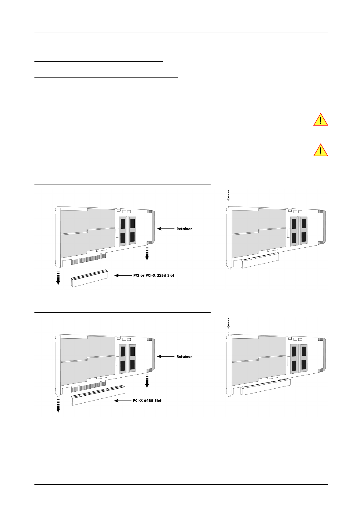
Hardware Installation Installing the board in the system
Installing the board in the system
Installing a single board without any options
Before installing the board you first need to unscrew and remove the dedicated blind-bracket usually mounted to cover unused slots of your
PC. Please keep the screw in reach to fasten your Spectrum card afterwards. All Spectrum cards require a full length PCI, PCI-X slot (either
32Bit or 64Bit) or PCI Express slot (either x1, x4, x8 or x16) with a track at the backside to guide the board by its retainer. Now insert the
board slowly into your computer. This is done best with one hand each at both fronts of the board.
While inserting the board take care not to tilt the retainer in the track. Please take especial care to not bend
the card in any direction while inserting it in the system. A bending of the card may damage the PCB totally
and is not covered by the standard warranty.
Please be very carefully when inserting the board in the slot, as most of the mainboards are mounted with
spacers and therefore might be damaged if they are exposed to high pressure.
After the board’s insertion fasten the screw of the bracket carefully, without overdoing.
Installing the M2i/M3i.xxxx PCI/PCI-X card in a 32 bit PCI/PCI-X slot
Installing the M2i/M3i.xxxx PCI/PCI-X card in a 64 bit PCI/PCI-X slot
(c) Spectrum GmbH 21
Page 22
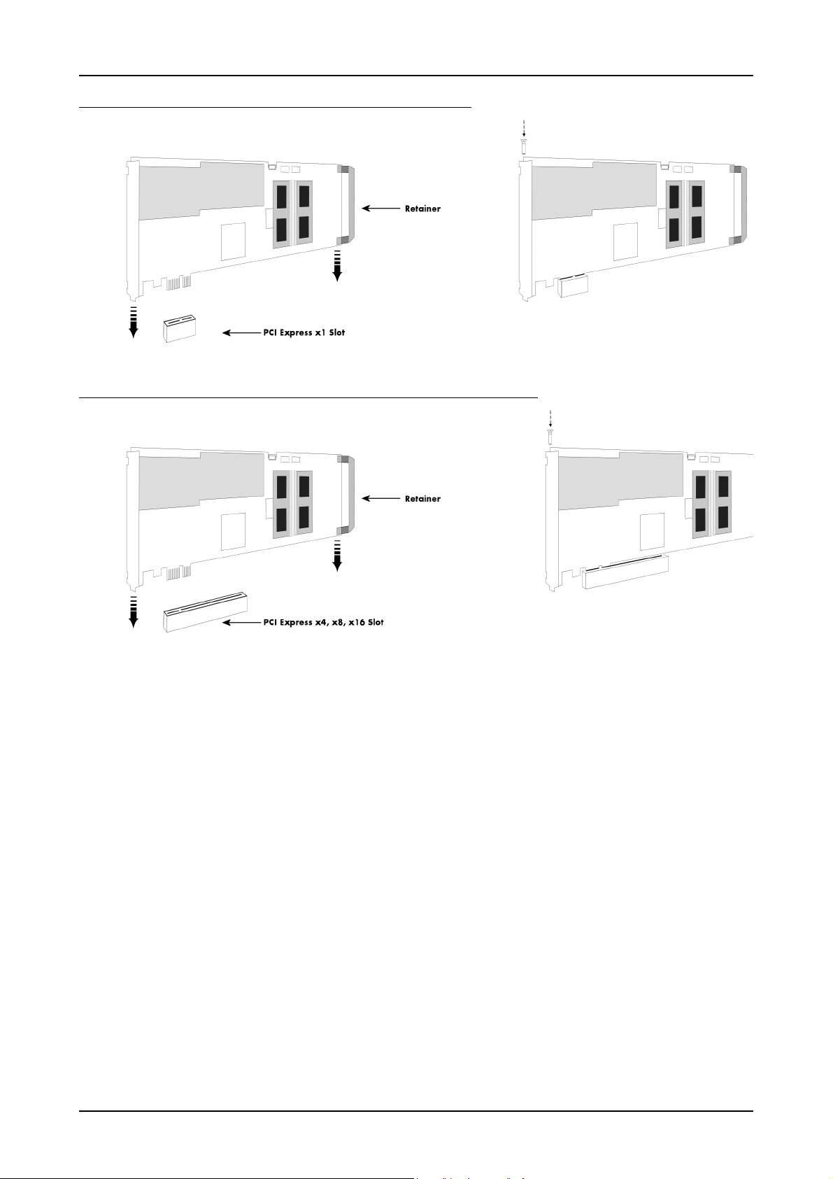
Installing the board in the system Hardware Installation
Installing the M2i/M3i.xxxx-exp PCI Express card in a PCIe x1 slot
Installing the M2i/M3i.xxxx-exp PCI Express card in a PCIe x4, x8 or x16 slot
22 M2i.30xx / M2i.30xx-exp Manual
Page 23
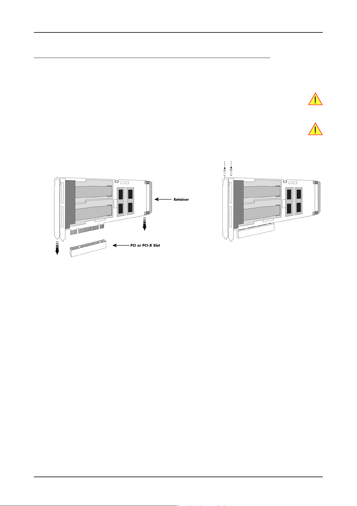
Hardware Installation Installing the board in the system
Installing a board with digital inputs/outputs mounted on an extra bracket
Before installing the board you first need to unscrew and remove the dedicated blind-brackets usually mounted to cover unused slots of your
PC. Please keep the screws in reach to fasten your Spectrum board and the extra bracket afterwards. All Spectrum boards require a full length
PCI slot with a track at the backside to guide the board by its retainer. Now insert the board and the extra bracket slowly into your computer.
This is done best with one hand each at both fronts of the board.
While inserting the board take care not to tilt the retainer in the track. Please take especial care to not bend
the card in any direction while inserting it in the system. A bending of the card may damage the PCB totally
and is not covered by the standard warranty.
Please be very carefully when inserting the board in the PCI slot, as most of the mainboards are mounted
with spacers and therefore might be damaged they are exposed to high pressure.
After the board’s insertion fasten the screws of both brackets carefully, without overdoing. The figure shows an example of a board with two installed modules.
(c) Spectrum GmbH 23
Page 24
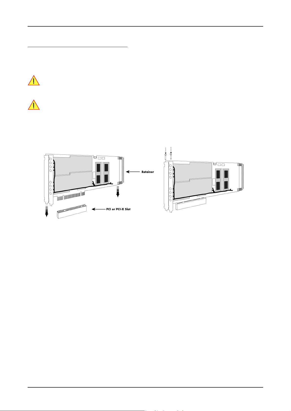
Installing the board in the system Hardware Installation
Installing a board with option BaseXIO
Before installing the board you first need to unscrew and remove the dedicated blind-brackets usually mounted to cover unused slots of your
PC. Please keep the screws in reach to fasten your Spectrum board and the extra bracket afterwards. All Spectrum boards require a full length
PCI slot with a track at the backside to guide the board by its retainer. Now insert the board and the extra bracket slowly into your computer.
This is done best with one hand each at both fronts of the board.
While inserting the board take care not to tilt the retainer in the track. Please take especial care to not bend
the card in any direction while inserting it in the system. A bending of the card may damage the PCB totally
and is not covered by the standard warranty.
Please be very carefully when inserting the board in the PCI slot, as most of the mainboards are mounted
with spacers and therefore might be damaged they are exposed to high pressure.
After the board’s insertion fasten the screws of both brackets carefully, without overdoing. The figure shows an example of a board with two installed modules.
24 M2i.30xx / M2i.30xx-exp Manual
Page 25
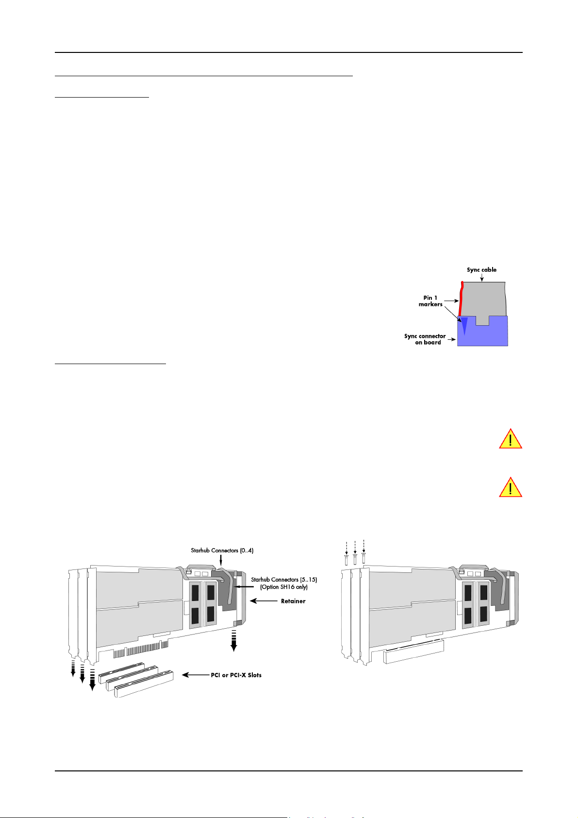
Hardware Installation Installing the board in the system
Installing multiple boards synchronized by star-hub option
Hooking up the boards
Before mounting several synchronized boards for a multi channel system into the PC you can hook up the cards with their synchronization
cables first. If there is enough space in your computer’s case (e.g. a big tower case) you can also mount the boards first and hook them up
afterwards. Spectrum ships the card carrying the star-hub option together with the needed amount of synchronization cables. All of them are
matched to the same length, to achieve a zero clock delay between the cards.
Only use the included flat ribbon cables.
All of the cards, including the one that carries the star-hub piggy-back module, must be wired to the star-hub as the figure is showing as an
example for three synchronized boards.
It does not matter which of the available connectors on the star-hub module you use for which board. The software driver will detect the types
and order of the synchronized boards automatically. The figure shows the three cables mounted on the option M2i.xxxx-SH16 star-hub to
achieve a better visibility. The option M3i.xxxx-SH8 is handled similar to this picture. When using the M3i.xxxx-SH4 or M2i.xxxx-SH5 version,
only the connectors on the upper side of the star-hub piggy-back module are available (see figure for details on the star-hub connector locations).
As some of the synchronization cables are not secured against wrong plugging you should take
care to have the pin 1 markers on the multiple connectors and the cable on the same side, as the
figure on the right is showing.
Mounting the wired boards
Before installing the cards you first need to unscrew and remove the dedicated blind-brackets usually mounted to cover unused slots of your
PC. Please keep the screws in reach to fasten your Spectrum cards afterwards. All Spectrum boards require a full length PCI slot with a track
at the backside to guide the card by its retainer. Now insert the cards slowly into your computer. This is done best with one hand each at
both fronts of the board. Please keep in mind that the board carrying the star-hub piggy-back module requires the width of two slots, when
the option M3i.xxxx-SH8 or M2i.xxxx-SH16 version is used.
While inserting the board take care not to tilt the retainer in the track. Please take especial care to not bend
the card in any direction while inserting it in the system. A bending of the card may damage the PCB totally
and is not covered by the standard warranty.
Please be very careful when inserting the cards in the slots, as most of the mainboards are mounted with
spacers and therefore might be damaged if they are exposed to high pressure.
After inserting all cards fasten the screws of all brackets carefully, without overdoing. The figure shows an example of three cards with two
installed modules each.
(c) Spectrum GmbH 25
Page 26
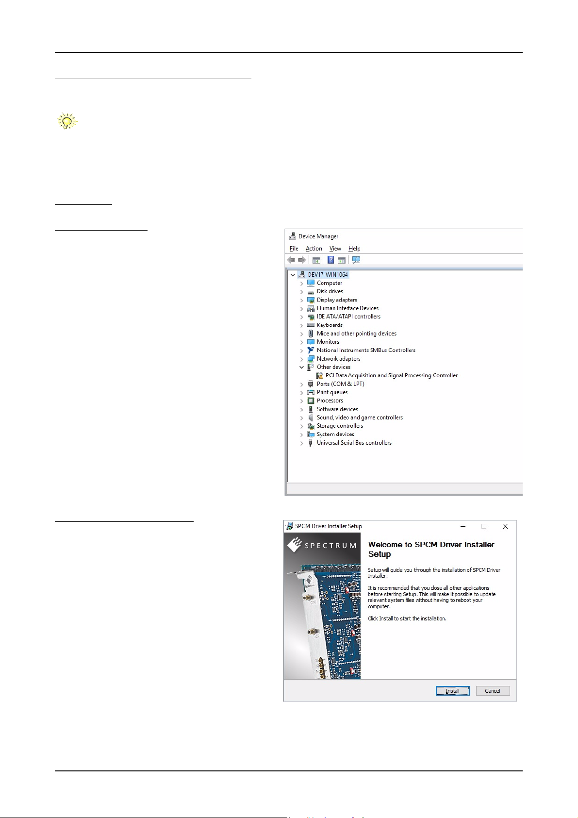
Windows Software Driver Installation
Software Driver Installation
Before using the board a driver must be installed that matches the operating system.
Since driver V3.33 (released on CD V3.48 in August 2017) the installation is done via an installer exectutable
rather than manually via ths Windows Device Manager. The steps for manually installing a card has since
been moved to a separate application note „AN008 - Legacy Windows Driver Installation“.
This new installer is common on all currently supported Windows platforms (Windows 7, Windows 8 and Windows 10) both 32bit and
64bit. The driver from the CD supports all cards of the M2i/M3i or M4i/M4x series. That means that you can use the same driver for all
cards of these families.
Windows
Before installation
When you install a card for the very first time, Windows will discover the new hardware and might try to search the Microsoft
Website for available matching driver modules.
Prior to running the Spectrum installer, the card will appear in the
Windows device manager as an generalized card (in case of
Windows 10 as a „PCIe Data Acquisition and Signal Processing
Controller“ as shown here.
Running the driver Installer
Simply run the installer supplied on the CD (..Driver\windows“
folder or downloadable from www.spectrum-instrumentation.com
26 M2i.30xx / M2i.30xx-exp Manual
Page 27
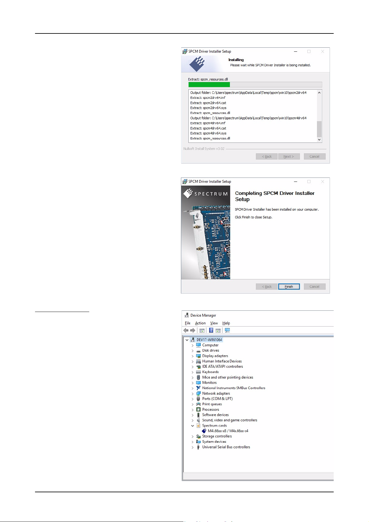
Software Driver Installation Windows
After installation
After running the Spectrum driver installer, the card will appear in
the Windows device manager with its name matching the card series.
The card is now ready to be used.
(c) Spectrum GmbH 27
Page 28

Linux Software Driver Installation
Linux
Overview
The Spectrum M2i/M3i/M4i/M4x/M2p cards and digitizerNETBOX/generatorNETBOX products are delivered with Linux drivers suitable
for Linux installations based on kernel 2.4, 2.6, 3.x or 4.x, single processor (non-SMP) and SMP systems, 32 bit and 64 bit systems. As each
Linux distribution contains different kernel versions and different system setup it is in nearly every case necessary, to have a directly matching
kernel driver for card level products to run it on a specific system. For digitizerNETBOX/generatorNETBOX products the library is suffcient
and no kernel driver has to be installed.
Spectrum delivers pre-compiled kernel driver modules for a number of common distributions with the cards. You may try to use one of these
kernel modules for different distributions which have a similar kernel version. Unfortunately this won’t work in most cases as most Linux system
refuse to load a driver which is not exactly matching. In this case it is possible to get the kernel driver sources from Spectrum. Please contact
your local sales representative to get more details on this procedure.
The Standard delivery contains the pre-compiled kernel driver modules for the most popular Linux distributions, like Suse, Debian, Fedora and Ubuntu. The list with all pre-compiled and readily supported distributions and their respective kernel version can be found under:
http://spectrum-instrumentation.com/en/supported-linux-distributions
The Linux drivers have been tested with all above mentioned distributions by Spectrum. Each of these distributions has been installed with the default setup using no kernel updates. A lot more different distributions
are used by customers with self compiled kernel driver modules.
or via the shown QR code.
Standard Driver Installation
The driver is delivered as installable kernel modules together with libraries to access the kernel driver. The installation script will help you with
the installation of the kernel module and the library.
This installation is only needed if you are operating real locally installed cards. For software emulated demo
cards, remotely installed cards or for digitizerNETBOX/generatorNETBOX products it is only necessary to install the libraries as explained further below.
Login as root
It is necessary to have the root rights for installing a driver.
Call the install.sh <install_path> script
This script will install the kernel module and some helper scripts to a given directory. If you do not specify a directory it will use your home
directory as destination. It is possible to move the installed driver files later to any other directory.
The script will give you a list of matching kernel modules. Therefore it checks for the system width (32 bit or 64 bit) and the processor (single
or smp). The script will only show matching kernel modules. Select the kernel module matching your system. The script will then do the following steps:
• copy the selected kernel module to the install directory (spcm.o or spcm.ko)
• copy the helper scripts to the install directory (spcm_start.sh and spc_end.sh)
• copy and rename the matching library to /usr/lib (/usr/lib/libspcm_linux.so)
Udev support
Once the driver is loaded it automatically generates the device nodes under /dev. The cards are automatically named to /dev/spcm0,
/dev/spcm1,...
You may use all the standard naming and rules that are available with udev.
Start the driver
Starting the driver can be done with the spcm_start.sh script that has been placed in the install directory. If udev is installed the script will only
load the driver. If no udev is installed the start script will load the driver and make the required device nodes /dev/spcm0... for accessing
the drivers. Please keep in mind that you need root rights to load the kernel module and to make the device nodes!
Using the dedicated start script makes sure that the device nodes are matching your system setup even if new hardware and drivers have
been added in between. Background: when loading the device driver it gets assigned a „major“ number that is used to access this driver.
All device nodes point to this major number instead of the driver name. The major numbers are assigned first come first served. This means
that installing new hardware may result in different major numbers on the next system start.
28 M2i.30xx / M2i.30xx-exp Manual
Page 29

Software Driver Installation Linux
Get first driver info
After the driver has been loaded successfully some information about the installed boards can be found in the /proc/spcm_cards file. Some
basic information from the on-board EEProm is listed for every card.
cat /proc/spcm_cards
Stop the driver
You may want to unload the driver and clean up all device nodes. This can be done using the spcm_end.sh script that has also been placed
in the install directory
Standard Driver Update
A driver update is done with the same commands as shown above. Please make sure that the driver has been stopped before updating it.
To stop the driver you may use the spcm_end.sh script.
Compilation of kernel driver sources (option)
The driver sources are only available for existing customers on special request and against a signed NDA. The driver sources are not part of
the standard delivery. The driver source package contains only the sources of the kernel module, not the sources of the library.
Please do the following steps for compilation and installation of the kernel driver module:
Login as root
It is necessary to have the root rights for installing a driver.
Call the compile script make_spcm_linux_kerneldrv.sh
This script will examine the type of system you use and compile the kernel with the correct settings. If using a kernel 2.4 the makefile expects
two symbolic links in your system:
• /usr/src/linux pointing to the correct kernel source directory
• /usr/src/linux/.config pointing to the currently used kernel configuration
The compile script will then automatically call the install script and install the just compiled kernel module in your home directory. The rest of
the installation procedure is similar as explained above.
Update of self compiled kernel driver
If the kernel driver has changed, one simply has to perform the same steps as shown above and recompile the kernel driver module. However
the kernel driver module isn’t changed very often.
Normally an update only needs new libraries. To update the libraries only you can either download the full Linux driver
(spcm_linux_drv_v123b4567) and only use the libraries out of this or one downloads the library package which is much smaller and doesn’t
contain the pre-compiled kernel driver module (spcm_linux_lib_v123b4567).
The update is done with a dedicated script which only updates the library file. This script is present in both driver archives:
sh install_libonly.sh
Library only
The kernel driver module only contains the basic hardware functions that are necessary to access locally installed card level products. The
main part of the driver is located inside a dynamically loadable library that is delivered with the driver. This library is available in 3 different
versions:
• spcm_linux_32bit_stdc++5.so - supporting libstdc++.so.5 on 32 bit systems
• spcm_linux_32bit_stdc++6.so - supporting libstdc++.so.6 on 32 bit systems
• spcm_linux_64bit_stdc++6.so - supporting libstdc++.so.6 on 64 bit systems
The matching version is installed automatically in the /usr/lib directory by the kernel driver install script for card level products. The library
is renamed for easy access to libspcm_linux.so.
For digitizerNETBOX/generatorNETBOX products and also for evaluating or using only the software simulated demo cards the library is installed with a separate install script:
sh install_libonly.sh
(c) Spectrum GmbH 29
Page 30
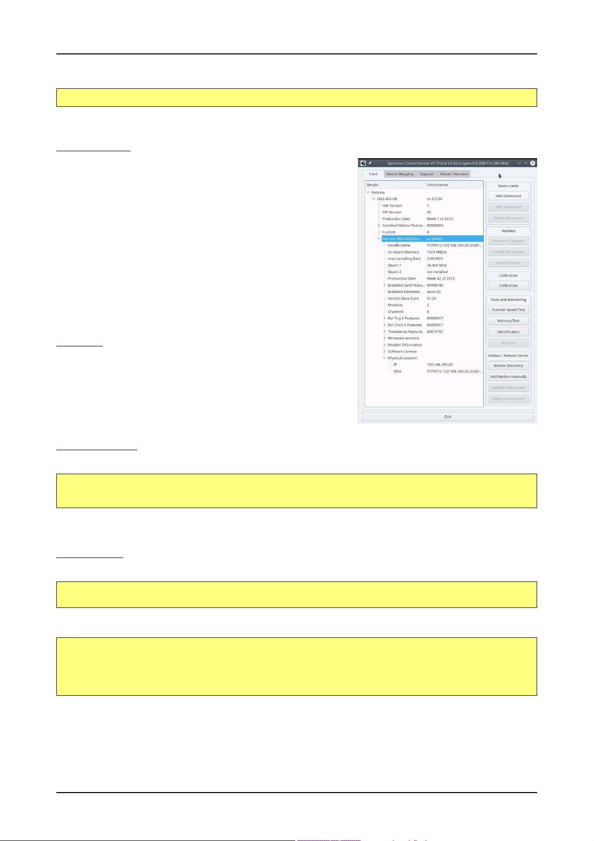
Linux Software Driver Installation
To access the driver library one must include the library in the compilation:
gcc -o test_prg -lspcm_linux test.cpp
To start programming the cards under Linux please use the standard C/C++ examples which are all running under Linux and Windows.
Control Center
The Spectrum Control Center is also available for Linux and needs to be installed separately. The features of the Control Center are described in a later chapter in deeper detail. The Control Center has been tested under all Linux distributions for which Spectrum
delivers pre-compiled kernel modules. The following packages need to be installed to run
the Control Center:
• X-Server
• expat
• freetype
• fontconfig
• libpng
• libspcm_linux (the Spectrum linux driver library)
Installation
Use the supplied packages in either *.deb or *.rpm format found in the driver section of
the CD by double clicking the package file root rights from a X-Windows window.
The Control Center is installed under KDE, Gnome or Unity in the system/system tools
section. It may be located directly in this menu or under a „More Programs“ menu. The
final location depends on the used Linux distribution. The program itself is installed as
/usr/bin/spcmcontrol and may be started directly from here.
Manual Installation
To manually install the Control Center, first extract the files from the rpm matching your distribution:
rpm2cpio spcmcontrol-{Version}.rpm > ~/spcmcontrol-{Version}.cpio
cd ~/
cpio -id < spcmcontrol-{Version}.cpio
You get the directory structure and the files contained in the rpm package. Copy the binary spcmcontrol to /usr/bin. Copy the .desktop file
to /usr/share/applications. Run ldconfig to update your systems library cache. Finally you can run spcmcontrol.
Troubleshooting
If you get a message like the following after starting spcmcontrol:
spcm_control: error while loading shared libraries: libz.so.1: cannot open shared object file: No such file
or directory
Run ldd spcm_control in the directory where spcm_control resides to see the dependencies of the program. The output may look like this:
libXext.so.6 => /usr/X11R6/lib/libXext.so.6 (0x4019e000)
libX11.so.6 => /usr/X11R6/lib/libX11.so.6 (0x401ad000)
libz.so.1 => not found
libdl.so.2 => /lib/libdl.so.2 (0x402ba000)
libpthread.so.0 => /lib/tls/libpthread.so.0 (0x402be000)
libstdc++.so.6 => /usr/lib/libstdc++.so.6 (0x402d0000)
As seen in the output, one of the libraries isn’t found inside the library cache of the system. Be sure that this library has been properly installed.
You may then run ldconfig. If this still doesn’t help please add the library path to /etc/ld.so.conf and run ldconfig again.
If the libspcm_linux.so is quoted as missing please make sure that you have installed the card driver properly before. If any other library is
stated as missing please install the matching package of your distribution.
30 M2i.30xx / M2i.30xx-exp Manual
Page 31

Software Software Overview
Software
This chapter gives you an overview about the structure of the drivers and the software, where to find and how to use the examples. It shows
in detail, how the drivers are included using different programming languages and deals with the differences when calling the driver functions
from them.
This manual only shows the use of the standard driver API. For further information on programming drivers
for third-party software like LabVIEW, MATLAB or IVI an additional manual is required that is available on
CD or by download on the internet.
Software Overview
The Spectrum drivers offer you a common and fast API for using all of the board hardware features. This API is the same on all supported
operating systems. Based on this API one can write own programs using any programming language that can access the driver API. This
manual describes in detail the driver API, providing you with the necessary information to write your own programs.
The drivers for third-party products like LabVIEW or MATLAB are also based on this API. The special functionality of these drivers is not subject
of this document and is described with separate manuals available on the CD or on the website.
Card Control Center
A special card control center is available on CD and from the internet for all Spectrum M2i/M3i/M4i/M4x/M2p cards and for all digitizerNETBOX or
generatorNETBOX products. Windows users find the Control Center installer on the
CD under „Install\win\spcmcontrol_install.exe“.
Linux users find the versions for the different stdc++ libraries under /Install/linux/spcm_control_center/ as RPM packages.
When using a digitizerNETBOX/generatorNETBOX the Card Control Center installers for Windows and Linux are also directly available from the integrated webserver.
The Control Center under Windows and Linux is available as an executive program.
Under Windows it is also linked as a system control and can be accessed directly
from the Windows control panel. Under Linux it is also available from the KDE System Settings, the Gnome or Unity Control Center. The different functions of the Spectrum card control center are explained in detail in the
following passages.
To install the Spectrum Control Center you will need to be logged in with administrator rights for your operating system. On all Windows versions, starting with Windows Vista, installations with enabled UAC will ask
you to start the installer with administrative rights (run as administrator).
(c) Spectrum GmbH 31
Page 32

Card Control Center Software
Discovery of Remote Cards and digitizerNETBOX/generatorNETBOX products
The Discovery function helps you to find and identify the Spectrum LXI
instruments like digitizerNETBOX/generatorNETBOX available to
your computer on the network. The Discovery function will also locate
Spectrum card products handled by an installed Spectrum Remote
Server somewhere on the network. The function is not needed if you
only have locally installed cards.
Please note that only remote products are found that are currently not
used by another program. Therefore in a bigger network the number
of Spectrum products found may vary depending on the current usage
of the products.
Execute the Discovery function by pressing the „Discovery“ button.
There is no progress window shown. After the discovery function has
been executed the remotely found Spectrum products are listed under
the node Remote as separate card level products. Inhere you find all
hardware information as shown in the next topic and also the needed
VISA resource string to access the remote card.
Please note that these information is also stored on your system and
allows Spectrum software like SBench 6 to access the cards directly
once found with the Discovery function.
After closing the control center and re-opening it the previously found
remote products are shown with the prefix cached, only showing the
card type and the serial number. This is the stored information that allows other Spectrum products to access previously found cards. Using
the „Update cached cards“ button will try to re-open these cards and gather information of it. Afterwards the remote cards may disappear if
they’re in use from somewhere else or the complete information of the remote products is shown again.
Enter IP Address of digitizerNETBOX/generatorNETBOX manually
If for some reason an automatic discovery is not suitable, such as the case where the remote
device is located in a different subnet, it can also be manually acessed by its type and IP address.
Wake On LAN of digitizerNETBOX/generatorNETBOX
Cached digitizerNETBOX/generatorNETBOX products that are currently in standby mode can
be woken up by using the „Wake remote device“ entry from the context menu.
The Control Center will broadcast a standard Wake On LAN „Magic Packet“, that is sent to the
device’s MAC address.
It is also possible to use any other Wake On LAN software to wake a digitizerNETBOX by sending such a „Magic Packet“ to the MAC address, which must be then entered manually.
It is also possible to wake a digitizerNETBOX/generatorNETBOX from your own application
software by using the SPC_NETBOX_WAKEONLAN register. To wake a
digitizerNETBOX/generatorNETBOX with the MAC address „00:03:2d:20:48“, the following
command can be issued:
spcm_dwSetParam_i64 (NULL, SPC_NETBOX_WAKEONLAN, 0x00032d2048ec);
32 M2i.30xx / M2i.30xx-exp Manual
Page 33

Software Card Control Center
Netbox Monitor
The Netbox Monitor permanently monitors whether the digitizerNETBOX/generatorNETBOX is still available through LAN. This tool is helpful
if the digitizerNETBOX is located somewhere in the company LAN or located remotely or directly mounted inside another device. Starting
the Netbox Monitor can be done in two different ways:
• Starting manually from the Spectrum Control Center using the context menu as shown above
• Starting from command line. The Netbox Monitor program is automatically installed together with the Spectrum Control Center and is
located in the selected install folder. Using the command line tool one can place a simple script into the autostart folder to have the Netbox Monitor running automatically after system boot. The command line tool needs the IP address of the
digitizerNETBOX/generatorNETBOX to monitor:
NetboxMonitor 192.168.169.22
The Netbox Monitor is shown as a small window with the type of digitizerNETBOX/generatorNETBOX in the title and the IP address under which it is accessed in the window itself. The Netbox Monitor runs completely independent of any other software and
can be used in parallel to any application software. The background of the IP address is used to display the current status of the
device. Pressing the Escape key or alt + F4 (Windows) terminates the Netbox Monitor permanently.
After starting the Netbox Monitor it is also displayed as a tray icon under Windows. The tray icon itself shows the status
of the digitizerNETBOX/generatorNETBOX as a color. Please note that the tray icon may be hidden as a Windows
default and need to be set to visible using the Windows tray setup.
Left clicking on the tray icon will hide/show the small Netbox Monitor status window. Right clicking on the tray icon as
shown in the picture on the right will open up a context menu. In here one can again select to hide/show the Netbox
Monitor status window, one can directly open the web interface from here or quit the program (including the tray icon)
completely.
The checkbox „Show Status Message“ controls whether the tray icon should emerge a status message on status change. If enabled (which is
default) one is notified with a status message if for example the LAN connection to the digitizerNETBOX/generatorNETBOX is lost.
The status colors:
• Green: digitizerNETBOX/generatorNETBOX available and accessible over LAN
• Cyan: digitizerNETBOX/generatorNETBOX is used from my computer
• Yellow: digitizerNETBOX/generatorNETBOX is used from a different computer
• Red: LAN connection failed, digitizerNETBOX/generatorNETBOX is no longer accessible
Hardware information
Through the control center you can easily get the main information
about all the installed Spectrum hardware. For each installed card
there is a separate tree of information available. The picture shows the
information for one installed card by example. This given information
contains:
• Basic information as the type of card, the production date and its
serial number, as well as the installed memory, the hardware revision of the base card, the number of available channels and
installed acquisition modules.
• Information about the maximum sampling clock and the available
quartz clock sources.
• The installed features/options in a sub-tree. The shown card is
equipped for example with the option Multiple Recording, Gated
Sampling, Timestamp and ABA-mode.
• Detailed Information concerning the installed acquisition modules.
In case of the shown analog acquisition card the information consists of the module’s hardware revision, of the converter resolution
and the last calibration date as well as detailed information on the
available analog input ranges, offset compensation capabilities
and additional features of the inputs.
(c) Spectrum GmbH 33
Page 34

Card Control Center Software
Firmware information
Another sub-tree is informing about the cards firmware version. As all Spectrum cards consist of several programmable
components, there is one firmware version per component.
Nearly all of the components firmware can be updated by
software. The only exception is the configuration device,
which only can receive a factory update.
The procedure on how to update the firmware of your Spectrum card with the help of the card control center is described
in a dedicated section later on.
The procedure on how to update the firmware of your
digitizerNETBOX/generatorNETBOX with the help of the integrated Webserver is described in a dedicated chapter later
on.
Software License information
This sub-tree is informing about installed possible software licenses.
As a default all cards come with the demo professional license of SBench6, that is limited to 30 starts of the software
with all professional features unlocked.
The number of demo starts left can be seen here.
34 M2i.30xx / M2i.30xx-exp Manual
Page 35
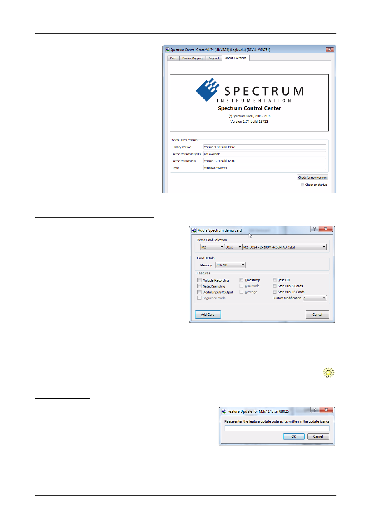
Software Card Control Center
Driver information
The Spectrum card control center also offers a way to
gather information on the installed and used Spectrum
driver.
The information on the driver is available through a dedicated tab, as the picture is showing in the example.
The provided information informs about the used type,
distinguishing between Windows or Linux driver and the
32 bit or 64 bit type.
It also gives direct information about the version of the
installed Spectrum kernel driver, separately for
M2i/M2iM3i cards and M4i/M4x/M2p cards and the
version of the library (which is the *.dll file under Windows).
The information given here can also be found under
Windows using the device manager form the
control panel. For details in driver details within the control panel please stick to the section on driver installation
in your hardware manual.
Installing and removing Demo cards
With the help of the card control center one can install demo cards
in the system. A demo card is simulated by the Spectrum driver including data production for acquisition cards. As the demo card is
simulated on the lowest driver level all software can be tested including SBench, own applications and drivers for third-party products
like LabVIEW. The driver supports up to 64 demo cards at the same
time. The simulated memory as well as the simulated software options can be defined when adding a demo card to the system.
Please keep in mind that these demo cards are only meant to test software and to show certain abilities of the software. They do not simulate the complete behavior of a card, especially not any timing
concerning trigger, recording length or FIFO mode notification. The
demo card will calculate data every time directly after been called
and give it to the user application without any more delay. As the
calculation routine isn’t speed optimized, generating demo data
may take more time than acquiring real data and transferring them
to the host PC.
Installed demo cards are listed together with the real hardware in the main information tree as described above. Existing demo cards can be
deleted by clicking the related button. The demo card details can be edited by using the edit button. It is for example possible to virtually
install additional feature to one card or to change the type to test with a different number of channels.
For installing demo cards on a system without real hardware simply run the Control Center installer. If the
installer is not detecting the necessary driver files normally residing on a system with real hardware, it will
simply install the Spcm_driver.
Feature upgrade
All optional features of the M2i/M3i/M4i/M4x cards that do not require any
hardware modifications can be installed on fielded cards. After Spectrum has received the order, the customer will get a personalized upgrade code. Just start the
card control center, click on „install feature“ and enter that given code. After a
short moment the feature will be installed and ready to use. No restart of the host
system is required.
For details on the available options and prices please contact your local Spectrum
distributor.
(c) Spectrum GmbH 35
Page 36

Card Control Center Software
Software License upgrade
The software license for SBench 6 Professional is installed on the hardware. If ordering a software license for a card that has already been delivered you will get an upgrade code to install that software license. The upgrade code will only match for that
particular card with the serial number given in the license. To install the software license please click the „Install SW License“ button and type in the code exactly as
given in the license.
Performing card calibration
The card control center also provides an easy way to access the
automatic card calibration routines of the Spectrum A/D converter cards. Depending on the used card family this can affect offset
calibration only or also might include gain calibration. Please refer to the dedicated chapter in your hardware manual for details.
Performing memory test
The complete on-board memory of the Spectrum M2i/M3i/M4i/M4x/M2p
cards can be tested by the memory test included with the card control center.
When starting the test, randomized data is generated and written to the onboard memory. After a complete write cycle all the data is read back and compared with the generated pattern.
Depending on the amount of installed on-board memory, and your computer’s
performance this operation might take a while.
Transfer speed test
The control center allows to measure the bus transfer
speed of an installed Spectrum card. Therefore different
setup is run multiple times and the overall bus transfer
speed is measured. To get reliable results it is necessary
that you disable debug logging as shown above. It is also
highly recommended that no other software or time-consuming background threads are running on that system.
The speed test program runs the following two tests:
• Repetitive Memory Transfers: single DMA data transfers are repeated and measured. This test simulates
the measuring of pulse repetition frequency when
doing multiple single-shots. The test is done using different block sizes. One can estimate the transfer in
relation to the transferred data size on multiple single-shots.
• FIFO mode streaming: this test measures the streaming speed in FIFO mode. The test can only use the same direction of transfer the card
has been designed for (card to PC=read for all DAQ cards, PC to card=write for all generator cards and both directions for I/O cards).
The streaming speed is tested without using the front-end to measure the maximum bus speed that can be reached.
The Speed in FIFO mode depends on the selected notify size which is explained later in this manual in greater detail.
The results are given in MB/s meaning MByte per second. To estimate whether a desired acquisition speed is possible to reach one has to
calculate the transfer speed in bytes. There are a few things that have to be put into the calculation:
• 12, 14 and 16 bit analog cards need two bytes for each sample.
• 16 channel digital cards need 2 bytes per sample while 32 channel digital cards need 4 bytes and 64 channel digital cards need 8
bytes.
• The sum of analog channels must be used to calculate the total transfer rate.
• The figures in the Speed Test Utility are given as MBytes, meaning 1024 * 1024 Bytes, 1 MByte = 1048576 Bytes
As an example running a card with 2 14 bit analog channels with 28 MHz produces a transfer rate of [2 channels * 2 Bytes/Sample *
28000000] = 112000000 Bytes/second. Taking the above figures measured on a standard 33 MHz PCI slot the system is just capable of
reaching this transfer speed: 108.0 MB/s = 108 * 1024 * 1024 = 113246208 Bytes/second.
Unfortunately it is not possible to measure transfer speed on a system without having a Spectrum card installed.
36 M2i.30xx / M2i.30xx-exp Manual
Page 37

Software Card Control Center
Debug logging for support cases
For answering your support questions as fast as possible, the
setup of the card, driver and firmware version and other information is very helpful.
Therefore the card control center provides an easy way to
gather all that information automatically.
Different debug log levels are available through the graphical interface. By default the log level is set to „no logging“ for
maximum performance.
The customer can select different log levels and the path of
the generated ASCII text file. One can also decide to delete the previous log file first before creating a new one automatically or to append
different logs to one single log file.
For maximum performance of your hardware, please make sure that the debug logging is set to „no logging“ for normal operation. Please keep in mind that a detailed logging in append mode can quickly generate huge log files.
Device mapping
Within the „Device mapping“ tab of the Spectrum Control Center, one can enable the re-mapping of Spectrum devices, be it either local cards, remote instruments such as a digitizerNETBOX or generatorNETBOX or even cards in a
remote PC and accessed via the Spectrum remote server option.
In the left column the re-mapped device name is visible that is given to the device
in the right column with its original un-mapped device string.
In this example the two local cards „spcm0“ and „spcm1“ are re-mapped to
„spcm1“ and „spcm0“ respectively, so that their names are simply swapped.
The remote digitizerNETBOX device is mapped to spcm2.
The application software can then use the re-mapped name for simplicity instead
of the quite long VISA string.
Changing the order of devices within one group (either local cards or remote
devices) can simply be accomplished by draging&dropping the cards to their
desired position in the same table.
(c) Spectrum GmbH 37
Page 38

Compatibility Layer (M2i cards only) Software
Firmware upgrade
One of the major features of the card control center is the ability to update
the card’s firmware by an easy-to-use software. The latest firmware revisions can be found in the download section of our homepage under
www.spectrum-instrumentation.com.
A new firmware version is provided there as an installer, that copies the
latest firmware to your system. All files are located in a dedicated subfolder „FirmwareUpdate“ that will be created inside the Spectrum installation
folder. Under Windows this folder by default has been created in the standard program installation directory.
Please do the following steps when wanting to update the firmware of
your M2i/M3i/M4i/M4x/M2p card:
• Download the latest software driver for your operating system provided on the Spectrum homepage.
• Install the new driver as described in the driver install section of your
hardware manual provided with the card. All manuals can also be
found on the Spectrum homepage in the literature download section.
• Download and run the latest Spectrum Control Center installer.
• Download the installer for the new firmware version.
• Start the installer and follow the instructions given there.
• Start the card control center, select the „card“ tab, select the card from
the listbox and press the „firmware update“ button on the right side.
The dialog then will inform you about the currently installed firmware version for the different devices on the card and the new versions that are
available. All devices that will be affected with the update are marked as „update needed“. Simply start the update or cancel the operation
now, as a running update cannot be aborted.
Please keep in mind that you have to start the update for each card installed in your system separately.
Select one card after the other from the listbox and press the „firmware update“ button. The firmware installer on the other hand only needs to be started once prior to the update.
Do not abort or shut down the computer while the firmware update is in progress. After a successful update
please shut down your PC completely. The re-powering is required to finally activate the new firmware version of your Spectrum card.
Compatibility Layer (M2i cards only)
The installation of the M2i driver also installs a special compatibility DLL (under Windows). This dll allows the use of the M2i cards with
software that has been build for the corresponding MI cards. The compatibility dll is installed in the Windows system directory under the
name spectrum_comp.dll. There are two ways to use the compatibility dll:
Usage modes
• Re-compile the old application software and including the new library
spectrum_comp.lib that is delivered
with the compatibility DLL. This is the
recommended usage. The new compatibility DLL now has control of the
older driver for MI, MC and MX drivers as well as of the newer driver for
the M2i cards. The newly compiled
program is now capable of running
with old cards as well as with new
cards without any further changes. The
compatibility DLL will examine the system and support both card types as
they are found. Any driver updates of
either the older MI cards or the newer
M2i will just update the correct part of
the system. SBench 5 uses this mode
and is therefore capable of supporting
38 M2i.30xx / M2i.30xx-exp Manual
Page 39

Software Accessing the hardware with SBench 6
all card types although it was never programmed to support the M2i natively.
• If for any reason a re-compile of the existing program is not possible one can simply rename the compatibility DLL spectrum_comp.dll to
spectrum.dll and copy it over the existing spectrum.dll in the Windows system directory. The program won’t notice that a different DLL is
used and uses the newly installed M2i card. Unfortunately a shared access to either MI or M2i is not possible using this method.
Abilities and Limitations of the compatibility DLL
The compatibility layer has been done to help you migrating software for the M2i cards and tries to hide the new hardware to older program
as best as possible. However as there are some basic differences between both hardware families not everything can be simulated. The
following list should give you an overview of some aspects of the compatibility layer:
• The data transfer is reorganized internally but still uses the same application data buffers. No data is copied for the data transfers. Therefore the transfer speed that one will gain is the full transfer speed of the M2i card series which is between 20% and 130% faster than the
one of the MI series.
• As the compatibility layer tries to hide the new driver as much as possible none of the new or improved features are available to older
programs. If you need to use a new feature please use the new driver.
• The M2i driver checks the given parameters very carefully while the older driver was sometimes a little lazy and some false commands
and driver parameters weren’t noticed or were noticed but didn’t lock the driver. The M2i will check every register settings at every time
and lock the driver if an error occurs. It may be necessary to fix the application code for handling this more strict error checking.
• The compatibility DLL doesn’t support all special features that have been added to the MI series over the years as some of them are discontinued in the new hardware. As long as the application program sticks to the main features this won’t be a problem.
• The compatibility DLL does not add any delays from the MI series as the M2i series has been optimized for small delays. As an example,
the MI cards had a fixed delay from trigger to first sample when using Multiple Recording. The M2i cards now have a programmable pretrigger size. When using the compatibility layer this pretrigger is set to the minimum and data will be visible before the trigger event.
• Although the application software doesn’t see a difference between old an new cards there is no chance to synchronize both card types
together as the synchronization option uses different connectors, different signals and different timing.
Accessing the hardware with SBench 6
After the installation of the cards and the drivers it can be useful to first test
the card function with a ready to run software before starting with programming. If accessing a digitizerNETBOX/generatorNETBOX a full SBench 6
Professional license is installed on the system and can be used without any
limitations. For plug-in card level products a base version of SBench 6 is delivered with the card on CD also including a 30 starts Professional demo
version for plain card products. If you already have bought a card prior to
the first SBench 6 release please contact your local dealer to get a SBench
6 Professional demo version.
SBench 6 supports all current acquisition and generation cards and digitizerNETBOX/generatorNETBOX products from Spectrum. Depending on the
used product and the software setup, one can use SBench as a digital storage oscilloscope, a spectrum analyzer, a logic analyzer or simply as a data
recording front end. Different export and import formats allow the use of
SBench 6 together with a variety of other programs.
On the CD you’ll find an install version of SBench 6 in the directory /Install/SBench6. The current version of SBench 6 is available free of charge
directly from the Spectrum website www.spectrum-instrumentation.com.
the digitizerNETBOX/generatorNETBOX, a SBench 6 version is also available on the webpages of the digitizerNETBOX/generatorNETBOX.
SBench 6 has been designed to run under Windows 7, Windows 8 and Windows 10 as well as Linux using KDE, Gnome or Unity Desktop.
Please go to the download section and get the latest version there. If using
C/C++ Driver Interface
C/C++ is the main programming language for which the drivers have been designed for. Therefore the interface to C/C++ is the best match.
All the small examples of the manual showing different parts of the hardware programming are done with C. As the libraries offer a standard
interface it is easy to access the libraries also with other programming languages like Delphi, Basic, Python or Java . Please read the following
chapters for additional information on this.
(c) Spectrum GmbH 39
Page 40

C/C++ Driver Interface Software
Header files
The basic task before using the driver is to include the header files that are delivered on CD together with the board. The header files are
found in the directory /Driver/c_header. Please don’t change them in any way because they are updated with each new driver version to
include the new registers and new functionality.
dlltyp.h Includes the platform specific definitions for data types and function declarations. All data types are based on these definitions. The use of this type definition
regs.h Defines all registers and commands which are used in the Spectrum driver for the different boards. The registers a board uses are described in the board spe-
spcm_drv.h Defines the functions of the used SpcM driver. All definitions are taken from the file dlltyp.h. The functions themselves are described below.
spcerr.h Contains all error codes used with the Spectrum driver. All error codes that can be given back by any of the driver functions are also described here briefly. The
file allows the use of examples and programs on different platforms without changes to the program source. The header file supports Microsoft Visual C++, Borland C++ Builder and GNU C/C++ directly. When using other compilers it might be necessary to make a copy of this file and change the data types according to this compiler.
cific part of the documentation. This header file is common for all cards. Therefore this file also contains a huge number of registers used on other card types
than the one described in this manual. Please stick to the manual to see which registers are valid for your type of card.
error codes and their meaning are described in detail in the appendix of this manual.
Example for including the header files:
// ----- driver includes ----#include "dlltyp.h" // 1st include
#include "regs.h" // 2nd include
#include "spcerr.h" // 3rd include
#include "spcm_drv.h" // 4th include
Please always keep the order of including the four Spectrum header files. Otherwise some or all of the functions do not work properly or compiling your program will be impossible!
General Information on Windows 64 bit drivers
After installation of the Spectrum 64 bit driver there are two general ways to access the hardware and to develop applications. If you’re going to develop a real 64 bit application it is necessary to access the 64 bit
driver dll (spcm_win64.dll) as only this driver dll is supporting the full 64 bit address range.
But it is still possible to run 32 bit applications or to develop 32 bit applications even under Windows 64 bit.
Therefore the 32 bit driver dll (spcm_win32.dll) is also installed in the system. The Spectrum SBench5 software
is for example running under Windows 64 bit using this driver. The 32 bit dll of course only offers the 32 bit
address range and is therefore limited to access only 4 GByte of memory. Beneath both drivers the 64 bit kernel driver is running.
Mixing of 64 bit application with 32 bit dll or vice versa is not possible.
Microsoft Visual C++ 6.0, 2005 and newer 32 Bit
Include Driver
The driver files can be directly included in Microsoft C++ by simply using the library file spcm_win32_msvcpp.lib that is delivered together
with the drivers. The library file can be found on the CD in the path /examples/c_cpp/c_header. Please include the library file in your Visual
C++ project as shown in the examples. All functions described below are now available in your program.
Examples
Examples can be found on CD in the path /examples/c_cpp. This directory includes a number of different examples that can be used with
any card of the same type (e.g. A/D acquisition cards, D/A acquisition cards). You may use these examples as a base for own programming
and modify them as you like. The example directories contain a running workspace file for Microsoft Visual C++ 6.0 (*.dsw) as well as project
files for Microsoft Visual Studio 2005 and newer (*.vcproj) that can be directly loaded or imported and compiled.
There are also some more board type independent examples in separate subdirectory. These examples show different aspects of the cards
like programming options or synchronization and can be combined with one of the board type specific examples.
As the examples are build for a card class there are some checking routines and differentiation between cards families. Differentiation aspects
can be number of channels, data width, maximum speed or other details. It is recommended to change the examples matching your card
type to obtain maximum performance. Please be informed that the examples are made for easy understanding and simple showing of one
aspect of programming. Most of the examples are not optimized for maximum throughput or repetition rates.
Microsoft Visual C++ 2005 and newer 64 Bit
Depending on your version of the Visual Studio suite it may be necessary to install some additional 64 bit components (SDK) on your system.
Please follow the instructions found on the MSDN for further information.
Include Driver
The driver files can be directly included in Microsoft C++ by simply using the library file spcm_win64_msvcpp.lib that is delivered together
with the drivers. The library file can be found on the CD in the path /examples/c_cpp/c_header. All functions described below are now
available in your program.
40 M2i.30xx / M2i.30xx-exp Manual
Page 41

Software C/C++ Driver Interface
C++ Builder 32 Bit
Include Driver
The driver files can be easily included in C++ Builder by simply using the library file spcm_win32_bcppb.lib that is delivered together with
the drivers. The library file can be found on the CD in the path /examples/c_cpp/c_header. Please include the library file in your C++ Builder
project as shown in the examples. All functions described below are now available in your program.
Examples
The C++ Builder examples share the sources with the Visual C++ examples. Please see above chapter for a more detailed documentation of
the examples. In each example directory are project files for Visual C++ as well as C++ Builder.
Linux Gnu C/C++ 32/64 Bit
Include Driver
The interface of the linux drivers does not differ from the windows interface. Please include the spcm_linux.lib library in your makefile to have
access to all driver functions. A makefile may look like this:
COMPILER = gcc
EXECUTABLE = test_prg
LIBS = -lspcm_linux
OBJECTS = test.o\
test2.o
all: $(EXECUTABLE)
$(EXECUTABLE): $(OBJECTS)
$(COMPILER) $(CFLAGS) -o $(EXECUTABLE) $(LIBS) $(OBJECTS)
%.o: %.cpp
$(COMPILER) $(CFLAGS) -o $*.o -c $*.cpp
Examples
The Gnu C/C++ examples share the source with the Visual C++ examples. Please see above chapter for a more detailed documentation of
the examples. Each example directory contains a makefile for the Gnu C/C++ examples.
C++ for .NET
Please see the next chapter for more details on the .NET inclusion.
Other Windows C/C++ compilers 32 Bit
Include Driver
To access the driver, the driver functions must be loaded from the 32 bit driver DLL. Most compilers offer special tools to generate a matching
library (e.g. Borland offers the implib tool that generates a matching library out of the windows driver DLL). If such a tool is available it is
recommended to use it. Otherwise the driver functions need to be loaded from the dll using standard Windows functions. There is one example in the example directory /examples/c_cpp/dll_loading that shows the process.
Example of function loading:
hDLL = LoadLibrary ("spcm_win32.dll"); // Load the 32 bit version of the Spcm driver
pfn_spcm_hOpen = (SPCM_HOPEN*) GetProcAddress (hDLL, "_spcm_hOpen@4");
pfn_spcm_vClose = (SPCM_VCLOSE*) GetProcAddress (hDLL, "_spcm_vClose@4");
Other Windows C/C++ compilers 64 Bit
Include Driver
To access the driver, the driver functions must be loaded from the 64 bit the driver DLL. Most compilers offer special tools to generate a matching library (e.g. Borland offers the implib tool that generates a matching library out of the windows driver DLL). If such a tool is available it
is recommended to use it. Otherwise the driver functions need to be loaded from the dll using standard Windows functions. There is one
example in the example directory /examples/c_cpp/dll_loading that shows the process for 32 bit environments. The only line that needs to
be modified is the one loading the DLL:
Example of function loading:
hDLL = LoadLibrary ("spcm_win64.dll"); // Modified: Load the 64 bit version of the Spcm driver here
pfn_spcm_hOpen = (SPCM_HOPEN*) GetProcAddress (hDLL, "spcm_hOpen");
pfn_spcm_vClose = (SPCM_VCLOSE*) GetProcAddress (hDLL, "spcm_vClose");
(c) Spectrum GmbH 41
Page 42

Driver functions Software
National Instruments LabWindows/CVI
Include Drivers
To use the Spectrum driver under LabWindows/CVI it is necessary to first load the functions from the driver dll. Please use the library file
spcm_win32_cvi.lib to access the driver functions.
Examples
Examples for LabWindows/CVI can be found on CD in the directory /examples/cvi. Please mix these examples with the standard C/C++
examples to have access to all functions and modes of the cards.
Driver functions
The driver contains seven main functions to access the hardware.
Own types used by our drivers
To simplify the use of the header files and our examples with different platforms and compilers and to avoid any implicit type conversions we
decided to use our own type declarations. This allows us to use platform independent and universal examples and driver interfaces. If you
do not stick to these declarations please be sure to use the same data type width. However it is strongly recommended that you use our defined
type declarations to avoid any hard to find errors in your programs. If you’re using the driver in an environment that is not natively supported
by our examples and drivers please be sure to use a type declaration that represents a similar data width
Declaration Type Declaration Type
int8 8 bit signed integer (range from -128 to +127) uint8 8 bit unsigned integer (range from 0 to 255)
int16 16 bit signed integer (range from -32768 to 32767) uint16 16 bit unsigned integer (range from 0 to 65535)
int32 32 bit signed integer (range from -2147483648 to 2147483647) uint32 32 bit unsigned integer (range from 0 to 4294967295)
int64 64 bit signed integer (full range) uint64 64 bit unsigned integer (full range)
drv_handle handle to driver, implementation depends on operating system platform
Notation of variables and functions
In our header files and examples we use a common and reliable form of notation for variables and functions. Each name also contains the
type as a prefix. This notation form makes it easy to see implicit type conversions and minimizes programming errors that result from using
incorrect types. Feel free to use this notation form for your programs also-
Declaration Notation Declaration Notation
int8 byName (byte) uint8 cName (character)
int16 nName uint16 wName (word)
int32 lName (long) uint32 dwName (double word)
int64 llName (long long) uint64 qwName (quad word)
int32* plName (pointer to long) char szName (string with zero termination)
Function
spcm_hOpen
This function initializes and opens an installed card supporting the new SpcM driver interface. At the time of printing this manual this are all
cards of the M2i/M3i/M4i/M4x cards and digitizerNETBOX/generatorNETBOX devices. The function returns a handle that has to be used
for driver access. If the card can’t be found or the loading of the driver generated an error the function returns a NULL. When calling this
function all card specific installation parameters are read out from the hardware and stored within the driver. It is only possible to open one
device by one software as concurrent hardware access may be very critical to system stability. As a result when trying to open the same
device twice an error will be raised and the function returns NULL.
Function spcm_hOpen (const char* szDeviceName):
drv_handle _stdcall spcm_hOpen ( // tries to open the device and returns handle or error code
const char* szDeviceName); // name of the device to be opened
Under Linux the device name in the function call needs to be a valid device name. Please change the string according to the location of the
device if you don’t use the standard Linux device names. The driver is installed as default under /dev/spcm0, /dev/spcm1 and so on. The
kernel driver numbers the devices starting with 0.
Under Windows the only part of the device name that is used is the tailing number. The rest of the device name is ignored. Therefore to keep
the examples simple we use the Linux notation in all our examples. The tailing number gives the index of the device to open. The Windows
kernel driver numbers all devices that it finds on boot time starting with 0.
Example for local installed cards
drv_handle hDrv; // returns the handle to the opended driver or NULL in case of error
hDrv = spcm_hOpen ("/dev/spcm0"); // string to the driver to open
if (!hDrv)
printf (“open of driver failed\n”);
42 M2i.30xx / M2i.30xx-exp Manual
Page 43

Software Driver functions
Example for digitizerNETBOX/generatorNETBOX and remote installed cards
drv_handle hDrv; // returns the handle to the opended driver or NULL in case of error
hDrv = spcm_hOpen ("TCPIP::192.168.169.14::INST0::INSTR");
if (!hDrv)
printf (“open of driver failed\n”);
If the function returns a NULL it is possible to read out the error description of the failed open function by simply passing this NULL to the error
function. The error function is described in one of the next topics.
Function spcm_vClose
This function closes the driver and releases all allocated resources. After closing the driver handle it is not possible to access this driver any
more. Be sure to close the driver if you don’t need it any more to allow other programs to get access to this device.
Function spcm_vClose:
void _stdcall spcm_vClose ( // closes the device
drv_handle hDevice); // handle to an already opened device
Example:
spcm_vClose (hDrv);
Function spcm_dwSetParam
All hardware settings are based on software registers that can be set by one of the functions spcm_dwSetParam. These functions set a register
to a defined value or execute a command. The board must first be initialized by the spcm_hOpen function. The parameter lRegister must have
a valid software register constant as defined in regs.h. The available software registers for the driver are listed in the board specific part of
the documentation below. The function returns a 32 bit error code if an error occurs. If no error occurs the function returns ERR_OK, what is
zero.
Function spcm_dwSetParam
uint32 _stdcall spcm_dwSetParam_i32 ( // Return value is an error code
drv_handle hDevice, // handle to an already opened device
int32 lRegister, // software register to be modified
int32 lValue); // the value to be set
uint32 _stdcall spcm_dwSetParam_i64m ( // Return value is an error code
drv_handle hDevice, // handle to an already opened device
int32 lRegister, // software register to be modified
int32 lValueHigh, // upper 32 bit of the value. Containing the sign bit !
uint32 dwValueLow); // lower 32 bit of the value.
uint32 _stdcall spcm_dwSetParam_i64 ( // Return value is an error code
drv_handle hDevice, // handle to an already opened device
int32 lRegister, // software register to be modified
int64 llValue); // the value to be set
Example:
if (spcm_dwSetParam_i32 (hDrv, SPC_MEMSIZE, 16384) != ERR_OK)
printf (“Error when setting memory size\n”);
This example sets the memory size to 16 kSamples (16384). If an error occurred the example will show a short error message
Function
spcm_dwGetParam
All hardware settings are based on software registers that can be read by one of the functions spcm_dwGetParam. These functions read an
internal register or status information. The board must first be initialized by the spcm_hOpen function. The parameter lRegister must have a
valid software register constant as defined in the regs.h file. The available software registers for the driver are listed in the board specific part
of the documentation below. The function returns a 32 bit error code if an error occurs. If no error occurs the function returns ERR_OK, what
is zero.
(c) Spectrum GmbH 43
Page 44

Driver functions Software
Function spcm_dwGetParam
uint32 _stdcall spcm_dwGetParam_i32 ( // Return value is an error code
drv_handle hDevice, // handle to an already opened device
int32 lRegister, // software register to be read out
int32* plValue); // pointer for the return value
uint32 _stdcall spcm_dwGetParam_i64m ( // Return value is an error code
drv_handle hDevice, // handle to an already opened device
int32 lRegister, // software register to be read out
int32* plValueHigh, // pointer for the upper part of the return value
uint32* pdwValueLow); // pointer for the lower part of the return value
uint32 _stdcall spcm_dwGetParam_i64 ( // Return value is an error code
drv_handle hDevice, // handle to an already opened device
int32 lRegister, // software register to be read out
int64* pllValue); // pointer for the return value
Example:
int32 lSerialNumber;
spcm_dwGetParam_i32 (hDrv, SPC_PCISERIALNO, &lSerialNumber);
printf (“Your card has serial number: %05d\n”, lSerialNumber);
The example reads out the serial number of the installed card and prints it. As the serial number is available under all circumstances there is
no error checking when calling this function.
Different call types of spcm_dwSetParam and spcm_dwGetParam: _i32, _i64, _i64m
The three functions only differ in the type of the parameters that are used to call them. As some of the registers can exceed the 32 bit integer
range (like memory size or post trigger) it is recommended to use the _i64 function to access these registers. However as there are some
programs or compilers that don’t support 64 bit integer variables there are two functions that are limited to 32 bit integer variables. In case
that you do not access registers that exceed 32 bit integer please use the _i32 function. In case that you access a register which exceeds 64
bit value please use the _i64m calling convention. Inhere the 64 bit value is split into a low double word part and a high double word part.
Please be sure to fill both parts with valid information.
If accessing 64 bit registers with 32 bit functions the behavior differs depending on the real value that is currently located in the register.
Please have a look at this table to see the different reactions depending on the size of the register:
Internal register read/write Function type Behavior
32 bit register read spcm_dwGetParam_i32 value is returned as 32 bit integer in plValue
32 bit register read spcm_dwGetParam_i64 value is returned as 64 bit integer in pllValue
32 bit register read spcm_dwGetParam_i64m value is returned as 64 bit integer, the lower part in plValueLow, the upper part in plValueHigh. The upper part can
32 bit register write spcm_dwSetParam_i32 32 bit value can be directly written
32 bit register write spcm_dwSetParam_i64 64 bit value can be directly written, please be sure not to exceed the valid register value range
32 bit register write spcm_dwSetParam_i64m 32 bit value is written as llValueLow, the value llValueHigh needs to contain the sign extension of this value. In case
64 bit register read spcm_dwGetParam_i32 If the internal register has a value that is inside the 32 bit integer range (-2G up to (2G - 1)) the value is returned
64 bit register read spcm_dwGetParam_i64 value is returned as 64 bit integer value in pllValue independent of the value of the internal register.
64 bit register read spcm_dwGetParam_i64m the internal value is split into a low and a high part. As long as the internal value is within the 32 bit range, the low
64 bit register write spcm_dwSetParam_i32 the value to be written is limited to 32 bit range. If a value higher than the 32 bit range should be written, one of
64 bit register write spcm_dwSetParam_i64 the value has to be split into two parts. Be sure to fill the upper part lValueHigh with the correct sign extension even
64 bit register write spcm_dwSetParam_i64m the value can be written directly independent of the size.
Function
spcm_dwGetContBuf
be ignored as it’s only a sign extension
of llValueLow being a value >= 0 llValueHigh can be 0, in case of llValueLow being a value < 0, llValueHigh has to
be -1.
normally. If the internal register exceeds this size an error code ERR_EXCEEDSINT32 is returned. As an example:
reading back the installed memory will work as long as this memory is < 2 GByte. If the installed memory is >= 2
GByte the function will return an error.
part plValueLow contains the 32 bit value and the upper part plValueHigh can be ignored. If the internal value
exceeds the 32 bit range it is absolutely necessary to take both value parts into account.
the other function types need to used.
if you only write a 32 bit value as the driver every time interprets both parts of the function call.
This function reads out the internal continuous memory buffer in bytes, in case one has been allocated. If no buffer has been allocated the
function returns a size of zero and a NULL pointer. You may use this buffer for data transfers. As the buffer is continuously allocated in memory
44 M2i.30xx / M2i.30xx-exp Manual
Page 45

Software Driver functions
the data transfer will speed up by up to 15% - 25%, depending on your specific kind of card. Please see further details in the appendix of
this manual.
uint32 _stdcall spcm_dwGetContBuf_i64 ( // Return value is an error code
drv_handle hDevice, // handle to an already opened device
uint32 dwBufType, // type of the buffer to read as listed above under SPCM_BUF_XXXX
void** ppvDataBuffer, // address of available data buffer
uint64* pqwContBufLen); // length of available continuous buffer
uint32 _stdcall spcm_dwGetContBuf_i64m (// Return value is an error code
drv_handle hDevice, // handle to an already opened device
uint32 dwBufType, // type of the buffer to read as listed above under SPCM_BUF_XXXX
void** ppvDataBuffer, // address of available data buffer
uint32* pdwContBufLenH, // high part of length of available continuous buffer
uint32* pdwContBufLenL); // low part of length of available continuous buffer
These functions have been added in driver version 1.36. The functions are not available in older driver versions.
These functions also only have effect on locally installed cards and are neither useful nor usable with any
digitizerNETBOX or generatorNETBOX products, because no local kernel driver is involved in such a setup.
For remote devices these functions will return a NULL pointer for the buffer and 0 Bytes in length.
Function
spcm_dwDefTransfer
The spcm_dwDefTransfer function defines a buffer for a following data transfer. This function only defines the buffer, there is no data transfer
performed when calling this function. Instead the data transfer is started with separate register commands that are documented in a later
chapter. At this position there is also a detailed description of the function parameters.
Please make sure that all parameters of this function match. It is especially necessary that the buffer address is a valid address pointing to
memory buffer that has at least the size that is defined in the function call. Please be informed that calling this function with non valid parameters may crash your system as these values are base for following DMA transfers.
The use of this function is described in greater detail in a later chapter.
Function spcm_dwDefTransfer
uint32 _stdcall spcm_dwDefTransfer_i64m(// Defines the transfer buffer by 2 x 32 bit unsigned integer
drv_handle hDevice, // handle to an already opened device
uint32 dwBufType, // type of the buffer to define as listed above under SPCM_BUF_XXXX
uint32 dwDirection, // the transfer direction as defined above
uint32 dwNotifySize, // no. of bytes after which an event is sent (0=end of transfer)
void* pvDataBuffer, // pointer to the data buffer
uint32 dwBrdOffsH, // high part of offset in board memory
uint32 dwBrdOffsL, // low part of offset in board memory
uint32 dwTransferLenH, // high part of transfer buffer length
uint32 dwTransferLenL); // low part of transfer buffer length
uint32 _stdcall spcm_dwDefTransfer_i64 (// Defines the transfer buffer by using 64 bit unsigned integer values
drv_handle hDevice, // handle to an already opened device
uint32 dwBufType, // type of the buffer to define as listed above under SPCM_BUF_XXXX
uint32 dwDirection, // the transfer direction as defined above
uint32 dwNotifySize, // no. of bytes after which an event is sent (0=end of transfer)
void* pvDataBuffer, // pointer to the data buffer
uint64 qwBrdOffs, // offset for transfer in board memory
uint64 qwTransferLen); // buffer length
This function is available in two different formats as the spcm_dwGetParam and spcm_dwSetParam functions are. The background is the
same. As long as you’re using a compiler that supports 64 bit integer values please use the _i64 function. Any other platform needs to use
the _i64m function and split offset and length in two 32 bit words.
Example:
int16* pnBuffer = new int16[8192];
if (spcm_dwDefTransfer_i64 (hDrv, SPCM_BUF_DATA, SPCM_DIR_CARDTOPC, 0, (void*) pnBuffer, 0, 16384) != ERR_OK)
printf (“DefTransfer failed\n”);
The example defines a data buffer of 8 kSamples of 16 bit integer values = 16 kByte (16384 byte) for a transfer from card to PC memory.
As notify size is set to 0 we only want to get an event when the transfer has finished.
Function spcm_dwInvalidateBuf
The invalidate buffer function is used to tell the driver that the buffer that has been set with spcm_dwDefTransfer call is no longer valid. It is
necessary to use the same buffer type as the driver handles different buffers at the same time. Call this function if you want to delete the buffer
memory after calling the spcm_dwDefTransfer function. If the buffer already has been transferred after calling spcm_dwDefTransfer it is not
necessary to call this function. When calling spcm_dwDefTransfer any further defined buffer is automatically invalidated.
(c) Spectrum GmbH 45
Page 46

Driver functions Software
Function spcm_dwInvalidateBuf
uint32 _stdcall spcm_dwInvalidateBuf ( // invalidate the transfer buffer
drv_handle hDevice, // handle to an already opened device
uint32 dwBufType); // type of the buffer to invalidate as
// listed above under SPCM_BUF_XXXX
Function spcm_dwGetErrorInfo
The function returns complete error information on the last error that has occurred. The error handling itself is explained in a later chapter in
greater detail. When calling this function please be sure to have a text buffer allocated that has at least ERRORTEXTLEN length. The error text
function returns a complete description of the error including the register/value combination that has raised the error and a short description
of the error details. In addition it is possible to get back the error generating register/value for own error handling. If not needed the buffers
for register/value can be left to NULL.
Note that the timeout event (ERR_TIMEOUT) is not counted as an error internally as it is not locking the driver
but as a valid event. Therefore the GetErrorInfo function won’t return the timeout event even if it had occurred
in between. You can only recognize the ERR_TIMEOUT as a direct return value of the wait function that was
called.
Function spcm_dwGetErrorInfo
uint32 _stdcall spcm_dwGetErrorInfo_i32 (
drv_handle hDevice, // handle to an already opened device
uint32* pdwErrorReg, // address of the error register (can be zero if not of interest)
int32* plErrorValue, // address of the error value (can be zero if not of interest)
char pszErrorTextBuffer[ERRORTEXTLEN]); // text buffer for text error
Example:
char szErrorBuf[ERRORTEXTLEN];
if (spcm_dwSetParam_i32 (hDrv, SPC_MEMSIZE, -1))
{
spcm_dwGetErrorInfo_i32 (hDrv, NULL, NULL, szErrorBuf);
printf (“Set of memsize failed with error message: %s\n”, szErrorBuf);
}
46 M2i.30xx / M2i.30xx-exp Manual
Page 47

Software Delphi (Pascal) Programming Interface
Delphi (Pascal) Programming Interface
Driver interface
The driver interface is located in the sub-directory d_header and contains the following files. The files need to be included in the delphi project
and have to be put into the „uses“ section of the source files that will access the driver. Please do not edit any of these files as they’re regularly
updated if new functions or registers have been included.
file spcm_win32.pas
The file contains the interface to the driver library and defines some needed constants and variable types. All functions of the delphi library
are similar to the above explained standard driver functions:
// ----- device handling functions ----function spcm_hOpen (strName: pchar): int32; stdcall; external 'spcm_win32.dll' name '_spcm_hOpen@4';
procedure spcm_vClose (hDevice: int32); stdcall; external 'spcm_win32.dll' name '_spcm_vClose@4';
function spcm_dwGetErrorInfo_i32 (hDevice: int32; var lErrorReg, lErrorValue: int32; strError: pchar): uint32;
stdcall; external 'spcm_win32.dll' name '_spcm_dwGetErrorInfo_i32@16'
// ----- register access functions ----function spcm_dwSetParam_i32 (hDevice, lRegister, lValue: int32): uint32;
stdcall; external 'spcm_win32.dll' name '_spcm_dwSetParam_i32@12';
function spcm_dwSetParam_i64 (hDevice, lRegister: int32; llValue: int64): uint32;
stdcall; external 'spcm_win32.dll' name '_spcm_dwSetParam_i64@16';
function spcm_dwGetParam_i32 (hDevice, lRegister: int32; var plValue: int32): uint32;
stdcall; external 'spcm_win32.dll' name '_spcm_dwGetParam_i32@12';
function spcm_dwGetParam_i64 (hDevice, lRegister: int32; var pllValue: int64): uint32;
stdcall; external 'spcm_win32.dll' name '_spcm_dwGetParam_i64@12';
// ----- data handling ----function spcm_dwDefTransfer_i64 (hDevice, dwBufType, dwDirection, dwNotifySize: int32; pvDataBuffer: Pointer;
llBrdOffs, llTransferLen: int64): uint32;
stdcall; external 'spcm_win32.dll' name '_spcm_dwDefTransfer_i64@36';
function spcm_dwInvalidateBuf (hDevice, lBuffer: int32): uint32;
stdcall; external 'spcm_win32.dll' name '_spcm_dwInvalidateBuf@8';
The file also defines types used inside the driver and the examples. The types have similar names as used under C/C++ to keep the examples
more simple to understand and allow a better comparison.
file SpcRegs.pas
The SpcRegs.pas file defines all constants that are used for the driver. The constant names are the same names as used under the C/C++
examples. All constants names will be found throughout this hardware manual when certain aspects of the driver usage are explained. It is
recommended to only use these constant names for better visibility of the programs:
const SPC_M2CMD = 100; { write a command }
const M2CMD_CARD_RESET = $00000001; { hardware reset }
const M2CMD_CARD_WRITESETUP = $00000002; { write setup only }
const M2CMD_CARD_START = $00000004; { start of card (including writesetup) }
const M2CMD_CARD_ENABLETRIGGER = $00000008; { enable trigger engine }
...
file SpcErr.pas
The SpeErr.pas file contains all error codes that may be returned by the driver.
Including the driver files
To use the driver function and all the defined constants it is necessary to include the files into the project as
shown in the picture on the right. The project overview is taken from one of the examples delivered on CD.
Besides including the driver files in the project it is also necessary to include them in the uses section of the
source files where functions or constants should be used:
uses
Windows, Messages, SysUtils, Classes, Graphics, Controls, Forms, Dialogs,
StdCtrls, ExtCtrls,
SpcRegs, SpcErr, spcm_win32;
(c) Spectrum GmbH 47
Page 48

Delphi (Pascal) Programming Interface Software
Examples
Examples for Delphi can be found on CD in the directory /examples/delphi. The directory contains the above mentioned delphi header files
and a couple of universal examples, each of them working with a certain type of card. Please feel free to use these examples as a base for
your programs and to modify them in any kind.
spcm_scope
The example implements a very simple scope program that makes single acquisitions on button pressing. A fixed setup is done inside the
example. The spcm_scope example can be used with any analog data acquisition card from Spectrum. It covers cards with 1 byte per sample
(8 bit resolution) as well as cards with 2 bytes per sample (12, 14 and 16 bit resolution)
The program shows the following steps:
• Initialization of a card and reading of card information like type, function and serial number
• Doing a simple card setup
• Performing the acquisition and waiting for the end interrupt
• Reading of data, re-scaling it and displaying waveform on screen
48 M2i.30xx / M2i.30xx-exp Manual
Page 49

Software Visual Basic Programming Interface and Examples
Visual Basic Programming Interface and Examples
Driver interface
The driver interface is located in the sub-directory b_header and contains the following files. The files need to be included in the basic project.
Please do not edit any of these files as they’re regularly updated if new functions or registers have been included.
file spcm_win32_decl.bas
The file contains the interface to the driver library and defines some needed constants. All functions of the visual basic library are similar to
the above explained standard driver functions:
' ----- card handling functions ----Public Declare Function spcm_hOpen Lib "spcm_win32.dll" Alias "_spcm_hOpen@4"
(ByVal szDeviceName As String) As Long
Public Declare Function spcm_vClose Lib "spcm_win32.dll" Alias "_spcm_vClose@4"
(ByVal hDevice As Long) As Long
Public Declare Function spcm_dwGetErrorInfo_i32 Lib "spcm_win32.dll" Alias "_spcm_dwGetErrorInfo_i32@16"
(ByVal hDevice As Long, ByRef lErrorReg, ByRef lErrorValue, ByVal szErrorText As String) As Long
' ----- software register handling ----Public Declare Function spcm_dwGetParam_i32 Lib "spcm_win32.dll" Alias "_spcm_dwGetParam_i32@12"
(ByVal hDevice As Long, ByVal lRegister As Long, ByRef lValue As Long) As Long
Public Declare Function spcm_dwGetParam_i64m Lib "spcm_win32.dll" Alias "_spcm_dwGetParam_i64m@16"
(ByVal hDevice As Long, ByVal lRegister As Long, ByRef lValueHigh As Long, ByRef lValueLow As Long) As Long
Public Declare Function spcm_dwSetParam_i32 Lib "spcm_win32.dll" Alias "_spcm_dwSetParam_i32@12"
(ByVal hDevice As Long, ByVal lRegister As Long, ByVal lValue As Long) As Long
Public Declare Function spcm_dwSetParam_i64m Lib "spcm_win32.dll" Alias "_spcm_dwSetParam_i64m@16"
(ByVal hDevice As Long, ByVal lRegister As Long, ByVal lValueHigh As Long, ByVal lValueLow As Long) As Long
' ----- data handling ----Public Declare Function spcm_dwDefTransfer_i64m Lib "spcm_win32.dll" Alias "_spcm_dwDefTransfer_i64m@36"
(ByVal hDevice As Long, ByVal dwBufType As Long, ByVal dwDirection As Long, ByVal dwNotifySize As Long, ByRef
pvDataBuffer As Any, ByVal dwBrdOffsH As Long, ByVal dwBrdOffsL As Long, ByVal dwTransferLenH As Long, ByVal
dwTransferLenL As Long) As Long
Public Declare Function spcm_dwInvalidateBuf Lib "spcm_win32.dll" Alias "_spcm_dwInvalidateBuf@8"
(ByVal hDevice As Long, ByVal lBuffer As Long) As Long
file SpcRegs.bas
The SpcRegs.bas file defines all constants that are used for the driver. The constant names are the same names as used under the C/C++
examples. All constants names will be found throughout this hardware manual when certain aspects of the driver usage are explained. It is
recommended to only use these constant names for better visibility of the programs:
Public Const SPC_M2CMD = 100 ' write a command
Public Const M2CMD_CARD_RESET = &H1& ' hardware reset
Public Const M2CMD_CARD_WRITESETUP = &H2& ' write setup only
Public Const M2CMD_CARD_START = &H4& ' start of card (including writesetup)
Public Const M2CMD_CARD_ENABLETRIGGER = &H8& ' enable trigger engine
...
file SpcErr.bas
The SpcErr.bas file contains all error codes that may be returned by the driver.
Including the driver files
To use the driver function and all the defined constants it is necessary to include the files into the
project as shown in the picture on the right. The project overview is taken from one of the examples
delivered on CD.
(c) Spectrum GmbH 49
Page 50

Visual Basic Programming Interface and Examples Software
Examples
Examples for Visual Basic can be found on CD in the directory /examples/basic. The directory contains the above mentioned basic header
files and a couple of universal examples, each of them working with a certain type of card. Please feel free to use these examples as a base
for your programs and to modify them in any kind.
spcm_scope
The example implements a very simple scope program that makes single acquisitions on button pressing. A fixed setup is done inside the
example. The spcm_scope example can be used with any analog data acquisition card from Spectrum. It covers cards with 1 byte per sample
(8 bit resolution) as well as cards with 2 bytes per sample (12, 14 and 16 bit resolution)
The program shows the following steps:
• Initialization of a card and reading of card information like type, function and serial number
• Doing a simple card setup
• Performing the acquisition and waiting for the end interrupt
• Reading of data, re-scaling it and displaying waveform on screen
50 M2i.30xx / M2i.30xx-exp Manual
Page 51

Software .NET programming languages
.NET programming languages
Library
For using the driver with a .NET based language Spectrum delivers a special library that encapsulates the driver in a .NET object. By adding
this object to the project it is possible to access all driver functions and constants from within your .NET environment.
There is one small console based example for each supported .NET language that shows how to include the driver and how to access the
cards. Please combine this example with the different standard examples to get the different card functionality.
Declaration
The driver access methods and also all the type, register and error declarations are combined in the object Spcm and are located in one of
the two DLLs either SpcmDrv32.NET.dll or SpcmDrv64.NET.dll delivered with the .NET examples.
For simplicity, either file is simply called „SpcmDrv.NET.dll“ in the following passages and the actual file
name must be replaced with either the 32bit or 64bit version according to your application.
Spectrum also delivers the source code of the DLLs as a C# project. These sources are located in the directory SpcmDrv.NET.
namespace Spcm
{
public class Drv
{
[DllImport("spcm_win32.dll")]public static extern IntPtr spcm_hOpen (string szDeviceName);
[DllImport("spcm_win32.dll")]public static extern void spcm_vClose (IntPtr hDevice);
...
public class CardType
{
public const int TYP_M2I2020 = unchecked ((int)0x00032020);
public const int TYP_M2I2021 = unchecked ((int)0x00032021);
public const int TYP_M2I2025 = unchecked ((int)0x00032025);
...
public class Regs
{
public const int SPC_M2CMD = unchecked ((int)100);
public const int M2CMD_CARD_RESET = unchecked ((int)0x00000001);
public const int M2CMD_CARD_WRITESETUP = unchecked ((int)0x00000002);
...
Using C#
The SpcmDrv.NET.dll needs to be included within the Solution Explorer in the References section. Please use right mouse and select
„AddReference“. After this all functions and constants of the driver object are available.
Please see the example in the directory CSharp as a start:
// ----- open card ----hDevice = Drv.spcm_hOpen("/dev/spcm0");
if ((int)hDevice == 0)
{
Console.WriteLine("Error: Could not open card\n");
return 1;
}
// ----- get card type ----dwErrorCode = Drv.spcm_dwGetParam_i32(hDevice, Regs.SPC_PCITYP, out lCardType);
dwErrorCode = Drv.spcm_dwGetParam_i32(hDevice, Regs.SPC_PCISERIALNR, out lSerialNumber);
Example for digitizerNETBOX/generatorNETBOX and remotely installed cards:
// ----- open remote card ----hDevice = Drv.spcm_hOpen("TCPIP::192.168.169.14::INST0::INSTR");
(c) Spectrum GmbH 51
Page 52

.NET programming languages Software
Using Managed C++/CLI
The SpcmDrv.NET.dll needs to be included within the project options. Please select „Project“ - „Properties“ - „References“ and finally
„Add new Reference“. After this all functions and constants of the driver object are available.
Please see the example in the directory CppCLR as a start:
// ----- open card ----hDevice = Drv::spcm_hOpen("/dev/spcm0");
if ((int)hDevice == 0)
{
Console::WriteLine("Error: Could not open card\n");
return 1;
}
// ----- get card type ----dwErrorCode = Drv::spcm_dwGetParam_i32(hDevice, Regs::SPC_PCITYP, lCardType);
dwErrorCode = Drv::spcm_dwGetParam_i32(hDevice, Regs::SPC_PCISERIALNR, lSerialNumber);
Example for digitizerNETBOX/generatorNETBOX and remotely installed cards:
// ----- open remote card ----hDevice = Drv::spcm_hOpen("TCPIP::192.168.169.14::INST0::INSTR");
Using VB.NET
The SpcmDrv.NET.dll needs to be included within the project options. Please select „Project“ - „Properties“ - „References“ and finally
„Add new Reference“. After this all functions and constants of the driver object are available.
Please see the example in the directory VB.NET as a start:
' ----- open card ----hDevice = Drv.spcm_hOpen("/dev/spcm0")
If (hDevice = 0) Then
Console.WriteLine("Error: Could not open card\n")
Else
' ----- get card type ---- dwError = Drv.spcm_dwGetParam_i32(hDevice, Regs.SPC_PCITYP, lCardType)
dwError = Drv.spcm_dwGetParam_i32(hDevice, Regs.SPC_PCISERIALNR, lSerialNumber)
Example for digitizerNETBOX/generatorNETBOX and remotely installed cards:
' ----- open remote card ----hDevice = Drv.spcm_hOpen("TCPIP::192.168.169.14::INST0::INSTR")
Using J#
The SpcmDrv.NET.dll needs to be included within the Solution Explorer in the References section. Please use right mouse and select „AddReference“. After this all functions and constants of the driver object are available.
Please see the example in the directory JSharp as a start:
// ----- open card ----hDevice = Drv.spcm_hOpen("/dev/spcm0");
if (hDevice.ToInt32() == 0)
System.out.println("Error: Could not open card\n");
else
{
// ----- get card type ---- dwErrorCode = Drv.spcm_dwGetParam_i32(hDevice, Regs.SPC_PCITYP, lCardType);
dwErrorCode = Drv.spcm_dwGetParam_i32(hDevice, Regs.SPC_PCISERIALNR, lSerialNumber);
Example for digitizerNETBOX/generatorNETBOX and remotely installed cards:
' ----- open remote card ----hDevice = Drv.spcm_hOpen("TCPIP::192.168.169.14::INST0::INSTR")
52 M2i.30xx / M2i.30xx-exp Manual
Page 53

Software Python Programming Interface and Examples
Python Programming Interface and Examples
Driver interface
The driver interface contains the following files. The files need to be included in the python project. Please do not edit any of these files as
they are regularily updated if new functions or registers have been included. To use pyspcm you need either python 2 (2.4, 2.6 or 2.7) or
python 3 (3.x) and ctype, which is included in python 2.6 and newer and needs to be installed separately for Python 2.4.
file pyspcm.py
The file contains the interface to the driver library and defines some needed constants. All functions of the python library are similar to the
above explained standard driver functions and use ctypes as input and return parameters:
# ----- Windows ----spcmDll = windll.LoadLibrary ("c:\\windows\\system32\\spcm_win32.dll")
# load spcm_hOpen
spcm_hOpen = getattr (spcmDll, "_spcm_hOpen@4")
spcm_hOpen.argtype = [c_char_p]
spcm_hOpen.restype = drv_handle
# load spcm_vClose
spcm_vClose = getattr (spcmDll, "_spcm_vClose@4")
spcm_vClose.argtype = [drv_handle]
spcm_vClose.restype = None
# load spcm_dwGetErrorInfo
spcm_dwGetErrorInfo_i32 = getattr (spcmDll, "_spcm_dwGetErrorInfo_i32@16")
spcm_dwGetErrorInfo_i32.argtype = [drv_handle, ptr32, ptr32, c_char_p]
spcm_dwGetErrorInfo_i32.restype = uint32
# load spcm_dwGetParam_i32
spcm_dwGetParam_i32 = getattr (spcmDll, "_spcm_dwGetParam_i32@12")
spcm_dwGetParam_i32.argtype = [drv_handle, int32, ptr32]
spcm_dwGetParam_i32.restype = uint32
# load spcm_dwGetParam_i64
spcm_dwGetParam_i64 = getattr (spcmDll, "_spcm_dwGetParam_i64@12")
spcm_dwGetParam_i64.argtype = [drv_handle, int32, ptr64]
spcm_dwGetParam_i64.restype = uint32
# load spcm_dwSetParam_i32
spcm_dwSetParam_i32 = getattr (spcmDll, "_spcm_dwSetParam_i32@12")
spcm_dwSetParam_i32.argtype = [drv_handle, int32, int32]
spcm_dwSetParam_i32.restype = uint32
# load spcm_dwSetParam_i64
spcm_dwSetParam_i64 = getattr (spcmDll, "_spcm_dwSetParam_i64@16")
spcm_dwSetParam_i64.argtype = [drv_handle, int32, int64]
spcm_dwSetParam_i64.restype = uint32
# load spcm_dwSetParam_i64m
spcm_dwSetParam_i64m = getattr (spcmDll, "_spcm_dwSetParam_i64m@16")
spcm_dwSetParam_i64m.argtype = [drv_handle, int32, int32, int32]
spcm_dwSetParam_i64m.restype = uint32
# load spcm_dwDefTransfer_i64
spcm_dwDefTransfer_i64 = getattr (spcmDll, "_spcm_dwDefTransfer_i64@36")
spcm_dwDefTransfer_i64.argtype = [drv_handle, uint32, uint32, uint32, c_void_p, uint64, uint64]
spcm_dwDefTransfer_i64.restype = uint32
spcm_dwInvalidateBuf = getattr (spcmDll, "_spcm_dwInvalidateBuf@8")
spcm_dwInvalidateBuf.argtype = [drv_handle, uint32]
spcm_dwInvalidateBuf.restype = uint32
# ----- Linux ----# use cdll because all driver access functions use cdecl calling convention under linux
spcmDll = cdll.LoadLibrary ("libspcm_linux.so")
# the loading of the driver access functions is similar to windows:
# load spcm_hOpen
spcm_hOpen = getattr (spcmDll, "spcm_hOpen")
spcm_hOpen.argtype = [c_char_p]
spcm_hOpen.restype = drv_handle
# ...
(c) Spectrum GmbH 53
Page 54

Python Programming Interface and Examples Software
file regs.py
The regs.py file defines all constants that are used for the driver. The constant names are the same names compared to the C/C++ examples.
All constant names will be found throughout this hardware manual when certain aspects of the driver usage are explained. It is recommended
to only use these constant names for better readability of the programs:
SPC_M2CMD = 100l # write a command
M2CMD_CARD_RESET = 0x00000001l # hardware reset
M2CMD_CARD_WRITESETUP = 0x00000002l # write setup only
M2CMD_CARD_START = 0x00000004l # start of card (including writesetup)
M2CMD_CARD_ENABLETRIGGER = 0x00000008l # enable trigger engine
...
file spcerr.py
The spcerr.py file contains all error codes that may be returned by the driver.
Examples
Examples for Python can be found on CD in the directory /examples/python. The directory contains the above mentioned header files and
some examples, each of them working with a certain type of card. Please feel free to use these examples as a base for your programs and
to modify them in any kind.
When allocating the buffer for DMA transfers, use the following function to get a mutable character buffer:
ctypes.create_string_buffer(init_or_size[, size])
54 M2i.30xx / M2i.30xx-exp Manual
Page 55

Software Java Programming Interface and Examples
Java Programming Interface and Examples
Driver interface
The driver interface contains the following Java files (classes). The files need to be included in your Java project. Please do not edit any of
these files as they are regularily updated if new functions or registers have been included. The driver interface uses the Java Native Access
(JNA) library.
This library is licensed under the LGPL (https://www.gnu.org/licenses/lgpl-3.0.en.html) and has also to be included to your Java project.
To download the latest jna.jar package and to get more information about the JNA project please check the projects GitHub page under:
https://github.com/java-native-access/jna
The following files can be found in the „SpcmDrv“ folder of your Java examples install path.
SpcmDrv32.java / SpcmDrv64.java
The files contain the interface to the driver library and defines some needed constants. All functions of the driver interface are similar to the
above explained standard driver functions. Use the SpcmDrv32.java for 32 bit and the SpcmDrv64.java for 64 bit projects:
...
public interface SpcmWin64 extends StdCallLibrary {
SpcmWin64 INSTANCE = (SpcmWin64)Native.loadLibrary (("spcm_win64"), SpcmWin64.class);
int spcm_hOpen (String sDeviceName);
void spcm_vClose (int hDevice);
int spcm_dwSetParam_i64 (int hDevice, int lRegister, long llValue);
int spcm_dwGetParam_i64 (int hDevice, int lRegister, LongByReference pllValue);
int spcm_dwDefTransfer_i64 (int hDevice, int lBufType, int lDirection, int lNotifySize,
Pointer pDataBuffer, long llBrdOffs, long llTransferLen);
int spcm_dwInvalidateBuf (int hDevice, int lBufType);
int spcm_dwGetErrorInfo_i32 (int hDevice, IntByReference plErrorReg,
IntByReference plErrorValue, Pointer sErrorTextBuffer);
}
...
SpcmRegs.java
The SpcmRegs class defines all constants that are used for the driver. The constants names are the same names compared to the C/C++
examples. All constant names will be found throughout this hardware manual when certain aspects of the driver usage are explained. It is
recommended to only use these constant names for better readability of the programs:
...
public static final int SPC_M2CMD = 100;
public static final int M2CMD_CARD_RESET = 0x00000001;
public static final int M2CMD_CARD_WRITESETUP = 0x00000002;
public static final int M2CMD_CARD_START = 0x00000004;
public static final int M2CMD_CARD_ENABLETRIGGER = 0x00000008;
...
SpcmErrors.java
The SpcmErrors class contains all error codes that may be returned by the driver.
Examples
Examples for Java can be found on CD in the directory /examples/java. The directory contains the above mentioned header files and some
examples, each of them working with a certain type of card. Please feel free to use these examples as a base for your programs and to modify
them in any kind.
(c) Spectrum GmbH 55
Page 56

LabVIEW driver and examples Software
LabVIEW driver and examples
A full set of drivers and examples is available for LabVIEW for Windows. LabVIEW for Linux is currently not supported. The LabVIEW drivers have their own
manual. The LabVIEW drivers, examples and the manual are found on the CD
that has been included in the delivery. The latest version is also available on our
webpage www.spectrum-instrumentation.com
Please follow the description in the LabVIEW manual for installation and useage
of the LabVIEW drivers for this card.
MATLAB driver and examples
A full set of drivers and examples is available for Mathworks MATLAB for Windows (32 bit
and 64 bit versions) and also for MATLAB for Linux (64 bit version). There is no additional
toolbox needed to run the MATLAB examples and drivers.
The MATLAB drivers have their own manual. The MATLAB drivers, examples and the manual
are found on the CD that has been included in the delivery. The latest version is also available on our webpage www.spectrum-instrumentation.com
Please follow the description in the MATLAB manual for installation and useage of the MATLAB drivers for this card.
56 M2i.30xx / M2i.30xx-exp Manual
Page 57

Programming the Board Overview
Programming the Board
Overview
The following chapters show you in detail how to program the different aspects of the board. For every topic there’s a small example. For
the examples we focused on Visual C++. However as shown in the last chapter the differences in programming the board under different
programming languages are marginal. This manual describes the programming of the whole hardware family. Some of the topics are similar
for all board versions. But some differ a little bit from type to type. Please check the given tables for these topics and examine carefully which
settings are valid for your special kind of board.
Register tables
The programming of the boards is totally software register based. All software registers are described in the following form:
The name of the software register as found in the regs.h file.
Could directly be used by
C/C++, Delphi and Basic com-
The decimal value of the software register.
Also found in the regs.h file. This value must
be used with all programs or compilers that
cannot use the header file directly.
Describes whether
the register can be
read (r) and/or written (w).
Short description of the functionality of the register. A more detailed description is found
above or below the register tables.
Register Value Direction Description
SPC_M2CMD 100 w Command register of the board.
M2CMD_CARD_START 4h Starts the board with the current register settings.
M2CMD_CARD_STOP 40h Stops the board manually.
Any constants that can be used to
program the register directly are
shown inserted beneath the register
table.
The decimal or hexadecimal value of the
constant, also found in the regs.h file. Hexadecimal values are indicated with an „h“ at
the end. This value must be used with all
Short description of
the use of this constant.
programs or compilers that cannot use the
header file directly.
If no constants are given below the register table, the dedicated register is used as a switch. All such registers
are activated if written with a “1“ and deactivated if written with a “0“.
Programming examples
In this manual a lot of programming examples are used to give you an impression on how the actual mentioned registers can be set within
your own program. All of the examples are located in a separated colored box to indicate the example and to make it easier to differ it from
the describing text.
All of the examples mentioned throughout the manual are written in C/C++ and can be used with any C/C++ compiler for Windows or Linux.
Complete C/C++ Example
#include “../c_header/dlltyp.h”
#include “../c_header/regs.h”
#include “../c_header/spcm_drv.h”
#include <stdio.h>
int main()
{
drv_handle hDrv; // the handle of the device
int32 lCardType; // a place to store card information
hDrv = spcm_hOpen ("/dev/spcm0"); // Opens the board and gets a handle
if (!hDrv) // check whether we can access the card
return -1;
spcm_dwGetParam_i32 (hDrv, SPC_PCITYP, &lCardType); // simple command, read out of card type
printf (“Found card M2i/M3i/M4i.%04x in the system\n”, lCardType & TYP_VERSIONMASK);
spcm_vClose (hDrv);
return 0;
}
(c) Spectrum GmbH 57
Page 58

Initialization Programming the Board
Initialization
Before using the card it is necessary to open the kernel device to access the hardware. It is only possible to use every device exclusively using
the handle that is obtained when opening the device. Opening the same device twice will only generate an error code. After ending the
driver use the device has to be closed again to allow later re-opening. Open and close of driver is done using the spcm_hOpen and
spcm_vClose function as described in the “Driver Functions” chapter before.
Open/Close Example
drv_handle hDrv; // the handle of the device
hDrv = spcm_hOpen ("/dev/spcm0"); // Opens the board and gets a handle
if (!hDrv) // check whether we can access the card
{
printf “Open failed\n”);
return -1;
}
... do any work with the driver
spcm_vClose (hDrv);
return 0;
Initialization of Remote Products
The only step that is different when accessing remotely controlled cards or digitizerNETBOXes is the initialization of the driver. Instead of the
local handle one has to open the VISA string that is returned by the discovery function. Alternatively it is also possible to access the card
directly without discovery function if the IP address of the device is known.
drv_handle hDrv; // the handle of the device
hDrv = spcm_hOpen ("TCPIP::192.168.169.14::INSTR"); // Opens the remote board and gets a handle
if (!hDrv) // check whether we can access the card
{
printf “Open of remote card failed\n”);
return -1;
}
...
Multiple cards are opened by indexing the remote card number:
hDrv = spcm_hOpen ("TCPIP::192.168.169.14::INSTR"); // Opens the remote board #0
// or alternatively
hDrv = spcm_hOpen ("TCPIP::192.168.169.14::INST0::INSTR"); // Opens the remote board #0
// all other boards require an index:
hDrv = spcm_hOpen ("TCPIP::192.168.169.14::INST1::INSTR"); // Opens the remote board #1
hDrv = spcm_hOpen ("TCPIP::192.168.169.14::INST2::INSTR"); // Opens the remote board #2
Error handling
If one action caused an error in the driver this error and the register and value where it occurs will be saved.
The driver is then locked until the error is read out using the error function spcm_dwGetErrorInfo_i32. Any
calls to other functions will just return the error code ERR_LASTERR showing that there is an error to be read
out.
This error locking functionality will prevent the generation of unseen false commands and settings that may lead to totally unexpected behavior. For sure there are only errors locked that result on false commands or settings. Any error code that is generated to report a condition to
the user won’t lock the driver. As example the error code ERR_TIMEOUT showing that the a timeout in a wait function has occurred won’t
lock the driver and the user can simply react to this error code without reading the complete error function.
As a benefit from this error locking it is not necessary to check the error return of each function call but just checking the error function once
at the end of all calls to see where an error occurred. The enhanced error function returns a complete error description that will lead to the
call that produces the error.
58 M2i.30xx / M2i.30xx-exp Manual
Page 59

Programming the Board Gathering information from the card
Example for error checking at end using the error text from the driver:
char szErrorText[ERRORTEXTLEN];
spcm_dwSetParam_i64 (hDrv, SPC_SAMPLERATE, 1000000); // correct command
spcm_dwSetParam_i32 (hDrv, SPC_MEMSIZE, -345); // faulty command
spcm_dwSetParam_i32 (hDrv, SPC_POSTTRIGGER, 1024); // correct command
if (spcm_dwGetErrorInfo_i32 (hDrv, NULL, NULL, szErrorText) != ERR_OK) // check for an error
{
printf (szErrorText); // print the error text
spcm_vClose (hDrv); // close the driver
exit (0); // and leave the program
}
This short program then would generate a printout as:
Error ocurred at register SPC_MEMSIZE with value -345: value not allowed
All error codes are described in detail in the appendix. Please refer to this error description and the description of the software register to examine the cause for the error message.
Any of the parameters of the spcm_dwGetErrorInfo_i32 function can be used to obtain detailed information on the error. If one is not interested
in parts of this information it is possible to just pass a NULL (zero) to this variable like shown in the example. If one is not interested in the
error text but wants to install its own error handler it may be interesting to just read out the error generating register and value.
Example for error checking with own (simple) error handler:
uint32 dwErrorReg;
int32 lErrorValue;
uint32 dwErrorCode;
spcm_dwSetParam_i64 (hDrv, SPC_SAMPLERATE, 1000000); // correct command
spcm_dwSetParam_i32 (hDrv, SPC_MEMSIZE, -345); // faulty command
spcm_dwSetParam_i32 (hDrv, SPC_POSTTRIGGER, 1024); // correct command
dwErrorCode = spcm_dwGetErrorInfo_i32 (hDrv, &dwErrorReg, &lErrorValue, NULL);
if (dwErrorCode) // check for an error
{
printf (“Errorcode: %d in register %d at value %d\n”, lErrorCode, dwErrorReg, lErrorValue);
spcm_vClose (hDrv); // close the driver
exit (0); // and leave the program
}
Gathering information from the card
When opening the card the driver library internally reads out a lot of information from the on-board eeprom. The driver also offers additional
information on hardware details. All of this information can be read out and used for programming and documentation. This chapter will
show all general information that is offered by the driver. There is also some more information on certain parts of the card, like clock machine
or trigger machine, that is described in detail in the documentation of that part of the card.
All information can be read out using one of the spcm_dwGetParam functions. Please stick to the “Driver Functions” chapter for more details
on this function.
Card type
The card type information returns the specific card type that is found under this device. When using multiple cards in one system it is highly
recommended to read out this register first to examine the ordering of cards. Please don’t rely on the card ordering as this is based on the
BIOS, the bus connections and the operating system.
Register Value Direction Description
SPC_PCITYP 2000 read Type of board as listed in the table below.
One of the following values is returned, when reading this register. Each card has its own card type constant defined in regs.h. Please note
that when reading the card information as a hex value, the lower word shows the digits of the card name while the upper word is a indication
for the used bus type.
(c) Spectrum GmbH 59
Page 60

Gathering information from the card Programming the Board
.
Card type Card type as
M2i.3010 TYP_M2I3010 33010h 208912 M2i.3022 TYP_M2I3022 33022h 208930
M2i.3011 TYP_M2I3011 33011h 208913 M2i.3023 TYP_M2I3023 33023h 208931
M2i.3012 TYP_M2I3012 33012h 208914 M2i.3024 TYP_M2I3024 33024h 208932
M2i.3013 TYP_M2I3013 33013h 208915 M2i.3025 TYP_M2I3025 33025h 208933
M2i.3014 TYP_M2I3014 33014h 208916 M2i.3026 TYP_M2I3026 33026h 208934
M2i.3015 TYP_M2I3015 33015h 208917 M2i.3027 TYP_M2I3027 33027h 208935
M2i.3016 TYP_M2I3016 33016h 208918 M2i.3031 TYP_M2I3031 33031h 208945
M2i.3020 TYP_M2I3020 33020h 208928 M2i.3032 TYP_M2I3033 33033h 208947
M2i.3021 TYP_M2I3021 33021h 208929
M2i.3010-exp TYP_M2I3010EXP 43010h 274448 M2i.3022-exp TYP_M2I3022EXP 43022h 274466
M2i.3011-exp TYP_M2I3011EXP 43011h 274449 M2i.3023-exp TYP_M2I3023EXP 43023h 274467
M2i.3012-exp TYP_M2I3012EXP 43012h 274450 M2i.3024-exp TYP_M2I3024EXP 43024h 274468
M2i.3013-exp TYP_M2I3013EXP 43013h 274451 M2i.3025-exp TYP_M2I3025EXP 43025h 274469
M2i.3014-exp TYP_M2I3014EXP 43014h 274452 M2i.3026-exp TYP_M2I3026EXP 43026h 274470
M2i.3015-exp TYP_M2I3015EXP 43015h 274453 M2i.3027-exp TYP_M2I3027EXP 43027h 274471
M2i.3016-exp TYP_M2I3016EXP 43016h 274454 M2i.3031-exp TYP_M2I3031EXP 43031h 274481
M2i.3020-exp TYP_M2I3020EXP 43020h 274464 M2i.3032-exp TYP_M2I3033EXP 43033h 274483
M2i.3021-exp TYP_M2I3021EXP 43021h 274465
defined in
regs.h
Value hexadecimal
Value decimal Card type as
defined in
regs.h
Value hexadecimal
Value decimal
Hardware version
Since all of the boards from Spectrum are modular boards, they consist of one base board and one or two piggy-back front-end modules and
eventually of an extension module like the star-hub. Each of these three kinds of hardware has its own version register. Normally you do not
need this information but if you have a support question, please provide the revision together with it.
Register Value Direction Description
SPC_PCIVERSION 2010 read Base card version: the upper 16 bit show the hardware (PCB) version, the lower 16 bit show the firm-
SPC_PCIMODULEVERSION 2012 read Module version: the upper 16 bit show the hardware (PCB) version, the lower 16 bit show the firm-
ware version.
ware version.
If your board has a additional piggy-back extension module mounted you can get the hardware version with the following register.
Register Value Direction Description
SPC_PCIEXTVERSION 2011 read Extension module version: the upper 16 bit show the hardware (PCB) version, the lower 16 bit show
the firmware version.
Production date
This register informs you about the production date, which is returned as one 32 bit long word. The lower word is holding the information
about the year, while the upper word informs about the week of the year.
Register Value Direction Description
SPC_PCIDATE 2020 read Production date: week in bits 31 to 16, year in bits 15 to 0
The following example shows how to read out a date and how to interpret the value:
spcm_dwGetParam_i32 (hDrv, SPC_PCIDATE, &lProdDate);
printf ("Production: week &d of year &d\n“, (lProdDate >> 16) & 0xffff, lProdDate & 0xffff);
Last calibration date (analog cards only)
This register informs you about the date of the last factory calibration. When receiving a new card this date is similar to the delivery date
when the production calibration is done. When returning the card to calibration this information is updated. This date is not updated when
just doing an on-board calibration by the user. The date is returned as one 32 bit long word. The lower word is holding the information about
the year, while the upper word informs about the week of the year.
Register Value Direction Description
SPC_CALIBDATE 2025 read Last calibration date: week in bit 31 to 16, year in bit 15 to 0
60 M2i.30xx / M2i.30xx-exp Manual
Page 61

Programming the Board Gathering information from the card
Serial number
This register holds the information about the serial number of the board. This number is unique and should always be sent together with a
support question. Normally you use this information together with the register SPC_PCITYP to verify that multiple measurements are done with
the exact same board.
Register Value Direction Description
SPC_PCISERIALNO 2030 read Serial number of the board
Maximum possible sampling rate
This register gives you the maximum possible sampling rate the board can run. The information provided here does not consider any restrictions in the maximum speed caused by special channel settings. For detailed information about the correlation between the maximum sampling rate and the number of activated channels please refer to the according chapter.
Register Value Direction Description
SPC_PCISAMPLERATE 2100 read Maximum sampling rate in Hz as a 64 bit integer value
Installed memory
This register returns the size of the installed on-board memory in bytes as a 64 bit integer value. If you want to know the amount of samples
you can store, you must regard the size of one sample of your card. All 8 bit A/D and D/A cards use only one byte per sample, while all
other A/D and D/A cards with 12, 14 and 16 bit resolution use two bytes to store one sample. All digital cards need one byte to store 8
data bits.
Register Value Direction Description
SPC_PCIMEMSIZE 2110 read _i32 Installed memory in bytes as a 32 bit integer value. Maximum return value will 1 GByte. If more mem-
SPC_PCIMEMSIZE 2110 read _i64 Installed memory in bytes as a 64 bit integer value
ory is installed this function will return the error code ERR_EXCEEDINT32.
The following example is written for a „two bytes“ per sample card (12, 14 or 16 bit board), on any 8 bit card memory in MSamples is
similar to memory in MBytes.
spcm_dwGetParam_i64 (hDrv, SPC_PCIMEMSIZE, &llInstMemsize);
printf ("Memory on card: %d MBytes\n", (int32) (llInstMemsize /1024/1024));
printf (" : %d MSamples\n", (int32) (llInstMemsize /1024/1024/2));
Installed features and options
The SPC_PCIFEATURES register informs you about the features, that are installed on the board. If you want to know about one option being
installed or not, you need to read out the 32 bit value and mask the interesting bit. In the table below you will find every feature that may be
installed on a M2i/M3i/M4i/M4x/M2p card. Please refer to the ordering information to see which of these features are available for your
card series.
Register Value Direction Description
SPC_PCIFEATURES 2120 read PCI feature register. Holds the installed features and options as a bitfield. The read value must be
SPCM_FEAT_MULTI 1h Is set if the feature Multiple Recording / Multiple Replay is available.
SPCM_FEAT_GATE 2h Is set if the feature Gated Sampling / Gated Replay is available.
SPCM_FEAT_DIGITAL 4h Is set if the feature Digital Inputs / Digital Outputs is available.
SPCM_FEAT_TIMESTAMP 8h Is set if the feature Timestamp is available.
SPCM_FEAT_STARHUB8_EXTM 20h Is set on the card, that carries the star-hub extension or piggy-back module for synchronizing up to 8 cards (M4i).
SPCM_FEAT_STARHUB4 20h Is set on the card, that carries the star-hub piggy-back module for synchronizing up to 4 cards (M3i).
SPCM_FEAT_STARHUB5 20h Is set on the card, that carries the star-hub piggy-back module for synchronizing up to 5 cards (M2i).
SPCM_FEAT_STARHUB8 40h Is set on the card, that carries the star-hub piggy-back module for synchronizing up to 8 cards (M3i).
SPCM_FEAT_STARHUB16 40h Is set on the card, that carries the star-hub piggy-back module for synchronizing up to 16 cards (M2i).
SPCM_FEAT_ABA 80h Is set if the feature ABA mode is available.
SPCM_FEAT_BASEXIO 100h Is set if the extra BaseXIO option is installed. The lines can be used for asynchronous digital I/O, extra trigger or
SPCM_FEAT_AMPLIFIER_10V 200h Arbitrary Waveform Generators only: card has additional set of calibration values for amplifier card.
SPCM_FEAT_STARHUBSYSMASTER 400h Is set in the card that carries a System Star-Hub Master card to connect multiple systems (M2i).
SPCM_FEAT_DIFFMODE 800h M2i.30xx series only: card has option -diff installed for combining two SE channels to one differential channel.
SPCM_FEAT_SEQUENCE 1000h Only available for output cards or I/O cards: Replay sequence mode available.
SPCM_FEAT_AMPMODULE_10V 2000h Is set on the card that has a special amplifier module for mounted (M2i.60xx/61xx only).
SPCM_FEAT_STARHUBSYSSLAVE 4000h Is set in the card that carries a System Star-Hub Slave module to connect with System Star-Hub master systems (M2i).
SPCM_FEAT_NETBOX 8000h The card is physically mounted within a digitizerNETBOX or generatorNETBOX.
timestamp reference signal input.
masked out with one of the masks below to get information about one certain feature.
(c) Spectrum GmbH 61
Page 62

Gathering information from the card Programming the Board
SPCM_FEAT_REMOTESERVER 10000h Support for the Spectrum Remote Server option is installed on this card.
SPCM_FEAT_SCAPP 20000h Support for the SCAPP option allowing CUDA RDMA access to supported graphics cards for GPU calculations
SPCM_FEAT_CUSTOMMOD_MASK F0000000h The upper 4 bit of the feature register is used to mark special custom modifications. This is only used if the card has
(M4i and M2p)
been specially customized. Please refer to the extra documentation for the meaning of the custom modification mark.
The following example demonstrates how to read out the information about one feature.
spcm_dwGetParam_i32 (hDrv, SPC_PCIFEATURES, &lFeatures);
if (lFeatures & SPCM_FEAT_DIGITAL)
printf("Option digital inputs/outputs is installed on your card");
The following example demonstrates how to read out the custom modification code.
spcm_dwGetParam_i32 (hDrv, SPC_PCIFEATURES, &lFeatures);
lCustomMod = (lFeatures >> 28) & 0xF;
if (lCustomMod != 0)
printf("Custom modification no. %d is installed.", lCustomMod);
Installed extended Options and Features
Some cards (such as M4i/M4x/M2p cards) can optionally have advanced features installed. This can be read out with with the following
register:
Register Value Direction Description
SPC_PCIEXTFEATURES 2121 read PCI extended feature register. Holds the installed extended features and options as a bitfield. The
SPCM_FEAT_EXTFW_SEGSTAT 1h Is set if the firmware option „Block Statistics“ is installed on the board, which allows certain statistics to be on-board
SPCM_FEAT_EXTFW_SEGAVERAGE 2h Is set if the firmware option „Block Average“ is installed on the board, which allows on-board hardware averaging of
calculated for data being recorded in segmented memory modes, such as Multiple Recording or ABA.
data being recorded in segmented memory modes, such as Multiple Recording or ABA.
read value must be masked out with one of the masks below to get information about one certain feature.
Miscellaneous Card Information
Some more detailed card information, that might be useful for the application to know, can be read out with the following registers:
Register Value Direction Description
SPC_MIINST_MODULES 1100 read Number of the installed front-end modules on the card.
SPC_MIINST_CHPERMODULE 1110 read Number of channels installed on one front-end module.
SPC_MIINST_BYTESPERSAMPLE 1120 read Number of bytes used in memory by one sample.
SPC_MIINST_BITSPERSAMPLE 1125 read Resolution of the samples in bits.
SPC_MIINST_MAXADCVALUE 1126 read Decimal code of the full scale value.
SPC_MIINST_MINEXTCLOCK 1145 read Minimum external clock that can be fed in for direct external clock (if available for card model).
SPC_MIINST_MAXEXTCLOCK 1146 read Maximum external clock that can be fed in for direct external clock (if available for card model).
SPC_MIINST_MINEXTREFCLOCK 1148 read Minimum external clock that can be fed in as a reference clock.
SPC_MIINST_MAXEXTREFCLOCK 1149 read Maximum external clock that can be fed in as a reference clock.
SPC_MIINST_ISDEMOCARD 1175 read Returns a value other than zero, if the card is a demo card.
Function type of the card
This register register returns the basic type of the card:
Register Value Direction Description
SPC_FNCTYPE 2001 read Gives information about what type of card it is.
SPCM_TYPE_AI 1h Analog input card (analog acquisition; the M2i.4028 and M2i.4038 also return this value)
SPCM_TYPE_AO 2h Analog output card (arbitrary waveform generators)
SPCM_TYPE_DI 4h Digital input card (logic analyzer card)
SPCM_TYPE_DO 8h Digital output card (pattern generators)
SPCM_TYPE_DIO 10h Digital I/O (input/output) card, where the direction is software selectable.
Used type of driver
This register holds the information about the driver that is actually used to access the board. Although the driver interface doesn’t differ between Windows and Linux systems it may be of interest for a universal program to know on which platform it is working.
Register Value Direction Description
SPC_GETDRVTYPE 1220 read Gives information about what type of driver is actually used
DRVTYP_LINUX32 1 Linux 32bit driver is used
DRVTYP_WDM32 4 Windows WDM 32bit driver is used (XP/Vista/Windows 7/Windows 8/Windows 10).
DRVTYP_WDM64 5 Windows WDM 64bit driver is used by 64bit application (XP64/Vista/Windows 7/Windows 8/Windows 10).
62 M2i.30xx / M2i.30xx-exp Manual
Page 63

Programming the Board Reset
DRVTYP_WOW64 6 Windows WDM 64bit driver is used by 32bit application (XP64/Vista/Windows 7/Windows 8/ Windows 10).
DRVTYP_LINUX64 7 Linux 64bit driver is used
Driver version
This register holds information about the currently installed driver library. As the drivers are permanently improved and maintained and new
features are added user programs that rely on a new feature are requested to check the driver version whether this feature is installed.
Register Value Direction Description
SPC_GETDRVVERSION 1200 read Gives information about the driver library version
The resulting 32 bit value for the driver version consists of the three version number parts shown in the table below:
Driver Major Version Driver Minor Version Driver Build
8 Bit wide: bit 24 to bit 31 8 Bit wide, bit 16 to bit 23 16 Bit wide, bit 0 to bit 15
Kernel Driver version
This register informs about the actually used kernel driver. Windows users can also get this information from the device manager. Please refer
to the „Driver Installation“ chapter. On Linux systems this information is also shown in the kernel message log at driver start time.
Register Value Direction Description
SPC_GETKERNELVERSION 1210 read Gives information about the kernel driver version.
The resulting 32 bit value for the driver version consists of the three version number parts shown in the table below:
Driver Major Version Driver Minor Version Driver Build
8 Bit wide: bit 24 to bit 31 8 Bit wide, bit 16 to bit 23 16 Bit wide, bit 0 to bit 15
The following example demonstrates how to read out the kernel and library version and how to print them.
spcm_dwGetParam_i32 (hDrv, SPC_GETDRVVERSION, &lLibVersion);
spcm_dwGetParam_i32 (hDrv, SPC_GETKERNELVERSION, &lKernelVersion);
printf("Kernel V %d.%d build %d\n”,lKernelVersion >> 24, (lKernelVersion >> 16) & 0xff, lKernelVersion & 0xffff);
printf("Library V %d.%d build %d\n”,lLibVersion >> 24, (lLibVersion >> 16) & 0xff, lLibVersion & 0xffff);
This small program will generate an output like this:
Kernel V 1.11 build 817
Library V 1.1 build 854
Reset
Every Spectrum card can be reset by software. Concerning the hardware, this reset is the same as the power-on reset when starting the host
computer. In addition to the power-on reset, the reset command also brings all internal driver settings to a defined default state. A software
reset is automatically performed, when the driver is first loaded after starting the host system.
It is recommended, that every custom written program performs a software reset first, to be sure that the
driver is in a defined state independent from possible previous setting.
Performing a board reset can be easily done by the related board command mentioned in the following table.
Register Value Direction Description
SPC_M2CMD 100 w Command register of the board.
M2CMD_CARD_RESET 1h A software and hardware reset is done for the board. All settings are set to the default values. The data in the board’s
on-board memory will be no longer valid. Any output signals like trigger or clock output will be disabled.
(c) Spectrum GmbH 63
Page 64

Channel Selection Analog Inputs
Analog Inputs
Channel Selection
One key setting that influences all other possible settings is the channel enable register. A unique feature of the Spectrum cards is the possibility
to program the number of channels you want to use. All on-board memory can then be used by these activated channels.
This description shows you the channel enable register for the complete card family. However, your specific board may have less channels
depending on the card type that you have purchased and therefore does not allow you to set the maximum number of channels shown here.
Register Value Direction Description
SPC_CHENABLE 11000 read/write Sets the channel enable information for the next card run.
CHANNEL0 1 Activates channel 0
CHANNEL1 2 Activates channel 1
CHANNEL2 4 Activates channel 2
CHANNEL3 8 Activates channel 3
The channel enable register is set as a bitmap. That means that one bit of the value corresponds to one channel to be activated. To activate
more than one channel the values have to be combined by a bitwise OR.
Example showing how to activate 4 channels:
spcm_dwSetParam_i32 (hDrv, SPC_CHENABLE, CHANNEL0 | CHANNEL1 | CHANNEL2 | CHANNEL3);
The following table shows all allowed settings for the channel enable register when your card has a maximum of 1 channel.
Channels to activate
Ch0 Values to program Value as hex Value as decimal
X CHANNEL0 1h 1
The following table shows all allowed settings for the channel enable register when your card has a maximum of 2 channels.
Channels to activate
Ch0 Ch1 Values to program Value as hex Value as decimal
X CHANNEL0 1h 1
X X CHANNEL0 | CHANNEL1 3h 3
X CHANNEL1 2h 2
The following table shows all allowed settings for the channel enable register in case that you have a four channel card.
Channels to activate
Ch0 Ch1 Ch2 Ch3 Values to program Value as hex Value as decimal
X CHANNEL0 1h 1
X CHANNEL1 2h 2
X CHANNEL2 4h 4
X X CHANNEL0 | CHANNEL1 3h 3
X X CHANNEL0 | CHANNEL2 5h 5
X X CHANNEL0 | CHANNEL3 9h 9
X X CHANNEL1 | CHANNEL2 6h 6
X X CHANNEL1 | CHANNEL3 Ah 10
X X X X CHANNEL0 | CHANNEL1 | CHANNEL2 | CHANNEL3 Fh 15
X CHANNEL3 8h 8
X X CHANNEL2 | CHANNEL3 Ch 12
Any channel activation mask that is not shown here is not valid. If programming an other channel activation,
the driver will return with an error code ERR_VALUE.
To help user programs it is also possible to read out the number of activated channels that correspond to the currently programmed bitmap.
Register Value Direction Description
SPC_CHCOUNT 11001 read Reads back the number of currently activated channels.
Reading out the channel enable information can be done directly after setting it or later like this:
spcm_dwSetParam_i32 (hDrv, SPC_CHENABLE, CHANNEL0 | CHANNEL1);
spcm_dwGetParam_i32 (hDrv, SPC_CHENABLE, &lActivatedChannels);
spcm_dwGetParam_i32 (hDrv, SPC_CHCOUNT, &lChCount);
printf ("Activated channels bitmask is: 0x%08x\n", lActivatedChannels);
printf ("Number of activated channels with this bitmask: %d\n", lChCount);
64 M2i.30xx / M2i.30xx-exp Manual
Page 65

Analog Inputs Setting up the inputs
Assuming that the two channels are available on your card the program will have the following output:
Activated channels bitmask is: 0x00000003
Number of activated channels with this bitmask: 2
Important note on channels selection
As some of the manuals passages are used in more than one hardware manual most of the registers and
channel settings throughout this handbook are described for the maximum number of possible channels that
are available on one card of the current series. There can be less channels on your actual type of board or
bus-system. Please refer to the table(s) above to get the actual number of available channels.
Setting up the inputs
Input ranges
This analog acquisition board uses separate input amplifiers and converters on each channel. This gives you the possibility to set up the desired and concerning your application best suiting input range also separately for each channel. The input ranges can easily be set by the
corresponding input registers. The table below shows the available input registers and possible standard ranges for your type of board. As
there are also modified version availble with different input ranges it is recommended to read out the currently available input ranges as
shown later in this chapter.
Register Value Direction Description
SPC_AMP0 30010 r/w Defines the input range of channel0.
SPC_AMP1 30110 r/w Defines the input range of channel1.
SPC_AMP2 30210 r/w Defines the input range of channel2.
SPC_AMP3 30310 r/w Defines the input range of channel3.
200 ± 200 mV calibrated input range for the appropriate channel.
500 ± 500 mV calibrated input range for the appropriate channel.
1000 ± 1 V calibrated input range for the appropriate channel.
2000 ± 2 V calibrated input range for the appropriate channel.
5000 ± 5 V calibrated input range for the appropriate channel.
10000 ± 10 V calibrated input range for the appropriate channel.
Universal software that handles different card types can read out how many different input ranges are available on the actual board for each
channel. This information can be obtained by using the read-only register shown in the table below.
Register Value Direction Description
SPC_READIRCOUNT 3000 read Informs about the number of the board’s calibrated input ranges.
Additionally one can read out the minimum and the maximum value of each input range as shown in the table below. The number of input
ranges is read out with the above shown register.
Register Value Direction Description
SPC_READRANGEMIN0 4000 read Gives back the minimum value of input range 0 in mV.
SPC_READRANGEMIN1 4001 read Gives back the minimum value of input range 1 in mV.
SPC_READRANGEMIN2 4002 read Gives back the minimum value of input range 2 in mV.
... ... read ...
SPC_READRANGEMAX0 4100 read Gives back the maximum value of input range 0 in mV.
SPC_READRANGEMAX1 4101 read Gives back the maximum value of input range 1 in mV.
SPC_READRANGEMAX2 4102 read Gives back the maximum value of input range 2 in mV.
... ... ... ...
The following example reads out the number of available input ranges and reads and prints the minimum and maximum value of all input
ranges.
spcm_dwGetParam_i32 (hDrv, SPC_READIRCOUNT, &lNumberOfRanges);
for (i = 0; i < lNumberOfRanges; i++)
{
spcm_dwGetParam_i32 (hDrv, SPC_READRANGEMIN0 + i, &lMinimumInputRage);
spcm_dwGetParam_i32 (hDrv, SPC_READRANGEMAX0 + i, &lMaximumInputRange);
printf („Range %d: %d mV to %d mV\n“, i, lMinimumInputRange, lMaximumInputRange);
}
(c) Spectrum GmbH 65
Page 66

Setting up the inputs Analog Inputs
Input offset
In most cases the external signals will not be symmetrically related to ground. If you want to acquire such asymmetrical signals, it is possible to use the smallest input range that matches
the biggest absolute signal amplitude without exceeding the
range.
The figure at the right shows this possibility. But in this example you would leave half of the possible resolution unused.
It is much more efficient if you shift the signal on-board to be
as symmetrical as possible and to acquire it within the best
possible range.
This results in a much better use of the converters resolution.
On this acquisition boards from Spectrum you have the possibility to adjust the input offset separately for each channel.
The example in the right figure shows signals with a
range of ±1.0 V that have offsets up to ±1.0 V. So related to the desired input range these signals have offsets
of ±100 %.
For compensating such offsets you can use the offset register for each channel separately. If you want to compensate the +100 % offset of the outer left signal, you would
have to set the offset to -100 % to compensate it.
As the offset levels are relatively to the related input
range, you have to calculate and set your offset again
when changing the input’s range.
The table below shows the offset registers and the possible offset ranges for your specific type of board.
Register Value Direction Description Offset range
SPC_OFFS0 30000 r/w Defines the input’s offset and therfore shifts the input of channel0. ± 100 % in steps of 1 %
SPC_OFFS1 30100 r/w Defines the input’s offset and therfore shifts the input of channel1. ± 100 % in steps of 1 %
SPC_OFFS2 30200 r/w Defines the input’s offset and therfore shifts the input of channel2. ± 100 % in steps of 1 %
SPC_OFFS3 30300 r/w Defines the input’s offset and therfore shifts the input of channel3. ± 100 % in steps of 1 %
When writing a program that should run with different board families it is useful to just read-out the possible offset than can be programmed.
You can use the following read only register to get the possible programmable offset range in percent
Register Value Direction Description
SPC_READOFFSMIN0 4200 read Minimum programmable offset for input range 0 in percent
SPC_READOFFSMAX0 4100 read Maximum programmable offset for input range 0 in percent
SPC_READOFFSMIN1 4201 read Minimum programmable offset for input range 1 in percent
SPC_READOFFSMAX1 4101 read Maximum programmable offset for input range 1 in percent
.. ... ... ...
To give you an example how the registers of the input range and the input offset are to be used, the following example shows a setup to
match all of the four signals in the second input offset figure to match the desired input range. Therefore every one of the four channels is set
to the input range of ± 1.0 V. After that the four offset settings are set exactly as the offsets to be compensated, but with the opposite sign.
The result is, that all four channels perfectly match the chosen input range.
66 M2i.30xx / M2i.30xx-exp Manual
Page 67
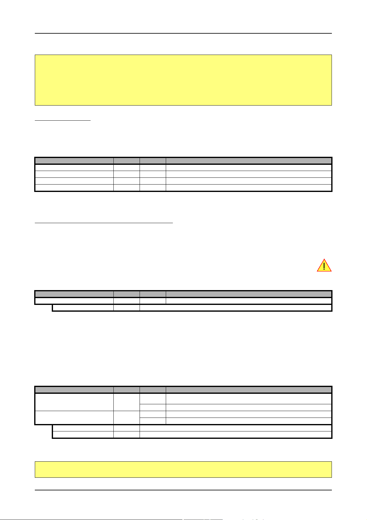
Analog Inputs Setting up the inputs
Please note that this is a general example and the number of input channels may not match the number of channels of your card.
spcm_dwSetParam_i32 (hDrv, SPC_AMP0 , 1000); // Set up channel0 to the range of ± 1.0 V
spcm_dwSetParam_i32 (hDrv, SPC_AMP1 , 1000); // Set up channel1 to the range of ± 1.0 V
spcm_dwSetParam_i32 (hDrv, SPC_AMP2 , 1000); // Set up channel2 to the range of ± 1.0 V
spcm_dwSetParam_i32 (hDrv, SPC_AMP3 , 1000); // Set up channel3 to the range of ± 1.0 V
spcm_dwSetParam_i32 (hDrv, SPC_OFFS0, -100); // Set the input offset to get the signal symmetrically to 0.0 V
spcm_dwSetParam_i32 (hDrv, SPC_OFFS1, -50);
spcm_dwSetParam_i32 (hDrv, SPC_OFFS2, 50);
spcm_dwSetParam_i32 (hDrv, SPC_OFFS3, 100);
Input termination
All inputs of Spectrum’s analog boards can be terminated separately with 50 Ohm by software programming. If you do so, please make sure
that your signal source is able to deliver the higher output currents. If no termination is used, the inputs have an impedance of 1 Megaohm.
The following table shows the corresponding register to set the input termination.
Register Value Direction Description
SPC_50OHM0 30030 read/write A „1“ sets the 50 ohm termination for channel0. A „0“ sets the termination to1 MOhm.
SPC_50OHM1 30130 read/write A „1“ sets the 50 ohm termination for channel1. A „0“ sets the termination to1 MOhm.
SPC_50OHM2 30230 read/write A „1“ sets the 50 ohm termination for channel2. A „0“ sets the termination to1 MOhm.
SPC_50OHM3 30330 read/write A „1“ sets the 50 ohm termination for channel3. A „0“ sets the termination to1 MOhm.
Automatic adjustment of the offset settings
All of the channels are calibrated in factory before the board is shipped. These values are stored in the on-board EEProm under the default
settings. If you have asymmetrical signals, you can adjust the offset easily with the corresponding registers of the inputs as shown before.
To start the automatic offset adjustment, simply write the register, mentioned in the following table.
Before you start an automatic offset adjustment make sure, that no signal is connected to any input. Leave
all the input connectors open and then start the adjustment. All the internal settings of the driver are changed,
while the automatic offset compensation is in progress.
Register Value Direction Description
SPC_ADJ_AUTOADJ 50020 write Performs the automatic offset compensation in the driver either for all input ranges or only the actual.
ADJ_ALL 0 Automatic offset adjustment for all input ranges.
As all settings are temporarily stored in the driver, the automatic adjustment will only affect these values. After exiting your program, all calibration information will be lost. To give you a possibility to save your own settings, most Spectrum card have at least one set of user settings
that can be saved within the on-board EEPROM. The default settings of the offset and gain values are then read-only and cannot be written
to the EEPROM by the user. If the card has no user settings the default settings may be overwritten.
You can easily either save adjustment settings to the EEPROM with SPC_ADJ_SAVE or recall them with SPC_ADJ_LOAD. These two registers
are shown in the table below. The values for these EEPROM access registers are the sets that can be stored within the EEPROM. The amount
of sets available for storing user offset settings depends on the type of board you use. The table below shows all the EEPROM sets, that are
available for your board.
Register Value Direction Description
SPC_ADJ_LOAD 50000 write Loads the specified set of settings from the EEPROM. The default settings are automatically loaded,
read Reads out, what kind of settings have been loaded last.
SPC_ADJ_SAVE 50010 write Stores the actual settings to the specified set in the EEPROM. T
read Reads out, what kind of settings have been saved last.
ADJ_DEFAULT 0 Default settings can be loaded only. These settings cannot be saved by the user.
ADJ_USER0 1 User settings 0. This is a valid set for storing user offset settings to.
If you want to make an offset adjustment on all the channels and store the data to the ADJ_USER0 set of the EEPROM you can do this the
way, the following example shows.
when the driver is started.
spcm_dwSetParam_i32 (hDrv, SPC_ADJ_AUTOADJ, ADJ_ALL ); // Activate offset adjustment on all channels
spcm_dwSetParam_i32 (hDrv, SPC_ADJ_SAVE, ADJ_USER0); // and store values to USER0 set in the EEPROM
(c) Spectrum GmbH 67
Page 68

Setting up the inputs Analog Inputs
If the card has no user settings one can store the values as the default setting like shown here:
spcm_dwSetParam_i32 (hDrv, SPC_ADJ_AUTOADJ, ADJ_ALL ); // Activate offset adjustment on all channels
spcm_dwSetParam_i32 (hDrv, SPC_ADJ_SAVE, ADJ_DEFAULT); // and store values to default set in the EEPROM
When working with a user setting instead of the default ones, you need to restore your user settings with the help of the SPC_ADJ_LOAD
register as the following example shows.
spcm_dwSetParam_i32 (hDrv, SPC_ADJ_LOAD, ADJ_USER0); // and load values to USER0 set in the EEPROM
Read out of input features
The analog inputs of the different cards do have different features implemented, that can be read out to make the software more general. If
you only operate one single card type in your software it is not necessary to read out these features.
Please note that the following table shows all input features settings that are available throughout all Spectrum acquisition cards. Some of
these features are not installed on your specific hardware.
Register Value Direction Description
SPC_READAIFEATURES 3101 read Returns a bit map with the available features of the analog input path. The possible return values are
SPCM_AI_TERM 00000001h Programmable input termination available
SPCM_AI_SE 00000002h Input is single-ended. If available together with SPC_AI_DIFF or SPCM_AI_DIFFMUX: input type is software selectable.
SPCM_AI_DIFF 00000004h Input is differential. If available together with SPC_AI_SE: input type is software selectable and switching from single-
SPCM_AI_OFFSPERCENT 00000008h Input offset programmable in per cent of input range
SPCM_AI_OFFSMV 00000010h Input offset programmable in mV
SPCM_AI_OVERRANGEDETECT 00000020h Programmable overrange detection available
SPCM_AI_DCCOUPLING 00000040h Input is DC coupled. If available together with AC coupling: coupling is software selectable
SPCM_AI_ACCOUPLING 00000080h Input is AC coupled. If available together with DC coupling: coupling is software selectable
SPCM_AI_LOWPASS 00000100h Input has a selectable low pass filter (bandwidth limit)
SPCM_AI_DIFFMUX 00000400h Input is differential. If available together with SPC_AI_SE: input type is software selectable and switching from single-
SPCM_AI_AUTOCALOFFS 00001000h Input offset can be auto calibrated on the card
SPCM_AI_AUTOCALGAIN 00002000h Input gain can be auto calibrated on the card
SPCM_AI_AUTOCALOFFSNOIN 00004000h Input offset can auto calibrated on the card if inputs are left open
SPCM_AI_INDIVPULSEWIDTH 00010000h Trigger pulsewidth is individually per channel programmable
ended to differential does not reduce the number of active channels by combining two single-ended channels.
ended to differential does reduce the number of active channels due to combining two single-ended channels.
listed below.
68 M2i.30xx / M2i.30xx-exp Manual
Page 69

Acquisition modes Overview
Acquisition modes
Your card is able to run in different modes. Depending on the selected mode there are different registers that each define an aspect of this
mode. The single modes are explained in this chapter. Any further modes that are only available if an option is installed on the card is documented in a later chapter.
Overview
This chapter gives you a general overview on the related registers for the different modes. The use of these registers throughout the different
modes is described in the following chapters.
Setup of the mode
The mode register is organized as a bitmap. Each mode corresponds to one bit of this bitmap. When defining the mode to use, please be
sure just to set one of the bits. All other settings will return an error code.
The main difference between all standard and all FIFO modes is that the standard modes are limited to on-board memory and therefore can
run with full sampling rate. The FIFO modes are designed to transfer data continuously over the bus to PC memory or to hard disk and can
therefore run much longer. The FIFO modes are limited by the maximum bus transfer speed the PC can use. The FIFO mode uses the complete
installed on-board memory as a FIFO buffer.
However as you’ll see throughout the detailed documentation of the modes the standard and the FIFO mode are similar in programming and
behavior and there are only a very few differences between them.
Register Value Direction Description
SPC_CARDMODE 9500 read/write Defines the used operating mode, a read command will return the currently used mode.
SPC_AVAILCARDMODES 9501 read Returns a bitmap with all available modes on your card. The modes are listed below.
Acquisition modes
Mode Value Description
SPC_REC_STD_SINGLE 1h Data acquisition to on-board memory for one single trigger event.
SPC_REC_STD_MULTI 2h Data acquisition to on-board memory for multiple trigger events. Each recorded segment has the same size. This mode is described in greater
SPC_REC_STD_GATE 4h Data acquisition to on-board memory using an external Gate signal. Acquisition is only done as long as the gate signal has a programmed
SPC_REC_STD_ABA 8h Data acquisition to on-board memory for multiple trigger events. While the multiple trigger events are stored with programmed sampling rate
SPC_REC_FIFO_SINGLE 10h Continuous data acquisition for one single trigger event. The on-board memory is used completely as FIFO buffer.
SPC_REC_FIFO_MULTI 20h Continuous data acquisition for multiple trigger events.
SPC_REC_FIFO_GATE 40h Continuous data acquisition using an external gate signal.
SPC_REC_FIFO_ABA 80h Continuous data acquisition for multiple trigger events together with continuous data acquisition with a slower sampling clock.
detail in a special chapter about the Multiple Recording option.
level. The mode is described in greater detail in a special chapter about the Gated Sampling option.
the inputs are sampled continuously with a slower sampling speed. The mode is described in a special chapter about ABA mode option.
(c) Spectrum GmbH 69
Page 70

Commands Acquisition modes
Commands
The data acquisition/data replay is controlled by the command register. The command register controls the state of the card in general and
also the state of the different data transfers. Data transfers are explained in an extra chapter later on.
The commands are split up into two types of commands: execution commands that fulfill a job and wait commands that will wait for the
occurrence of an interrupt. Again the commands register is organized as a bitmap allowing you to set several commands together with one
call. As not all of the command combinations make sense (like the combination of reset and start at the same time) the driver will check the
given command and return an error code ERR_SEQUENCE if one of the given commands is not allowed in the current state.
Register Value Direction Description
SPC_M2CMD 100 write only Executes a command for the card or data transfer.
Card execution commands
M2CMD_CARD_RESET 1h Performs a hard and software reset of the card as explained further above.
M2CMD_CARD_WRITESETUP 2h Writes the current setup to the card without starting the hardware. This command may be useful if changing some
M2CMD_CARD_START 4h Starts the card with all selected settings. This command automatically writes all settings to the card if any of the set-
M2CMD_CARD_ENABLETRIGGER 8h The trigger detection is enabled. This command can be either sent together with the start command to enable trigger
M2CMD_CARD_FORCETRIGGER 10h This command forces a trigger even if none has been detected so far. Sending this command together with the start
M2CMD_CARD_DISABLETRIGGER 20h The trigger detection is disabled. All further trigger events are ignored until the trigger detection is again enabled.
M2CMD_CARD_STOP 40h Stops the current run of the card. If the card is not running this command has no effect.
internal settings like clock frequency and enabling outputs.
tings has been changed since the last one was written. After card has been started none of the settings can be
changed while the card is running.
immediately or in a second call after some external hardware has been started.
command is similar to using the software trigger.
When starting the card the trigger detection is started disabled.
Card wait commands
These commands do not return until either the defined state has been reached which is signaled by an interrupt from the card or the timeout
counter has expired. If the state has been reached the command returns with an ERR_OK. If a timeout occurs the command returns with
ERR_TIMEOUT. If the card has been stopped from a second thread with a stop or reset command, the wait function returns with ERR_ABORT.
M2CMD_CARD_WAITPREFULL 1000h Acquisition modes only: the command waits until the pretrigger area has once been filled with data. After pretrigger
M2CMD_CARD_WAITTRIGGER 2000h Waits until the first trigger event has been detected by the card. If using a mode with multiple trigger events like Multi-
M2CMD_CARD_WAITREADY 4000h Waits until the card has completed the current run. In an acquisition mode receiving this command means that all data
area has been filled the internal trigger engine starts to look for trigger events if the trigger detection has been
enabled.
ple Recording or Gated Sampling there only the first trigger detection will generate an interrupt for this wait command.
has been acquired. In a generation mode receiving this command means that the output has stopped.
Wait command timeout
If the state for which one of the wait commands is waiting isn’t reached any of the wait commands will either wait forever if no timeout is
defined or it will return automatically with an ERR_TIMEOUT if the specified timeout has expired.
Register Value Direction Description
SPC_TIMEOUT 295130 read/write Defines the timeout for any following wait command in a millisecond resolution. Writing a zero to this
register disables the timeout.
As a default the timeout is disabled. After defining a timeout this is valid for all following wait commands until the timeout is disabled again
by writing a zero to this register.
A timeout occurring should not be considered as an error. It did not change anything on the board status. The board is still running and will
complete normally. You may use the timeout to abort the run after a certain time if no trigger has occurred. In that case a stop command is
necessary after receiving the timeout. It is also possible to use the timeout to update the user interface frequently and simply call the wait
function afterwards again.
70 M2i.30xx / M2i.30xx-exp Manual
Page 71

Acquisition modes Commands
Example for card control:
// card is started and trigger detection is enabled immediately
spcm_dwSetParam_i32 (hDrv, SPC_M2CMD, M2CMD_CARD_START | M2CMD_CARD_ENABLETRIGGER);
// we wait a maximum of 1 second for a trigger detection. In case of timeout we force the trigger
spcm_dwSetParam_i32 (hDrv, SPC_TIMEOUT, 1000);
if (spcm_dwSetParam_i32 (hDrv, SPC_M2CMD, M2CMD_CARD_WAITTRIGGER) == ERR_TIMEOUT)
{
printf (“No trigger detected so far, we force a trigger now!\n”);
spcm_dwSetParam (hdrv, SPC_M2CMD, M2CMD_CARD_FORCETRIGGER);
}
// we disable the timeout and wait for the end of the run
spcm_dwSetParam_i32 (hDrv, SPC_TIMEOUT, 0);
spcm_dwSetParam_i32 (hDrv, SPC_M2CMD, M2CMD_CARD_WAITREADY);
printf (“Card has stopped now!\n”);
Card Status
In addition to the wait for an interrupt mechanism or completely instead of it one may also read out the current card status by reading the
SPC_M2STATUS register. The status register is organized as a bitmap showing the status of the card and also of the different data transfers.
Register Value Direction Description
SPC_M2STATUS 110 read only Reads out the current status information
M2STAT_CARD_PRETRIGGER 1h Acquisition modes only: the pretrigger area has been filled.
M2STAT_CARD_TRIGGER 2h The first trigger has been detected.
M2STAT_CARD_READY 4h The card has finished its run and is ready.
M2STAT_CARD_SEGMENT_PRETRG 8h Multi/ABA/Gated acquisition of M4i/M4x/M2p only: the pretrigger area of one segment has been filled.
Acquisition cards status overview
The following drawing gives you an overview of the card commands and card status information. After start of card with
M2CMD_CARD_START the card is acquiring pretrigger data until one time complete pretrigger data has been acquired. Then the status
M2STAT_CARD_PRETRIGGER is set. Either the trigger has been enabled together with the start command or the card now waits for trigger
enable command M2CMD_CARD_ENABLETRIGGER. After receiving this command the trigger engine is enabled and card checks for a trigger event. As soon as the trigger event is received the status changes to M2STAT_CARD_TRIGGER and the card acquires the programmed
posttrigger data. After all post trigger data has been acquired the status changes to M2STAT_CARD_READY and data can be read out:
Generation card status overview
This drawing gives an overview of the card commands and status information for a simple generation mode. After start of card with the
M2CMD_CARD_START the card is armed and waiting. Either the trigger has been enabled together with the start command or the card now
waits for trigger enable command M2CMD_CARD_ENABLETRIGGER. After receiving this command the trigger engine is enabled and card
checks for a trigger event. As soon as the trigger event is received the status changes to M2STAT_CARD_TRIGGER and the card starts with
the data replay. After replay has been finished - depending on the programmed mode - the status changes to M2STAT_CARD_READY and
the card stops.
(c) Spectrum GmbH 71
Page 72

Commands Acquisition modes
Data Transfer
Data transfer consists of two parts: the buffer definition and the commands/status information that controls the transfer itself. Data transfer
shares the command and status register with the card control commands and status information. In general the following details on the data
transfer are valid for any data transfer in any direction:
• The memory size register (SPC_MEMSIZE) must be programmed before starting the data transfer.
• Before starting a data transfer the buffer must be defined using the spcm_dwDefTransfer function.
• Each defined buffer is only used once. After transfer has ended the buffer is automatically invalidated.
• If a buffer has to be deleted although the data transfer is in progress or the buffer has at least been defined it is necessary to call the
spcm_dwInvalidateBuf function.
Definition of the transfer buffer
Before any data transfer can start it is necessary to define the transfer buffer with all its details. The definition of the buffer is done with the
spcm_dwDefTransfer function as explained in an earlier chapter.
uint32 _stdcall spcm_dwDefTransfer_i64 (// Defines the transfer buffer by using 64 bit unsigned integer values
drv_handle hDevice, // handle to an already opened device
uint32 dwBufType, // type of the buffer to define as listed below under SPCM_BUF_XXXX
uint32 dwDirection, // the transfer direction as defined below
uint32 dwNotifySize, // number of bytes after which an event is sent (0=end of transfer)
void* pvDataBuffer, // pointer to the data buffer
uint64 qwBrdOffs, // offset for transfer in board memory
uint64 qwTransferLen); // buffer length
This function is used to define buffers for standard sample data transfer as well as for extra data transfer for additional ABA or timestamp
information. Therefore the dwBufType
parameter can be one of the following:
SPCM_BUF_DATA 1000 Buffer is used for transfer of standard sample data
SPCM_BUF_ABA 2000 Buffer is used to read out slow ABA data. Details on this mode are described in the chapter about the ABA mode
SPCM_BUF_TIMESTAMP 3000 Buffer is used to read out timestamp information. Details on this mode are described in the chapter about the
The dwDirection
SPCM_DIR_PCTOCARD 0 Transfer is done from PC memory to on-board memory of card
SPCM_DIR_CARDTOPC 1 Transfer is done from card on-board memory to PC memory.
SPCM_DIR_CARDTOGPU 2 RDMA transfer from card memory to GPU memory, SCAPP option needed, Linux only
SPCM_DIR_GPUTOCARD 3 RDMA transfer from GPU memory to card memory, SCAPP option needed, Linux only
parameter defines the direction of the following data transfer:
option
timestamp option.
The direction information used here must match the currently used mode. While an acquisition mode is used
there’s no transfer from PC to card allowed and vice versa. It is possible to use a special memory test mode
to come beyond this limit. Set the SPC_MEMTEST register as defined further below.
The dwNotifySize
parameter defines the amount of bytes after which an interrupt should be generated. If leaving this parameter zero, the
transfer will run until all data is transferred and then generate an interrupt. Filling in notify size > zero will allow you to use the amount of
data that has been transferred so far. The notify size is used on FIFO mode to implement a buffer handshake with the driver or when transferring large amount of data where it may be of interest to start data processing while data transfer is still running. Please see the chapter on
handling positions further below for details.
The Notify size sticks to the page size which is defined by the PC hardware and the operating system. Therefore the notify size must be a multiple of 4 kByte. For data transfer it may also be a fraction of 4k in the
range of 16, 32, 64, 128, 256, 512, 1k or 2k. No other values are allowed. For ABA and timestamp the notify
size can be 2k as a minimum. If you need to work with ABA or timestamp data in smaller chunks please use the
polling mode as described later.
The pvDataBuffer
must point to an allocated data buffer for the transfer. Please be sure to have at least the amount of memory allocated that
you program to be transferred. If the transfer is going from card to PC this data is overwritten with the current content of the card on-board
memory.
When not doing FIFO mode one can also use the qwBrdOffs
parameter. This parameter defines the starting position for the data transfer as
byte value in relation to the beginning of the card memory. Using this parameter allows it to split up data transfer in smaller chunks if one
has acquired a very large on-board memory.
The qwTransferLen
parameter defines the number of bytes that has to be transferred with this buffer. Please be sure that the allocated memory
has at least the size that is defined in this parameter. In standard mode this parameter cannot be larger than the amount of data defined with
memory size.
72 M2i.30xx / M2i.30xx-exp Manual
Page 73

Acquisition modes Commands
Memory test mode
In some cases it might be of interest to transfer data in the opposite direction. Therefore a special memory test mode is available which allows
random read and write access of the complete on-board memory. While memory test mode is activated no normal card commands are processed:
Register Value Direction Description
SPC_MEMTEST 200700 read/write Writing a 1 activates the memory test mode, no commands are then processed.
Writing a 0 deactivates the memory test mode again.
Invalidation of the transfer buffer
The command can be used to invalidate an already defined buffer if the buffer is about to be deleted by user. This function is automatically
called if a new buffer is defined or if the transfer of a buffer has completed
uint32 _stdcall spcm_dwInvalidateBuf ( // invalidate the transfer buffer
drv_handle hDevice, // handle to an already opened device
uint32 dwBufType); // type of the buffer to invalidate as listed above under SPCM_BUF_XXXX
The dwBufType
parameter need to be the same parameter for which the buffer has been defined:
SPCM_BUF_DATA 1000 Buffer is used for transfer of standard sample data
SPCM_BUF_ABA 2000 Buffer is used to read out slow ABA data. Details on this mode are described in the chapter about the ABA mode
SPCM_BUF_TIMESTAMP 3000 Buffer is used to read out timestamp information. Details on this mode are described in the chapter about the times-
option. The ABA mode is only available on analog acquisition cards.
tamp option. The timestamp mode is only available on analog or digital acquisition cards.
Commands and Status information for data transfer buffers.
As explained above the data transfer is performed with the same command and status registers like the card control. It is possible to send
commands for card control and data transfer at the same time as shown in the examples further below.
Register Value Direction Description
SPC_M2CMD 100 write only Executes a command for the card or data transfer
M2CMD_DATA_STARTDMA 10000h Starts the DMA transfer for an already defined buffer. In acquisition mode it may be that the card hasn’t received a
M2CMD_DATA_WAITDMA 20000h Waits until the data transfer has ended or until at least the amount of bytes defined by notify size are available. This
M2CMD_DATA_STOPDMA 40000h Stops a running DMA transfer. Data is invalid afterwards.
trigger yet, in that case the transfer start is delayed until the card receives the trigger event
wait function also takes the timeout parameter described above into account.
The data transfer can generate one of the following status information:
Register Value Direction Description
SPC_M2STATUS 110 read only Reads out the current status information
M2STAT_DATA_BLOCKREADY 100h The next data block as defined in the notify size is available. It is at least the amount of data available but it also can
M2STAT_DATA_END 200h The data transfer has completed. This status information will only occur if the notify size is set to zero.
M2STAT_DATA_OVERRUN 400h The data transfer had on overrun (acquisition) or underrun (replay) while doing FIFO transfer.
M2STAT_DATA_ERROR 800h An internal error occurred while doing data transfer.
be more data.
Example of data transfer
void* pvData = (void*) new int8[1024];
// transfer data from PC memory to card memory (on replay cards) ...
spcm_dwDefTransfer_i64 (hDrv, SPCM_BUF_DATA, SPCM_DIR_PCTOCARD , 0, pvData, 0, 1024);
spcm_dwSetParam_i32 (hDrv, SPC_M2CMD, M2CMD_DATA_STARTDMA | M2CMD_DATA_WAITDMA);
// ... or transfer data from card memory to PC memory (acquisition cards)
spcm_dwDefTransfer_i64 (hDrv, SPCM_BUF_DATA, SPCM_DIR_CARDTOPC , 0, pvData, 0, 1024);
spcm_dwSetParam_i32 (hDrv, SPC_M2CMD, M2CMD_DATA_STARTDMA | M2CMD_DATA_WAITDMA);
// explicitely stop DMA tranfer prior to invalidating buffer
spcm_dwSetParam_i32 (hDrv, SPC_M2CMD, M2CMD_DATA_STOPDMA);
spcm_dwInvalidateBuf (hDrv, SPCM_BUF_DATA);
delete [] (int8*) pvData;
To keep the example simple it does no error checking. Please be sure to check for errors if using these command in real world programs!
Users should take care to explicitly send the M2CMD_DATA_STOPDMA command prior to invalidating the
buffer, to avoid crashes due to race conditions when using higher-latency data transportation layers, such
as to remote Ethernet devices.
(c) Spectrum GmbH 73
Page 74

Standard Single acquisition mode Acquisition modes
Standard Single acquisition mode
The standard single mode is the easiest and mostly used mode to acquire analog data with a Spectrum acquisition card. In standard single
recording mode the card is working totally independent from the PC, after the card setup is done. The advantage of the Spectrum boards is
that regardless to the system usage the card will sample with equidistant time intervals.
The sampled and converted data is stored in the on-board memory and is held there for being read out after the acquisition. This mode allows
sampling at very high conversion rates without the need to transfer the data into the memory of the host system at high speed.
After the recording is done, the data can be read out by the user and is transferred via the bus into PC memory.
This standard recording mode is the most common mode for all analog and digital acquisition and oscilloscope boards. The data is
written to a programmed amount of the on-board memory (memsize). That part of memory is used as a ring buffer, and recording
is done continuously until a trigger event is detected. After the trigger event, a certain programmable amount of data is recorded
(post trigger) and then the recording finishes. Due to the continuous
ring buffer recording, there are also samples prior to the trigger
event in the memory (pretrigger).
When the card is started the pre trigger area is filled up with data first. While doing this the board’s trigger
detection is not armed. If you use a huge pre trigger size and a slow sample rate it can take some time after
starting the board before a trigger event will be detected.
Card mode
The card mode has to be set to the correct mode SPC_REC_STD_SINGLE.
Register Value Direction Description
SPC_CARDMODE 9500 read/write Defines the used operating mode, a read command will return the currently used mode.
SPC_REC_STD_SINGLE 1h Data acquisition to on-board memory for one single trigger event.
Memory, Pre- and Posttrigger
At first you have to define, how many samples are to be recorded at all and how many of them should be acquired after the trigger event
has been detected.
Register Value Direction Description
SPC_MEMSIZE 10000 read/write Sets the memory size in samples per channel.
SPC_POSTTRIGGER 10100 read/write Sets the number of samples to be recorded per channel after the trigger event has been detected.
You can access these settings by the register SPC_MEMSIZE, which sets the total amount of data that is recorded, and the register
SPC_POSTTRIGGER, that defines the number of samples to be recorded after the trigger event has been detected. The size of the pretrigger
results on the simple formula:
pretrigger = memsize - posttrigger
The maximum memsize that can be use for recording is of course limited by the installed amount of memory and by the number of channels
to be recorded. Please have a look at the topic "Limits of pre, post memsize, loops" later in this chapter.
Example
The following example shows a simple standard single mode data acquisition setup with the read out of data afterwards. To keep this example
simple there is no error checking implemented.
int32 lMemsize = 16384; // recording length is set to 16 kSamples
spcm_dwSetParam_i32 (hDrv, SPC_CHENABLE, CHANNEL0); // only one channel activated
spcm_dwSetParam_i32 (hDrv, SPC_CARDMODE, SPC_REC_STD_SINGLE); // set the standard single recording mode
spcm_dwSetParam_i32 (hDrv, SPC_MEMSIZE, lMemsize); // recording length
spcm_dwSetParam_i32 (hDrv, SPC_POSTTRIGGER, 8192); // samples to acquire after trigger = 8k
// now we start the acquisition and wait for the interrupt that signalizes the end
spcm_dwSetParam_i32 (hDrv, SPC_M2CMD, M2CMD_CARD_START | M2CMD_CARD_ENABLETRIGGER | M2CMD_CARD_WAITREADY);
void* pvData = new int16[lMemsize];
// read out the data
spcm_dwDefTransfer_i64 (hDrv, SPCM_BUF_DATA, SPCM_DIR_CARDTOPC , 0, pvData, 0, 2 * lMemsize);
spcm_dwSetParam_i32 (hDrv, SPC_M2CMD, M2CMD_DATA_STARTDMA | M2CMD_DATA_WAITDMA);
74 M2i.30xx / M2i.30xx-exp Manual
Page 75

Acquisition modes FIFO Single acquisition mode
FIFO Single acquisition mode
The FIFO single mode does a continuous data acquisition using the on-board memory as a FIFO buffer and transferring data continuously to
PC memory. One can make on-line calculations with the acquired data, store the data continuously to disk for later use or even have a data
logger functionality with on-line data display.
Card mode
The card mode has to be set to the correct mode SPC_REC_FIFO_SINGLE.
Register Value Direction Description
SPC_CARDMODE 9500 read/write Defines the used operating mode, a read command will return the currently used mode.
SPC_REC_FIFO_SINGLE 10h Continuous data acquisition to PC memory. Complete on-board memory is used as FIFO buffer.
Length and Pretrigger
Even in FIFO mode it is possible to program a pretrigger area. In general FIFO mode can run forever until it is stopped by an explicit user
command or one can program the total length of the transfer by two counters Loop and Segment size
Register Value Direction Description
SPC_PRETRIGGER 10030 read/write Programs the number of samples to be acquired before the trigger event detection
SPC_SEGMENTSIZE 10010 read/write Length of segments to acquire.
SPC_LOOPS 10020 read/write Number of segments to acquire in total. If set to zero the FIFO mode will run continuously until it is
stopped by the user.
The total amount of samples per channel that is acquired can be calculated by [SPC_LOOPS * SPC_SEGMENTSIZE]. Please stick to the below
mentioned limitations of the registers.
Difference to standard single acquisition mode
The standard modes and the FIFO modes differ not very much from the programming side. In fact one can even use the FIFO mode to get the
same behavior like the standard mode. The buffer handling that is shown in the next chapter is the same for both modes.
Pretrigger
When doing standard single acquisition memory is used as a circular buffer and the pre trigger can be up to the [installed memory] - [minimum
post trigger]. Compared to this the pre trigger in FIFO mode is limited by a special pre trigger FIFO and hence considerably shorter.
Length of acquisition.
In standard mode the acquisition length is defined before the start and is limited to the installed on-board memory whilst in FIFO mode the
acquisition length can either be defined or it can run continuously until user stops it.
Example FIFO acquisition
The following example shows a simple FIFO single mode data acquisition setup with the read out of data afterwards. To keep this example
simple there is no error checking implemented.
spcm_dwSetParam_i32 (hDrv, SPC_CHENABLE, CHANNEL0); // only one channel activated
spcm_dwSetParam_i32 (hDrv, SPC_CARDMODE, SPC_REC_FIFO_SINGLE); // set the FIFO single recording mode
spcm_dwSetParam_i32 (hDrv, SPC_PRETRIGGER, 1024); // 1 kSample of data before trigger
// in FIFO mode we need to define the buffer before starting the transfer
int16* pnData = new int16[lBufsizeInSamples];
spcm_dwDefTransfer_i64 (hDrv, SPCM_BUF_DATA, SPCM_DIR_CARDTOPC, 4096, (void*) pnData, 0, 2 * lBufsizeInSamples);
// now we start the acquisition and wait for the first block
dwError = spcm_dwSetParam_i32 (hDrv, SPC_M2CMD, M2CMD_CARD_START | M2CMD_CARD_ENABLETRIGGER);
dwError = spcm_dwSetParam_i32 (hDrv, SPC_M2CMD, M2CMD_DATA_STARTDMA | M2CMD_DATA_WAITDMA);
// we acquire data in a loop. As we defined a notify size of 4k we’ll get the data in >=4k chuncks
llTotalBytes = 0;
while (!dwError)
{
// read out the available bytes
spcm_dwGetParam_i64 (hDrv, SPC_DATA_AVAIL_USER_LEN, &llAvailBytes);
llTotalBytes += llAvailBytes;
// here is the right position to do something with the data (printf is limited to 32 bit variables)
printf ("Currently Available: %d, total: %d\n", (int32) llAvailBytes, (int32) llTotalBytes);
// now we free the number of bytes and wait for the next buffer
spcm_dwSetParam_i64 (hDrv, SPC_DATA_AVAIL_CARD_LEN, llAvailBytes);
dwError = spcm_dwSetParam_i32 (hDrv, SPC_M2CMD, M2CMD_DATA_WAITDMA);
}
(c) Spectrum GmbH 75
Page 76

Limits of pre trigger, post trigger, memory size Acquisition modes
Limits of pre trigger, post trigger, memory size
The maximum memory size parameter is only limited by the number of activated channels and by the amount of installed memory. Please
keep in mind that each sample needs 2 bytes of memory to be stored. Minimum memory size as well as minimum and maximum post trigger
limits are independent of the activated channels or the installed memory.
Due to the internal organization of the card memory there is a certain stepsize when setting these values that has to be taken into account.
The following table gives you an overview of all limits concerning pre trigger, post trigger, memory size, segment size and loops. The table
shows all values in relation to the installed memory size in samples. If more memory is installed the maximum memory size figures will increase
according to the complete installed memory
Running the card with a sampling rate that is above 100 MS/s switches the cards internally to an interlace mode. In this mode two ADCs
are running in parallel using a 180° shifted signal. Due to the fact that two ADCs are running this mode has a little different limitations and
is listed separately in the following table.
Activated Used Memory size Pre trigger Post trigger Segment size Loops
Channels Mode SPC_MEMSIZE SPC_PRETRIGGER SPC_POSTTRIGGER SPC_SEGMENTSIZE SPC_LOOPS
1 channel Standard Single 8 Mem 4 defined by post trigger 4 8G - 4 4 not used not used
Standard Multi/ABA 8 Mem 4 4 8k - 16 4 4 Mem/2-4 4 8 Mem/2 4 not used
Standard Gate 8 Mem 4 4 8k - 16 4 4 Mem-4 4 not used not used
FIFO Single not used 4 8k - 16 4 not used 8 8G - 4 4 0 (∞)4G - 1 1
FIFO Multi/ABA not used 48k - 16448G - 448Mem/240 (∞)4G - 1 1
FIFO Gate not used 4 8k - 16 4 4 8G - 4 4 not used 0 (∞)4G - 1 1
Interlace Standard Single 16 Mem 8 defined by post trigger 8 8G - 4 8 not used not used
Standard Multi/ABA 16 Mem 8 8 8k - 16 8 8 Mem/2-4 8 16 Mem/2 8 not used
Standard Gate 16 Mem 8 8 8k - 16 8 8 Mem-4 8 not used not used
FIFO Single not used 8 8k - 16 8 not used 16 8G - 4 8 0 (∞)4G - 1 1
FIFO Multi/ABA not used 8 8k - 16 8 8 8G - 4 8 16 Mem/2 8 0 (∞)4G - 1 1
FIFO Gate not used 8 8k - 16 8 8 8G - 4 8 not used 0 (∞)4G - 1 1
2 channels Standard Single 8 Mem/2 4 defined by post trigger 4 8G - 4 4 not used not used
Standard Multi/ABA 8 Mem/2 4 4 4k - 8 4 4 Mem/4-4 4 8 Mem/4 4 not used
Standard Gate 8 Mem/2 4 4 4k - 8 4 4 Mem/2-4 4 not used not used
FIFO Single not used 4 4k - 8 4 not used 8 8G - 4 4 0 (∞)4G - 1 1
FIFO Multi/ABA not used 44k - 8448G - 448Mem/440 (∞)4G - 1 1
FIFO Gate not used 4 4k - 8 4 4 8G - 4 4 not used 0 (∞)4G - 1 1
4 channels Standard Single 8 Mem/4 4 defined by post trigger 4 8G - 4 4 not used not used
Standard Multi/ABA 8 Mem/4 4 4 2k - 4 4 4 Mem/8-4 4 8 Mem/8 4 not used
Standard Gate 8 Mem/4 4 4 2k - 4 4 4 Mem/4-4 4 not used not used
FIFO Single not used 4 2k - 4 4 not used 8 8G - 4 4 0 (∞)4G - 1 1
FIFO Multi/ABA not used 42k - 4448G - 448Mem/840 (∞)4G - 1 1
FIFO Gate not used 4 2k - 4 4 4 8G - 4 4 not used 0 (∞)4G - 1 1
Min Max Step Min Max Step Min Max Step Min Max Step Min Max Step
All figures listed here are given in samples. An entry of [8k - 16] means [8 kSamples - 16] = [8192 - 16] = 8176 samples.
The given memory and memory / divider figures depend on the installed on-board memory as listed below:
Mem 32 MSample 64 MSample 128 MSample 256 MSample 512 MSample 1 GSample 2 GSample
32 MSample 64 MSample 128 MSample 256 MSample 512 MSample 1 GSample 2 GSample
Mem / 2 16 MSample 32 MSample 64 MSample 128 MSample 256 MSample 512 MSample 1 GSample
Mem / 4 8 MSample 16 MSample 32 MSample 64 MSample 128 MSample 256 MSample 512 MSample
Mem / 8 4 MSample 8 MSample 16 MSample 32 MSample 64 MSample 128 MSample 256 MSample
Installed Memory
Please keep in mind that this table shows all values at once. Only the absolute maximum and minimum values are shown. There might be
additional limitations. Which of these values is programmed depends on the used mode. Please read the detailed documentation of the mode.
76 M2i.30xx / M2i.30xx-exp Manual
Page 77

Acquisition modes Buffer handling
Buffer handling
To handle the huge amount of data that can possibly be acquired with the M2i/M3i series cards, there is a very reliable two step buffer
strategy set up. The on-board memory of the card can be completely used as a real FIFO buffer. In addition a part of the PC memory can be
used as an additional software buffer. Transfer between hardware FIFO and software buffer is performed interrupt driven and automatically
by the driver to get best performance. The following drawing will give you an overview of the structure of the data transfer handling:
A data buffer handshake is implemented in the driver which allows to run the card in different data transfer modes. The software transfer
buffer is handled as one large buffer which is on the one side controlled by the driver and filled automatically by busmaster DMA from/to
the hardware FIFO buffer and on the other hand it is handled by the user who set’s parts of this software buffer available for the driver for
further transfer. The handshake is fulfilled with the following 3 software registers:
Register Value Direction Description
SPC_DATA_AVAIL_USER_LEN 200 read Returns the number of currently to the user available bytes inside a sample data transfer.
SPC_DATA_AVAIL_USER_POS 201 read Returns the position as byte index where the currently available data samples start.
SPC_DATA_AVAIL_CARD_LEN 202 write Writes the number of bytes that the card can now use for sample data transfer again
Internally the card handles two counters, a user counter and a card counter. Depending on the transfer direction the software registers have
slightly different meanings:
Transfer direction Register Direction Description
Write to card SPC_DATA_AVAIL_USER_LEN read This register contains the currently available number of bytes that are free to write new data to the
SPC_DATA_AVAIL_CARD_LEN write After filling an amount of the buffer with new data to transfer to card, the user tells the driver with this
Read from card SPC_DATA_AVAIL_USER_LEN read This register contains the currently available number of bytes that are filled with newly transferred
SPC_DATA_AVAIL_CARD_LEN write After finishing the job with the new available data the user needs to tell the driver that this amount of
Any direction SPC_DATA_AVAIL_USER_POS read The register holds the current byte index position where the available bytes start. The register is just
Any direction SPC_FILLSIZEPROMILLE read The register holds the current fill size of the on-board memory (FIFO buffer) in promille (1/1000) of
card. The user can now fill this amount of bytes with new data to be transferred.
register that the amount of data is now ready to transfer.
data. The user can now use this data for own purposes, copy it, write it to disk or start calculations
with this data.
bytes is again free for new data to be transferred.
intended to help you and to avoid own position calculation
the full on-board memory. Please note that the hardware reports the fill size only in 1/16 parts of the
full memory. The reported fill size is therefore only shown in 1000/16 = 63 promille steps.
Directly after start of transfer the SPC_DATA_AVAIL_USER_LEN is every time zero as no data is available for the user and the
SPC_DATA_AVAIL_CARD_LEN is every time identical to the length of the defined buffer as the complete buffer is available for the card for
transfer.
The counter that is holding the user buffer available bytes (SPC_DATA_AVAIL_USER_LEN) is sticking to the defined notify size at the DefTransfer call. Even when less bytes already have been transferred you won’t get
notice of it if the notify size is programmed to a higher value.
Remarks
• The transfer between hardware FIFO buffer and application buffer is done with scatter-gather DMA using a busmaster DMA controller
located on the card. Even if the PC is busy with other jobs data is still transferred until the application data buffer is completely used.
• Even if application data buffer is completely used there’s still the hardware FIFO buffer that can hold data until the complete on-board
memory is used. Therefore a larger on-board memory will make the transfer more reliable against any PC dead times.
• As you see in the above picture data is directly transferred between application data buffer and on-board memory. Therefore it is abso-
lutely critical to delete the application data buffer without stopping any DMA transfers that are running actually. It is also absolutely critical to define the application data buffer with an unmatching length as DMA can than try to access memory outside the application data
(c) Spectrum GmbH 77
Page 78

Buffer handling Acquisition modes
area.
• As shown in the drawing above the DMA control will announce new data to the application by sending an event. Waiting for an event is
done internally inside the driver if the application calls one of the wait functions. Waiting for an event does not consume any CPU time
and is therefore highly desirable if other threads do a lot of calculation work. However it is not necessary to use the wait functions and
one can simply request the current status whenever the program has time to do so. When using this polling mode the announced available bytes still stick to the defined notify size!
• If the on-board FIFO buffer has an overrun (card to PC) or an underrun (PC to card) data transfer is stopped. However in case of transfer
from card to PC there is still a lot of data in the on-board memory. Therefore the data transfer will continue until all data has been transferred although the status information already shows an overrun.
• Getting best bus transfer performance is done using a „continuous buffer“. This mode is explained in the appendix in greater detail.
The Notify size sticks to the page size which is defined by the PC hardware and the operating system. Therefore the notify size must be a multiple of 4 kByte. For data transfer it may also be a fraction of 4k in the
range of 16, 32, 64, 128, 256, 512, 1k or 2k. No other values are allowed. For ABA and timestamp the notify
size can be 2k as a minimum. If you need to work with ABA or timestamp data in smaller chunks please use the
polling mode as described later.
The following graphs will show the current buffer positions in different states of the transfer. The drawings have been made for the transfer
from card to PC. However all the block handling is similar for the opposite direction, just the empty and the filled parts of the buffer are
inverted.
Step 1: Buffer definition
Directly after buffer definition the complete buffer is empty (card to PC) or
completely filled (PC to card). In our example we have a notify size which
is 1/4 of complete buffer memory to keep the example simple. In real
world use it is recommended to set the notify size to a smaller stepsize.
Step 2: Start and first data available
In between we have started the transfer and have waited for the first data
to be available for the user. When there is at least one block of notify size
in the memory we get an interrupt and can proceed with the data. Any
data that already was transferred is announced. The USER_POS is still
zero as we are right at the beginning of the complete transfer.
Step 3: set the first data available for card
Now the data can be processed. If transfer is going from card to PC that
may be storing to hard disk or calculation of any figures. If transfer is going from PC to card that means we have to fill the available buffer again
with data. After the amount of data that has been processed by the user
application we set it available for the card and for the next step.
Step 4: next data available
After reaching the next border of the notify size we get the next part of the
data buffer to be available. In our example at the time when reading the
USER_LEN even some more data is already available. The user position
will now be at the position of the previous set CARD_LEN.
Step 5: set data available again
Again after processing the data we set it free for the card use.
In our example we now make something else and don’t react to the interrupt for a longer time. In the background the buffer is filled with more data.
Step 6: roll over the end of buffer
Now nearly the complete buffer is filled. Please keep in mind that our current user position is still at the end of the data part that we processed and
marked in step 4 and step 5. Therefore the data to process now is split in
two parts. Part 1 is at the end of the buffer while part 2 is starting with
address 0.
Step 7: set the rest of the buffer available
Feel free to process the complete data or just the part 1 until the end of
the buffer as we do in this example. If you decide to process complete
buffer please keep in mind the roll over at the end of the buffer.
This buffer handling can now continue endless as long as we manage to
set the data available for the card fast enough. The USER_POS and USER_LEN for step 8 would now look exactly as the buffer shown in step 2.
78 M2i.30xx / M2i.30xx-exp Manual
Page 79

Acquisition modes Buffer handling
Buffer handling example for transfer from card to PC
char* pcData = new char[lBufferSizeInBytes];
// we now define the transfer buffer with the minimum notify size of on page = 4 kByte
spcm_dwDefTransfer_i64 (hDrv, SPCM_BUF_DATA, SPCM_DIR_CARDTOPC , 4096, (void*) pcData, 0, lBufferSizeInBytes);
// we start the DMA transfer
dwError = spcm_dwSetParam_i32 (hDrv, SPC_M2CMD, M2CMD_DATA_STARTDMA);
do
{
if (!dwError)
{
// we wait for the next data to be available. Afte this call we get at least 4k of data to proceed
dwError = spcm_dwSetParam_i32 (hDrv, SPC_M2CMD, M2CMD_DATA_WAITDMA);
// if there was no error we can proceed and read out the available bytes that are free again
spcm_dwGetParam_i32 (hDrv, SPC_DATA_AVAIL_USER_LEN, &lAvailBytes);
spcm_dwGetParam_i32 (hDrv, SPC_DATA_AVAIL_USER_POS, &lBytePos);
printf (“We now have %d new bytes available\n”, lAvailBytes);
printf (“The available data starts at position %d\n”, lBytesPos);
// we take care not to go across the end of the buffer
if ((lBytePos + lAvailBytes) >= lBufferSizeInBytes)
lAvailBytes = lBufferSizeInBytes - lBytePos;
// our do function gets a pointer to the start of the available data section and the length
vDoSomething (&pcData[lBytesPos], lAvailBytes);
// the buffer section is now immediately set available for the card
spcm_dwSetParam_i32 (hDrv, SPC_DATA_AVAIL_CARD_LEN, lAvailBytes);
}
}
while (!dwError); // we loop forever if no error occurs
Buffer handling example for transfer from PC to card
char* pcData = new char[lBufferSizeInBytes];
// before starting transfer we ned to once fill complete buffer memory with data
vDoGenerateData (&pcData[0], lBufferSizeInBytes);
// we now define the transfer buffer with the minimum notify size of on page = 4 kByte
spcm_dwDefTransfer_i64 (hDrv, SPCM_BUF_DATA, SPCM_DIR_PCTOCARD , 4096, (void*) pcData, 0, lBufferSizeInBytes);
// before start we once have to fill some data in for the start of the output
spcm_dwSetParam_i32 (hDrv, SPC_DATA_AVAIL_CARD_LEN, lBufferSizeInBytes);
dwError = spcm_dwSetParam_i32 (hDrv, SPC_M2CMD, M2CMD_DATA_STARTDMA | M2CMD_DATA_WAITDMA);
do
{
if (!dwError)
{
// if there was no error we can proceed and read out the current amount of available data
spcm_dwGetParam_i32 (hDrv, SPC_DATA_AVAIL_USER_LEN, &lAvailBytes);
spcm_dwGetParam_i32 (hDrv, SPC_DATA_AVAIL_USER_POS, &lBytePos);
printf (“We now have %d free bytes available\n”, lAvailBytes);
printf (“The available data starts at position %d\n”, lBytesPos);
// we take care not to go across the end of the buffer
if ((lBytePos + lAvailBytes) >= lBufferSizeInBytes)
lAvailBytes = lBufferSizeInBytes - lBytePos;
// our do function gets a pointer to the start of the available data section and the length
vDoGenerateData (&pcData[lBytesPos], lAvailBytes);
// now we mark the number of bytes that we just generated for replay
// and wait for the next free buffer
spcm_dwSetParam_i32 (hDrv, SPC_DATA_AVAIL_CARD_LEN, lAvailBytes);
dwError = spcm_dwSetParam_i32 (hDrv, SPC_M2CMD, M2CMD_DATA_WAITDMA);
}
}
while (!dwError); // we loop forever if no error occurs
Please keep in mind that you are using a continuous buffer writing/reading that will start again at the zero
position if the buffer length is reached. However the DATA_AVAIL_USER_LEN register will give you the complete amount of available bytes even if one part of the free area is at the end of the buffer and the second
half at the beginning of the buffer.
(c) Spectrum GmbH 79
Page 80

Data organisation Acquisition modes
Data organisation
Data is organized in a multiplexed way in the transfer buffer. If using 4 channels, data of the first activated channel of first module comes
first, then data of first activated channel of second module, then second activated channel of first module and so on.
Activated Channels Ch0 Ch1 Ch2 Ch3 Samples ordering in buffer memory starting with data offset zero
1 channel X A0 A1 A2 A3 A4 A5 A6 A7 A8 A9 A10 A11 A12 A13 A14 A15 A16
1 channel X B0 B1 B2 B3 B4 B5 B6 B7 B8 B9 B10 B11 B12 B13 B14 B15 B16
1 channel X C0 C1 C2 C3 C4 C5 C6 C7 C8 C9 C10 C11 C12 C13 C14 C15 C16
1 channel X D0 D1 D2 D3 D4 D5 D6 D7 D8 D9 D10 D11 D12 D13 D14 D15 D16
2 channels X X A0 B0 A1 B1 A2 B2 A3 B3 A4 B4 A5 B5 A6 B6 A7 B7 A8
2 channels X X A0C0A1C1A2C2A3C3A4C4A5C5A6C6A7C7A8
2 channels X X A0 D0 A1 D1 A2 D2 A3 D3 A4 D4 A5 D5 A6 D6 A7 D7 A8
2 channels X X B0 C0 B1 C1 B2 C2 B3 C3 B4 C4 B5 C5 B6 C6 B7 C7 B8
2 channels X X B0 D0 B1 D1 B2 D2 B3 D3 B4 D4 B5 D5 B6 D6 B7 D7 B8
2 channels X X C0 D0 C1 D1 C2 D2 C3 D3 C4 D4 C5 D5 C6 D6 C7 D7 C8
4 channels X X X X A0 C0 B0 D0 A1 C1 B1 D1 A2 C2 B2 D2 A3 C3 B3 D3 A4
The samples are re-named for better readability. A0 is sample 0 of channel 0, C4 is sample 4 of channel 2, and so on.
Sample format
The 12 bit A/D samples are stored in two’s complement in the lower 12 bit of the 16 bit data word. 12 bit resolution means that data is
ranging from -2048…to…+2047. In standard mode the upper four bits contain the sign extension allowing to directly use the read data as
16 bit integer values. If digital inputs are activated these inputs are stored in the four upper bits. If overrange detection is activated the highest
bit is used to store the overrange information.
Bit Standard Mode Digital inputs (option)
D15 ADx Bit 11 (MSB) Digital bit 3 of channel x Overrange of channel x Overrange of channel x
D14 ADx Bit 11 (MSB) Digital bit 2 of channel x ADx Bit 11 (MSB) Digital bit 2 of channel x
D13 ADx Bit 11 (MSB) Digital bit 1 of channel x ADx Bit 11 (MSB) Digital bit 1 of channel x
D12 ADx Bit 11 (MSB) Digital bit 0 of channel x ADx Bit 11 (MSB) Digital bit 0 of channel x
D11 ADx Bit 11 (MSB) ADx Bit 11 (MSB) ADx Bit 11 (MSB) ADx Bit 11 (MSB)
D10 ADx Bit 10 ADx Bit 10 ADx Bit 10 ADx Bit 10
D9 ADx Bit 9 ADx Bit 9 ADx Bit 9 ADx Bit 9
D8 ADx Bit 8 ADx Bit 8 ADx Bit 8 ADx Bit 8
D7 ADx Bit 7 ADx Bit 7 ADx Bit 7 ADx Bit 7
D6 ADx Bit 6 ADx Bit 6 ADx Bit 6 ADx Bit 6
D5 ADx Bit 5 ADx Bit 5 ADx Bit 5 ADx Bit 5
D4 ADx Bit 4 ADx Bit 4 ADx Bit 4 ADx Bit 4
D3 ADx Bit 3 ADx Bit 3 ADx Bit 3 ADx Bit 3
D2 ADx Bit 2 ADx Bit 2 ADx Bit 2 ADx Bit 2
D1 ADx Bit 1 ADx Bit 1 ADx Bit 1 ADx Bit 1
D0 ADx Bit 0 (LSB) ADx Bit 0 (LSB) ADx Bit 0 (LSB) ADx Bit 0 (LSB)
enabled
Overrange enabled Overrange and digital
inputs (option) enabled
Converting ADC samples to voltage values
The Spectrum driver also contains a register that holds the value of the decimal value of the full scale representation of the installed ADC. This
value should be used when converting ADC values (in LSB) into real-world voltage values, because this register also automatically takes any
specialities into account, such as slightly reduced ADC resolution with reserved codes for gain/offset compensation.
Register Value Direction Description
SPC_MIINST_MAXADCVALUE 1126 read Contains the decimal code (in LSB) of the ADC full scale value.
In case of a board that uses an 8 bit ADC that provides the full ADC code (without reserving any bits) the returned value would be 128. The the peak value for
a ±1.0 V input range would be 1.0 V (or 1000 mv).
A returned sample value of for example +49 (decimal, two’s complement,
signed representation) would then convert to:
A returned sample value of for example -55 (decimal) would then convert to:
When converting samples that contain any additional data such as for example additional digital channels
or overrange bits, this extra information must be first masked out and a proper sign-extension must be per-
formed, before these values can be used as a signed two’s complement value for above formulas.
80 M2i.30xx / M2i.30xx-exp Manual
Vin49
V
in
1000 mV
----------------------------------------------
× 382.81 mV==
128
1000 mV
----------------------------------------------
55–
× 429 .69 mV–==
128
Page 81

Acquisition modes Data organisation
(c) Spectrum GmbH 81
Page 82

Overview Clock generation
Clock generation
Overview
The different clock modes
The Spectrum M2i cards offer a wide variety of different
clock modes to match all the customers needs. All of the
clock modes are described in detail with programming examples in this chapter.
The figure is showing an overview of the complete engine
used on all M2i cards for clock generation.
The purpose of this chapter is to give you a guide to the
best matching clock settings for your specific application
and needs.
Standard internal sample rate (PLL)
PLL with internal 10 MHz reference. This is the easiest and most common way to generate a sample rate with no need for additional external
clock signals. The sample rate has a fine resolution. You can find details on the granularity of the clock in PLL mode in the technical data
section of this manual.
Quartz1 with or without divider
This mode provides an internal sampling quartz clock with a dedicated divider. It’s best suited for applications that need an even lower clock
jitter than the PLL produces. The possible sample rates are restricted to the values of the divider. For details on the available divider values
please see the according section in this chapter or take a look at the technical data section of this manual.
Quartz2 with or without PLL and/or with or without divider (optional)
This optional second Quartz2 is for special customer needs, either for a special direct sampling clock or as a very precise reference for the
PLL. Please feel free to contact Spectrum for your special needs.
External reference clock
PLL with external 1 MHz to 125 MHz reference clock. This provides a very good clock accuracy if a stable external reference clock is used.
It also allows the easy synchronization with an external source.
Direct external clock
Any clock can be fed in that matches the specification of the board. The external clock signal can be used to synchronize the board on a
system clock or to feed in an exact matching sample rate.
Direct external clock is not available for M2i.49xx cards. Please use external reference clock mode instead.
External clock with divider
In addition to the direct external clocking it is also possible to use the externally fed in clock and divide it for generating a low-jitter sample
rate of a slower speed than the external clock available.
Direct external clock with divider is not available for M2i.49xx cards. Please use external reference clock
mode instead.
Synchronization clock (optional)
The star-hub option allows the synchronization of up to 16 cards of the M2i series from Spectrum with a minimal phase delay between the
different cards. As this clock is also available at the dividers input, cards of the same or slower sampling speeds can be synchronized. For
details on the synchronization option please take a look at the dedicated chapter in this manual.
82 M2i.30xx / M2i.30xx-exp Manual
Page 83

Clock generation Internally generated sample rate
Clock Mode Register
The selection of the different clock modes has to be done by the SPC_CLOCKMODE register. All available modes, can be read out by the
help of the SPC_AVAILCLOCKMODES register.
Register Value Direction Description
SPC_AVAILCLOCKMODES 20201 read Bitmask, in which all bits of the below mentioned clock modes are set, if available.
SPC_CLOCKMODE 20200 read/write Defines the used clock mode or reads out the actual selected one.
SPC_CM_INTPLL 1 Enables internal PLL with 10 MHz internal reference for sample clock generation
SPC_CM_QUARTZ1 2 Enables Quartz1 for sample clock generation
SPC_CM_QUARTZ2 4 Enables optional Quartz2 for sample clock generation
SPC_CM_EXTERNAL 8 Enables external clock input for direct sample clock generation
SPC_CM_EXTDIVIDER 16 Enables external clock input for divided sample clock generation
SPC_CM_EXTREFCLOCK 32 Enables internal PLL with external reference for sample clock generation
The different clock modes and all other related or required register settings are described on the following pages.
Internally generated sample rate
Standard internal sampling clock (PLL)
The internal sampling clock is generated in default mode by a PLL and dividers out of an internal precise 10 MHz frequency reference. You
can select the clock mode by the dedicated register shown in the table below:
Register Value Direction Description
SPC_CLOCKMODE 20200 read/write Defines the used clock mode
SPC_CM_INTPLL 1 Enables internal PLL with 10 MHz internal reference for sample clock generation
In most cases the user does not have to care about how the desired sampling rate is generated by multiplying and dividing internally. You
simply write the desired sample rate to the according register shown in the table below and the driver makes all the necessary calculations.
If you want to make sure the sample rate has been set correctly you can also read out the register and the driver will give you back the
sampling rate that is matching your desired one best.
Register Value Direction Description
SPC_SAMPLERATE 20000 write Defines the sample rate in Hz for internal sample rate generation.
read Read out the internal sample rate that is nearest matching to the desired one.
If a sampling rate is generated internally, you can additionally enable the clock output. The clock will be available on the external clock
connector and can be used to synchronize external equipment with the board.
Register Value Direction Description
SPC_CLOCKOUT 20110 read/write Enables clock output on external clock connector.On A/D and D/A cards only possible with internal
SPC_CLOCKOUTFREQUENCY 20111 read Allows to read out the frequency of an internally synthesized clock present at the clock output.
clocking.
Example on writing and reading internal sampling rate
spcm_dwSetParam_i32 (hDrv, SPC_CLOCKMODE, SPC_CM_INTPLL); // Enables internal PLL mode
spcm_dwSetParam_i32 (hDrv, SPC_SAMPLERATE, 1000000); // Set internal sampling rate to 1 MHz
spcm_dwSetParam_i32 (hDrv, SPC_CLOCKOUT, 1); // enable the clock output of that 1 MHz clock
spcm_dwGetParam_i32 (hDrv, SPC_SAMPLERATE, &lSamplerate); // Read back the programmed sample rate and
printf („Sample rate = %d\n“, lSamplerate); // print it. Output should be „Sample rate = 1000000“
Minimum internal sample rate
The minimum internal sample rate on all M2i cards is limited to 1 kHz and the maximum sample rate depends on the specific type of board.
The maximum sample rates for your type of card are shown in the tables below.
(c) Spectrum GmbH 83
Page 84

Internally generated sample rate Clock generation
Maximum internal sampling rate in MS/s
activated Channels
Ch0Ch1Ch2Ch3
M2i.3010
M2i.3011
M2i.3012
M2i.3013
M2i.3014
M2i.3015
M2i.3016
M2i.3020
M2i.3021
M2i.3022
M2i.3023
M2i.3024
M2i.3025
M2i.3026
M2i.3027
M2i.3031
M2i.3033
X 80 40 80 40 80 160 160 105 50 105 50 105 200 200 105 62.5 62.5
X n.a. 40 80 40 80 80 80 n.a. 50 105 50 105 105 105 105 62.5 62.5
X n.a. n.a. n.a. 40 80 n.a. 80 n.a. n.a. n.a. 50 105 n.a. 105 n.a. n.a. 62.5
X X n.a. 40 40 40 40 80 40 n.a. 50 50 50 50 105 50 105 62.5 62.5
X X n.a. n.a. n.a. 40 80 n.a. 80 n.a. n.a. n.a. 50 105 n.a. 105 n.a. n.a. 62.5
X X n.a. n.a. n.a. 40 80 n.a. 80 n.a. n.a. n.a. 50 105 n.a. 105 n.a. n.a. 62.5
X X n.a. n.a. n.a. 40 80 n.a. 80 n.a. n.a. n.a. 50 105 n.a. 105 n.a. n.a. 62.5
X X n.a. n.a. n.a. 40 80 n.a. 80 n.a. n.a. n.a. 50 105 n.a. 105 n.a. n.a. 62.5
X X X X n.a. n.a. n.a. 40 40 n.a. 40 n.a. n.a. n.a. 50 50 n.a. 50 n.a. n.a. 62.5
X n.a. n.a. n.a. 40 80 n.a. 80 n.a. n.a. n.a. 50 105 n.a. 105 n.a. n.a. 62.5
X X n.a. n.a. n.a. 40 40 n.a. 40 n.a. n.a. n.a. 50 50 n.a. 50 n.a. n.a. 62.5
The interlace mode (160/200 MS/s) is only working with a sampling rate programmed exactly to the men-
tioned value of 160 MS/s or 200 MS/s. It is not possible to use the interlace mode with a sampling rate that
is set to anything inbetween Interlace and Interlace/2, for example 140 MS/s!
Using plain Quartz1 without PLL
In some cases it is useful for the application not to have the on-board PLL activated. Although the PLL used on the Spectrum boards is a lowjitter version it still produces more clock jitter than a plain quartz oscillator. For these cases the Spectrum boards have the opportunity to switch
off the PLL by software and use a simple clock divider.
Register Value Direction Description
SPC_CLOCKMODE 20200 read/write Defines the used clock mode
SPC_CM_QUARTZ1 2 Enables Quartz1 for sample clock generation
The Quartz1 used on the board is similar to the maximum sampling rate the board can achieve. As with internal PLL mode it’s also possible
to program the clock mode first, set a desired sampling rate with the SPC_SAMPLERATE register and to read it back. The driver will internally
set the divider and find the closest matching sampling rate. The result will then again be the best matching sampling rate.
If a sampling rate is generated internally, you can additionally enable the clock output. The clock will be available on the external clock
connector and can be used to synchronize external equipment with the board.
Register Value Direction Description
SPC_CLOCKOUT 20110 read/write Enables clock output on external clock connector.On A/D and D/A cards only possible with internal
SPC_CLOCKOUTFREQUENCY 20111 read Allows to read out the frequency of an internally synthesized clock present at the clock output.
clocking.
Using plain Quartz2 without PLL (optional)
In some cases it is necessary to use a special frequency for sampling rate generation. For these applications all cards of the M2i series can
be equipped with a special customer quartz. Please contact Spectrum for details on available oscillators. If your card is equipped with a
second oscillator you can enable it for sampling rate generation with the following register:
Register Value Direction Description
SPC_CLOCKMODE 20200 read/write Defines the used clock mode
SPC_CM_QUARTZ2 4 Enables optional quartz2 for sample clock generation
In addition to the direct usage of the second clock oscillator one can program the internal clock divider to use slower sampling rates. As with
internal PLL mode it’s also possible to program the clock mode first, set a desired sampling rate with the SPC_SAMPLERATE register and to
read it back. The result will then again be the best matching sampling rate.
If a sampling rate is generated internally, you can additionally enable the clock output. The clock will be available on the external clock
connector and can be used to synchronize external equipment with the board.
Register Value Direction Description
SPC_CLOCKOUT 20110 read/write Enables clock output on external clock connector.On A/D and D/A cards only possible with internal
SPC_CLOCKOUTFREQUENCY 20111 read Allows to read out the frequency of an internally synthesized clock present at the clock output.
84 M2i.30xx / M2i.30xx-exp Manual
clocking.
Page 85

Clock generation External reference clock
External reference clock
If you have an external clock generator with a extremely stable frequency, you can use it as a reference clock. You can connect it to the
external clock connector and the PLL will be fed with this clock instead of the internal reference. The following table shows how to enable the
reference clock mode:
Register Value Direction Description
SPC_CLOCKMODE 20200 read/write Defines the used clock mode
SPC_CM_EXTREFCLOCK 32 Enables internal PLL with external reference for sample clock generation
Due to the fact that the driver needs to know the external fed in frequency for an exact calculation of the sampling rate you must set the
SPC_REFERENCECLOCK register accordingly as shown in the table below. The driver automatically then sets the PLL to achieve the desired
sampling rate. Please be aware that the PLL has some internal limits and not all desired sampling rates may be reached with every reference
clock.
Register Value Direction Description
SPC_REFERENCECLOCK 20140 read/write Programs the external reference clock in the range from 1 MHz to 125 MHz.
External sampling rate in Hz as an integer value You need to set up this register exactly to the frequency of the external fed in clock.
Example of reference clock:
spcm_dwSetParam_i32 (hDrv, SPC_CLOCKMODE, SPC_CM_EXTREFCLOCK); // Set to reference clock mode
spcm_dwSetParam_i32 (hDrv, SPC_REFERENCECLOCK, 10000000); // Reference clock that is fed in is 10 MHz
spcm_dwSetParam_i32 (hDrv, SPC_SAMPLERATE, 25000000); // We want to have 25 MHz as sampling rate
The reference clock must be defined via the SPC_REFERENCECLOCK register prior to defining the sample rate
via the SPC_SAMPLERATE register to allow the driver to calculate the proper clock settings correctly.
Termination of the clock input
If the external connector is used as an input, either for feeding in an external reference clock or for external clocking you can enable a
50 Ohm termination on the board. If the termination is disabled, the impedance is high. Please make sure that your source is capable of
driving that current and that it still fulfills the clock input specification as given in the technical data section.
Register Value Direction Description
SPC_CLOCK50OHM 20120 read/write A „1“ enables the 50 Ohm termination at the external clock connector. Only possible, when using
the external connector as an input.
Oversampling
All fast A/D converters have a minimum clock frequency that is defined by the manufacturer of this A/D converter. You find this minimum
sampling rate specified in the technical data section as minimum external sampling clock.
When using one of the above mentioned internal clock modes the driver allows you to program sampling clocks that lie far beneath this
minimum A/D converter clock. To run the A/D converter properly we use a special oversampling mode where the A/D converter is within
its specification and only the digital part of the card is running with the slower clock. This is completely defined inside the driver and cannot
be modified by the user. The following register allows to read out the oversampling factor for further calculation
Register Value Direction Description
SPC_OVERSAMPLINGFACTOR 200123 read only Returns the oversampling factor for further calculations. If oversampling isn’t active a 1 is returned.
The oversampling factor is of interest for three different cases:
• When using clock output the sampling clock at the output connector is the real A/D converter clock and not the programmed slower sam-
pling rate. To calculate the output clock, please just multiply the programmed sampling clock with the oversampling factor read with the
above mentioned register.
• As all modern A/D converters have a data pipeline integrated to obtain high speed sampling together with high resolution there is a
delay between the trigger and the valid data. Our hardware compensates this delay internally as long as sampling is done synchronously. When oversampling is active this compensation no longer works and data is shifted compared to the trigger position by a couple
of samples.
• When using the timestamp option the counter is also running with the real A/D converter clock and not with the programmed slower sam-
pling clock. When interpreting timestamp values it is therefore necessary to check the oversampling factor and take it into account.
(c) Spectrum GmbH 85
Page 86

External clocking Clock generation
External clocking
Direct external clock
An external clock can be fed in on the external clock connector of the board. This can be any clock, that matches the specification of the
card. The external clock signal can be used to synchronize the card on a system clock or to feed in an exact matching sampling rate.
Register Value Direction Description
SPC_CLOCKMODE 20200 read/write Defines the used clock mode
SPC_CM_EXTERNAL 8 Enables external clock input for direct sample clock generation
The maximum values for the external clock is board dependant and shown in the table below.
Termination of the clock input
If the external connector is used as an input, either for feeding in an external reference clock or for external clocking you can enable a
50 Ohm termination on the board. If the termination is disabled, the impedance is high. Please make sure that your source is capable of
driving that current and that it still fulfills the clock input specification as given in the technical data section.
Register Value Direction Description
SPC_CLOCK50OHM 20120 read/write A „1“ enables the 50 Ohm termination at the external clock connector. Only possible, when using
Minimum external sample rate
The minimum external sample rate is limited on all boards to 1 MHz and the maximum sample rate depends on the specific type of board.
The maximum sample rates for your type of board are shown in the tables below.
the external connector as an input.
Maximum external sampling rate in MS/s
activated Channels
Ch0Ch1Ch2Ch3
M2i.3010
M2i.3011
M2i.3012
M2i.3013
M2i.3014
M2i.3015
M2i.3016
M2i.3020
M2i.3021
M2i.3022
M2i.3023
M2i.3024
M2i.3025
M2i.3026
M2i.3027
M2i.3031
X 80 40 80 40 80 80 80 105 50 105 50 105 105 105 105 62.5 62.5
X n.a. 40 80 40 80 80 80 n.a. 50 105 50 105 105 105 105 62.5 62.5
X n.a. n.a. n.a. 40 80 n.a. 80 n.a. n.a. n.a. 50 105 n.a. 105 n.a. n.a. 62.5
X X n.a. 40 40 40 40 80 40 n.a. 50 50 50 50 105 50 105 62.5 62.5
X X n.a. n.a. n.a. 40 80 n.a. 80 n.a. n.a. n.a. 50 105 n.a. 105 n.a. n.a. 62.5
X X n.a. n.a. n.a. 40 80 n.a. 80 n.a. n.a. n.a. 50 105 n.a. 105 n.a. n.a. 62.5
X X n.a. n.a. n.a. 40 80 n.a. 80 n.a. n.a. n.a. 50 105 n.a. 105 n.a. n.a. 62.5
X X n.a. n.a. n.a. 40 80 n.a. 80 n.a. n.a. n.a. 50 105 n.a. 105 n.a. n.a. 62.5
X X X X n.a. n.a. n.a. 40 40 n.a. 40 n.a. n.a. n.a. 50 50 n.a. 50 n.a. n.a. 62.5
X n.a. n.a. n.a. 40 80 n.a. 80 n.a. n.a. n.a. 50 105 n.a. 105 n.a. n.a. 62.5
X X n.a. n.a. n.a. 40 40 n.a. 40 n.a. n.a. n.a. 50 50 n.a. 50 n.a. n.a. 62.5
An external sample rate above the mentioned maximum can cause damage to the board.
The following table shows the available ranges when using external clocking:
Register Value Direction Description
SPC_EXTERNRANGE 20130 read/write Defines the range of the actual fed in external clock. Use one of the below mentioned ranges
EXRANGE_LOW 64 External range for slower clocks
EXRANGE_HIGH 128 External range for faster clocks
The range must not be left by more than 5% when the board is running. Remember that the ranges depend
on the activated channels as well, so a different board setup for external clocking must always include the
related clock ranges.
M2i.3033
This table below shows the ranges that are defined by the two range registers mentioned above. The range depends on the activated channels
per module. For details about what channels of your specific type of board is located on which module, please take a look at the according
introduction chapter. Please be sure to select the correct external range, as otherwise it is possible that the card will not run properly.
Activated Channels
on one module
1 < 50.0 MHz >= 50.0 MHz < 50.0 MHz >= 50.0 MHz
2 < 50.0 MHz >= 50.0 MHz < 25.0 MHz >= 25.0 MHz
4 < 25.0 MHz >= 25.0 MHz < 12.5 MHz >= 12.5 MHz
8 < 12.5 MHz >= 12.5 MHz < 6.0 MHz >= 6.0 MHz
86 M2i.30xx / M2i.30xx-exp Manual
For cards with 8 bit converter resolution For cards with 12, 14, 16 bit converter resolution
EXRANGE_LOW EXRANGE_HIGH EXRANGE_LOW EXRANGE_HIGH
Page 87

Clock generation External clocking
How to read this table? If you have a card with a total number of four channels (available on two modules with two channels each), you have
an external clock source with 30 MHz and you activate channel 0 and channel 2 (one channel per module), you will have to set the external
range to EXRANGE_LOW. If you activate channel 0 and channel 1 on the same card and use the same 30 MHz external clock, you will
have to set the external range EXRANGE_HIGH instead. Example:
spcm_dwSetParam_i32 (hDrv, SPC_CLOCKMODE, SPC_CM_EXTERNAL); // activate ext. clock (which is e.g. 30 MHz)
spcm_dwSetParam_i32 (hDrv, SPC_CHENABLE, CHANNEL0 | CHANNEL1); // activate two channels (asuming that they
// are located on one module) you
spcm_dwSetParam_i32 (hDrv, SPC_EXTERNRANGE, EXRANGE_HIGH); // set external range to EXRANGE_HIGH
Further external clock details
• When using the high clock range the external clock has to be stable, needs to be continuously and is not allowed to have gaps or fast
changes in frequency.
• When using the high clock range there must be a valid external clock be present before the start command is given.
• The external clock is directly used to feed the converters (on analog boards) or to feed the input registers (on digital boards). Therefore the
quality and jitter of this clock may improve or degrade the dynamic performance of the card depending on the quality of the provided
clock.
• When using the low clock range the clock needn’t to be continuously and may have gaps. When using a A/D card please keep in mind
that most A/D converters need a stable clock and there might be false samples inbetween directly after a gap or after a fast clock frequency change. The quality of the analog samples may also be worse than with a continuous clock.
External clock with divider
In some cases it is necessary to generate a slower frequency for sampling rate generation, than the available external source delivers. For
these applications one can use an external clock and divide it.
Register Value Direction Description
SPC_CLOCKMODE 20200 read/write Defines the used clock mode
SPC_CM_EXTDIVIDER 16 Enables external clock input for divided sample clock generation
The value for the clock divider must be written to the register shown in the table below:
Register Value Direction Description
SPC_CLOCKDIV 20040 read/write Register for setting the clock divider. Values up to 8190 in steps of two are allowed.
Please set the external clock range register matching your fed in clock.
Ranges for external sampling rate
Due to the internal structure of the board it is essential for the driver to know in which clock range the external clock is operating at the divider
output. The external range register must be set according to the result of the clock that is fed in externally divided by the programmed clock
divider.
The following table shows the available ranges when using external clocking:
Register Value Direction Description
SPC_EXTERNRANGE 20130 read/write Defines the range of the actual fed in external clock. Use one of the below mentioned ranges
EXRANGE_LOW 64 External range for slower clocks
EXRANGE_HIGH 128 External range for faster clocks
The range must not be left by more than 5% when the board is running. Remember that the ranges depend
on the activated channels as well, so a different board setup for external clocking must always include the
related clock ranges.
This table below shows the ranges that are defined by the two range registers mentioned above. The range depends on the activated channels
per module. For details about what channels of your specific type of board is located on which module, please take a look at the according
introduction chapter. Please be sure to select the correct external range, as otherwise it is possible that the card will not run properly.
Activated Channels
on one module
1 < 50.0 MHz >= 50.0 MHz < 50.0 MHz >= 50.0 MHz
2 < 50.0 MHz >= 50.0 MHz < 25.0 MHz >= 25.0 MHz
4 < 25.0 MHz >= 25.0 MHz < 12.5 MHz >= 12.5 MHz
8 < 12.5 MHz >= 12.5 MHz < 6.0 MHz >= 6.0 MHz
For cards with 8 bit converter resolution For cards with 12, 14, 16 bit converter resolution
EXRANGE_LOW EXRANGE_HIGH EXRANGE_LOW EXRANGE_HIGH
How to read this table? If you have a card with a total number of four channels (available on two modules with two channels each), you have
an external clock source with 30 MHz and you activate channel 0 and channel 2 (one channel per module), you will have to set the external
(c) Spectrum GmbH 87
Page 88

External clocking Clock generation
range to EXRANGE_LOW. If you activate channel 0 and channel 1 on the same card and use the same 30 MHz external clock, you will
have to set the external range EXRANGE_HIGH instead. Example:
spcm_dwSetParam_i32 (hDrv, SPC_CLOCKMODE, SPC_CM_EXTERNAL); // activate ext. clock (which is e.g. 30 MHz)
spcm_dwSetParam_i32 (hDrv, SPC_CHENABLE, CHANNEL0 | CHANNEL1); // activate two channels (asuming that they
// are located on one module) you
spcm_dwSetParam_i32 (hDrv, SPC_EXTERNRANGE, EXRANGE_HIGH); // set external range to EXRANGE_HIGH
Further external clock details
• When using the high clock range the external clock has to be stable, needs to be continuously and is not allowed to have gaps or fast
changes in frequency.
• When using the high clock range there must be a valid external clock be present before the start command is given.
• The external clock is directly used to feed the converters (on analog boards) or to feed the input registers (on digital boards). Therefore the
quality and jitter of this clock may improve or degrade the dynamic performance of the card depending on the quality of the provided
clock.
• When using the low clock range the clock needn’t to be continuously and may have gaps. When using a A/D card please keep in mind
that most A/D converters need a stable clock and there might be false samples inbetween directly after a gap or after a fast clock frequency change. The quality of the analog samples may also be worse than with a continuous clock.
Termination of the clock input
If the external connector is used as an input, either for feeding in an external reference clock or for external clocking you can enable a
50 Ohm termination on the board. If the termination is disabled, the impedance is high. Please make sure that your source is capable of
driving that current and that it still fulfills the clock input specification as given in the technical data section.
Register Value Direction Description
SPC_CLOCK50OHM 20120 read/write A „1“ enables the 50 Ohm termination at the external clock connector. Only possible, when using
the external connector as an input.
88 M2i.30xx / M2i.30xx-exp Manual
Page 89

Trigger modes and appendant registers General Description
Trigger modes and appendant registers
General Description
The trigger modes of the Spectrum M2i series A/D cards are very extensive and give you the possibility to detect nearly any trigger event,
you can think of.
You can choose between seven external TTL trigger modes and up to 20 internal trigger modes (on analog acquisition cards) including software and channel trigger, depending on your type of board. Many of the channel trigger modes can be independently set for each input
channel (on A/D boards only) resulting in a even bigger variety of modes. This chapter is about to explain all of the different trigger modes
and setting up the card’s registers for the desired mode.
Every analog Spectrum board has one dedicated SMB connector mounted in its bracket for feeding in an external trigger signal or generating
a trigger output of an internal trigger event. Due to the fact that only one connector is available for external trigger I/O, it is not possible to
forward the fed in external trigger signal to another board. If this is however necessary, you need to split up the external trigger signal before.
Trigger Engine Overview
To extend trigger facilities of the various trigger
sources/modes further on, the trigger engine of
the Spectrum M2i series allows the logical combination of different trigger events by an AND-mask
and an OR-mask.
The Enable trigger allows the user to enable or disable all trigger sources (including channel trigger
and external TTL trigger) with a single software
command.
Channel trigger is only available on data acquisition cards.
When the card is waiting for a trigger event, either for a channel trigger or an external trigger,
the force-trigger command allows to force a trigger event with a single software command.
Before the trigger event is finally generated, it is
wired through a programmable trigger delay.
All analog D/A and A/D cards have one external trigger input (External0) and digital i/o cards and pattern generators have one to two
external trigger inouts (External0 and External1). In addition using the option BaseXIO it is possible to have two additional trigger inputs
named XIO0 and XIO1 in the drawing.
Trigger masks
Trigger OR mask
The purpose of this passage is to explain the trigger OR mask (see left figure) and all the appendant software
registers in detail.
The OR mask shown in the overview before as one object, is separated into two parts: a general OR mask for
external TTL trigger and software trigger and a channel OR mask.
(c) Spectrum GmbH 89
Page 90

Trigger masks Trigger modes and appendant registers
Every trigger source of the M2i series cards is wired to one of the above mentioned OR masks. The user then can program which trigger source will be
recognized, and which one won’t.
This selection for the general mask is realized with the SPC_TRIG_ORMASK
register in combination with constants for every possible trigger source.
This selection for the channel mask is realized with the
SPC_TRIG_CH_ORMASK0 and the SPC_TRIG_CH_ORMASK1 register in
combination with constants for every possible channel trigger source.
In either case the sources are coded as a bitfield, so that they can be combined by one access to the driver with the help of a bitwise OR.
The table below shows the relating register for the general OR mask and the
possible constants that can be written to it.
Register Value Direction Description
SPC_TRIG_AVAILORMASK 40400 read Bitmask, in which all bits of the below mentioned sources for the OR mask are set, if available.
SPC_TRIG_ORMASK 40410 read/write Defines the events included within the trigger OR mask of the card.
SPC_TMASK_NONE 0 No trigger source selected
SPC_TMASK_SOFTWARE 1h Enables the software trigger for the OR mask. The card will trigger immediately after start.
SPC_TMASK_EXT0 2h Enables the external trigger0 for the OR mask. The card will trigger when the programmed condition for this input is
SPC_TMASK_EXT1 4h Enables the external trigger1 for the OR mask. This input is only available on digital cards. The card will trigger when
SPC_TMASK_XIO0 100h Enables the extra TTL trigger 0 for the OR mask. On plain cards this input is only available if the option BaseXIO is
SPC_TMASK_XIO1 200h Enables the extra TTL trigger 1 for the OR mask. This input is only available if the option BaseXIO is installed.
valid.
the programmed condition for this input is valid.
installed. As part of the digitizerNETBOX this input is available as connector Trigger B.
The following example shows, how to setup the OR mask, for an external TTL trigger. As an example a simple edge detection has been
chosen. The explanation and a detailed description of the different trigger modes for the external TTL trigger inputs will be shown in the dedicated passage within this chapter.
spcm_dwSetParam_i32 (hDrv, SPC_TRIG_ORMASK, SPC_TMASK_EXT0); // Enable external trigger within the OR mask
spcm_dwSetParam_i32 (hDrv, SPC_TRIG_EXT0_MODE, SPC_TM_POS); // Setting up external TTL trigger for rising edges
The table below is showing the registers for the channel OR mask and the possible constants that can be written to it.
Please note that channel trigger sources are only available on data acquisition cards and not on pure generator
cards. If you have purchased an arbitary waveform generator or a pattern generator please just ignore this part.
Register Value Direction Description
SPC_TRIG_CH_AVAILORMASK0 40450 read Bitmask, in which all bits of the below mentioned sources/channels (0…31) for the channel OR mask
SPC_TRIG_CH_AVAILORMASK1 40451 read Bitmask, in which all bits of the below mentioned sources/ channels (32…63) for the channel OR
SPC_TRIG_CH_ORMASK0 40460 read/write Includes the analog or digital channels (0…31) within the channel trigger OR mask of the card.
SPC_TRIG_CH_ORMASK1 40461 read/write Includes the analog or digital channels (32…63) within the channel trigger OR mask of the card.
SPC_TMASK0_CH0 1h Enables channel0 (channel32) for recognition within the channel OR mask.
SPC_TMASK0_CH1 2h Enables channel1 (channel33) for recognition within the channel OR mask.
SPC_TMASK0_CH2 4h Enables channel2 (channel34) for recognition within the channel OR mask.
SPC_TMASK0_CH3 8h Enables channel3 (channel35) for recognition within the channel OR mask.
………
SPC_TMASK0_CH28 10000000h Enables channel28 (channel60) for recognition within the channel OR mask.
SPC_TMASK0_CH29 20000000h Enables channel29 (channel61 for recognition within the channel OR mask.
SPC_TMASK0_CH30 40000000h Enables channel30 (channel62) for recognition within the channel OR mask.
SPC_TMASK0_CH31 80000000h Enables channel31 (channel63) for recognition within the channel OR mask.
are set, if available.
mask are set, if available.
The following example shows, how to setup the OR mask, for an external TTL trigger. As an example a simple edge detection has been
chosen. The explanation and a detailed description of the different trigger modes for the external TTL trigger inputs will be shown in the dedicated passage within this chapter.
spcm_dwSetParam_i32 (hDrv, SPC_TRIG_CH_ORMASK0, SPC_TMASK_CH0); // Enable channel0 trigger within the OR mask
spcm_dwSetParam_i32 (hDrv, SPC_TRIG_EXT0_MODE, SPC_TM_POS); // Setting up external trigger for rising edges
90 M2i.30xx / M2i.30xx-exp Manual
Page 91

Trigger modes and appendant registers Trigger masks
Trigger AND mask
The purpose of this passage is to explain the trigger AND mask (see left figure) and all the appendant software
registers in detail.
The AND mask shown in the overview before as one object, is separated into two parts: a general AND mask
for external TTL trigger and software trigger and a channel AND mask.
except the software trigger is wired to one of the above mentioned AND
Every trigger source of the M2i series cards
masks. The user then can program which trigger source will be recognized,
and which one won’t.
This selection for the general mask is realized with the SPC_TRIG_ANDMASK
register in combination with constants for every possible trigger source.
This selection for the channel mask is realized with the
SPC_TRIG_CH_ANDMASK0 and the SPC_TRIG_CH_ANDMASK1 register
in combination with constants for every possible channel trigger source. In
either case the sources are coded as a bitfield, so that they can be combined
by one access to the driver with the help of a bitwise OR.
The table below shows the relating register for the general AND mask and
the possible constants that can be written to it.
Register Value Direction Description
SPC_TRIG_AVAILANDMASK 40420 read Bitmask, in which all bits of the below mentioned sources for the AND mask are set, if available.
SPC_TRIG_ANDMASK 40430 read/write Defines the events included within the trigger AND mask of the card.
SPC_TMASK_EXT0 2h Enables the external trigger0 for the AND mask. The card will trigger when the programmed condition for this input is
SPC_TMASK_EXT1 4h Enables the external trigger1 for the AND mask. This input is only available on digital cards. The card will trigger
SPC_TMASK_XIO0 100h Enables the extra TTL trigger 0 for the AND mask. On plain cards this input is only available if the option BaseXIO is
SPC_TMASK_XIO1 200h Enables the extra TTL trigger 1 for the AND mask. This input is only available ift the option BaseXIO is installed.
valid.
when the programmed condition for this input is valid.
installed. As part of the digitizerNETBOX this input is available as connector Trigger B.
The following example shows, how to setup the AND mask, for an external TTL trigger. As an example a simple level detection has been
chosen. The explanation and a detailed description of the different trigger modes for the external TTL trigger inputs will be shown in the dedicated passage within this chapter.
spcm_dwSetParam_i32 (hDrv, SPC_TRIG_ANDMASK, SPC_TMASK_EXT0); // Enable external trigger within the AND mask
spcm_dwSetParam_i32 (hDrv,SPC_TRIG_EXT0_MODE, SPC_TM_HIGH ); // Setting up external TTL trigger for HIGH level
The table below is showing the constants for the channel AND mask and all the constants for the different channels.
Register Value Direction Description
SPC_TRIG_CH_AVAILANDASK0 40470 read Bitmask, in which all bits of the below mentioned sources/channels (0…31) for the channel AND
SPC_TRIG_CH_AVAILANDMASK1 40471 read Bitmask, in which all bits of the below mentioned sources/ channels (32…63) for the channel AND
SPC_TRIG_CH_ANDMASK0 40480 read/write Includes the analog or digital channels (0…31) within the channel trigger AND mask of the card.
SPC_TRIG_CH_ANDRMASK1 40481 read/write Includes the analog or digital channels (32…63) within the channel trigger AND mask of the card.
SPC_TMASK0_CH0 1h Enables channel0 (channel32) for recognition within the channel AND mask.
SPC_TMASK0_CH1 2h Enables channel1 (channel33) for recognition within the channel AND mask.
SPC_TMASK0_CH2 4h Enables channel2 (channel34) for recognition within the channel AND mask.
SPC_TMASK0_CH3 8h Enables channel3 (channel35) for recognition within the channel AND mask.
………
SPC_TMASK0_CH28 10000000h Enables channel28 (channel60) for recognition within the channel AND mask.
SPC_TMASK0_CH29 20000000h Enables channel29 (channel61 for recognition within the channel AND mask.
SPC_TMASK0_CH30 40000000h Enables channel30 (channel62) for recognition within the channel AND mask.
SPC_TMASK0_CH31 80000000h Enables channel31 (channel63) for recognition within the channel AND mask.
The following example shows how to setup the
AND mask, for a channel trigger. As an example a simple level detection has been chosen.
mask are set, if available.
mask are set, if available.
The explanation and a detailed description of the different trigger modes for the channel trigger will be shown in the dedicated passage
within this chapter.
spcm_dwSetParam_i32 (hDrv, SPC_TRIG_CH_ANDMASK0, SPC_TMASK_CH0); // Enable channel0 trigger within the AND mask
spcm_dwSetParam_i32 (hDrv,SPC_TRIG_CH0_MODE, SPC_TM_HIGH ); // Setting up ch0 trigger for HIGH levels
(c) Spectrum GmbH 91
Page 92

Software trigger Trigger modes and appendant registers
Software trigger
The software trigger is the easiest way of triggering any Spectrum
board. The acquisition or replay of data will start immediately after starting the board. The only delay results from the time the
board needs for its setup.
For enabling the software trigger one simply has to include the
software event within the trigger OR mask, as the following table
is showing:
Register Value Direction Description
SPC_TRIG_ORMASK 40410 read/write Defines the events included within the trigger OR mask of the card.
SPC_TMASK_SOFTWARE 1h Sets the trigger mode to software, so that the recording/replay starts immediately.
Due to the fact that the software trigger is an internal trigger mode, you can optionally enable the external trigger output to generate a high
active trigger signal, which indicates when the data acquisition or replay begins. This can be useful to synchronize external equipment with
your Spectrum board.
Register Value Direction Description
SPC_TRIG_OUTPUT 40100 read/write Defines the data direction of the external trigger connector.
0 The trigger connector is not used and the line driver is disabled.
1 The trigger connector is used as an output that indicates a detected internal trigger event.
Example for setting up the software trigger:
spcm_dwSetParam_i32 (hDrv, SPC_TRIG_ORMASK, SPC_TMASK_SOFTWARE); // Internal software trigger mode is used
spcm_dwSetParam_i32 (hDrv, SPC_TRIG_OUTPUT, 1 ); // And the trigger output is enabled
Force- and Enable trigger
In addition to the software trigger (free run) it is also possible to force a trigger event by software while the board is waiting for an internal
or external trigger event. The forcetrigger command will only have any effect, when the board is waiting for a trigger event. The command
for forcing a trigger event is shown in the table below.
Issuing the forcetrigger command will every time only generate one trigger event. If for example using Multiple Recording that will result in
only one segment being acquired by forcetrigger. After execution of the forcetrigger command the trigger engine will fall back to the trigger
mode that was originally programmed and will again wait for a trigger event.
Register Value Direction Description
SPC_M2CMD 100 write Command register of the M2i/M3i/M4i/M4x/M2p series cards.
M2CMD_CARD_FORCETRIGGER 10h Forces a trigger event if the hardware is still waiting for a trigger event.
The example shows, how to use the forcetrigger command:
spcm_dwSetParam_i32 (hDrv, SPC_M2CMD, M2CMD_CARD_FORCETRIGGER); // Force trigger is used.
It is also possible to enable (arm) or disable (disarm) the card’s whole triggerengine by software. By default the trigger engine is disabled.
Register Value Direction Description
SPC_M2CMD 100 write Command register of the M2i/M3i/M4i/M4x/M2p series cards.
M2CMD_CARD_ENABLETRIGGER 8h Enables the trigger engine. Any trigger event will now be recognized.
M2CMD_CARD_DISABLETRIGGER 20h Disables the trigger engine. No trigger events will be recognized.
The example shows, how to arm and disarm the card’s trigger engine properly:
spcm_dwSetParam_i32 (hDrv, SPC_M2CMD, M2CMD_CARD_ENABLETRIGGER); // Trigger engine is armed.
...
spcm_dwSetParam_i32 (hDrv, SPC_M2CMD, M2CMD_CARD_DISABLETRIGGER); // Trigger engine is disarmed.
92 M2i.30xx / M2i.30xx-exp Manual
Page 93

Trigger modes and appendant registers Delay trigger
Delay trigger
All of the Spectrum M2i series cards allow the user to program an additional trigger delay. As shown in the trigger overview section, this
delay is the last element in the trigger chain. Therefore the user does not have to care for the sources when programming the trigger delay.
The following table shows the related register and the possible values. A value of 0 disables the extra delay. The resulting delays (due to the
internal structure of the card) can be found in the technical data section of this manual.
Register Value Direction Description
SPC_TRIG_AVAILDELAY 40800 read Contains the maximum available delay as a decimal integer value.
SPC_TRIG_DELAY 40810 read/write Defines the delay for the detected trigger events.
0 No additional delay will be added. The resulting internal delay is mentioned in the technical data section.
0…65535 Defines the additional trigger delay in number of sample clocks.
The example shows, how to use the delay trigger command:
spcm_dwSetParam_i32 (hDrv, SPC_TRIG_DELAY, 2000); // A detected trigger event will be
// delayed for 2000 sample clocks.
Using the delay trigger does not affect the ratio between pre trigger and post trigger recorded number of samples, but only shifts
the trigger event itself. For changing these values, please take a look in the relating chapter about „Acquisition Modes“.
Please note that the trigger delay setting is not used when synchronizing cards. If you need a trigger delay
on synchronized systems it is necessary to program posttrigger, segmentsize and memsize to fulfill this task.
External TTL trigger
Enabling the external trigger input(s) is done, if you choose one of the following external trigger modes. The dedicated register for that operation is shown below.
Register Value Direction Description
SPC_TRIG_EXT_AVAILMODES 40500 read Bitmask, in which all bits of the below mentioned modes for the external trigger are set, if available.
SPC_TRIG_EXT0_MODE 40510 read/write Defines the external TTL trigger mode for the external SMB connector (A/D and D/A boards only).
SPC_TRIG_EXT1_MODE 40511 read/write Defines the external TTL trigger mode for the trigger input of the second module (digital boards only).
SPC_TRIG_XIO0_MODE 40560 read/write Defines the trigger mode for the extra TTL input 0. On plain cards this input is only available if the
SPC_TRIG_XIO1_MODE 40561 read/write Defines the trigger mode for the extra TTL input 1. These trigger inputs are only available, when
SPC_TM_NONE 0h Input is not used for trigger detection. This is as with the trigger masks another possibility for disabling TTL sources.
SPC_TM_POS 1h Sets the trigger mode for external TTL trigger to detect positive edges.
SPC_TM_POS |
SPC_TM_PULSESTRETCH
SPC_TM_NEG 2h Sets the trigger mode for external TTL trigger to detect negative edges
SPC_TM_NEG |
SPC_TM_PULSESTRETCH
SPC_TM_BOTH 4h Sets the trigger mode for external TTL trigger to detect positive and negative edges
SPC_TM_HIGH 8h Sets the trigger mode for external TTL trigger to detect HIGH levels.
SPC_TM_LOW 10h Sets the trigger mode for external TTL trigger to detect LOW levels.
SPC_TM_POS |
SPC_TM_PW_GREATER
SPC_TM_POS |
SPC_TM_PW_SMALLER
SPC_TM_NEG |
SPC_TM_PW_GREATER
SPC_TM_NEG |
SPC_TM_PW_SMALLER
10000001h Sets the trigger mode for external TTL trigger to stretch and detect HIGH pulses.
10000002h Sets the trigger mode for external TTL trigger to stretch and detect LOW pulses.
4000001h Sets the trigger mode for external TTL trigger to detect HIGH pulses that are longer than a programmed pulsewidth.
2000001h Sets the trigger mode for external TTL trigger to detect HIGH pulses that are shorter than a programmed pulsewidth.
4000002h Sets the trigger mode for external TTL trigger to detect LOW pulses that are longer than a programmed pulsewidth.
2000002h Sets the trigger mode for external TTL trigger to detect LOW pulses that are shorter than a programmed pulsewidth.
On digital boards this defines the TTL trigger mode for the trigger input of the first module (Mod A).
option BaseXIO is installed. As part of the digitizerNETBOX this input is available as connector Trigger B.
option BaseXIO is installed.
Using the SPC_TM_PULSESTRETCH mode requires driver version V2.11 (or newer) and firmware version V18
(or newer). Please update your system to the newest versions to use this mode.
For all external edge and level trigger modes, the OR mask must contain the corresponding input, as the following table shows:
Register Value Direction Description
SPC_TRIG_ORMASK 40410 read/write Defines the OR mask for the different trigger sources.
SPC_TMASK_EXT0 2h Enable external trigger input for the OR mask
SPC_TMASK_XIO0 100h Enable extra TTL input 0 for the OR mask. On plain cards this input is only available if the option BaseXIO is installed.
SPC_TMASK_XIO1 200h Enable extra TTL input 1 for the OR mask. These trigger inputs are only available, when option BaseXIO is installed.
As part of the digitizerNETBOX this input is available as connector Trigger B.
(c) Spectrum GmbH 93
Page 94

External TTL trigger Trigger modes and appendant registers
If you choose an external trigger mode the SPC_TRIGGEROUT register will be overwritten and the trigger connector will be used as an input
any ways.
Register Value Direction Description
SPC_TRIG_OUTPUT 40100 read/write Enables the trigger output if internal trigger is detected
X If external trigger modes are used, this register will have no effect.
As the trigger connector is used as an input, you can decide whether the input is 50 Ohm terminated or not. If you enable the termination,
please make sure, that your trigger source is capable to deliver the needed current. Please check carefully whether the source is able to fulfil
the trigger input specification given in the technical data section. If termination is disabled, the input is at high impedance.
Register Value Direction Description
SPC_TRIG_TERM 40110 read/write A „1“ sets the 50 Ohm termination, if the trigger connector is used as an input for external trigger sig-
nals. A „0“ sets the high impedance termination
The following short example shows how to set up the board for external positive edge TTL trigger. The trigger input is 50 Ohm terminated.
The different modes for external TTL trigger are to be detailed described in the next few passages.
spcm_dwSetParam_i32 (hDrv,SPC_TRIG_EXT0_MODE, SPC_TM_POS ); // Setting up external TTL
// trigger to detect rising edges
spcm_dwSetParam_i32 (hDrv, SPC_TRIG_TERM, 1 ); // Enables the 50 Ohm input termination
spcm_dwSetParam_i32 (hDrv, SPC_TRIG_ORMASK, SPC_TMASK_EXT0); // and enable it within the OR mask
Edge and level triggers
Positive (rising) edge TTL trigger
This mode is for detecting the rising edges of an external TTL signal. The board will trigger on the first rising edge that is detected
after starting the board. The next triggerevent will then be detected, if the actual recording/replay has finished and the board is
armed and waiting for a trigger again.
This mode can be combined with the pulse strech feature to detect
pulses that are shorter than the sample period.
Register Value Direction Description
SPC_TRIG_EXT0_MODE 40510 read/write Sets the external trigger mode for the board.
SPC_TM_POS 1h Sets the trigger mode for external TTL trigger to detect positive edges.
SPC_TM_POS |
SPC_TM_PULSESTRETCH
10000001h Sets the trigger mode for external TTL trigger to stretch and detect HIGH pulses.
Example on how to set up the board for positive TTL trigger:
spcm_dwSetParam_i32 (hDrv, SPC_TRIG_EXT0_MODE, SPC_TM_POS);// Set up ext. TTL trigger to detect positive edges
HIGH level TTL trigger
This mode is for detecting the HIGH levels of an external TTL signal. The board will trigger on the first HIGH level that is detected
after starting the board. If this condition is fulfilled when the board
is started, a trigger event will be detected.
The next triggerevent will then be detected, if the actual recording/replay has finished and the board is armed and waiting for
a trigger again.
Register Value Direction Description
SPC_TRIG_EXT0_MODE 40510 read/write Sets the external trigger mode for the board.
SPC_TM_HIGH 8h Sets the trigger mode for external TTL trigger to detect HIGH levels.
94 M2i.30xx / M2i.30xx-exp Manual
Page 95

Trigger modes and appendant registers External TTL trigger
Negative (falling) edge TTL trigger
This mode is for detecting the falling edges of an external TTL signal. The board will trigger on the first falling edge that is detected
after starting the board. The next triggerevent will then be detected, if the actual recording/replay has finished and the board is
armed and waiting for a trigger again.
This mode can be combined with the pulse strech feature to detect
pulses that are shorter than the sample period.
Register Value Direction Description
SPC_TRIG_EXT0_MODE 40510 read/write Sets the external trigger mode for the board.
SPC_TM_NEG 2h Sets the trigger mode for external TTL trigger to detect negative edges.
SPC_TM_NEG |
SPC_TM_PULSESTRETCH
10000002h Sets the trigger mode for external TTL trigger to stretch and detect LOW pulses.
LOW level TTL trigger
This mode is for detecting the LOW levels of an external TTL signal. The board will trigger on the first LOW level that is detected
after starting the board. If this condition is fulfilled when the board
is started, a trigger event will be detected.
The next triggerevent will then be detected, if the actual recording/replay has finished and the board is armed and waiting for
a trigger again.
Register Value Direction Description
SPC_TRIG_EXT0_MODE 40510 read/write Sets the external trigger mode for the board.
SPC_TM_LOW 10h Sets the trigger mode for external TTL trigger to detect LOW levels.
Positive (rising) and negative (falling) edges TTL trigger
This mode is for detecting the rising and falling edges of an external TTL signal. The board will trigger on the first rising or falling
edge that is detected after starting the board. The next triggerevent will then be detected, if the actual recording/replay has finished and the board is armed and waiting for a trigger again.
Register Value Direction Description
SPC_TRIG_EXT0_MODE 40510 read/write Sets the external trigger mode for the board.
SPC_TM_BOTH 4h Sets the trigger mode for external TTL trigger to detect positive and negative edges.
Pulsewidth triggers
TTL pulsewidth trigger for long HIGH pulses
This mode is for detecting HIGH pulses of an external TTL signal
that are longer than a programmed pulsewidth. If the pulse is
shorter than the programmed pulsewidth, no trigger will be detected. The board will trigger on the first pulse matching the trigger condition after starting the board. The next triggerevent will
then be detected, if the actual recording/replay has finished and
the board is armed and waiting for a trigger again.
Register Value Direction set to Value
SPC_TRIG_EXT0_PULSEWIDTH 44210 read/write Sets the pulsewidth in samples. 2 up to 65535
SPC_TRIG_EXT0_MODE 40510 read/write (SPC_TM_POS | SPC_TM_PW_GREATER) 4000001h
(c) Spectrum GmbH 95
Page 96

Channel Trigger Trigger modes and appendant registers
TTL pulsewidth trigger for short HIGH pulses
This mode is for detecting HIGH pulses of an external TTL signal
that are shorter than a programmed pulsewidth. If the pulse is
longer than the programmed pulsewidth, no trigger will be detected. The board will trigger on the first pulse matching the trigger
condition after starting the board. The next triggerevent will then
be detected, if the actual recording/replay has finished and the
board is armed and waiting for a trigger again.
Register Value Direction set to Value
SPC_TRIG_EXT0_PULSEWIDTH 44210 read/write Sets the pulsewidth in samples. 2 up to 65535
SPC_TRIG_EXT0_MODE 40510 read/write (SPC_TM_POS | SPC_TM_PW_SMALLER) 2000001h
TTL pulsewidth trigger for long LOW pulses
This mode is for detecting LOW pulses of an external TTL signal
that are longer than a programmed pulsewidth. If the pulse is
shorter than the programmed pulsewidth, no trigger will be detected. The board will trigger on the first pulse matching the trigger condition after starting the board. The next triggerevent will
then be detected, if the actual recording/replay has finished and
the board is armed and waiting for a trigger again.
Register Value Direction set to Value
SPC_TRIG_EXT0_PULSEWIDTH 44210 read/write Sets the pulsewidth in samples. 2 up to 65535
SPC_TRIG_EXT0_MODE 40510 read/write (SPC_TM_NEG | SPC_TM_PW_GREATER) 4000002h
TTL pulsewidth trigger for short LOW pulses
This mode is for detecting LOW pulses of an external TTL signal
that are shorter than a programmed pulsewidth. If the pulse is
longer than the programmed pulsewidth, no trigger will be detected. The board will trigger on the first pulse matching the trigger
condition after starting the board. The next triggerevent will then
be detected, if the actual recording/replay has finished and the
board is armed and waiting for a trigger again.
Register Value Direction set to Value
SPC_TRIG_EXT0_PULSEWIDTH 44210 read/write Sets the pulsewidth in samples. 2 up to 65535
SPC_TRIG_EXT0_MODE 40510 read/write (SPC_TM_NEG | SPC_TM_PW_SMALLER) 2000002h
The following example shows, how to setup the card for using external TTL pulse width trigger:
spcm_dwSetParam_i32 (hDrv,SPC_TRIG_EXT0_MODE, SPC_TM_NEG | SPC_TM_PW_GREATER); // Setting up external TTL
// trigger to detect low pulses
spcm_dwSetParam_i32 (hDrv, SPC_TRIG_EXT0_PULSEWIDTH , 50); // that are longer than 50 samples.
spcm_dwSetParam_i32 (hDrv, SPC_TRIG_ORMASK, SPC_TMASK_EXT0); // and enable it within the OR mask
To find out what maximum pulsewidth (in samples) is available, please read out the register shown in the table below:
Register Value Direction Description
SPC_TRIG_EXT_AVAILPULSEWIDTH 44200 read Contains the maximum possible value for the external trigger pulsewidth counter.
Channel Trigger
Overview of the channel trigger registers
The channel trigger modes are the most commonly used ones, similar to external equipment like oscilloscopes. The huge variety of different
channel trigger modes enable you to observe nearly any part of the analog signal. This chapter is about to explain the different modes in
detail. To enable the channel trigger, you have to set the channel triggermode register accordingly. Therefore you have to choose, if you
96 M2i.30xx / M2i.30xx-exp Manual
Page 97

Trigger modes and appendant registers Channel Trigger
either want only one channel to be the trigger source, or if you want to combine two or more channels to a logical OR or a logical AND
trigger.
For all channel trigger modes, the OR mask must contain the corresponding input channels (channel 0 taken as example here):.
Register Value Direction Description
SPC_TRIG_CH_ORMASK0 40460 read/write Defines the OR mask for the channel trigger sources.
SPC_TMASK0_CH0 1h Enables channel0 input for the channel OR mask
The following table shows the according registers for the two general channel trigger modes. It lists the maximum of the available channel
mode registers for your card’s series. So it can be that you have less channels installed on your specific card and therefore have less valid
channel mode registers. If you try to set a channel, that is not installed on your specific card, a error message will be returned.
Register Value Direction Description
SPC_TRIG_CH_AVAILMODES 40600 read Bitmask, in which all bits of the below mentioned modes for the channel trigger are set, if available.
SPC_TRIG_CH0_MODE 40610 read/write Sets the trigger mode for channel 0. Channel 0 must be enabled in the channel OR/AND mask.
SPC_TRIG_CH1_MODE 40611 read/write Sets the trigger mode for channel 1. Channel 1 must be enabled in the channel OR/AND mask.
SPC_TRIG_CH2_MODE 40612 read/write Sets the trigger mode for channel 2. Channel 2 must be enabled in the channel OR/AND mask.
SPC_TRIG_CH3_MODE 40613 read/write Sets the trigger mode for channel 3. Channel 3 must be enabled in the channel OR/AND mask.
SPC_TM_NONE 00000000h Channel is not used for trigger detection. This is as with the trigger masks another possibility for disabling channels.
SPC_TM_POS 00000001h Enables the trigger detection for positive edges
SPC_TM_NEG 00000002h Enables the trigger detection for negative edges
SPC_TM_BOTH 00000004h Enables the trigger detection for positive and negative edges
SPC_TM_HIGH 00000008h Enables the trigger detection for HIGH levels
SPC_TM_LOW 00000010h Enables the trigger detection for LOW levels
SPC_TM_POS | SPC_TM_REARM 01000001h Trigger detection for positive edges on lebel 0. Trigger is armed when crossing level 1 to avoid false trigger on noise
SPC_TM_NEG | SPC_TM_REARM 01000002h Trigger detection for negative edges on lebel 1. Trigger is armed when crossing level 0 to avoid false trigger on noise
SPC_TM_POS | SPC_TM_PW_GREATER 04000001h Enables the pulsewidth trigger detection for long positive pulses
SPC_TM_NEG | SPC_TM_PW_GREATER 04000002h Enables the pulsewidth trigger detection for long negative pulses
SPC_TM_POS | SPC_TM_PW_SMALLER 02000001h Enables the pulsewidth trigger detection for short positive pulses
SPC_TM_NEG | SPC_TM_PW_SMALLER 02000002h Enables the pulsewidth trigger detection for short negative pulses
SPC_TM_STEEPPOS |
SPC_TM_PW_GREATER
SPC_TM_STEEPNEG |
SPC_TM_PW_GREATER
SPC_TM_STEEPPOS |
SPC_TM_PW_SMALLER
SPC_TM_STEEPNEG |
SPC_TM_PW_SMALLER
SPC_TM_WINENTER 00000020h Enables the window trigger for entering signals
SPC_TM_WINLEAVE 00000040h Enables the window trigger for leaving signals
SPC_TM_INWIN 00000080h Enables the window trigger for inner signals
SPC_TM_OUTSIDEWIN 00000100h Enables the window trigger for outer signals
SPC_TM_SPIKE 00000200h Enables the spike trigger mode. This mode is not availavle on all M2i boards.
SPC_TM_WINENTER |
SPC_TM_PW_GREATER
SPC_TM_WINLEAVE |
SPC_TM_PW_GREATER
SPC_TM_WINENTER |
SPC_TM_PW_SMALLER
SPC_TM_WINLEAVE |
SPC_TM_PW_SMALLER
04000800h Enables the steepness trigger detection for flat positive pulses
04001000h Enables the steepness trigger detection for flat negative pulses
02000800h Enables the steepness trigger detection for steep positive pulses
02000800h Enables the steepness trigger detection for steep negative pulses
04000020h Enables the window trigger for long inner signals
04000040h Enables the window trigger for long outer signals
02000020h Enables the window trigger for short inner signals
02000040h Enables the window trigger for short outer signals
If you want to set up a two channel board to detect only a positive edge on channel 0, you would have to setup the board like the following
example. Both of the examples either for the single trigger source and the OR trigger mode do not include the necessary settings for the trigger
levels. These settings are detailed described in the following paragraphs.
spcm_dwSetParam_i32 (hDrv, SPC_TRIG_ORMASK, SPC_TMASK_NONE); // disable software trigger
spcm_dwSetParam_i32 (hDrv, SPC_TRIG_CH_ORMASK0, SPC_TMASK0_CH0); // Enable channel 0 in the OR mask
spcm_dwSetParam_i32 (hDrv, SPC_TRIG_CH0_MODE, SPC_TM_POS ); // Set triggermode of channel 0 to positive edge
If you want to set up a two channel board to detect a trigger event on either a positive edge on channel 0 or a negative edge on channel 1
you would have to set up your board as the following example shows.
spcm_dwSetParam_i32 (hDrv, SPC_TRIG_ORMASK, SPC_TMASK_NONE); // disable software trigger
spcm_dwSetParam_i32 (hDrv, SPC_TRIG_CH_ORMASK0, SPC_TMASK0_CH0 | SPC_TMASK0_CH1); // Enable channel 0 + 1
spcm_dwSetParam_i32 (hDrv, SPC_TRIG_CH0_MODE, SPC_TM_POS ); // Set triggermode of channel 0 to positive edge
spcm_dwSetParam_i32 (hDrv, SPC_TRIG_CH1_MODE, SPC_TM_NEG ); // Set triggermode of channel 1 to negative edge
(c) Spectrum GmbH 97
Page 98

Channel Trigger Trigger modes and appendant registers
Channel trigger level
All of the channel trigger modes listed above require at least one trigger level to be set (except SPC_TM_NONE of course). Some modes like
the window triggers require even two levels (upper and lower level) to be set.
After the data has been sampled, the upper N data bits are compared with the N bits of the trigger levels. The following table shows the level
registers and the possible values they can be set to for your specific card.
As the trigger levels are compared to the digitized data, the trigger levels depend on the channels input range. For every input range available
to your board there is a corresponding range of trigger levels. On the different input ranges the possible stepsize for the trigger levels differs
as well as the maximum and minimum values. The table further below gives you the absolute trigger levels for your specific card series.
10 bit resolution for the trigger levels:
Register Value Direction Description Range
SPC_TRIG_CH0_LEVEL0 42200 read/write Trigger level 0 channel 0: main trigger level / upper level if 2 levels used -511 to +511
SPC_TRIG_CH1_LEVEL0 42201 read/write Trigger level 0 channel 1: main trigger level / upper level if 2 levels used -511 to +511
SPC_TRIG_CH2_LEVEL0 42202 read/write Trigger level 0 channel 2: main trigger level / upper level if 2 levels used -511 to +511
SPC_TRIG_CH3_LEVEL0 42203 read/write Trigger level 0 channel 3: main trigger level / upper level if 2 levels used -511 to +511
SPC_TRIG_CH0_LEVEL1 42300 read/write Trigger level 1 channel 0: auxiliary trigger level / lower level if 2 levels used -511 to +511
SPC_TRIG_CH1_LEVEL1 42301 read/write Trigger level 1 channel 1: auxiliary trigger level / lower level if 2 levels used -511 to +511
SPC_TRIG_CH2_LEVEL1 42302 read/write Trigger level 1 channel 2: auxiliary trigger level / lower level if 2 levels used -511 to +511
SPC_TRIG_CH3_LEVEL1 42303 read/write Trigger level 1 channel 3: auxiliary trigger level / lower level if 2 levels used -511 to +511
Trigger level representation depending on selected input range
Input ranges
Triggerlevel ±200 mV ±500 mV ±1 V ±2 V ±5 V ±10 V
511 +199.6 mV +499.0 mV +998.0 mV +1.996 V +4.99 V +9.98 V
510 +199.2 mV +498.0 mV +996.0 mV +1.992 V +4.98 V +9.96 V
…
256 +100.0 mV +250.0 mV +500.0 mV +1.00 V +2.50 V +5.00 V
…
2 +0.8 mV +2.0 mV +4.0 mV +7.8 mV +19.6 mV +39.0 mV
1 +0.4 mV +1.0 mV +2.0 mV +3.9 mV +9.8 mV +19.5 mV
0 0 V0 V0 V0 V0 V0 V
-1 -0.4 mV -1.0 mV -2.0 mV -3.9 mV -9.8 mV -19.5 mV
-2 -0.8 mV -2.0 mV -4.0 mV -7.8 mV -19.6 mV -39.0 mV
…
-256 -100.0 mV -250.0 mV -500.0 mV -1.00 V -2.50 V -5.00 V
…
-510 -199.2 mV -498.0 mV -996.0 mV -1.992 V -4.98 V -9.96 V
-511 -199.6 mV -499.0 mV -998.0 mV -1.996 V -4.99 V -9.98 V
Stepsize 0.4 mV 1.0 mV 2.0 mV 3.9 mV 9.8 mV 19.5 mV
The following example shows, how to set up a one channel board to trigger on channel 0 with rising edge. It is assumed, that the input range
of channel 0 is set to the the ±200 mV range. The decimal value for SPC_TRIG_CH0_LEVEL0 corresponds then with 16.0 mV, which is the
resulting trigger level.
spcm_dwSetParam_i32 (hDrv, SPC_TRIG_CH0_MODE, SPC_TM_POS); // Setting up channel trig (rising edge)
spcm_dwSetParam_i32 (hDrv, SPC_TRIG_CH0_LEVEL0, 40); // Sets triggerlevel to 16.0 mV
spcm_dwSetParam_i32 (hDrv, SPC_TRIG_CH_ORMASK0, SPC_TMASK0_CH0); // and enable it within the OR mask
Reading out the number of possible trigger levels
The Spectrum driver also contains a register that holds the value of the maximum possible different trigger levels considering the above mentioned exclusion of the most negative possible value. This is useful, as new drivers can also be used with older hardware versions, because
you can check the trigger resolution during run time. The register is shown in the following table:
Register Value Direction Description
SPC_READTRGLVLCOUNT 2500 r Contains the number of different possible trigger levels meaning ± of the value.
In case of a board that uses 8 bits for trigger detection the returned value would
be 127, as either the zero and 127 positive and negative values are possible.The resulting trigger step width in mV can easily be calculated from the re-
Trigger step width
Input Range
---------------------------------------------------------------------------------------------------------------------=
Number of trigger levels 1+
max
turned value. It is assumed that you know the actually selected input range.
98 M2i.30xx / M2i.30xx-exp Manual
Page 99

Trigger modes and appendant registers Channel Trigger
To give you an example on how to use this formula we assume, that the
±1.0 V input range is selected and the board uses 8 bits for trigger detection.
Trigger step width
+1000 mV
---------------------------------------------=
127 1+
The result would be 7.81 mV, which is the step width for your type of board
within the actually chosen input range.
Pulsewidth counter
Some of the trigger modes need an additional pulsewidth counter that is measuring the size of a pulse. All the trigger modes running with
pulse width counters are able to detect a trigger event that is shorter than the programmed pulsewidth or that is longer than the programmed
pulsewidth. Please see the detailed trigger mode description for further details.
To find out what maximum pulsewidth (in samples) is available for all the channel trigger modes it is possible to read out the maximum programmable pulsewidth counter using the register shown in the table below:
Register Value Direction Description
SPC_TRIG_CH_AVAILPULSEWIDTH 44100 r Contains the maximum possible value, for the channel trigger pulsewidth counter.
Each channel trigger has it’s own pulsewidth register:
Register Value Direction Description Range
SPC_TRIG_CH0_PULSEWIDTH 44101 read/write Sets the pulsewidth in samples for ch 0 trigger modes using pulsewidth counters 2 to 65535
SPC_TRIG_CH1_PULSEWIDTH 44102 read/write Sets the pulsewidth in samples for ch 1 trigger modes using pulsewidth counters 2 to 65535
SPC_TRIG_CH2_PULSEWIDTH 44103 read/write Sets the pulsewidth in samples for ch 2 trigger modes using pulsewidth counters 2 to 65535
SPC_TRIG_CH3_PULSEWIDTH 44104 read/write Sets the pulsewidth in samples for ch 3 trigger modes using pulsewidth counters 2 to 65535
Please keep in mind that your card only has one channel pulsewidth counter available in hardware. It is not
possible to use more than one channel trigger source when activating a pulsewidth trigger mode. The driver
will then report an error.
Detailed description of the channel trigger modes
For all channel trigger modes, the OR mask must contain the corresponding input channels (channel 0 taken as example here):.
Register Value Direction Description
SPC_TRIG_CH_ORMASK0 40460 read/write Defines the OR mask for the channel trigger sources.
SPC_TMASK0_CH0 1h Enables channel0 input for the channel OR mask
Channel trigger on positive edge
The analog input is continuously sampled with the selected
sample rate. If the programmed trigger level is crossed by
the channel’s signal from lower values to higher values (rising edge) then the triggerevent will be detected.
These edge triggered channel trigger modes correspond to
the trigger possibilities of usual oscilloscopes.
Register Value Direction set to Value
SPC_TRIG_CH0_MODE 40610 read/write SPC_TM_POS 1h
SPC_TRIG_CH0_LEVEL0 42200 read/write Set it to the desired trigger level relatively to the channel’s input range. board dependant
(c) Spectrum GmbH 99
Page 100

Channel Trigger Trigger modes and appendant registers
Channel trigger on negative edge
The analog input is continuously sampled with the selected
sample rate. If the programmed trigger level is crossed by
the channel’s signal from higher values to lower values (falling edge) then the triggerevent will be detected.
These edge triggered channel trigger modes correspond to
the trigger possibilities of usual oscilloscopes.
Register Value Direction set to Value
SPC_TRIG_CH0_MODE 40610 read/write SPC_TM_NEG 2h
SPC_TRIG_CH0_LEVEL0 42200 read/write Set it to the desired trigger level relatively to the channel’s input range. board dependant
Channel trigger on positive and negative edge
The analog input is continuously sampled with the selected
sample rate. If the programmed trigger level is crossed by
the channel’s signal (either rising or falling edge) the triggerevent will be detected.
These edge triggered channel trigger modes correspond to
the trigger possibilities of usual oscilloscopes.
Register Value Direction set to Value
SPC_TRIG_CH0_MODE 40610 read/write SPC_TM_BOTH 4h
SPC_TRIG_CH0_LEVEL0 42200 read/write Set it to the desired trigger level relatively to the channel’s input range. board dependant
Channel re-arm trigger on positive edge
The analog input is continuously sampled with the selected
sample rate. If the programmed re-arm level is crossed from
lower to higher values, the trigger engine is armed and
waiting for trigger. If the programmed trigger level is
crossed by the channel’s signal from lower values to higher
values (rising edge) then the triggerevent will be detected
and the trigger engine will be disarmed. A new trigger
event is only detected if the trigger engine is armed again.
The re-arm trigger modes can be used to prevent the board
from triggering on wrong edges in noisy signals.
Register Value Direction set to Value
SPC_TRIG_CH0_MODE 40610 read/write SPC_TM_POS | SPC_TM_REARM 01000001h
SPC_TRIG_CH0_LEVEL0 42200 read/write Set it to the desired trigger level relatively to the channel’s input range. board dependant
SPC_TRIG_CH0_LEVEL1 42300 read/write Defines the re-arm level relatively to the channels’s input range board dependant
100 M2i.30xx / M2i.30xx-exp Manual
 Loading...