

Page 1
Owner’s Manual
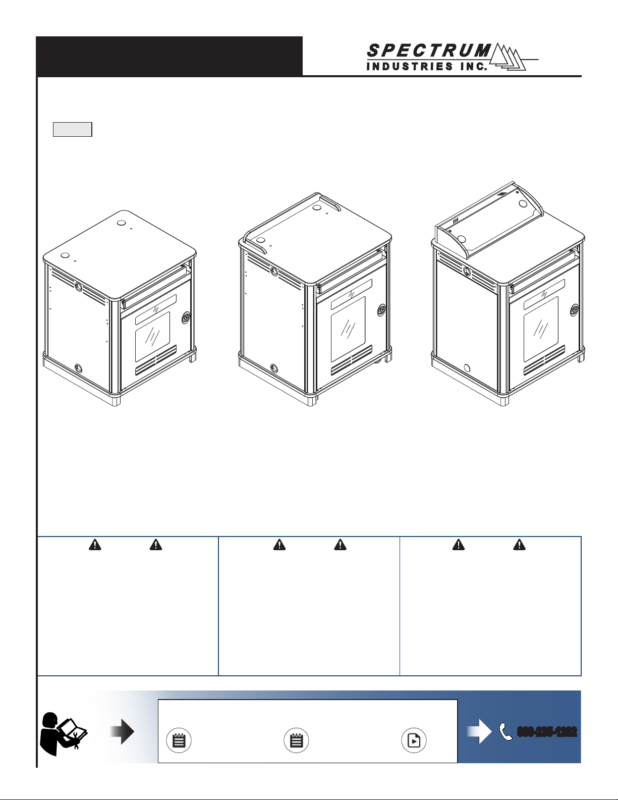
Link Lectern
55115
™
Media Manager Series
36”H shown with plain worksurface,
metal side panels, instructor-side
door and keyboard tray
Important
Before using this product:
• Read this manual
• Comply with all safety and operating instructions
• Ensure all parts and correct quantities are included
Any parts damaged during shipment must be reported within 5
days of receipt. To report information regarding missing parts or
damage, to purchase parts or accessories, or if you have any
questions, please contact us.
Thank you for purchasing Spectrum products!
??
41”H shown with surround,
metal side panels, instructorside door, and keyboard tray
Important
Avant d’utiliser ce produit:
• Veillez à lire ce guide
• Respectez les consignes de sécurité et d’utilisation
• Vériez que vous disposez de toutes les pièces
nécessaires à l’installation
Les pièces endommagées pendant le transport doivent faire
l’objet d’un rapport dans les 5 jours de leur réception. Veuillez
prendre contact avec nous si des pièces manquent ou sont
abîmées, si vous avez des questions, ou encore pour acheter
des pièces ou des accessoires.
Merci pour votre achat d’un produit Spectrum!
http://www.spectrumfurniture.com
41”H shown with Overbridge
Control Console, laminate side
panels, instructor-side door, and
keyboard tray
Importante
Antes de utilizar este producto:
• Lea este manual
• Cumpla con todas las instrucciones de prevención de
accidentes y operativas
• Revise que todas las partes y las cantidades correctas
estén incluidas
Si alguna parte se dañó durante el embarque, deberá reportarla
en un lapso de 5 días a partir de la recepción. Para reportar
cualquier información sobre partes faltantes o dañadas, para
adquirirlas o comprar accesorios, o bien, si tiene alguna duda,
póngase en contacto con nosotros.
¡Gracias por adquirir productos Spectrum!
Owner’s Manual
Le manuel du propriétaire
El manual del propietario
Specs
Spécications
Especicaciones
Video
Vidéo
Vídeo
800-235-1262
0120237R4 Page 1 of 17
Page 2
Hardware
(6) 053310
1/4-20 x 40mm
JC bolts
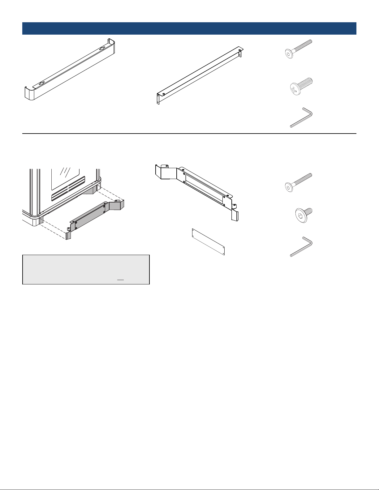
(2) 0119974
Side skirt
Optional Toe Kick Kit
(included with select congurations)
Note: If the toe kick will be anchored to the oor, (4) fasteners are required that will work with the 1/2” diameter holes
on the toe kick. Due to the wide variety of ooring materials
and conditions possible, anchor fasteners are not provided.
(1) 0119525
Audience-side skirt
(1) 0119531
Toe Kick
(1) 0118614
Toe Kick Plate
(4) 0100167
8-32 x 1/2” PH
Thread-cutting
screw
(1) 025039
4mm Hex
wrench
(4) 053310
1/4-20 x 40mm
JC bolts
(4) 052605
1/4-20 x 15mm
JC bolts
(1) 025039
4mm Hex
wrench
0120237R4 Page 2 of 17
Page 3
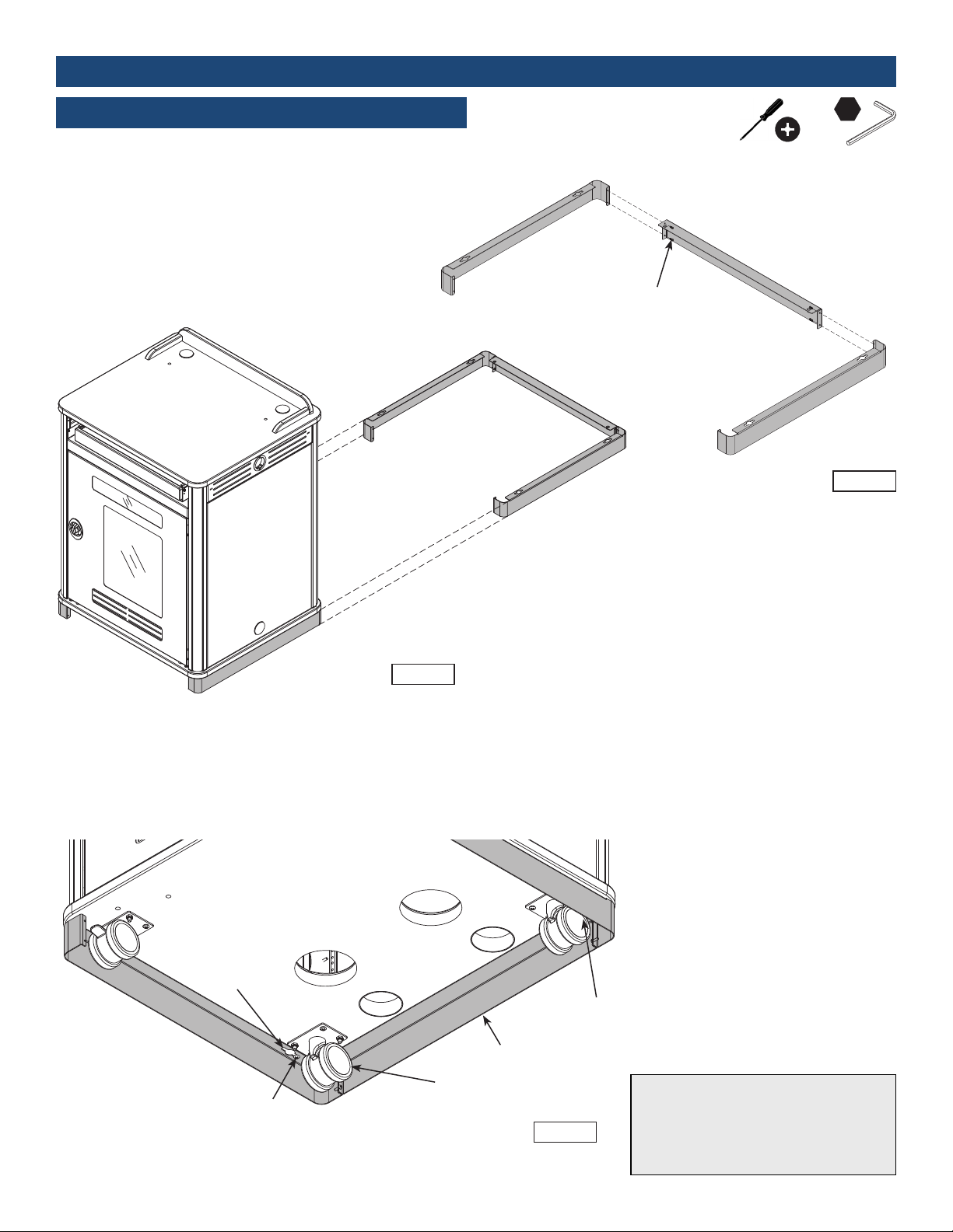
Assembly / Setup
1. Install 3-piece skirt
1. Attach the two side skirts to the audience-side skirt with (4)
8-32 x 1/2” PH Thread-cutting screws. Figure 1.1.
2. Move lectern into position over the assembled skirt as
shown. Figure 1.2.
Link Lectern
Side skirt
Skirt Assembly
4mm
Audience-side skirt
8-32 x 1/2” PH
Thread-cutting screws
(4 required)
Side skirt
Figure 1.1
Instructor-side
3. Hook the skirt keyhole slot at the end of each side skirt over the preinstalled #14 x 7/8” PHSM screw. Figure 1.3.
4. From inside the lectern (on audience-side) , install (2) 1/4-20 x 40mm
JC bolts through the base panel to secure the assembled skirt, and
tighten securely.
Keyhole
slot
#14 x 7/8” PHSM
(pre-installed)
Figure 1.2
1/4-20 x 40mm JC bolt
(install from inside lectern)
1/4-20 x 40mm JC bolt
(install from inside lectern)
Assembled skirt
Figure 1.3
Note: The skirt is designed to be easily removable. It should be removed if the lectern
will be moved over long distances or thresholds to prevent damage to the skirt panels.
Do not tip lectern to remove or install!
0120237R4 Page 3 of 17
Page 4
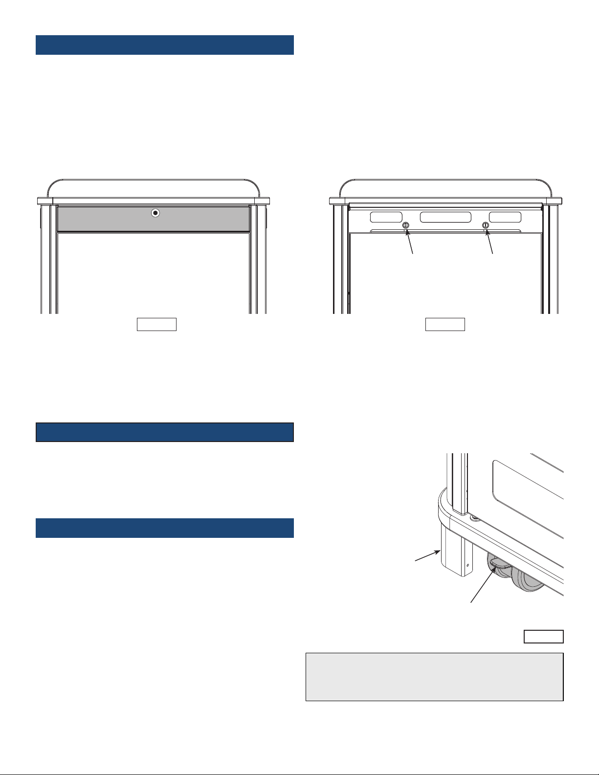
2. Audience-side Panel
The audience-side panel can easily be removed for full interior access.
To remove:
1. Push in the top of the narrow ip-up panel to access the locks.
(Do not pry open this panel). Figure 2.1.
2. Unlock both locks while supporting the audience-side panel. Figure 2.2.
3. Lift out the panel.
Push Here
Narrow ip-up panel
Audience-side
Figure 2.1 Figure 2.2
To Flip-up
panel
3. Caster Operation
1. Lock the brake levers to lock movement of the casters.
(Two instructor-side casters only). Figure 3.
2. To resume operation, lift up on brake levers.
Lock
Audience-side
panel
Lock
4. Moving and Parking the Lectern
• Before moving, unplug and secure all power cords.
• Close and lock doors.
• Lower any ip-up shelves.
• Remove any items from the top of the worksurface.
• Unlock the casters.
• Push slowly and carefully. Do not move over uneven or irregular surfaces.
• Do not allow children to move.
• Lock the casters after moving.
• Do not park unit in areas of heavy trafc.
• Do not run power cords across hallways, classrooms, or areas where
they will be walked on.
When lectern is unattended:
• Do not leave in areas where children have access.
• Keep doors closed and locked.
• Keep casters locked.
Skirt
Brake lever
Figure 3
Note: The skirt is designed to be easily removable. It should be removed
if the lectern will be moved over long distances or thresholds to prevent
damage to the skirt panels.
Do not tip lectern to remove or install!
0120237R4 Page 4 of 17
Page 5
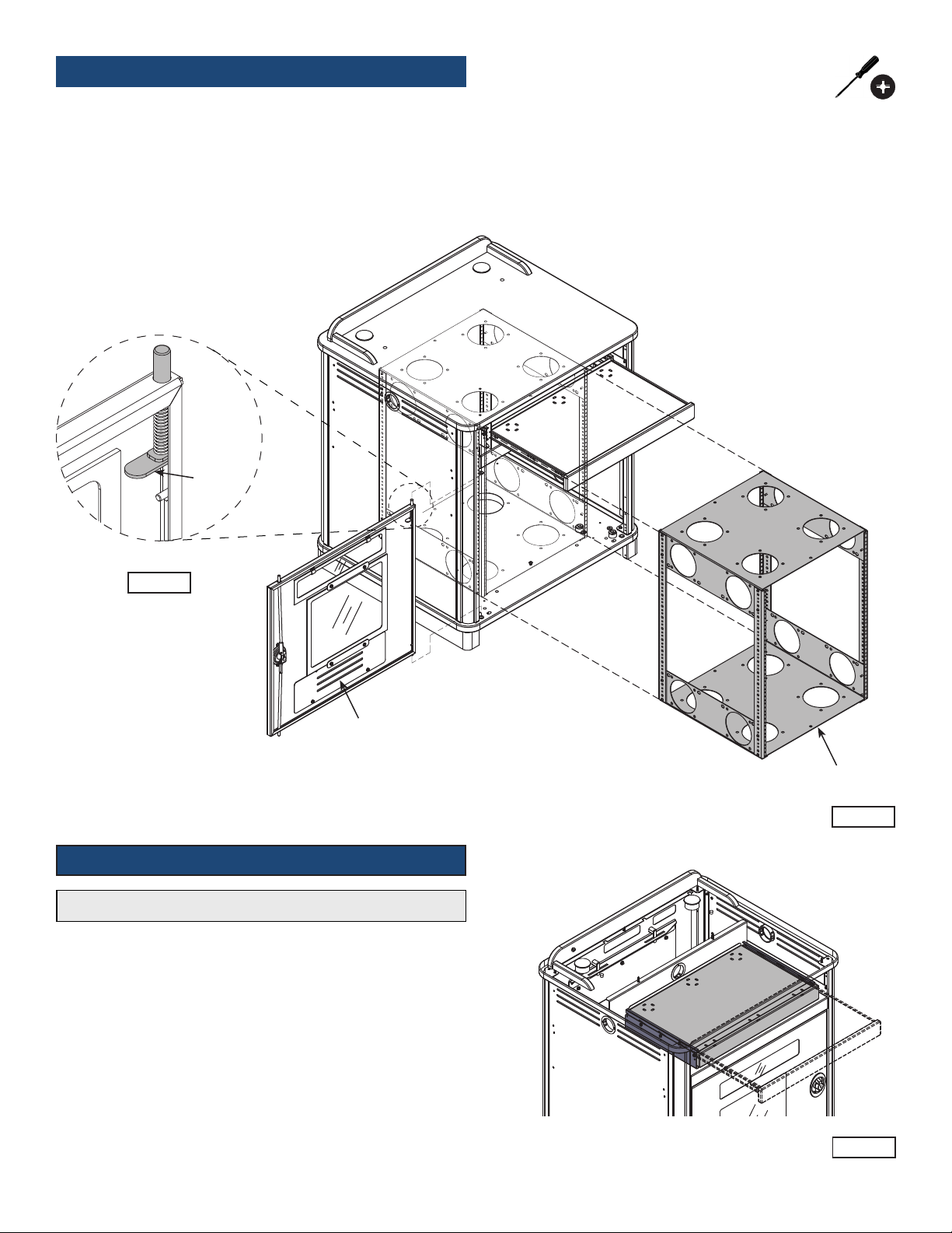
Optional Rack Cube
The removable rack cube simplies installation by providing the ability to
integrate equipment remotely for installation into the lectern at a later date.
It provides mounting capabilities for multiple cooling fans if necessary.
Compatible with most 4.75” cooling fans with 4.13” mounting hole spacing.
Figure 4.2.
1. To remove the rack cube, open or remove the doors. Figure 4.1.
2. Unscrew the #14 x 7/8” PHSM screw from the cube, and slide out.
Figure 4.2.
Quickrelease
lever
Figure 4.1
Removable door
(can be installed to
be hinged from left
or right-side)
Optional Keyboard Tray / Drawer
Note: Can be used as a keyboard tray, or ipped and used as a drawer.
1. To ip, pull out the tray and locate the black plastic lever on each
slide. Figure 5.
2. Release the levers on the slides while pulling the tray out.
3. Flip the tray, re-align the slides, and push back in.
Removable
Rack Cube
Figure 4.2
Keyboard
Tray
Figure 5
0120237R4 Page 5 of 17
Page 6
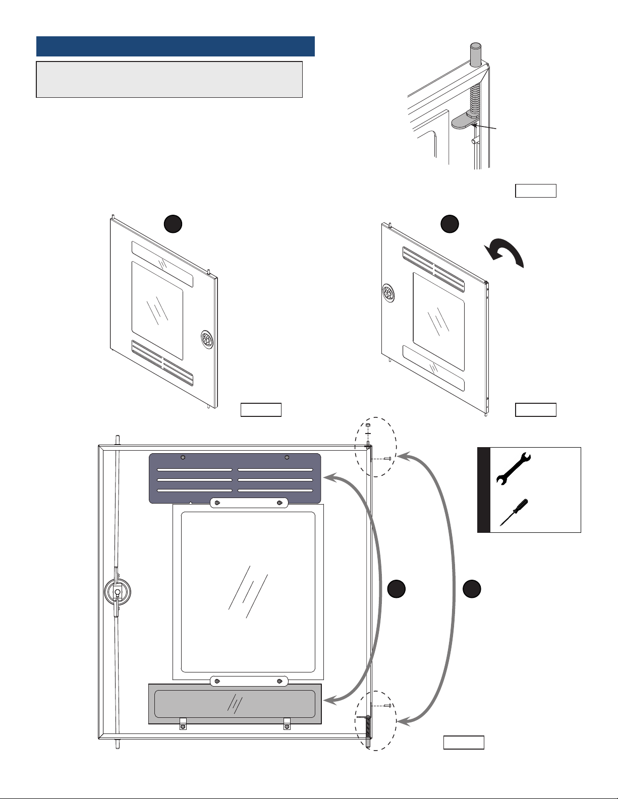
Optional Quick-Release Instructor-Side Door
The door can easily be removed for easier access using the quick-release
hinge lever located on the upper hinge pin of each door. Figure 6.1. To
remove, lift the lever while lifting out the door.
The door can be installed to be hinged from the left or right-side.
To switch the hinge side:
1. Remove the door using the quick-release lever. Figure 6.2.
2. Rotate the door 180°. Figure 6.3.
3. The vented panel should be located on the bottom of the door.
Switch the lower vented metal panel with the upper acrylic panel
(requires removing or loosening 8-32 nuts.) Figure 6.4.
4. Switch the corner hinge components as shown and tighten securely.
5. Re-install the door.
1 2
Hinged on left
Quick-release
lever
Figure 6.1
180°
Figure 6.2
3 4
Hinged on right
Figure 6.3
Tools Required
11/32” and
3/8” or
adjustable
wrench
Phillips
screwdriver
Figure 6.4
0120237R4 Page 6 of 17
Page 7
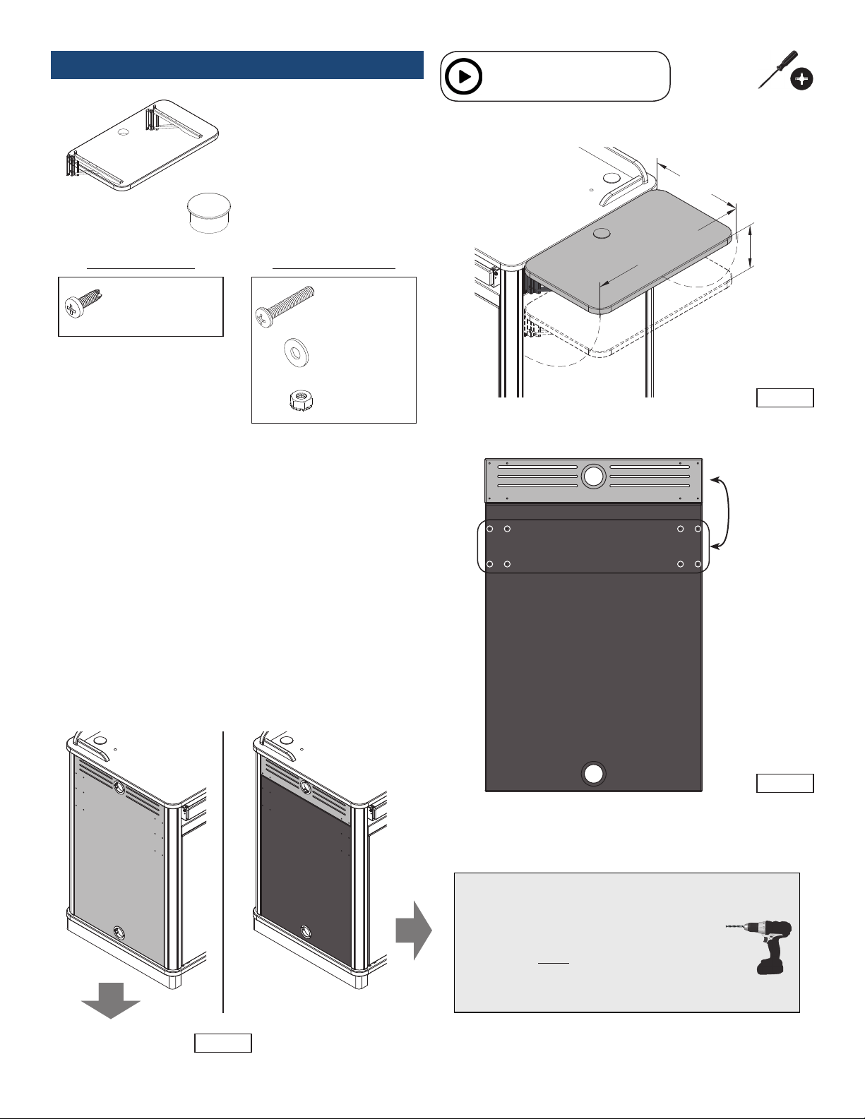
Optional Flip-up Shelf
(1) Flip-up shelf
assembly
(1) 039622
2” Grommet
For laminate side panelsFor metal side panels
Installation video available
See www.spectrumfurniture.com
26”D
[66 cm]
15.25”W
[38.7 cm]
7”D
[17.8 cm]
(8) 0100167
8-32 x 1/2” PH
Thread-cutting screw
(8) 051696
8-32 x 1” PHMS
(8) 0285
3/16 Flat Steel
Washer
(8) 021588
8-32 Keps Nut
1. Determine:
• The side of the lectern the shelf will be installed. (Left or right)
• The shelf position: (Upper or lower)
• Type of side panels your lectern has (metal or laminate) Figure 7A
Figure 7
Upper shelf
position holes
Lower shelf
position holes
Laminate Side Panel
(interior view)
Proceed to Step 2
Figure 7A
Figure 7B
LaminateMetal
Attaching to laminate side panels:
1. Open the lectern door and remove the rack cube
(if equipped).
2. From inside the lectern, use a drill with a 3/16”
drill bit and slowly drill out the corresponding
pre-drilled pilot holes located on the laminate
side panel. Figure 7B. Masking tape can be
used on the exterior to minimize chip-out.
0120237R4 Page 7 of 17
Drill with
3/16” drill bit
Page 8

2. Attach shelf brackets to lectern:
1. Extend and lock each folding shelf bracket into the horizontal position.
2. Select the fasteners needed (Metal or laminate side panels)
3. Install the (4) lower screws into the side panel at the preferred height
leaving about 1/4” of threads exposed.
4. Set the shelf assembly onto the (4) lower screws using the notched brackets.
5. Secure the shelf assembly by installing the (4) upper screws.
6. Tighten all 8 screws securely.
7. Install 2” grommet in shelf.
Metal side panel fasteners
(4) 8-32 x 1/2” PH Thread-cutting screws
Laminate side panel fasteners
(4) 8-32 x 1” PHMS
(4) 3/16” Flat steel washers
(4) 8-32 Keps nuts
Shelf bracket
8-32 x 1” PHMS in
3/16” drilled hole
from Figure 1B
3/16” Flat steel
washer
8-32 Keps nut
(use 11/32” wrench)
Laminate side panel
(2) Folding
shelf bracket
2” Grommet
Flip-up shelf
8-32 x 1/2” PH
thread-cutting screws
(Install lower 4 rst)
Figure 7D
Figure 7C
3. Operation:
Operation
The shelf will automatically lock into place when lifted into the horizontal
position with the levers released. Figure 7E. To lower or ip-up the shelf,
press and hold the shelf bracket levers while slowly lowering or raising the
shelf. Do not move the lectern while the shelf is in the horizontal position.
Note: Power and communication wiring for document cameras, laptop
computers, and / or projectors placed on the ip-up shelf should be
routed on top of the audience-side of the shelf. Use of the shelf grommet
hole for wiring will result in pinching of the cords when the shelf is folded.
Release lever
(press here)
CAUTION
Keep clear of pinch points during shelf movement.
Do not exceed 35 lbs [15.9 kg] of weight on shelf.
Folding shelf
bracket
Figure 7E
0120237R4 Page 8 of 17
Page 9
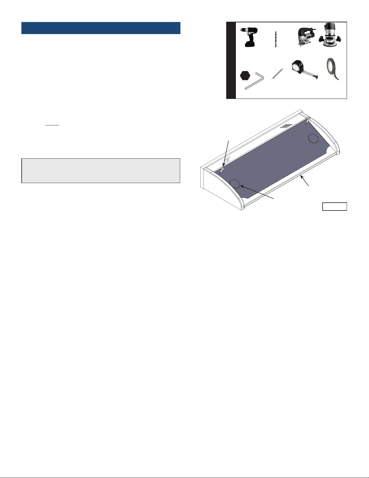
Optional Overbridge Insert Panel Cutouts
1. Before you begin, refer to the panel dimensions in Figure 8B for
maximum recommended cutout sizes.
2. Identify the size and position (left, centered, or right) of each cutout
needed.
3. Identify the depth of your device to verify it will not interfere with the
worksurface or any other objects under the overbridge when the
panel is attached. Figure 8C.
4. When the cutout location(s) have been determined, locate and mark the
exact cutout area(s) on the panel with a pencil. Note: Using masking
tape on cut lines will minimize laminate chipping while cutting.
5. Carefully make the cutout(s) in the panel using a jigsaw or router.
6. Set the panel into the overbridge frame opening. Note: It may be
necessary in some cases to install the electronic device into the
panel before attaching the panel to the overbridge.
7. Secure with (2) 1/4-20 x 35mm JC bolts and tighten securely.
8. Install (2) 2” grommets.
Note: The overbridge panel is symmetrical. Rotating or ipping the
panel 180° and re-attaching to the overbridge will allow you to place the
cutout on the opposite side of the overbridge if necessary.
Tools Required
4mm
1/4-20 x 35mm
JC bolt
(2 required)
Drill bit
Pencil Masking
Jigsaw or routerDrill
Measuring
Device
Overbridge
panel
Overbridge frame
2” grommet
tape
Figure 8A
0120237R4 Page 9 of 17
Page 10

Overbridge panel
Max cutout area
Overbridge
Section View
Note: The Overbridge Control Console™ has been designed
for many of the currently available controllers on the market,
however, modied cutouts should be reviewed by Spectrum
to ensure clearance of brackets, keyboard slides, or other
objects under the worksurface.
Contact Spectrum to specify cutout size(s) and location(s).
Cutouts can be made in the blank insert panel by the
customer after the lectern has been purchased, but are
only recommended within the cutout area shown.
2”
Grommet
Figure 8B
Worksurface opening below
Worksurface
Note: The max cutout areas shown
are general recommendations only.
The nal location of the cutout(s) on
the panel will be determined by:
• The size of the cutout(s)
• Location preference of each device
(left, centered, right)
• The vertical depth of the installed
device
• The available worksurface opening
under the overbridge on your
specic Spectrum lectern.
Rack Cube
Figure 8C
0120237R4 Page 10 of 17
Page 11
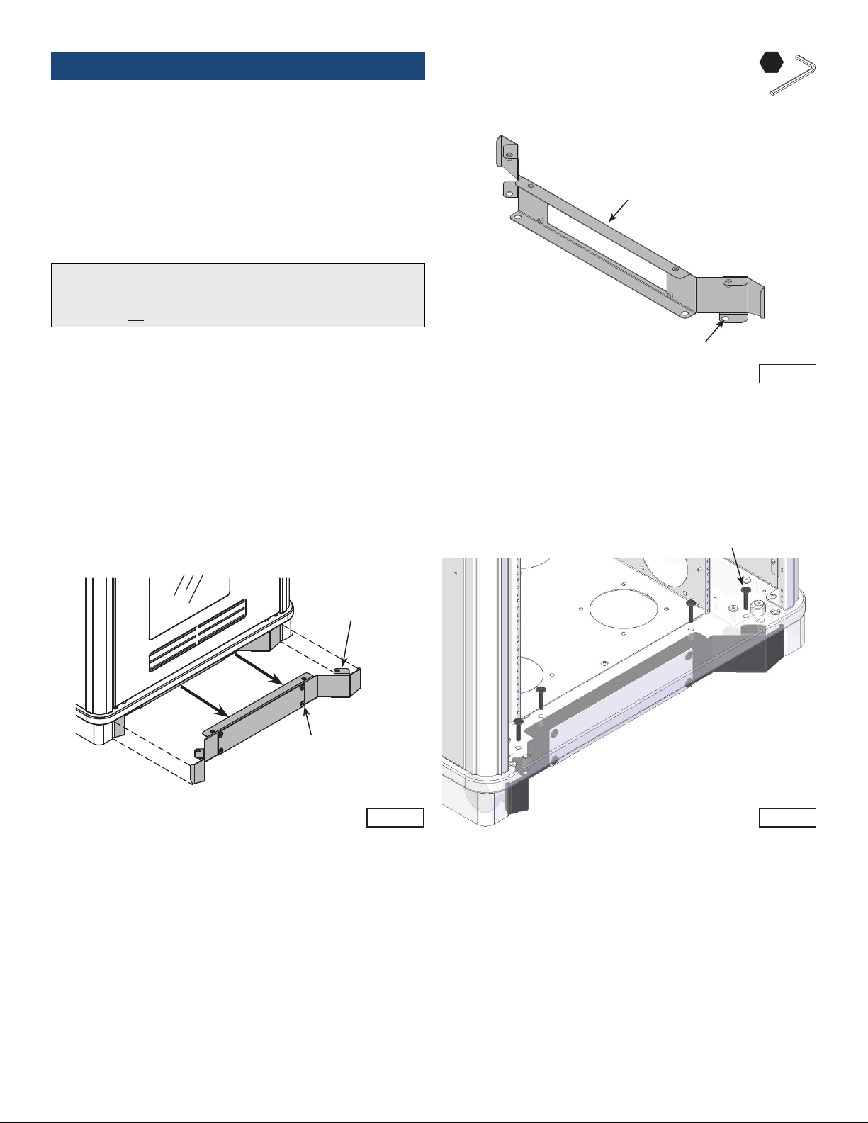
Optional Toe Kick
1. Position the toe kick panel on the oor in the preferred nal lectern
location. Figure 9A.
2. Mark the (4) mounting hole locations onto the oor.
(The toe kick mounting holes are 1/2” dia.)
3. Drill suitable holes into the oor and anchor the toe kick with
appropriate fasteners.
4. At this point, wiring connections can be made under the lectern with
easier access to the base panel grommet holes.
4mm
Toe kick panel
Note: If the toe kick will be anchored to the oor, (4) fasteners are
required that will work with the 1/2” diameter holes on the toe kick. Due
to the wide variety of ooring materials and conditions possible, anchor
fasteners are not provided.
5. Move lectern into position over the anchored toe kick. Figure 9B.
6. Align the (4) base panel mounting holes (instructor-side) with the
toe kick panel mounting holes.
7. Attach toe kick plate with (4) 1/4-20 x 15mm JC bolts.
Link Lectern
Toe kick panel
anchored to oor
Floor
(4) 1/2” mounting
holes for oor anchors
Figure 9A
8. Open or remove both doors.
9. Install (4) 1/4-20 x 40mm JC bolts through the base panel to secure,
and tighten securely. Figure 9C.
1/4-20 x 40mm JC bolts
(4 required)
Toe Kick Plate
1/4-20 x 15mm JC bolt
(4 required)
Figure 9CFigure 9B
0120237R4 Page 11 of 17
Page 12

Accessories
(Customer-installed when purchased separately)
15RU Rack Cube - 55384
12RU Rack Cube - 55197
• Provides the ability to integrate
equipment remotely before
installation into the lectern
• One rack cube can be installed
into the Link Lectern
• Polyethylene slides on bottom for
easy removal
• Can be secured to base panel
• Cooling fan compatible
• Color: black
26”D
[66 cm]
15RU (41”H Link)12RU (36”H Link)
15.25”W
[38.7 cm]
7”D
[17.8 cm]
Rack rail: 15RU front and rear (41”H Link)
Dimensions 15RU
Cube:
Dimensions 12RU
Cube:
Mounts for cooling
fans:
Unit weight: 21 lb [9.5 kg] 15RU Cube
Shipping weight: 23 lb [10.4 kg 15RU Cube
Flip-Up Shelf - 55385
• Shelf hinges lock into place in the upright position
• Includes 2” grommet
• Available in White Chalk Dry Erase laminate
• Two height-positions available
Weight capacity: 35 lb [15.9 kg]
Dimensions: 15.25”W [38.7 cm] x 26”D [66 cm] x 1”H [2.54 cm]
Unit weight: 13.25 lb [6 kg]
Shipping weight: 17 lb [7.7 kg]
12RU front and rear (36”H Link)
19.125”W [48.58 cm] x 19.031”D [48.34 cm] x
26.625”H [67.63 cm]
19.125”W [48.58 cm] x 19.031”D [48.34 cm] x
21.375”H [54.29 cm]
Compatible with most 4.7” fans with 4.13” mounting
hole spacing (12 mounting locations available)
19 lb [8.6 kg] 12RU Cube
22 lb [10 kg] 12RU Cube
Note: The unit requires a 7” diameter of clearance to work with
Qi-enabled phones placed in any orientation. The 3” dia cutout
should be located on the worksurface at least 3.5” from any edge.
Note: Power and communication wiring for document cameras, laptop
computers, and/or projectors placed on the ip-up shelf should be routed
on top of the audience-side of the shelf. Use of the shelf grommet hole
for wiring will result in pinching of the cords when the shelf is folded.
EM Wireless Charging Pad - 99057
• Uses electromagnetic technology to charge Qi V1.2 compliant IC devices
("Qi" enabled)
• LED to conrm pairing / charging
• Security tab prevents theft
• Requires 3” round cutout to be made by customer
• UL-certied
Cutout required: 3" dia (by customer)
Input: DC 5V (with included DC5V.2A power adapter)
Output: 5W max (with included DC5V.2A power adapter)
Power cord: 8’ [244 cm] with DC jack
Dimensions: 3.5” dia [8.9 cm] x 1.125”H [2.9 cm]
Shipping weight: 1 lb [.45 kg]
0120237R4 Page 12 of 17
Page 13

Keyboard Tray - 55386
• Installed centered using pre-drilled mounting holes under the worksurface
• Can be used as a keyboard tray or ipped and used as a storage drawer
• Wire management slots in tray
Dimensions: 22”W [55.9 cm] x 13.8”D [35 cm] x 2.1”H [5.3 cm]
Slides: 14” [35.6 cm] full-extension
Weight capacity: 25 lb [11.4 kg]
Unit weight: 12 lb [5.4 kg]
Shipping weight: 14 lb [6.4 kg]
2RU Rack Rail Kit - 55113
• Adds an additional 2RU to lectern
• (Keyboard Tray needs to be removed to install)
Rack Units: 2RU
Shipping weight: 1 lb (.5 kg)
Customized Logo Panel - 55111
• Attaches to audience-side of lectern
• Available with black, white, or matching laminate backer
• To get panel customized-contact Spectrum for details
• New logos require a rst time logo charge
Dimensions: 18.5“W [47 cm] x 12”H [30.5 cm]
Available logo area: 16.5”W [41.9 cm] x 10”H [25.4 cm]
Shipping weight: 3.25 lb [1.5 kg]
Logo area available
0120237R4 Page 13 of 17
Page 14

Insert panels are available to customers needing a replacement panel or different cutouts for technology upgrades.
Overbridge Insert Panel-Medium
96504 - Blank panel-Medium
96504mod - Panel with cutout(s)
• Panel for overbridge version only (overbridge not available separately)
• Contact Spectrum to specify cutout size(s) and position(s)
• Includes two 2” [5.08 cm] grommets with covers
• Customer-installed
Dimensions: 27.25”W [69.2 cm] x 9”D [22.9 cm] x .79”H [2 cm]
Unit weight: N/A
Shipping weight: 8.5 lb [3.9 kg]
Two-piece Overbridge Insert Panel-Medium
96504 - Blank panel (split)-Medium (2 required)
• Split panel for overbridge version only
• Contact Spectrum to specify cutout size(s) and position(s)
• Includes 2” [5.08 cm] grommets with covers
• Customer-installed
Dimensions: 13.625”W [34.6 cm] x 9”D [22.86 cm] x .79”H [2 cm]
Unit weight: N/A
Shipping weight: 4.25 lb [1.9 kg]
Instructor-Side Door
55114 - 41”H
55387 - 36”H
• Dual-bolt lock provides security
• Quick-release hinge allows easy removal for full-access
• Door can be installed to be hinged from the left or right
• Two acrylic panels provide ability to monitor internal components
• Ventilated bottom panel
Dimensions: 41”H Lectern: 26.3”W [66.8 cm] x .75”D [1.9 cm] x
36”H Lectern: 26.3”W [66.8 cm] x .75”D [1.9 cm] x
Shipping weight: 10 lb [4.5 kg]
Toe Kick Kit - 55110
• Attaches to oor and lectern when mobility is not
necessary or desired (oor fasteners not included)
• Conceals casters
• Includes access panel
• Shipping weight: 12 lb [5.4 kg]
28.3”H [71.8 cm]
23.28”H [59.1 cm]
Skirt
Toe Kick
0120237R4 Page 14 of 17
Page 15

Power Module - 99058
• (2) AC power receptacles
• (2) USB charge ports
• Aluminum housing and ange
• Thumbscrew clamps
Cutout required: 5.65”W [14.35 cm] x 1.65”D [4.19 cm]
Power cord: 10’ [305 cm] 14AWG *3C power cord
Power receptacles: 125V, 60hz, 15A tamper-resistant
USB charging ports: 2.1A (10.5W) (not data-compatible)
Dimensions: 6.38”W [16.2 cm] x 2.36”D [6 cm] x 3.54”H [9 cm]
Unit weight: 2 lb [.9 kg]
Shipping weight: 2.35 lb [1 kg]
Cooling Fan for Media Manager Series Lecterns - 99051
• Exhausts hot air from inside lectern
• Installs inside lectern at top of rack cabinet
• Mounts to side panel vent slots with two screws
• Customer-installed
• Requires worksurface cutout
• ETL-certied
• Available in black, silver, or white
• Customer-installed
(Available position on
base with rack cube)
Electric Fan: • Voltage: 115VAC
Power cord: 18ga, 48” nominal length, 6A 125V~ (2 prong plug)
Mounting bracket • 16-gauge steel
Unit weight: 2.3 lb [1.05 kg]
Shipping weight: 3 lb [1.36 kg]
Universal Cord Reel Kit - 99037
• Includes universal mounting bracket
• Mounts inside lectern to base panel
• Adjustable ball stop and releasable cord-locking
ratchet holds the cord at any length up to 15’
• cUL listed
Power cord: 15’ nominal, 12 AWG retractable power cord
Power
receptacles:
Universal
mounting bracket
Unit weight: 10 lb [4.5 kg]
Shipping weight: 10.8 lb [4.9 kg]
The cord reel is intended to provide temporary access to electrical outlets for
Spectrum mobile lecterns. Check local electrical codes prior to installation.
(single phase)
• Power: 5.5W
• Current: .08A
• 1450 RPM
• Dimensions:
119 mm x 119 mm
• Ball Bearing
• Noise: 28 dB
• Black powder coat
• Mounting screws included
• Molded 3-prong male plug with 15A breaker
and reset button
• Tri-tap (3-outlet) receptacle
• 16-gauge steel
• Black powder coat
• Includes mounting screws
• Air ow: 49.4 CFM
(1.40m³/min)
• Frame material:
Aluminum
• Blade material:
Polycarbonate,
Fiberglass reinforced
See spectrumfurniture.com for the latest
accessories and detailed warranty information.
0120237R4 Page 15 of 17
Page 16
Important Safety and Care Instructions
• Read this owner’s manual before assembly or operation.
• Do not allow children to move the cart.
• Proceed slowly and carefully when moving the cart.
• For indoor use only. Do not install or store the cart where it will be exposed to moisture.
• Do not block the ventilation openings.
• Avoid uneven loading of the equipment into the cart. Uneven weight
distribution could cause the cart to tip when the cart is moving.
• Do not allow anyone to sit, stand, or climb on the cart.
• Use a damp, soft-cloth, or sponge, with mild soap or detergent solution to
clean dirty surfaces. Do not use harsh solvents or abrasives.
• This cart is intended for institutional use. It does not have any userserviceable parts or user-maintenance requirements. If servicing is
necessary, please contact Spectrum Industries for assistance.
Warning - Relocating audio and/or video equipment to furniture not speci cally
designed to support audio and/or video equipment may result in death or serious
injury due to the furnishing collapsing or over turning onto a child.
Warning - Death or serious injury may occur when children climb
on audio and/or video equipment furniture. A remote control or toys
placed on the furnishing may encourage a child to climb on the
furnishing and as a result the furnishing may tip over on to the child.
Consignes importantes de sécurité et d’entretien
• Lire ce guide d’utilisation avant l’assemblage ou l’utilisation.
• Interdire aux enfants de déplacer l’armoire.
• Déplacer l’armoire lentement et prudemment.
• Utilisation à l’intérieur uniquement. Ne pas assembler et ne pas ranger
l’armoire dans un endroit humide.
• Ne pas boucher les prises d’air de ventilation.
• Éviter le chargement mal réparti de l’équipement sur l’armoire. Un chargement
mal réparti risque de faire basculer l’armoire en déplacement.
• Interdire à quiconque de s’asseoir, de se tenir debout ou de grimper sur l’armoire.
• Passer un chiffon doux ou une éponge, imbibés de solution nettoyante ou de savon
liquide doux, sur les surfaces sales. Ne pas utiliser des solvants rudes ou des abrasifs.
• Cette classe mobile est destinée à un usage collectif. Elle ne contient
aucune pièce susceptible d’être réparée par l’utilisateur et ne nécessite
aucun entretien de la part de celui-ci. Si une maintenance est requise,
communiquer avec Spectrum Industries pour obtenir de l’aide.
Avertissement - Reloger un équipement audio ou vidéo sur un meuble non
conçu pour supporter cet équipement pourrait entraîner de graves blessures, voire
la mort, à la suite de l’effondrement du meuble ou de sa chute sur un enfant.
Avertissement - Un enfant qui grimpe sur un meuble d’équipement
audio ou vidéo pourrait subir des blessures graves ou mortelles. Une
télécommande ou des jouets placés sur le meuble risquent d’inciter un
enfant à y grimper : le meuble pourrait alors basculer et écraser l’enfant.
Electrical Safety:
• Keep the power switch in the OFF position before plugging or
unplugging from the wall outlet.
• Turn OFF the devices before plugging them into the cart.
• Ensure total device / equipment load does not exceed 12-amps.
• Do not plug the power cord into an extension cord.
• Inspect the power cords for damage before each use. Do not use
power cords that are damaged.
• Unplug power cord from electrical outlet by gripping the plug. Do not
unplug the power cord by pulling only on the cord.
• Do not step on, drive over, drag, or place objects on the power cord.
• For added safety, plug the cart into a grounded outlet controlled by a
GFI (Ground Fault Interrupter) circuit breaker.
• Damaged electrical components can create signi cant hazards to
users and is not covered by the warranty. Repairs should always be
performed by a quali ed electrician.
• Electrical devices are not toys. Children are often unaware of the
hazards associated with electrical devices. This cart must always be
used by adults or with adult supervision.
Consignes de sécurité en électricité
• Mettre d’abord l’interrupteur sur Arrêt avant de brancher ou de
débrancher la prise.
• Éteindre les appareils avant de les brancher à l’armoire.
• Assurez-vous que la charge totale appareils / équipements n’excède pas 12 A.
• Ne pas brancher le cordon d’alimentation sur une rallonge.
• Véri er que les cordons d’alimentation sont intacts avant chaque
utilisation. Ne pas les utiliser s’il sont abîmés.
• Pour débrancher le cordon de la prise murale, saisir son bouton
isolant et tirer; ne pas tirer le cordon.
• Ne pas marcher, ne pas rouler et ne pas placer des objets sur le
cordon d’alimentation; ne pas le traîner.
• Pour plus de sécurité, brancher l’armoire sur une prise mise à la terre
protégée par un disjoncteur de fuite de terre.
• Les composants électriques abîmés risquent d’exposer les utilisateurs
à de graves dangers; ils ne sont pas couverts pas la garantie.
Toujours con er les réparations à un électricien quali é.
• Les appareils électriques ne sont pas des jouets. Les enfants
n’ont souvent pas conscience des dangers associés aux appareils
électriques. Cette armoire doit donc être toujours utilisée par un adulte,
ou sous la surveillance d’un adulte.
Instrucciones importantes de prevención de accidentes y cuidado
• Lea este manual del propietario antes de la instalación u operación.
• No permita que los niños muevan el carro.
• Proceda lenta y cuidadosamente al mover el carro.
• Solo para uso en interiores. No instale o guarde el carro donde quede
expuesto a la humedad.
• No obstruya las rendijas de ventilación.
• Evite cargar el equipo de forma desigual dentro del carro. La distribución asimétrica
del peso podría provocar que el carro se vuelque al momento de moverlo.
• No permita que nadie se siente, pare o suba al carro.
• Para limpiar las super cies sucias, utilice un paño, trapo suave o esponja con jabón
neutro o una solución de detergente. No utilice solventes o abrasivos ásperos.
• El uso convencional de este carro es institucional. No contiene ninguna
parte que pueda ser reparada ni requiere de mantenimiento por parte del
usuario. Si fuera necesario darle mantenimiento, póngase en contacto con
Spectrum Industries para obtener asistencia.
Advertencia: reubicar equipo de audio y/o video a un mueble que no haya
sido diseñado especí camente para tal uso, puede provocar la muerte o
lesiones graves debido a que puede colapsarse o volcarse sobre un niño.
Advertencia: existe peligro de muerte o lesiones graves si los niños
se suben a un mueble de equipo de audio y/o video. Un control
remoto o juguete colocado sobre el mueble puede alentar a un niño a
subirse y provocar que el mueble se vuelque sobre el chico.
Prevención de accidentes eléctricos:
• Mantenga el interruptor de alimentación en la posición de OFF [apagado],
antes de enchufarlo o desenchufarlo del tomacorriente de pared.
• Apague los dispositivos antes de enchufarlos al carro.
• Revise que la carga total del dispositivo o del equipo no exceda los
12 amperios.
• No enchufe el cable de alimentación a un cable de extensión.
• Revise que el cable de alimentación no tenga ningún daño antes de
utilizarlo. No utilice cables de alimentación que estén dañados.
• Desconecte el cable de alimentación de la toma eléctrica sosteniendo
rmemente el enchufe. No desconecte el cable de alimentación
tirando solamente del cable.
• No se pare, circule, jale o coloque ningún objeto sobre el cable de
alimentación.
• Para mayor seguridad, enchufe el carro a una conexión a tierra
controlada por un interruptor de circuito GFI (interruptor de fallas de
conexión a tierra).
• Los componentes eléctricos dañados pueden implicar riesgos de
importancia para los usuarios, que no cubrirá la garantía. Un electricista
cali cado es quien deberá realizar siempre las reparaciones.
• Los dispositivos eléctricos no son juguetes. Los niños generalmente no están
conscientes de los riesgos asociados con los dispositivos eléctricos. Este
carro lo deberán utilizar siempre personas adultas o bajo su supervisión.
0120237R4 Page 16 of 17
Page 17
DESIGNED AND ASSEMBLED IN
CHIPPEWA FALLS
WISCONSIN.USA
Product Registration
Dear customer,
Spectrum Industries would like to thank you for your
purchase. Please take a moment to register your product
for valuable warranty and product information. Locate the
product and serial numbers on the label located either on
the inside of the front door, or under the main worksurface.
Record the numbers here to enter online.
If you have any questions or concerns about the product
you received, please contact us.
1-800-235-1262
Toll-free HELPLINE
spectrum@spectrumfurniture.com
Warranty
We will make it right for you!
Spectrum is committed to provide complete customer
satisfaction. Each of our products is manufactured from
the best materials available and each product is stringently
monitored throughout the production process through our
Quality Management System.
We expressly warrant that Spectrum products will be of
good quality and workmanship and free from defect for the
period set out in the warranty table from the date of delivery.
This warranty shall not apply to defects or damage resulting
from normal wear and tear, misuse, or unintended use, failure to follow instructions related to the product’s installation
or intended use, abuse, neglect, improper care, modifi cation
or repair not authorized by Spectrum, or any other cause
outside the control of Spectrum. Spectrum will, at its sole
option, either repair or replace the defective product.
See website for complete warranty terms:
spectrumfurniture.com/en/resources/warranty
Product Number:
Serial Number:
Learn more at:
spectrumfurniture.com/register
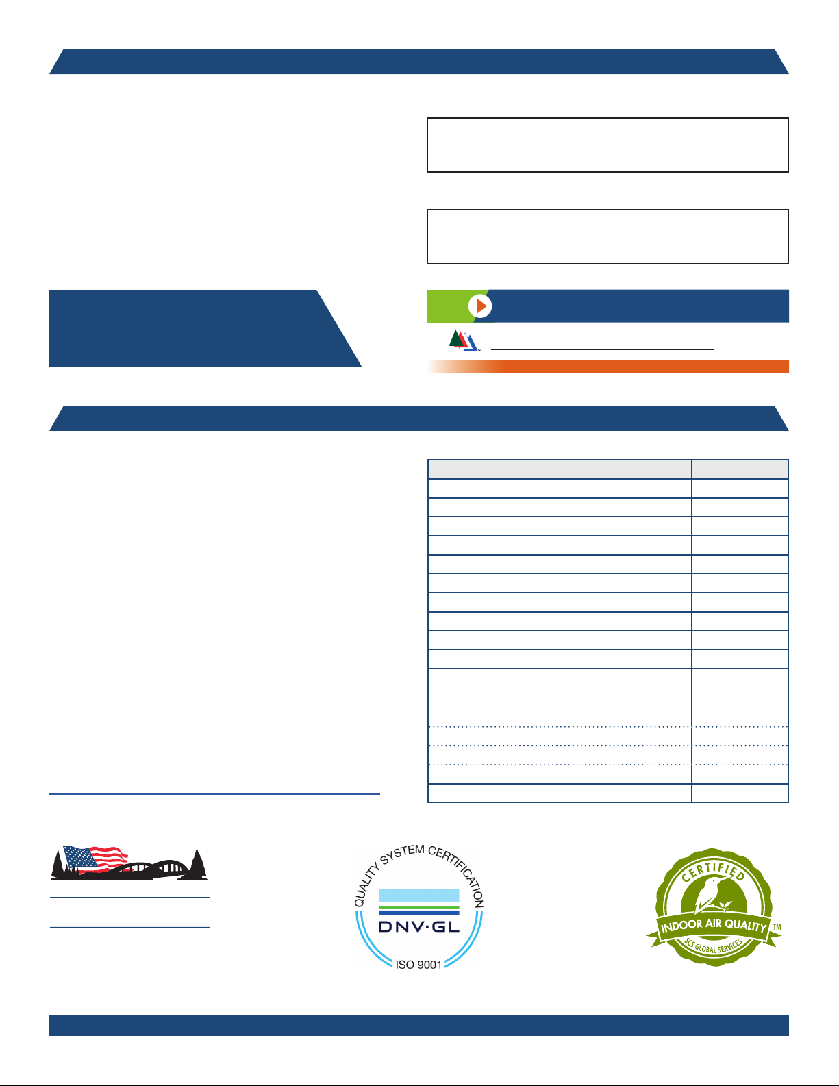
Item Warranty Period
Desk, table, cart and lectern chassis 10 Years
Electrical 2 Years
Flat panel monitor arms / gas spring / general parts 2 Years
Adjustable crank / electric legs and accessories 2 Years
Flat panel desk gas spring cylinders 2 Years
Height adjustable columns, lifts & accessories 2 Years
Casters & wheels 2 Years
Keyboard, mouse, trays 2 Years
Locks & keys 2 Years
Tubs, totes and other accessories 1 Year
Chairs
Structural components, including gas cylinders,
wood, metal and plastic parts (i.e., chair frames,
bases and control handles)
Consumable items (i.e., casters, glides, etc.) 5 Years
In-stock upholstery 5 Years
Arozzi chairs 2 Years
Customer supplied material No Warranty
7 Years
925 FIRST AVENUE, CHIPPEWA FALLS, WI 54729 / 800-235-1262 / 715-723-6750 / WWW.SPECTRUMFURNITURE.COM
Spectrum Industries Inc.
is Certifi ed ISO 9001:2015
© 2019 Spectrum Industries Inc., All rights reserved.
0120237R4 Page 17 of 17
 Loading...