

Page 1
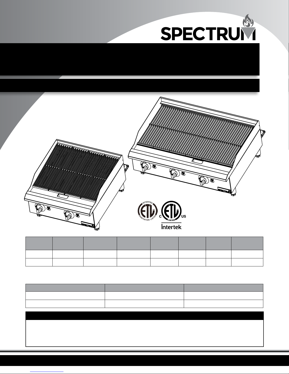
GCB-36R
Conforms to ANSI STD
Z83.11b-2009(R2012)
Certied to CSA
STD 1.8b-2009(R2012)
GCB-24R
3182799
MODEL
GCB-24R
GCB-36R
Note: Depth direction includes the regulator size.
CHAR BROILER SURFACE DIMENSIONS
WIDTH
IN. (MM)
24" (610 mm) 26.8" (680 mm) 15.6" (398 mm)
36" (915 mm) 26.8" (680 mm) 15.6" (398 mm)
MODEL WIDTH - IN. (MM) DEPTH - IN. (MM)
GCB-24R 24" (610 mm) 20" (510 mm)
GCB-36R 36" (915 mm) 20" (510 mm)
BEFORE OPERATING ANY EQUIPMENT, READ AND FAMILIARIZE YOURSELF WITH THESE USE AND SAFETY INSTRUCTIONS
Congratulations on your purchase of SPECTRUM commercial cooking equipment. SPECTRUM takes pride in the design
and quality of our products. When used as intended and with proper care and maintenance, you will experience years of
reliable operation from this equipment. To ensure best results, it is important that you read and follow the instructions in
this manual carefully. It’s important to save these instructions for future reference.
DEPTH
IN. (MM)
HEIGHT
IN. (MM)
# OF
BURNERS
2 40,000 80,000 6 / 10
3 40,000 120,000 6 / 10
BTU/PER
NAT/LP
TOTAL
BTU/HR
PRESSURE
IN. W.C
Page 2
Important For Future Reference
Please complete this information and retain this manual for the life of the equipment. For
Warranty Service and/or parts, this information is required.
Model Number Serial Number Date Purchased
WARNING: For your safety, do not store or use gasoline
or other ammable vapors or liquids in the vicinity of
! !
this or any other appliances. Keep the area free and
clear of combustibles. (See ANSI Z83. 14B, 1991).
WARNING: Improper installation, adjustment,
alteration, service or maintenance can cause property
! !
damage, injury, or death. Read the installation
operating and maintenance instructions thoroughly
before installing, or servicing this equipment.
WARNING: Instructions must be posted in a prominent
location. All safety precautions must be taken in the
! !
event the user smells gas. Safety information can be
obtained from your local gas supplier.
CAUTION: These models are designed, built, and sold for
commercial use only. If these models are positioned so
! !
the general public can use the equipment, make sure
that cautions, warnings, and operating instructions
are clearly posted near each unit so that anyone using
the equipment will use it correctly and not injure
themselves or harm the equipment.
AVERTISSEMENT: Pour votre sécurité, ne pas stocker ni
utiliser d'essence ou d'autres vapeurs ou liquides
inammables à proximité de cet appareil ou d'autres
appareils. Garder la zone libre de combustible.
(Voir la norme ANSI Z83. 14B, 1991).
AVERTISSEMENT: Une installation, un réglage, une
modication, un entretien ou peut causer des dommages
matériels, des blessures ou la mort. Lisez les
instructions d' exploitation et de maintenance d'installation
avant d'installer, ou sauvegarder cet équipement.
AVERTISSEMENT: Les instructions doit être achées dans
un endroit bien en vue. Toutes les mesures de sécurité
doit être prises en cas d'odeur de gaz. Les consignes
de sécurité peut être obtenue auprès de votre fournisseur
de gaz local.
ATTENTION: Ces modèles sont conçus, fabriqués et vendus
pour un usage commercial seulement. Si ces modèles
sont positionnés de sorte que le grand public peut
utiliser l'équipement, assurez-vous que mises en garde, les
avertissements et les instructions sont clairement achés unité
de sorte que toute personne utilisant l'équipement va l'utiliser
correctement et de ne pas nuire à injurethemselves
ou l'équipement.
WARNING: A factory authorized agent should handle
all maintenance and repair. Before doing any
! !
maintenance or repair, contact your authorized service
representative.
GAS PRESSURE
The appliance and its individual shuto valve (to be supplied by
user) must be disconnected from the gas supply piping system
during any pressure testing of that system at test pressures in
excess of ½ psi (3.45 kPa).
The appliance must be isolated from the gas supply piping
system by closing its individual manual shut-o valve during any
pressure testing of the gas supply piping system at test pressures
equal to or less than ½ psi (3.45 kPa).
2
AVERTISSEMENT: Un agent autorisé de l'usine doit traiter
tout l'entretien et la réparation. Avant de faire tout
entretien ou réparation, contactez votre représentant
de service autorisé.
PRESSION DE GAZ
L'appareil et la vanne d'arrêt individuel (à fournir par
l'utilisateur) doit être débranchés de la tuyauterie d'alimentation
en gaz pendant tout test de pression de ce système à des
pressions d' essai supérieures à ½ psi (3.45 kPa).
L'appareil doit être isolé du système de conduites d'alimentation
en gaz en fermant son robinet manuel d'arrêt individuel durant
tout test de pression du système de tuyauterie d'alimentation en
gaz à des pressions inférieures à ½ psi (3.45 kPa).
Page 3

Table of Contents
Specications .............................................................................. 1
Warnings ..................................................................................... 2
Table of Contents ....................................................................... 3
Introduction ................................................................................ 3
Safety Precautions ...................................................................... 4
Packaging .................................................................................... 4
Installation .................................................................................. 5
Conversion ................................................................................... 6
Lighting ....................................................................................... 7
Operation .................................................................................... 8
Cleaning, Care & Maintenance ................................................. 8
Troubleshooting ......................................................................... 9
Safety ............................................................................................ 9
Service & Repair ......................................................................... 9
Exploded View ......................................................................... 10
Spare Parts List ..........................................................................11
Limited Warranty ..................................................................... 12
Introduction
Congratulations on the purchase of your SPECTRUM machine. Please take
time to carefully read through this manual to ensure the machine is operated
and maintained properly, to ensure the best possible performance from the
product for many years.
SPECTRUM will not accept liability for the following if:
• The instructions in this manual have not been followed correctly.
• Non-authorized personnel have tampered with the machine.
• Non-original spare parts are used.
• The machine has not been handled and cleaned correctly.
• There is any use damage to the unit.
LOCATION OF DATA PLATE
The data plate is located on the side panel.
IMMEDIATELY INSPECT FOR SHIPPING DAMAGE
All containers should be examined for damage before and during unloading.
The freight carrier has assumed responsibility for its safe transit and delivery.
If equipment is received damaged, either apparent or concealed, a claim
must be made with the delivering carrier.
A. Apparent damage or loss must be noted on the freight bill at the time of
delivery. It must then be signed by the carrier representative (Driver). If
this is not done, the carrier may refuse the claim. The carrier can supply
the necessary forms.
B. If concealed damage or loss is not apparent until after equipment is
uncrated, a request for inspection must be made to the carrier within
15 days. The carrier should arrange an inspection. Be certain to keep all
contents and packaging material.
Installation should be performed by a qualied installer who thoroughly
read, understands and follows these instructions.
If you have questions concerning the installation, operation, maintenance or
service of this product, please contact WINCO.
Please keep this manual in a safe place for future use!
3
Page 4
Safety Precautions
DANGER: This symbol warns of imminent hazard which
will result in serious injury or death.
! !
WARNING: This symbol refers to a potential hazard
or unsafe practice, which could result in serious injury
! !
or death.
CAUTION: This symbol refers to a potential hazard
or unsafe practice, which could result in minor or
! !
moderate injury or product or property damage.
NOTICE: This symbol refers to information that needs
special attention or must be fully understood even
! !
though not dangerous.
NOTICE: This product is intended for commercial use
only. Not for household use.
! !
NOTICE: Local codes regarding installation vary greatly
from one area to another. The National Fire Protection
! !
Association, Inc., states in its NFPA96 latest edition that
local codes are “Authority Having Jurisdiction” when it
comes to requirement for installation of equipment.
Therefore, installation should comply with all local
codes.
Risque: Ce symbole avertit du danger imminent qui peut
entraîner des blessures graves ou la mort.
AVERTISSEMENT: Ce symbole indique un danger potentiel
ou une pratique dangereuse, qui peut entraîner des
blessures graves ou la mort.
ATTENTION: Ce symbole indique un danger potentiel ou une
pratique dangereuse, qui peut entraîner des blessures
mineures ou modérées ou des dommages matériels.
AVIS: Ce symbole renvoie à des informations qui nécessite
une attention particulière ou doit être pleinement
compris, même si pas dangereux.
AVIS: Ce produit est destiné à un usage commercial.
Pas pour usage domestique.
AVIS: Les codes locaux concernant l'installation varient
grandement d'une région à l'autre. La National Fire
Protection Association, Inc., déclare dans sa dernière
édition que NFPA96 codes locaux sont “Autorité Compétente”
lors de l'exigence pour l'installation d'équipements.
Par conséquent, l'installation doit être conforme à tous les
codes locaux.
Package Contents
All units come with Installation & Operation Instructions
and the following:
• Char Broiler
• Waste Tray
SPECTRUM prides itself on quality and service, ensuring that at the time
of packing, all products are supplied fully functional and free of damage.
Should you nd any damage as a result of freight, please contact your
SPECTRUM dealer immediately.
NOTE
Please remember that this manual and the warning labels do not replace the need to be alert, to properly train and supervise operators, and to use
common sense when using this equipment.
4
Unpacking the Equipment
DISPOSE OF ALL PACKAGING MATERIALS IN AN
ENVIRONMENTALLY RESPONSIBLE MANNER.
1. Remove all packing materials and tape, as well as any protective plastic
and cardboard, from the unit.
2. Clean any glue residue left over from the plastic or tape.
3. Place the unit in the desired position and height.
SAVE THE ORIGINAL BOX AND PACKAGING FOR USE IN
PACKAGING AND SHIPPING THE EQUIPMENT IF SERVICES
ARENEEDED.
Page 5

Installation
These instructions should be followed at all times. Failure to follow these
instructions could result in injury to yourself and others.
TO REDUCE RISK OF INJURY OR DAMAGE TO THE UNIT:
1. Read this manual thoroughly before installation and operation. DO NOT
proceed with installation and operation if you have any questions or do
not understand anything in this manual. Contact your representative or
the manufacturer rst.
WARNING
Fire Hazar d.
Correc t installation p recautions,
procedu res and regulatio ns
must be fo llowed. Operati on
and safe ty training is ne cessary
for all use rs of this equipme nt.
The equip ment must be
install ed by qualied per sonnel
only. Correc t installatio n
precau tions, procedur es and
regulati ons must be followe d
in order to re duce the risk of
re. Hood an d re suppression
system s must be maintaine d
per manuf acturer's guid elines.
Only quali ed and trained
person nel are to use this
equipme nt.
2. Remove the SPECTRUM Gas Char Broiler from the packaging. Be certain
that all protective plastics and residues are thoroughly cleaned from its
surface.
3. Place the SPECTRUM Gas Char Broiler on a rm level surface. Local
standards and regulations should be consulted in order to abide by
standards set in relation to positioning, spacing, and ventilation.
4. Ensure gas supply and gas type, as shown on unit nameplate, agree.
5. Unit installation must conform with the National Fuel Gas Code, ANSI
Z223.1/NFPA 54, the National Gas Installation Code, CSA-B149.1, or the
Propane Installation Code, CSA-B149.2 as applicable and in accordance
with local codes.
6. Screw legs into the permanently fastened nuts on the four corners of
the unit and tighten by hand. Level the unit by turning the adjustment
screw at the bottom of each leg. Do not slide unit with legs mounted;
lift if necessary to move unit.
7. Pipe threading compound must be resistant to the action of liqueed
petroleum gases.
CAUTION • ATTENTION
DO NOT use an open ame to check for leaks. Check all gas piping
for leaks with a soap and water solution before operating unit.
NE PAS utiliser une amme nue pour vérier les fuites. Vériez tous les
tuyaux de gaz pour les fuites avec de l'eau savonneuse avant de l'unité
d'exploitation.
AVERTISSEMENT
Risque d'incendie
La surcha ue des vapeurs d' huile ou de
l'huile peu t s'enamm er et provoquer
un incendi e. Surveillez la temp érature,
la qualité et l e niveau d’huile. Uti lisez et
entrete nez le système d'élimi nation des
vapeur s d'huile.
Faire chau er l'huile avec précau tion. Si
l'huile fum e, réduire le feu. Ne p as laisser
l'appareil s ans surveillance. Si l e feu se
produit , éteindre l'apparei l, couvrir jusqu'à
refroi dissement. Ne pa s mettre l'eau dans
l'huile chau de ou enammée. Ne fa ites pas
fonct ionner avec de l'huile s ous la barre
d'huile. L’huile sal e a un point d'éclair
plus bas. Re mplacer l'huile sur un e base
régulièr e. Maintenir le niveau d'h uile
correc t. Utiliser un sy stème d'évacuation
de la vapeur d' huile (capot) pour réd uire
l'accumulati on de graisse et d'hu ile sur les
surfa ces de paroi ou de plaf ond.
THESE UNITS ARE SUITABLE FOR INSTALLATION ON
NONCOMBUSTIBLE SURFACES ONLY.
Combustible clearances:
6" sides (152 mm) 6" rear (152 mm) 4" oor (102 mm)
Noncombustible clearances:
0" sides (0 mm) 0" rear (0 mm) 4" oor (102 mm)
THIS EQUIPMENT GETS EXTREMELY HOT. DO NOT POSITION AND OPERATE
NEAR COMBUSTIBLE MATERIALS/FLAMMABLE OBJECTS.
Do not obstruct the ow of combustion and ventilation air, under the unit by
the legs or behind the unit by the ue.
Ne pas obstruer le ux de combustion et de ventilation, sous l'unité par les jambes ou
derrière l'appareil par la cheminée.
Adequate clearance for air openings into the combustion chamber is
required. Do not place objects between the bottom of the unit and the
counter top.
Un dégagement adéquat pour des ouvertures d'air dans la chambre de combustion
est nécessaire. Ne pas placer d'objets entre le bas de l'appareil et le comptoir.
There must be adequate clearance for removal of the front panel. All major
parts except the burners are removable through the front if the gas line is
disconnected.
Il doit y avoir un espace susant pour le retrait de la face avant. Toutes les parties
principales à l'exception des brûleurs sont amovibles à travers l'avant si la conduite
de gaz est coupée.
WARNING AVERTISSEMENT
Burn Hazard.
When in ope ration, the
Conveyor Toaste r will be hot at
the entra nce to the conveyor
HOT
cavit y.
Please take e xtreme ca ution.
USE CAUTION WHEN
TOUCHING THE UNIT.
TO AVOID SERIOUS PERSONAL INJURY:
• ALWAYS install equipment in a work area with adequate light
and space.
• ONLY operate on a solid, level, nonskid surface.
• NEVER bypass, alter or modify this equipment in any way from
its original condition. Doing so can create hazards and will
void warranty.
• NEVER operate the char broiler without all warnings attached to it.
Risque de brûlure.
Ne touche z pas les surface s chaudes ou
chaué es liguid tout appar eil chaue ou
en fonc tionnement.
Ne touchez pas le liquide chaud
ou les sur faces de chauage
lorsque l’appareil chaue ou en
fonctionnement.
5
Page 6

Conversion
These instructions are for the conversion from Natural Gas to Propane (L.P.)
on all models. The conversion should be done before connecting the unit to
the gas supply.
Units are shipped from the factory equipped for use on natural gas. Orices
necessary for Propane (L.P.) are included with the unit.
1. Shut-o the main isolation gas valve and
follow the lock-out/tag-out procedure.
2. Pull-out and remove all the knobs. Remove the Tray, Grates
and Radiants.
4. Remove the nuts for U Burners.
Nut
5. Remove the U Burners.
U Burner
Knob
Tray
3. Remove the screws of the control panel.
Screw
Radiants
Grate
6. Remove the orice and replace it. Use a 1/2” spanner. See the list of
orice numbers for the appropriate gas type.
Main Burner
Valve
Pilot Valve Orice
6
Page 7

Conversion
7. Converting the gas regulator:
A. Remove the converter cover from the regulator. Use a 7/8” spanner.
B. Pull-out the converter from the cover.
C. Position of converter when using Propane (L.P.).
D. Install the converter cover to the regulator.
A B
8. Re-install the U burners.
9. Check leakage and re-install
other parts.
10. Ignite the pilot burner and check
ame state.
11. Turn the knobs to “High”.
• If the U burner does not ignite,
open the pilot valve more.
• If the pilot ame appears larger than necessary, turn it down and reset
burner ignition.
• The pilot ame should be as small as possible but large enough to
guarantee reliable ignition of the burners when the knobs are turned
to “|”.
C-D
Note:
The arrow in the
regulator indicates
the ow direction
of the gas.
Note
PLEASE CHECK LEAKAGE BEFORE REINSTALLING THE CONTROL PANEL.
Lighting Instructions
LIGHTING PILOT
The pilot light on the appliance has been set at the factory. A screwdriver
may be required for the rst lighting to adjust the ame for your elevation.
1. Turn o the manual valve and wait 5 minutes to clear the gas.
2. Turn all knobs to the "OFF" position.
3. Hold an ignition source (e.g. a match) at the pilot. When the ame is
established, remove the ignition source.
4. Turn the burner knobs to "ON". If the burner does not ignite, promptly
open the pilot valve more. If the pilot ame appears larger than
necessary, turn it down and reset burner ignition. The pilot ame should
be as small as possible but large enough to guarantee reliable ignition of
the burners when the knobs are turned to "ON".
LIGHTING MAIN BURNER
To light burner, turn knob to “ON”. Then back o to the desired ame level. The
range of adjustment is virtually innite between “ON” and “OFF”.
MAIN BURNER AIR SUPPLY
5. For ecient burner operation, a proper balance of gas volume and
primary air supply must be maintained, which will result in complete
combustion. Insucient air supply results in a yellow streaming ame.
Primary air supply is controlled by an air shutter on the front of the burner.
6. Loosen the screws on the front of the burner and adjust the air shutter
to just eliminate the yellow tips of the burner ame. Lock the air shutter
in place by tightening the screws.
CAUTION • ATTENTION
NEVER ATTEMPT TO MOVE A GRILL SECTION WHILE COOKING.
An unexpected are could cause severe injury. Turn o the unit, let it cool
and use potholders and/or gloves to reposition or remove.
The space between the legs at the bottom admits combustion air.
DO NOT BLOCK THIS SPACE.
Ne tentez jamais de déplacer une section de la grille pendant la cuisson. Une fusée
inattendu pourrait causer des blessures graves. Eteignez l'appareil, le laisser refroidir
et employer des gants isolants et/ou des gants pour repositionner ou supprimer.
L'espace entre les jambes en bas admet l'air de combustion.
NE PAS BLOQUER CET ESPACE.
All burners are lit from constantly burning pilots. Turning the valve to the
desired ame height is all that is required to put the unit in service.
Do not permit fans to blow directly at the unit. Wherever possible, avoid
open windows next to the unit's sides or back. Avoid wall type fans which
create air cross-currents within a room.
Tous les brûleurs sont allumés de pilotes brûlant constamment. Tourner la vanne à
la hauteur de amme désirée est tout ce qui est nécessaire pour mettre l'appareil en
service.
Ne pas permettre aux fans de souer directement à l' unité. Autant que possible,
éviter les fenêtres ouvertes à côté des côtés ou à l'arrière des unités. Évitez les fans de
type mur qui créent air contre-courants au sein d'une chambre.
It is also necessary that sucient air be allowed to enter the room to
compensate for the amount of air removed by any ventilating system.
Otherwise, a subnormal atmospheric pressure will occur, aecting operation
and causing undesirable working conditions.
Il est également nécessaire que l'air susant doit être autorisé à entrer dans la salle
pour compenser la quantité de l'air extrait par un système de ventilation. Sinon, une
pression atmosphérique inférieure à la normale aura lieu, aecter le fonctionnement
et causer des conditions de travail indésirables.
A properly designed and installed hood will act as the heart of the ventilating
system for the room or area in which the unit is installed, and will leave the
unit independent of changing draft conditions.
Un capot correctement conçu et installé agira comme le cœur du système de
ventilation pour la salle ou une zone dans laquelle l'appareil est installé, et laisser
l'unité indépendante de l'évolution des conditions de tirage.
All valves must be checked and lubricated periodically. This must be
done by an authorized service representative in your area.
Toutes les vannes doit être vériés et lubriés périodiquement. Cela
doit être fait par un technicien de maintenance agréé dans votre
région.
7
Page 8

Operation
Cleaning, Care & Maintenance
Before operating the char broiler, it must be checked to see that it
is sitting level. Adjust the feet to level the char broiler. Be sure the
waste tray has been assembled correctly.
OPERATION
Turn the burners on about 15-20 minutes before cooking for preheating.
Set the knobs to the desired ame height or temperature. Each valve will
control the gas ow to the burner to bring that area of the unit up to the
set temperature. If dierent temperature settings are to be used, adjoining
areas should be set at progressively higher temperatures using the lowest
temperatures on the outside burners. A uniform and systematic approach to
the loading of the unit will produce the most consistent product results.
Radiants
CAUTION • ATTENTION
CHAR BROILER SURFACE WILL BE HOT
Surface sera chaud
Place all the radiants in their position. Make sure that the radiants are setting
properly into the slots on the front and rear supports. Radiants should be
centered over straight section of the burners.
Radiant
Slots
INITIAL CLEANING
Prior to operating your new char broiler, thoroughly wash the exterior with
a mild detergent or soap solution. Do not use abrasive cleaners, since this
might damage the cabinet nish. If the stainless steel surfaces become
discolored, scrub by rubbing only in the direction of the nished grain.
When the char broiler is rst heated, it will smoke until oil used in
manufacturing, and preservation and dust from storage and shipping are
burned o. An hour at "max" on all burners is usually sucient.
DAILY CLEANING
Remove the grease pan, empty and wash it. The grease buildup on the grates
should be cleaned daily (more often as needed).
CAUTION • ATTENTION
When handling grates or radiants, always use insulated
gloves to prevent burns.
Lors de la manipulation des grilles ou radiants, utilisez
toujours des gants isolants pour éviter les brûlures.
WARNING • ADVERTISSEMENT
Do not cover the top of the grid grates during a burn o
operation. Restricting the airow by covering the grid
grates may cause them to warp. It will also cause damage
to the valves, the knobs and the front panel decal.
Ne couvrez pas le haut des grilles de la grille lors d'une
opération brûler. Le manque de ventilation en couvrant les
grilles de la grille peut causer les amener à se déformer. Il
sera également endommager les soupapes, les boutons et
l'autocollant du panneau avant.
Cooking Grates
Install the top cooking grates.
NOTE
When cooking grates are placed sloping toward the front, the grooves on top
will guide the excess fat drippings into the grease trough.
Grate
8
1. Place grates on broiler, with grid bars horizontal, facing down.
2. Turn the char broiler on for approximately 45 minutes.
3. Turn o the char broiler and allow it to cool for 20 Minutes.
4. Clean top and bottom surfaces of grate with a wire brush to remove
animal fats and carbonized grease.
5. Clean channels on grates with a scraper.
6. Remove grates from char broiler. Clean top surface of radiants with the
wire brush. They may be cleaned in place.
NOTE • AVIS
Parts protected by the manufacturer or its agent are not to be
adjusted by the installer, unless the installer is an authorized
service agent.
Les pièces protégées par le fabricant ou son mandataire ne doit pas
être réglés par l'installateur, à moins que l'installateur est un agent de
service autorisé.
Page 9

Troubleshooting
If your SPECTRUM Gas Char Broiler does not operate, please check the following before placing a service call.
ISSUE MIGHT BE CAUSED BY RECOMMENDED SOLUTION
Heat does not come on when valve
is turned on
Pilot burner will not light
Pilot burner will not stay lit
Fat appears to smoke excessively
Food sticks to grates
Food is undercooked inside
Food tastes greasy or has
objectionable o-avor.
Pilot burner not lit. Turn-ON pilot burner, then light up the main burner.
Gas valve is bad. Replace the gas valve.
Obstructed pilot orice. Check and clean the pilot head, or replace the pilot head
if necessary.
Pilot valve turned o. Turn-ON the pilot valve, then light up the pilot.
Obstructed pilot orice. Check and clean the pilot head, or replace the pilot head
if necessary.
Gas supply is not purged of air. Purge the gas supply line rst by continuing to light up
the pilot.
Air is blowing pilot light out. Check for drafts and increase the size of pilot ame by
adjusting the pilot valve.
Heat is set too high. Decrease the burner ame.
Moisture in the food may be turning into steam. Make sure to thaw the food before cooking.
Heat is set too high. Decrease the burner ame.
Char Broiler surface needs cleaning and/or seasoning. Clean the grates frequently.
Surface under food may not have been covered with
enough cooking oil.
Heat is set too high. Decrease the burner ame.
Food may not have been cooked for long enough time. Provide enough time for the food to cook.
Food itself may have o avor. Make sure to check the expiration date of the food before
Food may have been stored improperly before cooking. Make sure to store the food properly and with correct
Too much fat used. Remove excess fat/oil from food before cooking.
Heat is set too low. Increase the burner ame.
Cover the food with enough oil to prevent sticking to the
grates.
cooking
temperature to prevent spoilage.
Safety
A WINCO Approved Service Technician should carry out repairs if necessary.
Do not remove any components or service panels on this product. Allow Char
Broiler to cool down after use before dismantling for cleaning; the unit will
be too hot to handle immediately after use.
When cleaning, turn o gas and let machine cool.
Do not use hose to clean.
If the machine is damaged, it must be repaired by a WINCO Approved
Qualied Service Technician in order to avoid a hazard.
Service and Repair
THIS APPLIANCE MUST ONLY BE SERVICED BY AN AUTHORIZED AGENT.
NOTE
Parts protected by the manufacturer or its agent are not to be adjusted by
the installer unless the installer is an authorized service agent.
If you have any questions or problems DO NOT send unit to WINCO without
rst contacting our customer service department.
See "Limited Warranty" section on page 12 for details.
9
Page 10

Exploded View
MODEL GCB36R
10
Page 11

Exploded View & Spare Parts List
MODEL GCB24R
MODEL GCB36R MODEL GCB24R
NO. DESCRIPTION PART # QTY PART # QTY
1 Cooking Grate GCB-P1 6 GCB-P1 4
S/S radiant GCB-P2 6 GCB-P2 4
2
12” Cast Radiant Kit
(Optional)
3 Regulator GHP-P3 1 GHP-P3 1
4 Burner GCB-P5 3 GCB-P5 2
5 Foot GHP-P5 4 GHP-P5 4
6 Tray GCB-P7-36 1 GGD-P4 1
7 Pilot Pipe GCB-P8 3 GCB-P8 2
8 Pilot valve GCB-P9 3 GCB-P9 2
9 Valve for Manual GHP-P11 3 GHP-P11 2
10 Dial GHP-P12 3 GHP-P12 2
Orice for Natural Gas GCB-P12 3 GCB-P12 2
11
Orice for LPG GCB-P13 3 GCB-P13 2
12 12” Cast Lava Rock Kit
(Optional
GCB-P3 3 GCB-P3 2
GCB-LRRC 3 GCB-LRRC 2
11
Page 12

Limited Warranty
WINCO warrants to the original purchaser of new equipment that said
equipment, when installed in accordance with our instructions within
North America and subjected to normal use, is free from defects in
material or workmanship for a period of 1 year. The labor warranty is
one year from original installation or 18 months from actual factory
shipment date, whichever date occurs rst. Warranty includes on site
service calls within 60 miles of an authorized service company. End user
is responsible for all extra travel and mileage at prevailing rates.
THIS WARRANTY IS IN LIEU OF ALL OTHER WARRANTIES,
WHETHER EXPRESSED OR IMPLIED. WINCO EXPRESSLY DISCLAIMS
ANY IMPLIED WARRANTY OF MERCHANTABILITY OR EXPRESSED
OR IMPLIED WARRANTY OF FITNESS FOR A PARTICULAR PURPOSE.
WINCO’S OBLIGATION AND LIABILITY UNDER THIS WARRANTY
IS EXPRESSLY LIMITED TO REPAIRING AND REPLACING
EQUIPMENT WHICH PROVES TO BE DEFECTIVE IN MATERIAL OR
WORKMANSHIP WITHIN THE APPLICABLE WARRANTY PERIOD.
All repairs pursuant to this Warranty will be performed by an
Authorized Designated WINCO Service Location during normal working
hours. This warranty does not cover services performed at overtime or
premium labor rates. End user is responsible for the dierence between
normal service rates and premium service rates.
IN NO EVENT SHALL WINCO BE LIABLE FOR INCIDENTAL OR
CONSEQUENTIAL DAMAGES TO BUYER OR ANY THIRD PARTY,
INCLUDING, WITHOUT LIMITATION, LOSS OF PROPERTY,
PERSONAL INJURY, LOSS OF BUSINESS OR PROFITS OR OTHER
ECONOMIC LOSSES, OR STATUTORY OR EXEMPLARY DAMAGES,
WHETHER IN NEGLIGENCE, WARRANTY, STRICT LIABILITY, OR
OTHERWISE.
This warranty is given only to the rst purchaser from a retail dealer.
No warranty is given to subsequent transferees.
REGISTER ONLINE AT:
http://support.wincous.com
Proof of purchase is required to extend warranty more than 1 year from
date of shipment from the factory.
THE FOREGOING WARRANTY PROVISIONS ARE A COMPLETE AND
EXCLUSIVE STATEMENT BETWEEN THE BUYER AND SELLER. WINCO
NEITHER ASSUMES NOR AUTHORIZES ANY PERSONS TO ASSUME
FOR IT ANY OTHER OBLIGATION OR LIABILITY IN CONNECTION
WITH SAID EQUIPMENT.
Examples of items not covered under warranty, but not limited to just
these items:
1. Acts of God, re, water damage, burglary, accident, theft.
2. Freight damage.
3. Improper installation or alteration of equipment.
4. Use of generic or after market parts.
5. Repairs made by anyone other than a WINCO designated
service provider.
6. Lubrication.
7. Expendable wear parts, adjustable feet, blown fuses, lamps, etc.
8. Cleaning of equipment.
9. Misuse or abuse.
WARRANTY REGISTRATION
SCAN THE QR CODE WITH YOUR MOBILE DEVICE
Warranty does not cover product failures caused by: failure to maintain,
neglect, abuse, damage due to excess water, re, normal wear,
improper set up and use. Periodic maintenance is not covered.
This warranty is not in force until such time as a properly completed
and digitally signed Installation/Warranty Registration has been
received by WINCO within 30 days from the date of installation.
WARRANTY SERVICE
To initiate warranty service contact: support@wincous.com
or call: 973-295-3899
DO NOT send unit to WINCO without rst contacting our customer
service department.
12
or go to
http://support.wincous.com
TO FILL OUT AND SUBMIT YOUR WARRANTY REGISTRATION.
 Loading...