

Page 1

®
TDR 300
Soil Moisture Meter
PRODUCT MANUAL
Item # 6430FS
Page 2

CONTENTS
General Overview 3
Shaft Dimensions 4
Computer Interface/Changing Batteries 5
Identifying the Correct Com Port 6
Meter Operation 7
Meter Calibration 10
Taking Readings 11
Field Scout Software Toolbar 14
Meter Settings 16
Connecting to a GPS Unit 18
Data Files 20
Volumetric Water Content Measurements 22
Relative Water Content 24
Specifications 26
Appendix 1: Time Zone Corrections 27
Appendix 2: Soil-Specific Calibration 28
Appendix 3: Troubleshooting 30
This manual will familiarize you with the features and operation of
your new FieldScout
this manual thoroughly before using your instrument. For customer
support, or to place an order, call Spectrum Technologies, Inc. at
between 7:30 am and 5:30 p.m. CST
TM
TDR 300 Soil Moisture Meter. Please read
(800) 248-8873 or (815) 436-4440
FAX (815) 436-4460
e-mail: info@specmeters.com
www.specmeters.com
2
Page 3

General overview
Thank you for purchasing the Field ScoutTM TDR 300
Soil Moisture Meter. This manual describes the features and operation of the meter.
Soil moisture is a critical and potentially highly variable component of the soil environment. Time-domain
reflectometry is a proven technology for quickly and
accurately determining volumetric water content
(VWC) in soil.
The Field Scout’s shaft-mounted probe allows the user
to easily and rapidly take many measurements. The
user can quickly transition between taking VWC readings in standard and high-clay mode. The meter’s
built-in data logger can record data from several sites
and eliminates the need to record data manually.
Through the software (included) the user can download
the data, change the logger settings and program the
logger to record relative water content at multiple sites.
Contents
Your TDR300 shipment includes the following components:
- TDR 300 meter (in retracted position)
- Carrying case
- Wrench for tightening rods
- 4 AAA batteries
- Field Scout software installation CD
- Gray PC interface cable
Note: TDR rods are sold separately
3
Page 4
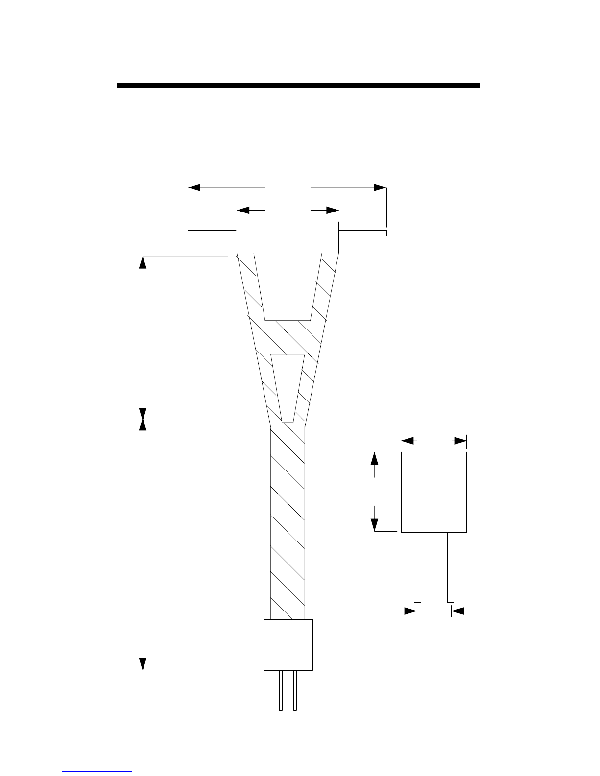
Shaft dimensions
The following are the dimensions of a fully extended
shaft. It is possible to reduce the length of the meter by
2” (5cm) by adjusting the lower half of the shaft.
14”
4”
Meter
16”
20”
3.0”
3.1”
1.3”
4
Page 5
Computer Interface/
Changing Batteries
Software Installation
Insert the CD for Field Scout software into your PC’s disk
drive. If auto-start is not enabled on your computer, select
Run from the Start menu and type D:\Setup.exe
(Substitute the appropriate drive letter for your CD drive).
Click OK and follow the instructions on the screen.
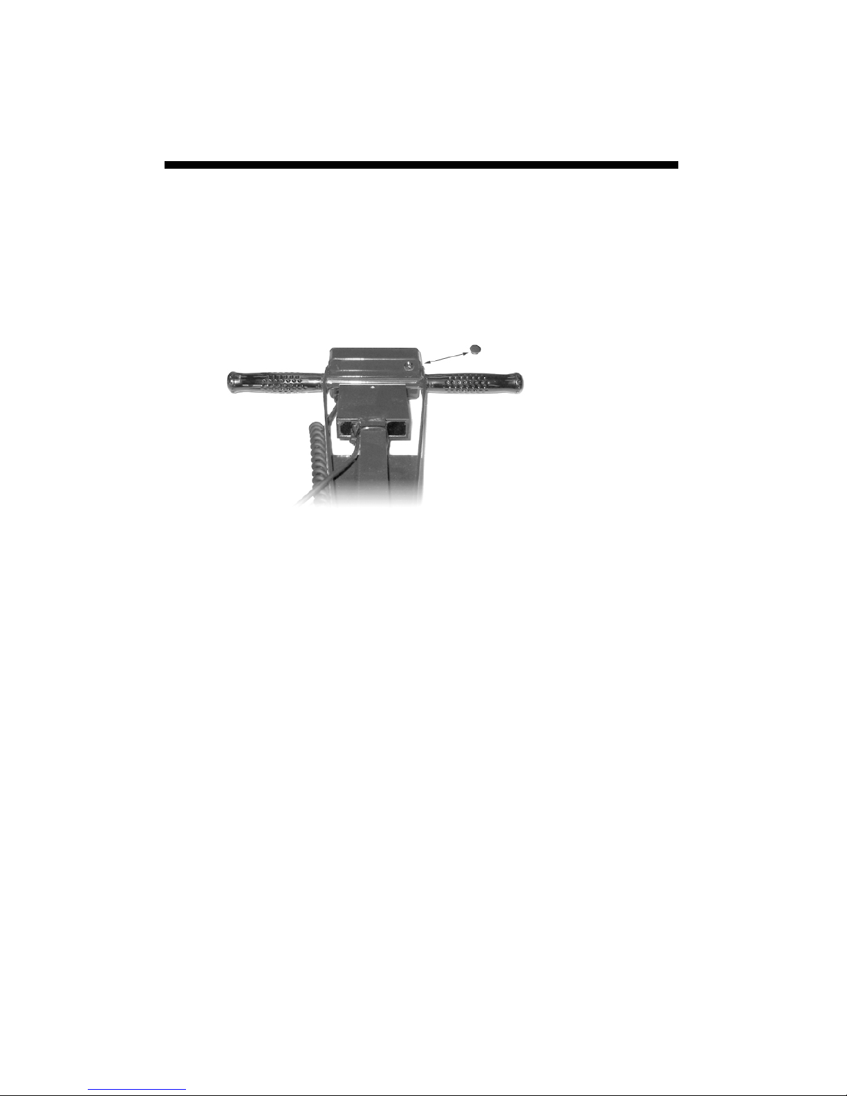
TDR 300
data port
The data port on the underside of the TDR 300 meter
(shown above) can be accessed by removing the plastic
screw. It is through this port that the meter is connected
to either a PC or to a GPS unit. The meter must be turned
off before attempting communication with the software.
Connecting to a PC
The Field Scout software comes with a gray PC interface
cable. This cable connects to the 9-pin serial port of your
computer and to the meter’s computer port. The meter’s
configuration can be modified by clicking on the Meter
Settings button (see Meter Settings, p. 16). The Com
Port, Meter Type, Download, Clear Memory and Me-
ter Settings buttons are explained in the Field Scout Soft-
ware Toolbar section (p. 14).
Changing the batteries
The battery compartment is accessed by removing the meter’s face plate. The meter is powered by AAA batteries.
When installing new batteries, note whether the batteries immediately feel hot to the touch. The battery
has been short-circuited and should be replaced.
5
Page 6
Identifying the
Correct Com Port
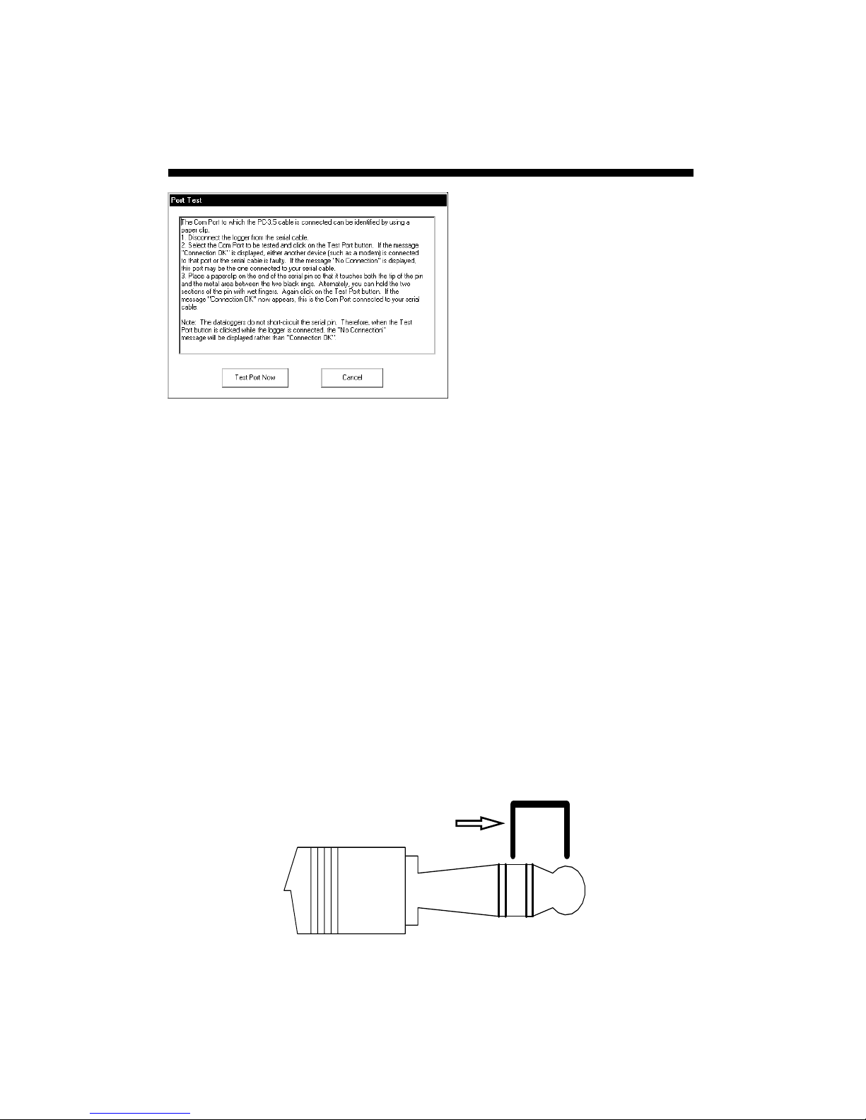
The computer
Communications Port to
which the PC-3.5 serial
cable is connected can be
identified by using a
paper clip.
1. Disconnect the serial
cable from the meter.
2. To bring up the Port Selection screen, click on the
Com Port Button, select the com port to be tested and
click the Port Test button. Click the Test Port Now
button. If the message “Connection OK” is displayed,
another device (such as a modem) is probably connected
to that port. If the message “No Connection” is displayed,
this port may be the one connected to your serial cable and
you can proceed to the next step.
3. Place a paperclip on the end of the serial pin so that it
touches both the tip of the pin and the metal area between
the two black rings. Again click on the Test Port Now
button. If the message “Connection OK” now appears,
this is the com port connected to your serial cable.
paper clip
or wire
NOTE: The dataloggers do not short-circuit the serial pin.
Therefore, when the Test Port button is clicked while the
meter is connected, the “No Connection” message will be
displayed.
6
Page 7

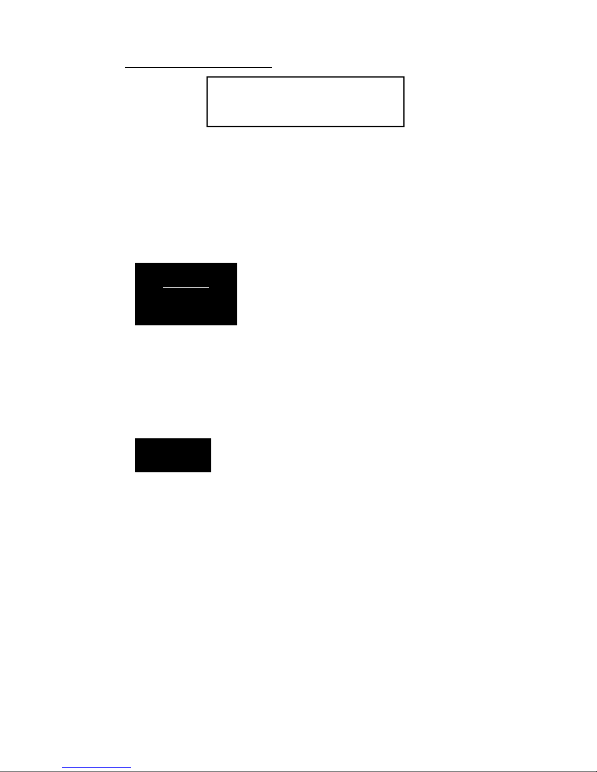
Meter Operation
ON
memory has been used and, if the logger was enabled in
the software, whether the GPS signal was found. If a GPS
signal is found, latitude and longitude data will be included in the data file. The screen will then display the
most recently used MODE screen.
Logger 75% Full
GPS=Yes DGPS=No
Sample meter power-up screens with datalogger
enabled: left screen indicates GPS signal was found.
The ON switch turns the meter/
datalogger on and off. When the meter is
turned on, it will display the battery
status for 3 seconds. For the next 3 seconds, it will display how much logger
Logger 75% Full
No GPS Found
If you are using GPS, but the meter doesn’t find the GPS
signal when powering up, the meter will not search for the
GPS signal when taking readings. Turn the meter off and
on so it can look for the GPS signal. Once the signal is
found, GPS information will be included in the data file
until the signal is lost or the GPS unit is disconnected
from the meter.
Note: If the data logger is disabled (see Meter Settings, p.
16), the meter will not seek the GPS signal when it is
powered up. It will, instead, proceed immediately to the
most recently used mode (see MODE button, p. 8) screen.
7
Page 8

MODE
Pressing the MODE button allows the
user to determine the type of measurement that will be taken or select the
length of rods connected to the probe.
Data Collection Modes
Available measurement options are volumetric water con-
MODE
tent (VWC) using the standard or high clay mode (see p.
22), up to two relative water content modes (see p. 24), or
measurement period (in microseconds). Relative water
content options will only appear if they are configured in
the software (see Meter Settings, p. 16). The period measurement is available for users interested in performing
soil-specific calibrations (see Appendix 2).
Note: There is not a high clay measurement calibration for
the 1.5” rods. The meter will display dashes if this mode/
rod length combination is selected.
Changing Rod Length
ROD=MED (4.7in)
HIT DEL To Chnge
In order to get accurate volumetric or relative water content (VWC or RWC) readings, the rod length setting must
be correct. In the VWC modes, the currently selected rod
length appears in the lower left corner of the LCD screen.
The options are Turf (1.5”), Short (3.0”), Medium (4.7”),
and L
LCD displays the rod length options screen. Pressing the
DELETE/CLR AVG button will allow you to toggle between the three choices.
ong (7.9”) rods. Press the MODE button until the
Rod Length Options Screen
8
Page 9
Meter Calibration Mode
CALIBRATION MODE
HIT READ To Cal
Meter Calibration Screen
This mode allows you to calibrate the meter. The calibration procedure is performed in air and distilled water
(see Meter Calibration, p. 10). Requires firmware v. 6.5
or greater.
Delete
Clr Avg
When the DELETE/CLR AVG
button is pressed and immediately
released, the last data point will be
taken out of the logger file and
removed from the running aver-
age. Pressing and holding this button will reset the running average but will not affect
data stored on the data logger.
Press the READ button to read the
probe and update the screen values.
READ
Data values, along with GPS or DGPS
information if applicable, are sent di-
rectly to the data logger. If the logger
searches for, but doesn’t find a GPS signal, an error
message will briefly appear in the lower right corner.
In this case, a data point will be stored without the GPS
data. The data point can be cleared from memory with
the DELETE/CLR AVG button (above).
When the data logger is full, the LCD will display the
message “Error: Memory Full”. To resume normal operation, the logger memory must be cleared using the
Clear Memory button in Field Scout software (see p.
15)
9
Page 10

Meter Calibration
The meter has internal calibrations for standard and
high-clay soil types. These calibrations will work for a
large number of soils. However, each meter will have a
small difference in how it responds to identical soil
conditions. This is due to sensor drift or variability in
the electronic components used during manufacturing.
Meters with firmware v. 6.5 or greater allow for adjustments to the meter calibration to account for these differences. Therefore, if two meters are giving slightly
different readings in the same soil, the output of the
meters can be standardized such that the meters can be
used interchangeably. The calibration procedure is as
follows:
1. Use the MODE button to put meter in Calibration
mode (see p. 8). Hit the READ button
2. Hold the meter so the rods are in the air. Press the
READ button and wait until the meter indicates it is
ready.
3. Immerse the rods completely in distilled or deionized water. The container should have a minimum
diameter of 3 inches. Press the READ button and wait
until the meter indicates it is ready.
The meter will then show that the calibration is complete for that specific rod length. If more than one rod
size is being used, a calibration operation must be done
for each one.
Note: This procedure is different than a soil-specific
calibration (Appendix 2, p. 28) where a unique calibration curve is generated.
10
Page 11

Taking Readings
- Remove one of the
hand screws from the
shaft. This will allow
you to unfold the shaft
to its full length. Return the screw to lock
the shaft in the extended position.
- Screw the rods into
the sockets at the bottom of the probe block.
- Turn on the meter and ensure that it is configured with
the correct rod length setting (see Changing Rod Length,
p. 8).
- Select the correct mode setting (see Data Collection
Modes, p. 8). This will bring you to one of the data collection screens. The TDR 300 can be set to one of two
VWC modes, Standard or High Clay.The Standard
mode will be appropriate for most mineral soils. The
High Clay mode will be more accurate for soils with
higher clay contents (>27%). In VWC mode, the top
line of the display shows the VWC mode and the water
content. The bottom line has probe setting and data file
information.
11
Page 12

STNDRD VWC%=35.1
PL=S N015 A=36.3
Sample Data Screen
PL: Probe Length (Turf,
Short, Medium, or Long rods)
N: Number of readings included in the Average
A: Average of all readings taken since meter was
turned on or DELETE/CLR AVG button was
pressed
Note, the internal calibrations are valid for a wide range of
mineral soils. However, for soils that are high in clay, organic matter or salt, the meter will give values that are
higher than the actual VWC. In this case, it is recommended that the meter be operated in relative water content
mode (see p. 24) or that a soil-specific calibration be developed (see Appendix 2).
The meter can also be set to give the raw reading if it is set
to Period mode. This mode is intended primarily for soilspecific calibrations.
- Push the rods into the soil. When taking a measurement, it
is important that the rods be fully inserted into the soil. If
not, part of the sampling volume will be composed of air
and the reading will be inaccurately low. For the same reason, the probe should be inserted with a steady, downward
pressure. If the rods are wiggled into the soil, air pockets
can be created adjacent to the rods that will result in low
readings. The probe should not be struck with a hammer or
other blunt instrument as this can cause damage to the internal electronics. Also, care should be taken to ensure the
rods are inserted as parallel to one another as possible. This
12
Page 13

will not have a large affect on the reading but will decrease the chances the rods will be bent or broken. Likewise, it is best to avoid areas with rocks or other material
that can cause the rods to deflect or bend. If the ground
is especially hard or compact, you can use a Pilot Hole
maker (item 6430PH) to make 1½” holes to aid in starting the insertion of the probe rods.
- Press the READ button to initiate the measurement sequence. The reading should appear almost instantaneously.
Note: The TDR rods are manufactured from type 303
stainless steel and are designed to bend if non-vertical
force is applied to them. This serves to protect the TDR
block electronics from potential damage that could be
caused by excessive force.
Occasional rod bending is normal, and can be expected
during the course of sampling. Longer rods will be more
susceptible to bending than shorter rods. If bending occurs, rods should simply be bent back to parallel position,
perpendicular to the TDR block. Measurements will
continue to be accurate provided that rods are reasonably
close to parallel.
If care is not taken to reposition rods to a parallel position, subsequent pressure on the rods will accentuate the
bending and may cause the rods to break. Rods should
be considered maintenance items that may need to be replaced over time, depending upon the nature and frequency of sampling.
13
Page 14

Field Scout
software Toolbar
Com Port
The gray software cable connects the meter to the computer
data port. Select the Com Port
that is assigned to the computer
data port. See Identifying the
Correct Com Port (p. 6) for instructions on how to determine
which port to select.
Meter Type
Select the TDR option from the
list of available Field Scout meters.
14
Page 15

Download
To download data from the internal data logger, turn the
meter off and connect the gray serial cable to the RS-232
port on the underside of the meter. Click the Download
button on the main software screen. In the Save Data As
screen, give the file a descriptive name and select the location where it will be saved.
When the file has been saved, the software will give you
the option of immediately viewing the file. The data file
is stored as a comma-delimited text file and may be
viewed in text editor or spreadsheet software.
Clear Memory
Data is not automatically removed from the logger memory after a download. The Clear Memory button clears
all data from the logger memory.
Meter Settings
Click this button to configure the meter and data logger.
Refer to “Meter Settings” (p. 16) for more details.
15
Page 16

Meter Settings
The Meter Settings screen in the Field Scout software
is used to configure the meter and data logger for your
specific application. The fields are described below.
Meter Name: The name given the meter will be the
title on the first line of the downloaded text file.
Logger Settings: The data logger is enabled and disabled by checking the first box. If the data logger is
enabled, it will search for a GPS signal when the meter
is turned on. If a signal is found, position data will be
stored along with the soil moisture data. If no GPS signal is available when the logger is turned on, the logger
will no longer look for one when measuring and recording soil moisture data. If the second box is
checked, the logger will store the GPS value only if it
has been differentially corrected. In general, this option should remain unchecked. If the differential cor-
16
Page 17

rection is not found, only the soil moisture value will be
stored in the data file. A time-zone correction should be
entered in the third box.
Units: When operating the meter in Relative Water Content mode, the LCD can display the rod length options in
English or metric units. The meter will calculate and display the water deficit (see Relative Water Content p. 24)
in the same unit system.
Relative Water Content Set Points: Up to 2 Relative
Water Content (see p. 24) modes can be programmed into
the meter by entering the wet and dry set points into the
appropriate boxes. From the dropdown menus near the
bottom of the screen, select which VWC calibration
(Standard or High Clay) should be used for each RWC
mode. Each of these modes can be given a descriptive
name of 5 characters. These names can be used to identify a certain field or soil type.
Finally, for an RWC mode to be available, it must be enabled by checking the Enable Display box. If this box is
not checked, that RWC mode will not appear on the LCD
during meter operation.
17
Page 18

Connecting to a
GPS Unit
The data logger function must be enabled using the Field
Scout software in order to record a GPS signal (see Meter
Settings p. 16).
The GPS unit must be plugged into the TDR 300 meter
and running when the meter is first turned on. If a GPS
signal is found at startup, the logger will search for a GPS
signal for every reading. If no GPS signal is found when
the meter is first turned on, the meter will not search for
one when taking readings, thereby saving time when taking readings. In this case the LCD will display the No
GPS Found message.
If the GPS signal is found while taking geo-referenced
readings, the LCD will briefly display the message,
“Reading GPS ..” before displaying the measurement. If
the GPS signal is lost during a series of readings, or if the
specified differential correction is not found, the LCD will
read “Reading GPS .. ERR” before returning to measurement mode. In this case, the data will be recorded without
latitude and longitude. During subsequent readings, the
meter will again search for a GPS.
GPS Setting
Your GPS unit must be set for NMEA 0183 input/output
messages. If the meter has trouble receiving the GPS signal, check that it has the following settings:
Data bits: 8 Stop bits: 1
Baud rate: 4800 bps Parity: None
Timing: 1 second GGA data string
18
Page 19

Cable Connections
A GPS/DGPS cable (item # 2950CV5) is required to connect the TDR 300 meter to a GPS unit. This cable has a
9-pin male connection and a stereo pin that connects to the
meter’s data port. You will also need a cable that allows
the GPS unit to connect to a 9-pin male serial port. If this
cable doesn’t come standard with your GPS unit, it should
be available from the manufacturer. This cable is generally used to upload information from a computer to the
GPS unit. These components should be connected as
shown in the figure below.
TDR
300
Meter
Spectrum
GPS/DGPS
Cable
GPS computer
interface cable
Connecting the TDR 300 meter to a GPS unit
GPS
Unit
19
Page 20

Data Files
Sample data showing results of data collected with and
without GPS activated. Note: GPS signal not found
when recording data in lines 17 through 26.
The data is stored in comma-delimited text files. These
files can be opened with text-editing software (e.g. Microsoft Word) or spreadsheet software (e.g. Excel).
The first two lines of the data file give the logger’s name
and serial number. The third line indicates that latitude
and longitude are referenced to the 1984 World Geodetic
Survey datum. The fourth line shows the column headings for the rest of the data file.
Logging sessions are started and completed by turning the
meter on and off. The start of a logging session is indicated by the data line “Logger Started.” If a GPS signal
was found at the start of a logger session, a time stamp is
included on the “Logger Started” line.
20
Page 21

The data is separated into 6 fields: Latitude and Longitude
(blank if a GPS unit was not connected), sample number,
value, measurement type, and rod length. The
“measurement type” data field indicates whether the reading is volumetric water content, relative water content or
measurement period. For volumetric water content data,
the calibration equation (Standard or High Clay) for that
data point will also be included in measurement type.
21
Page 22

Volumetric Water
Content
Measurements
Volumetric Water Content (VWC)
The soil can be thought of as being composed of soil,
water and air. The volumetric water content (VWC) is the
ratio of the volume of water in a given volume of soil to
the total soil volume. This can be expressed as either a
decimal or a percent. Three soil moisture levels of
importance can be defined as follows:
Saturation: All soil pores are filled with water. The VWC
will equal the percent pore space of the soil.
Field Capacity: The condition that exists after a saturated
soil is allowed to drain to a point where the pull of gravity
is no longer able to remove any additional water.
Permanent Wilting Point: The highest moisture content at
which a plant can no longer extract water from the soil.
Additionally, we can define Plant Available Water as the
amount of water between Permanent Wilting Point and
Field Capacity. One rule of thumb is that irrigation should
be initiated when half the Plant Available Water has been
depleted.
Time Domain Reflectometry (TDR)
The underlying principal of TDR involves measuring the
travel time of an electromagnetic wave along a
waveguide. The speed of the wave in soil is dependent on
the bulk dielectric permittivity (ε) of the soil matrix. The
fact that water (ε = 80) has a much greater dielectric con-
22
Page 23

stant than air (ε = 1) or soil solids (ε = 3-7) is exploited to
determine the VWC of the soil. The VWC measured by
TDR is an average over the length of the waveguide.
Electronics in the TDR 300 generate and sense the return
of a high energy signal that travels down and back,
through the soil, along the waveguide composed of the
two replaceable, stainless steel rods. The sampling volume is an elliptical cylinder that extends approximately 3
cm out from the rods. The high frequency signal information is then converted to volumetric water content. High
amounts of clay or high electrical conductivity
(EC>2 dS/m) will attenuate the high-frequency signal and
affect the reading displayed by the meter. Very high organic matter content will similarly affect the VWC reading.
23
Page 24

Relative water
Content Mode
RWC=25.5 D=3.17in
A=23.4 N=06 Asnte
In addition to displaying volumetric water content (VWC), the
meter can also display the relative water content (RWC) and
Water Deficit (see MODE button, p. 8). RWC is an index
value calculated with respect to upper (wet) and lower (dry)
VWC set points. The set points are configured with the software (refer to Meter Settings, p. 16). An RWC of 0 indicates
the soil is at the dry set point while an RWC of 100 indicates
the soil has reached the wet set point. (Example: Assume the
dry set point is VWC=25% and the wet set point is
VWC=40%. If the meter measured a VWC of 35%, this
would translate to a RWC of 67 because 35% is 2/3 between
25% and 40%.) If the soil’s volumetric water content is outside the range of the set points, it is possible to get a negative
RWC or an RWC greater than 100.
If the volumetric water contents for field capacity and permanent wilting point are the wet and dry set points respectively,
the RWC value will be equivalent to Plant Available Water
(PAW). A general rule of thumb is to recommend irrigation
when the soil has reached 50% of the PAW.
Also included on the first line is the Water Deficit. The Water
Deficit is the amount of rain or irrigation water necessary to
raise the soil water content to the wet set point. This calculation applies to a soil depth equal to the probe rod length. The
water deficit can be extrapolated further into the profile if the
porosity and water-holding characteristics are similar to the
volume of soil sampled by the probe.
24
Page 25

The second line of the LCD gives the Average (A) of all
readings taken, the Number (N) of readings taken and the
5-symbol name given to this soil type in the Meter Settings screen (see p. 16).
25
Page 26

Specifications
Measurement
Units
Resolution
Accuracy
Range
Power
Logger Capacity
Display
Percent volumetric water content
0.1%
±3.0% volumetric water content
with electrical conductivity < 2 dS m
–1
0% to saturation (Saturation is typically
around 50% volumetric water.)
4 AAA alkaline batteries
Approximately 12 month life
2700 readings without GPS, 1250 readings with GPS/DGPS
16 character, 2 line LCD
Weight
Probe Head
Dimensions
Rod Dimensions
3 lbs. (1.4 kg)
3.1” x 3” x 1”
(7.8cm x 7.5cm x 2.5cm)
Length : 1.5” (3.8cm), 3” (7.6cm),
4.7” (12cm) or 7.9” (20cm)
Diameter: 0.2” (0.5cm)
Spacing: 1.3” (3.3cm)
The internal data logger and RS-232 port are compatible
with GPS/DGPS. The data logger’s LCD screen will
display the data in one of three modes (see MODE button
p. 8):
1. Volumetric water content - in Standard or High Clay
mode
2. Relative water content - up to 2 RWC modes can be
established
3.
Measurement period - in microseconds
26
Page 27

Appendix 1
Time zone corrections
Time Zone
Correction
0 Dublin, Lisbon, London
3 Rio de Janeiro, Montevideo
4 Asuncion
5 Atlanta, Indianapolis, New York, Ottawa, Bogota,
6 Guatemala City, Houston, New Orleans, Chicago,
7 Phoenix, Denver, Edmonton
8 San Francisco, Los Angeles, Vancouver
9 Anchorage
10 Honolulu
11 Wellington
City
Montreal, Toronto
Mexico City, Winnipeg
13 Adelaide, Melbourne, Sydney
14 Vladivostok, Brisbane
15 Seoul, Tokyo
16 Beijing, Hong Kong, Manila, Singapore, Taipei
17 Hanoi, Jakarta, Vientiane
18 Calcutta, New Delhi
19 Kabul, Islamabad
20 Tehran, Abu Dhabi, Dubai
21 Moscow, Nairobi, Kampala, Riyadh
22 Ankara, Athens, Helsinki, Istanbul, Cairo,
Johannesburg, Harare
23 Amsterdam, Barcelona, Berlin, Geneva, Paris,
Prague, Rome, Brussels, Madrid, Stockholm,
Warsaw, Lagos
27
Page 28

Appendix 2
Soil-Specific
Calibration
For maximum accuracy, you
may choose to perform a
soil-specific calibration
rather than use either of the internal (Standard or High
Clay) soil calibrations coded into the TDR 300’s firmware. In these cases, an independent soil moisture content
measurement is required. A relation can then be developed that relates the meter’s period reading (see MODE
button, p. 8) to actual volumetric water content (VWC).
This is most easily accomplished by doing a regression of
one set of data against another.
VWC data can be obtained with a device such as a neutron
probe, by measuring the weight of a saturated soil column
of known volume as it is gradually dried, or by gradually
wetting a known volume soil with the addition of known
increments of water. In most cases, however, the calibra-
Period = 0950 uS
N015
tion will be done with gravimetric sampling. This procedure is briefly described below.
In the field, establish a number of sites to sample. Each
site should be wetted to a different soil moisture content
by adding varying amounts of water. At each site a Field
Scout TDR reading is taken followed by the extraction of
a known volume of soil. Ideally, this would be an undisturbed soil core. The wet weight of this soil must be determined. If the soil cannot be weighed immediately, it
should be stored in a plastic bag to reduce evaporation.
o
The soil is then oven-dried (105
mon requirement) and weighed again. The volumetric
water content is calculated as follows:
28
C for 48 hours is a com-
Page 29

VWC = 100*(M
wet
- M
)/(ρw*V
dry
tot
)
Where:
M
wet, Mdry
= total soil volume (ml)
V
tot
ρ
= density of water (1g/ml)
w
= mass (g) of wet and dry soil respectively
An alternate, but equivalent, calculation can be obtained
from the gravimetric water content and soil bulk density.
VWC = GWC *(ρ
b/ρw
)
Where GWC is the gravimetric water content and ρb is the
bulk density:
GWC = 100*(M
ρ
= M
b
dry/Vtot
wet
- M
dry
)/M
dry
The final step is to plot the calculated the measured period
values with the readings obtained from Field Scout TDR
meter. Regression analysis can then be performed on this
data to develop an equation to convert from period to
VWC.
29
Page 30

Appendix 3
Troubleshooting
1. Unable to bring up the Meter Settings screen.
Generally, this indicates that the PC is not able to communicate
with the meter. Check the following:
- The interface cable is securely connected to both the PC and
the meter
- The meter has fresh batteries
- The meter is off
- The correct COM port is selected (see p. 6)
- The Meter Type is set to the TDR family (see p. 14)
2. I am getting the “VWC%=ERR!” message.
This message appears for two reasons.
1. If the meter is set to read 1.5” (TURF) rods while in HiClay
mode. There is no high clay calibration for the rod length option. Change the rod length or switch to Standard calibration
mode.
2. The probe block is damaged. Meter must be returned for
repair. Contact Spectrum Technologies or your distributor to
obtain a Return Goods Authorization (RGA) number.
3. I am getting VWC values near 0% for all measurements,
even in very wet soil.
Most likely a circuit component in the display is damaged and
must be repaired. Contact Spectrum Technologies or your distributor to obtain a Return Goods Authorization (RGA) number.
4. When turning the meter on, it indicated it had found the
GPS signal. However, when taking readings I get a GPS
error message.
This can happen if the meter is set to only accept GPS readings
that have been differentially corrected. In general, this is not
necessary. On the Meter Settings screen (p. 16), uncheck the
second box in the Logger Settings section.
30
Page 31

5. The meter is not logging any data.
The meter is shipped with the data logger disabled. It must be
enabled in the Meter Settings screen (p. 16).
6. My Average reading suddenly went to 0%.
The average is only calculated for a maximum of 65 readings.
If additional readings are taken, the LCD will display a value of
0% for the average. Press and hold the DELETE/CLR AVG
button (p. 9) to return to normal operating mode.
7. My LCD is stuck at N = 250.
250 is the maximum number the LCD will display. At this
point, additional water content readings can be made, but the
index number (N value) will stay at 250. Press and hold the
DELETE/CLR AVG button (p. 9) to return to normal operating
mode.
8. I’m getting a “Memory Full” message.
The meter must be connected to Field Scout software to clear
the memory (see p. 15).
Warranty
This product is warranted to be free from defects in material or
workmanship for one year from the date of purchase. During
the warranty period Spectrum will, at its option, either repair or
replace products that prove to be defective. This warranty does
not cover damage due to improper installation or use, lightning,
negligence, accident, or unauthorized modifications, or to incidental or consequential damages beyond the Spectrum product. Before returning a failed unit, you must obtain a Returned
Materials Authorization (RMA) from Spectrum. Spectrum is not
responsible for any package that is returned without a valid
RMA number or for the loss of the package by any shipping
company.
31
Page 32

DECLARATION OF CONFORMITY
Spectrum Technologies, Inc.
3600 Thayer Court
Aurora, IL 60504 USA
Model Numbers: 6430FS
Description: Portable Soil Moisture Probe
Type: Electrical Equipment for Measurement, Control, and Laboratory
Use
Directive: 2004/108/EC
Standards: EN 61326-1:2006
EN 61000-4-2:1995, including A1:1998 and A2:2001
EN 61000-4-3:2002
As a consequence of the meter’s measurement principle, radio
frequencies less than 950 MHz can affect the meter’s readings. Operating the
meter in areas where such transmissions are present should be avoided.
EN 55011:2007
Douglas L. Kieffer, Soil/Water Products Manager March 18, 2009
 Loading...