

Page 1
Direct Soil
EC Meter
PRODUCT MANUAL
Item #’s
2265FS, 2265FSTP
®
Page 2

CONTENTS
Introduction 3
EC Probe 4
Probe Calibration 6
Meter Configuration 8
Direct Soil EC Readings 10
SME Measurement 11
Liquid Measurement/Other Features 12
Maintenance/Battery Replacement 13
Probe/Tip Replacement 14
Checking Probe Connection 16
Specifications 17
Appendices
1. Preferred EC Values for Selected Plants 18
2. Interpreting EC Readings From Turf Grass 20
3. Classification of Irrigation Water 22
4. Greenhouse Media 23
5. Diagnostic Messages 25
6. Celsius to Fahrenheit Conversion Chart 26
Warranty 27
This manual will familiarize you with the features and
operation of your Field Scout Soil & Water EC Meter.
Please read this manual thoroughly before using
your meter. For customer support or to place an
order call Spectrum Technologies, Inc.
800-248-8873 or (815) 436-4440
between 7:30 am and 5:30 PM CST
FAX at 815-436-4460
info@specmeters.com.
www.specmeters.com
Spectrum Technologies, Inc.
3600 Thayer Court
Aurora, IL 60504
2
Page 3

Introduction
Congratulations on the purchase of your FieldScout
Direct Soil EC Meter. This instrument has been specifically designed for direct measurement of salts in
soil media as well as water or nutrient solutions. This
manual describes how to use your meter and keep it
working accurately for many years. Please read it
thoroughly to get effective performance from your meter.
The salinity of the soil solution, irrigation water or fertilizer solution is an important parameter affecting the
root zone environment. Any of these factors can have
a significant effect on plant growth and physiology.
The easiest way to monitor salinity is by measuring the
electrical conductivity (EC). EC is strongly correlated
to the salinity of the soil solution. EC measurement is
also affected by temperature and, to a lesser degree,
by soil moisture content.
Use this portable EC meter and probe to measure salinity in greenhouse soil media right on the spot without tedious soil sampling and preparation. Greenhouse production managers can compare readings
from plant to plant and fine-tune their fertility program
because measurements can be made directly in a plug
tray cell without cannibalizing the seedlings. Turf
managers can monitor for high salt levels on golf
course greens and determine when to flush (leach)
salts before turf quality declines.
The meter comes with the Field Scout Soil/Water EC
probe. This single, stainless steel probe has a specially designed conical tip. It can measure liquid EC
(water or nutrient solutions) or in-situ soil salinity. The
probe automatically compensates for temperature.
3
Page 4
EC Probe
Electrical conductivity (EC) is an important
parameter in evaluating irrigation water and fertilizer
solutions. Crops can be damaged if irrigated with
water with a high conductivity. The quality of
irrigation water has been classified into 5 separate
categories (See Appendix 3, p. 22). EC is also an
indicator of the strength of fertilizer solutions. In
greenhouse applications and other situations
requiring frequent fertilization, EC should be checked
regularly to ensure the plants are getting sufficient
nutrients while avoiding the effects of salt toxicity.
See Appendix 1 (p. 18) for a list of preferred EC
values for some common plants. Typically, younger
plants will require lower EC than mature plants.
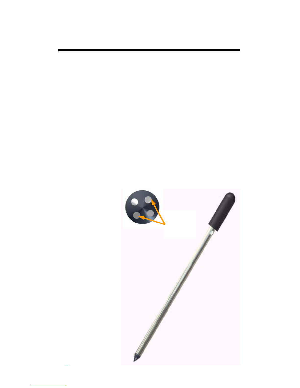
The stainless
steel soil EC
probe is
designed to be
inserted directly
into soil. The
sensing surface
is composed of 2
pairs of
electrodes on the
probe tip.
Additionally, the
probe is narrow
in diameter so it
can be used
effectively in plug
trays.
Sensor
Electrode
Pair
4
Page 5

Because EC readings are affected by moisture
content, it is important that soil moisture content
does not differ significantly between readings. An
easy way to achieve this condition is by taking
measurements approximately 30 to 60 minutes after
an irrigation. This should ensure the soil moisture
level has approximately reached field capacity.
The probe should be inserted in the root zone. The
measurement region is at the tip of the probe. For
turf, the root zone is approximately 2” - 4”. For
vegetables and small plants, this is about 8” - 12”.
Wait until the meter reading stabilizes before
withdrawing the probe. Taking several
measurements will allow a representative average to
be computed.
Important: Do not touch the sensor tip with your
fingers. The oils on the skin will affect the
probe’s measurement accuracy.
5
Page 6
Probe Calibration
The meter and probe are factory calibrated.
However, to ensure accuracy, the meter should be
calibrated at least once a month. The meter is
shipped with 2.76 mS/cm calibration solution. If you
are interested in calibrating to a concentration less
than 2 mS/cm, you will need to change the range
mode of the meter to AUTO (see Range Selection,
p. 9). Periodically, the calibration of the meter can
be checked by immersing the sensor in the
calibration solution. This solution should not be reused at a later date.
Calibration Procedure
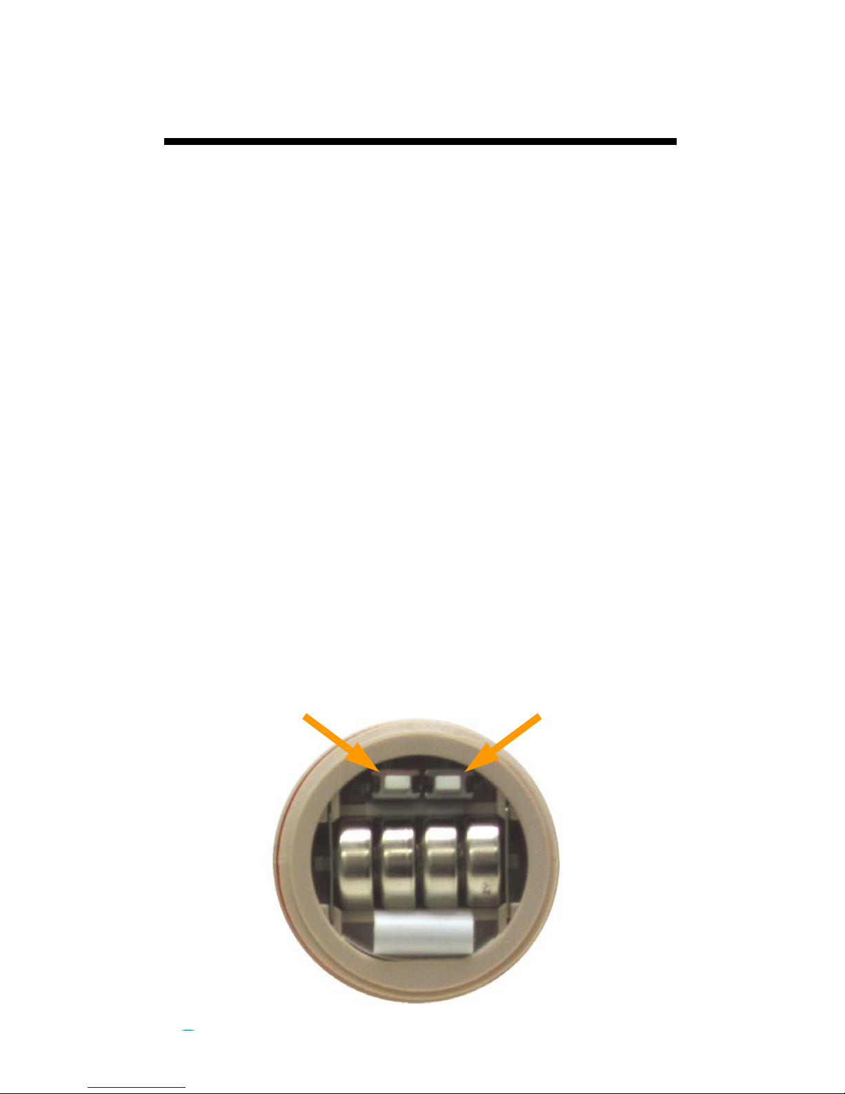
1.) Open battery compartment lid on the top of the
meter to access the small white Increment (INC) and
Decrement (DEC) calibration keys. When looking at
the battery compartment with the calibration keys
above the batteries, the DEC key will be to the left.
DEC
key
INC
key
6
Page 7

2.) If necessary, clean the probe with alcohol to
remove any residual oils. Rinse the electrode tip in
de-ionized (or distilled) water and then rinse it in the
calibration standard.
3.) Switch unit on with the ON/OFF key. Place
probe tip into a container of calibration standard.
Take care that the 4 exposed electrodes on the tip
are not touching the side or bottom of the container
holding the buffer solution. Wait for display to
stabilize (display value is unchanged and stable for 3
seconds).
4.) Pressing either calibration key will put the meter
into CALIBRATION mode. Press the INC or DEC
key to adjust the reading. If a key is held down, the
adjustment will happen more rapidly.
5.) When the EC of the calibration standard is
reached, release the keys for 3 seconds. The
temperature reading will briefly flash “CO”. The
Waterproof EC Tester accepts the calibration value
and returns to MEASUREMENT mode.
7
Page 8

Meter Configuration
The digital reader for the Field Scout EC meter is
shipped in Manual, 1-Point calibration, HI range
mode. In this mode, the EC units will always be
displayed as mS/cm. If you are working with less
concentrated solutions and want to calibrate or read
at a lower concentration, the range mode should be
changed to one of the other modes. This will allow
the meter to read in units of μS/cm.
Configuring the calibration mode
1. Switch off the display.
2. Press and hold the INC key (see p. 6 for diagram
of calibration keys) then simultaneously press the
ON/OFF button to switch on the display. The meter
will go into calibration selection mode.
3. The lower display shows "A.CAL" and the upper
display blinks the current choice (YES or NO). Press
either the INC or DEC key to select the NO option.
This disables the Automatic calibration mode and
configures the display for Manual calibration.
4. Press the HOLD/ENTER button to confirm the
selection. The display shows "CO".
5. After 1 second, the lower display will show "1.Pnt"
and the upper display blinks the current choice (YES
or NO). Press either the INC or DEC key to select
the YES option. This enables the 1-Point calibration
option.
4. Press the HOLD/ENTER button to confirm the
selection. The display shows "CO" and, after a few
seconds, goes to measurement mode.
8
Page 9

Range selection
1. Switch off the display.
2. Press and hold the oC/oF button then press and
release the ON/OFF button to switch on the display.
Release the oC/oF button. The meter will go into
Range selection mode and the lower display will
show the current choice. The options are "AUTO",
"PU", "LO", and "HI". See table 1 for a description of
each range.
3. Press the HOLD/ENTER button to select the
desired option. If the HOLD/ENTER button is not
pressed quickly after the oC/oF button is released,
the meter will transition to measurement mode.
Return to step 1 and repeat.
Abbreviation EC Range
PU 0 to 200.0 μS/cm
LO 0 to 2000 μS/cm
HI 0 to 20.00 mS/cm
AUTO Automatic
Table 1. Definition of the 4 EC range modes that can be
set on the meter. The mode will be displayed briefly
during the meter power-up sequence.
9
Page 10

Direct Soil EC Readings
Greenhouse Soils
The stainless steel probe of the Field Scout Soil &
Water EC Meter can be inserted directly into the soil.
By taking measurements at different soil depths, you
can determine where the fertilizer is concentrated in
the soil. Be aware that the soil moisture content will
significantly influence the measured EC value. To
ensure accurate measurement, it is recommended
that in-situ readings be taken when soil moisture is
close to field capacity or saturation. The probe tip
(sensor) must be held still in the soil to achieve a
stable measurement. Soil EC measurements made
with soils at field capacity or saturation will have
readings 10-15% more than SME measurements
due to a lesser amount of water in the soil.
Soil EC measurements should be made 30-60
minutes after irrigation.
Procedure
- Press On/Off button to power up the meter.
- Insert the probe tip 1 inch below soil surface.
- Wait for reading to stabilize (stable for 3 seconds)
[Automatic Temperature Compensation (ATC)
will correct for temperature changes].
- Repeat at 1 inch increments in the pot.
Golf Course Greens
A similar procedure can be followed for golf course
greens following irrigation or deep-soaking rain
event. Probe to the depth of the turf root zone.
Measurements exceeding 0.7 mS/cm (approximately
equivalent to 2.7 mS/cm in a saturated paste extract)
will result in cool season turf grass stress. See
Appendix 2 (p. 20) for more details.
10
Page 11

SME Measurement
Saturated Media Extract (SME) Measurements
Growth media used in most greenhouse operations
is high in organic material and processed materials
and low in mineral soil. These materials are easier
to handle, are well aerated and have good moistureholding properties, but have limited ability to retain
nutrients. Therefore, tests developed for field soils do
not always yield meaningful results. Saturated
Media Extract (SME) analysis has been shown to
eliminate these problems. The samples should not
be dried, sieved or pulverized as this will affect the
growth medium properties and alter the results.
Traditionally, the soil solution from the saturated
medium is extracted by a vacuum pump. However,
the Field Scout Soil & Water EC Meter allows the
saturated sample to be tested directly.
Procedure
- Moisten the media sample with distilled water to
reach a consistent “saturated” moisture level.
When saturated, the media should glisten and
slide from the mixing spatula with little or no free
water.
- Wait 15 minutes and add more water if needed.
The sample should have the consistency of a
paste with slightly more water than if the media
was in a pot and fully irrigated.
- Press On/Off button to power up the meter.
- Insert the probe tip into the media and read the
results.
11
Page 12

Liquid measurement/
Other Features
Water (Liquid) Measurements
The Field Scout Soil & Water EC Meter can also
measure the EC of liquids. Simply dip the electrode
tip into the solution and wait for the reading to
stabilize (a stable reading occurs when the readout
has not changed for 3 seconds).
Other Features
Hold
Pressing the HOLD key will freeze the display.
Press HOLD again to release.
Temperature Units
Press the C/F key to toggle between displaying
temperature in Fahrenheit and Celsius.
Auto Ranging
If the meter’s range mode is set to AUTO (see Meter
Configuration, p. 8), the LCD will automatically
transition from mS/cm to μS/cm as the unit of
measure when the EC value gets smaller (about 2
mS/cm). They differ by a factor of 1000. For
example: 1 mS/cm = 1000 μS/cm.
12
Page 13

Maintenance/
Battery Replacement
Maintenance:
To improve performance and avoid transferring soil-
borne diseases, clean the sensor tip by rinsing in
alcohol for 5 - 10 minutes.
Replace all batteries if low battery indicator appears,
or if readings are faint or unstable.
Store the probe sensor dry.
Important: Do not touch the sensor tip with your
fingers. The oils on the skin will affect the
probe’s measurement accuracy.
Changing Batteries:
1.) Open battery compartment lid (located near the
LCD screen).
2.) Remove and replace the old batteries. Note po-
larity shown in battery compartment. When inserting
new batteries, take
batteries
care to place them
over the white removal
tab. This will make future battery removal
much easier.
3.) Recalibrate meter
after every battery
change.
Removal
tab
13
Page 14

Probe/Tip
Replacement
If the probe cannot be calibrated, or if it does not
hold the calibration for a reasonable amount of time,
the probe or tip must be replaced. Current versions
of the 24” T-handle probe come with a replaceable
tip (item 2266). With these probes, the cable and
shaft do not need to be replaced.
An “OR” reading on the LCD (see Appendix 5) may
indicate a failed probe or simply that the probe has
come unplugged from the meter. See Checking
Probe Connection (p. 16) before replacing the
probe or tip.
Replacing a tip (24” probes only)
The replaceable tip (left) is designed to thread
in and out of the end of the probe. A new tip
has two flat faces on opposite sides. This
allows the tip to be tightened onto the probe
with a pliers or 5/16” wrench.
I. Removing a direct-insert probe
The 8” probe and older 24” probes do not have a
replaceable tip. The replacement procedure is
outlined below.
1. Remove the black nut from the strain-relief
where the cable feeds into the meter.
2. Remove the tan nut on the cable end of the
meter.
3. Detach the probe cable plug from the socket in
the meter.
4. Remove the tan nut and large o-ring. For the 24”
probe, also remove the strain relief from the
larger plastic assembly.
14
Page 15

Meter Housing
Black nut
Tan nut
Strain relief
Larger plastic
assembly/O-ring
socket
Probe plug
II. Attaching a direct-insert probe
1. If you are connecting an 8” probe, slide the tan
nut over the probe and down the black cable.
Skip to step 4.
2. If you are connecting a 24” probe, remove the
strain relief from the larger plastic assembly.
3. Feed the cable and strain relief through tan nut
and re-connect the strain relief and the assembly.
4. Attach the probe plug to the socket in the meter
housing.
5. Push the assembly onto the meter housing so the
metal pegs on the assembly line up with the
notches on the inner diameter of the meter
opening. Be sure that the small o-ring sits at the
base of the large plastic assembly.
6. While holding the assembly in place hand-tighten
the nut to the strain relief
7. Connect and tighten the tan nut to the meter
housing.
15
Page 16

Checking Probe
Connection
If the meter is giving an out-of-range (OR) error
message, it may be that the probe has come
unplugged from the meter. The procedure for
checking this is outlined below.
1. Remove the black nut from the strain-relief
where the cable feeds into the meter.
2. Remove the tan nut on the cable end of the
meter.
3. Ensure that the probe cable plug is firmly
connected to the socket in the meter.
4. Push the assembly onto the meter housing so the
metal pegs on the assembly line up with the
notches on the inner diameter of the meter
opening. Be sure that the small o-ring sits at the
base of the large plastic assembly.
5. While holding the assembly in place hand-tighten
the nut to the strain relief.
6. Connect and tighten the tan nut to the meter
housing.
black nut
16
tan nut
Strain relief
Larger plastic
assembly/O-ring
Probe plug
Page 17

Specifications
Readout LCD digital display
EC Range 0.00 - 19.99 mS/cm
Temperature 0 - 55 oC (32 - 122 oF)
Range
Accuracy EC: ±1% Full Scale
Temperature: ±0.5
EC Resolution 0.01 mS/cm
Calibration 1-point, manual
o
C
calibration
Temperature Automatic from 0 to 50oC
Compensation
Power Four LR44 1.5V alkaline
batteries
Battery Life 150 hours
Auto Shutoff After 8.5 minutes
17
Page 18

Appendix 1
Preferred EC Values
for Selected Plants
Plant EC (mS/cm)
Asparagus 1.5 - 2.0
Watermelon 1.5 - 2.5
Carrot 1.5 - 2.0
Cabbage 2.0 - 3.0
Cucumber 2.0 - 3.0
Crysanthemum 1.5 - 2.5
Onion 1.5 - 2.0
Bean 2.0 - 2.5
Strawberry 2.0 - 2.5
Lettuce 1.0 - 1.5
Eggplant 2.5 - 3.0
Melon 1.5 - 2.5
Potato 2.0 - 3.0
Pepper 2.0 - 3.0
Pea 1.0 - 1.5
Tomato 2.5 - 5.0
Celery 2.0 - 2.5
Marrow 2.0 - 2.5
Recommended soil EC for selected vegetable crops.
Note: The values on this table refer to measurement
of a saturated media extract (SME).
18
Page 19

Recommended EC Value (mS/cm)
SME a 1 to 2 b Pour thru
Poinsettia during
weeks 2-12.
Pansies during
active growth.
Geraniumus during
active growth.
2.0 - 3.0 0.85 - 1.25 2.8 - 4.1
0.25 - 1.5 0.1 - 0.6 0.35 - 2.1
1.6 - 2.4 0.65 - 1.0 2.2 - 3.3
Comparison of substrate tests for various EC sampling methods. (Calvins, Whipker, and Fonteno,
North Carolina State University).
a
saturated media extract
b
1 part soil to 2 parts water
19
Page 20

Appendix 2
Interpreting EC Readings
From Turf Grass
When taking direct-insert EC readings in turf grass
with the Field Scout meter, it is often helpful to convert the measurement to the equivalent Saturated
Media Extract (SME) value. This conversion will
vary for different soils. For sandy soils, the expression:
SME = 2.7FS + 0.8
provides a good approximation. FS refers to the
reading taken by the Field Scout meter. This equation is the basis for table 1. Table 2 lists a variety of
grass species and the range of EC values (converted
to SME) they can tolerate.
FS SME FS SME FS SME
0.1 1.1 1.1 3.8 2.1 6.5
0.2 1.3 1.2 4.0 2.2 6.7
0.3 1.6 1.3 4.3 2.3 7.0
0.4 1.9 1.4 4.6 2.4 7.3
0.5 2.2 1.5 4.9 2.5 7.6
0.6 2.4 1.6 5.1 2.6 7.8
0.7 2.7 1.7 5.4 2.7 8.1
0.8 3.0 1.8 5.7 2.8 8.4
0.9 3.2 1.9 5.9 2.9 8.6
1.0 3.5 2.0 6.2 3.0 8.9
Table 1: Conversion from Field Scout direct readings
(FS) to equivalent Saturated Media Extract (SME)
values. (Reference 9:3. PACE Turfgrass Research
Institute. San Diego, CA)
20
Page 21

Sensitive
< 3 mS/cm
Annual
Bluegrass
Colonial
Bluegrass
Kentucky
Bluegrass
Rough
Bluegrass
Centipedegrass Bahiagrass
Moderately
Sensitive
3 - 6 mS/cm
Annual
Ryegrass
Chewings
Fescue
Creeping
Bentgrass
Hard Fescue Buffalograss
Moderately
Tolerant
6 - 10 mS/cm
Bent cv.
Seaside
Perennial
Ryegrass
Tall Fescue
Zoysiagrass
Tolerant
>10 mS/cm
Alkaligrass
Bermudagrass
Seashore
Paspalum
St. Augustine-
grass
Table 2. Relative tolerance of turfgrasses to soil salinity measured by the SME Method (“Salinity in
Turfgrass”, Harivandi M.A, Butler J.D., Lin W. 1992).
Note: The values on this table refer to measurement
of a saturated media extract (SME) . Use table 1 to
convert from direct-insert readings to SME.
21
Page 22

Appendix 3
Classification of
Irrigation Water
Excellent
Good
Permissible
Doubtful
Unsuitable
Categories of irrigation water quality based on
electrical conductivity. [Wilcox L.V. (1948) The
Quality of Water for Irrigation Use, USDA Technical Bulletin 962]
0.25 mS/cm < EC < 0.75 mS/cm
0.75 mS/cm < EC < 2.0 mS/cm
2.0 mS/cm < EC < 3.0 mS/cm
EC < 0.25 mS/cm
EC > 3.0 mS/cm
22
Page 23

Appendix 4
Greenhouse Media
Classification of Greenhouse Media
Comments SME a 1 to 2 b 1 to 5 c
Very low levels. Indicates
very low nutrient status.
Suitable range for seedlings
and salt sensitive plants.
Desirable range for most
established plants. Upper
range may reduce growth
of some sensitive plants.
Slightly higher than desirable. Loss of vigor in upper
range. OK for high nutrient
requiring plants.
Reduced growth and vigor.
Wilting and marginal leaf
burn.
Severe salt injury symptoms with crop.
Electrical Conductivity (mS/cm)
0 - .74 0 - .25 0 - .12
.75 - 1.99 .25 - .75 .12 - .35
2.00 - 3.49 .75 - 1.25 .35 - .65
3.50 - 5.00 1.25 - 1.75 .65 - .90
5.00 - 6.00 1.75 - 2.25 .90 - 1.10
6.00+ 2.25+ 1.10+
Soluble salt guidelines for greenhouse media using
various media to water ratios (Testing and Nutrition
Guideline, MSU Ag Facts Extension Bulletin E-1736,
September, 1983).
a
saturated media extract
b
1 part soil to 2 parts water
c
1 part soil to 5 parts water
23
Page 24

Interpreting EC Readings from Soilless Media
The FieldScout EC meter allows for quick and easy
readings of salinity in a greenhouse container. The
following equations give an approximation of how a
direct-insert reading relates to more conventional soil
sampling techniques. The FieldScout reading is
designated by the variable FS.
Pour-through Method (PT)
PT = 1.637 * FS + 0.556
1:2 Dilution (OTT)
OTT = 0.448 * FS - 0.13
Saturated Media Extract (SME)
SME = 1.178 * FS - 0.294
Source:
Scoggins, H. L., VanIersal, M.W. 2006. In Situ
Probes for Measurement of Electrical Conductivity of
Soilless Substrates: Effects of Temperature and
Substrate Moisture Content. HortScience. 41:210214
24
Page 25

Appendix 5
Diagnostic Messages
Low Battery Indicator
- Battery 100% full
- Battery 50% full
- Battery 25% full
- Replace battery soon
OR/UR (steady)
- Measured EC or temperature value exceeds
specified maximum or minimum value.
• Sensor electrodes have short circuited.
• Sensor probe tip may need to be replaced.
- Sensor is not connected properly (see Checking
Probe Connection p. 16).
OR/UR/ATC (blinking)
- Short or open circuit at the built-in temperature
sensor.
Er.0
- Temperature not within specified range.
Er.1
- EC not within specified range.
25
Page 26

Appendix 6
Celsius to Fahrenheit
Conversion Chart
The Field Scout Soil & Water EC Meter gives
temperature readings in Celsius. The conversion
from Celsius to Fahrenheit is calculated with the
following equation:
F = 9/5 * C + 32
This information is also contained in the following
table:
C F C F C F
0 32.0 15 59.0 30 86.0
1 33.8 16 60.8 31 87.8
2 35.6 17 62.6 32 89.6
3 37.4 18 64.4 33 91.4
4 39.2 19 66.2 34 93.2
5 41.0 20 68.0 35 95.0
6 42.8 21 69.8 36 96.8
7 44.6 22 71.6 37 98.6
8 46.4 23 73.4 38 100.4
9 48.2 24 75.2 39 102.2
10 50.0 25 77.0 40 104.0
11 51.8 26 78.8 41 105.8
12 53.6 27 80.6 42 107.6
13 55.4 28 82.4 43 109.4
14 57.2 29 84.2 44 111.2
26
Page 27

Warr anty
This product is warranted to be free from defects in material or
workmanship for one year from the date of purchase. During
the warranty period Spectrum will, at its option, either repair or
replace products that prove to be defective. This warranty does
not cover damage due to improper installation or use, lightning,
negligence, accident, or unauthorized modifications, or to incidental or consequential damages beyond the Spectrum product. Before returning a failed unit, you must obtain a Returned
Materials Authorization (RMA) from Spectrum. Spectrum is not
responsible for any package that is returned without a valid
RMA number or for the loss of the package by any shipping
company.
27
Page 28

This equipment has been manufactured for
Spectrum Technologies, Inc.
3600 Thayer Court
Aurora, IL 60504 USA
The Manufacturer’s DECLARATION OF CONFORMITY is on file at the above
address, and certifies conformity to the following:
Model Number: 2265FS/2265FSTP
Description: Electrical Conductivity Meter
Type: Electrical Equipment for Measurement, Control, and
Laboratory Use
Directive: 89/336/EEC
Standards: EN 50081-1 (EN 55022)
EN 50082-1
Douglas L. Kieffer,
Soil/Water Products Manager April 7, 2009
(800) 248-8873 or (815) 436-4440
E-Mail: info@specmeters.com
28
3600 Thayer Court
Aurora, IL 60504
Fax (815) 436-4460
www.specmeters.com
R 12/13
 Loading...