

Page 1

digitizerNETBOX
DN2.44x-xx
DN6.44x-xx
Ethernet/LXI remote high speed digitizer
with 14/16 bit resolution
Hardware Manual
Software Driver Manual
English version September 11, 2018
SPECTRUM INSTRUMENTATION GMBH · AHRENSFELDER WEG 13-17 · 22927 GROSSHANSDORF · GERMANY
PHONE: +49 (0)4102-6956-0 · FAX: +49 (0)4102-6956-66 · E-MAIL: info@spec.de · INTERNET: www.spectrum-instrumentation.com
Page 2

(c) SPECTRUM INSTRUMENTATION GMBH
AHRENSFELDER WEG 13-17, 22927 GROSSHANSDORF, GERMANY
SBench, digitizerNETBOX and generatorNETBOX are registered trademarks of Spectrum Instrumentation GmbH.
Microsoft, Visual C++, Visual Basic, Windows, Windows 98, Windows NT, Windows 2000, Windows XP, Windows Vista, Windows 7,
Windows 8, Windows 10 and Windows Server are trademarks/registered trademarks of Microsoft Corporation.
LabVIEW, DASYLab, Diadem and LabWindows/CVI are trademarks/registered trademarks of National Instruments Corporation.
MATLAB is a trademark/registered trademark of The Mathworks, Inc.
Delphi and C++Builder are trademarks or registered trademarks of Embarcadero Technologies, Inc.
Keysight VEE, VEE Pro and VEE OneLab are trademarks/registered trademarks of Keysight Technologies, Inc.
FlexPro is a registered trademark of Weisang GmbH & Co. KG.
PCIe, PCI Express, PCI-X and PCI-SIG are trademarks of PCI-SIG.
PICMG and CompactPCI are trademarks of the PCI Industrial Computation Manufacturers Group.
PXI is a trademark of the PXI Systems Alliance.
LXI is a registered trademark of the LXI Consortium.
IVI is a registered trademark of the IVI Foundation
Oracle and Java are registered trademarks of Oracle and/or its affiliates.
Intel and Intel Xeon are trademarks and/or registered trademarks of Intel Corporation.
AMD and Opteron are trademarks and/or registered trademarks of Advanced Micro Devices.
NVIDIA, CUDA, GeForce, Quadro and Tesla are trademarks and/or registered trademarks of NVIDIA Corporation.
Page 3

Introduction....................................................................................................................... 9
Preface ............................................................................................................................................................................... 9
General Information ............................................................................................................................................................. 9
digitizerNETBOX Overview ................................................................................................................................................... 9
Internal Digitizer Modules ................................................................................................................................................... 10
Differences between plain cards and digitizer modules inside the digitizerNETBOX .............................................................. 10
Overview of digitizer modules inside the DN2-44x and DN6-44x digitizerNETBOX ............................................................. 11
Different models of the DN2.44x series................................................................................................................................. 12
Additional options for DN2 products .................................................................................................................................... 12
19“ Rack Mount Kit ...................................................................................................................................................... 12
DC Power Supply ......................................................................................................................................................... 12
Different models of the DN6.44x series................................................................................................................................. 13
Additional options for DN6 products .................................................................................................................................... 13
19“ Rack Mount Kit ...................................................................................................................................................... 13
AC Cable Options ............................................................................................................................................................. 14
The Spectrum type plate ..................................................................................................................................................... 15
Hardware information......................................................................................................................................................... 16
Block diagram of digitizerNETBOX DN2.44x and DN6.44x: ............................................................................................ 16
Block diagram of a single internal digitizer module:.......................................................................................................... 16
DN2 / DN6 Technical Data .......................................................................................................................................... 17
RMS Noise Level (Zero Noise), typical figures .................................................................................................................. 21
Dynamic Parameters ..................................................................................................................................................... 21
Noise Floor Plots (open inputs) ....................................................................................................................................... 22
DN2 specific Technical Data.......................................................................................................................................... 23
DN6 specific Technical Data.......................................................................................................................................... 23
DN2 Order Information ...................................................................................................................................................... 24
DN6 Order Information ...................................................................................................................................................... 25
Hardware Installation ..................................................................................................... 26
Warnings.......................................................................................................................................................................... 26
ESD Precautions ........................................................................................................................................................... 26
Opening the Chassis..................................................................................................................................................... 26
Cooling Precautions...................................................................................................................................................... 26
Sources of noise ........................................................................................................................................................... 26
Installing 19“ rack mount option for DN2.............................................................................................................................. 27
Installing 19“ rack mount option for DN6.............................................................................................................................. 27
Setup of digitizerNETBOX/generatorNETBOX ....................................................................................................................... 28
Connections................................................................................................................................................................. 28
Front Panel DN2 .......................................................................................................................................................... 28
Front Panel DN6 .......................................................................................................................................................... 29
Ethernet Default Settings ................................................................................................................................................ 29
Detecting the digitizerNETBOX ............................................................................................................................................ 30
Discovery Function........................................................................................................................................................ 30
Finding the digitizerNETBOX/generatorNETBOX in the network......................................................................................... 30
Troubleshooting............................................................................................................................................................ 31
Software Driver Installation............................................................................................. 32
Needed Software for operating ........................................................................................................................................... 32
Location ............................................................................................................................................................................ 32
Linux................................................................................................................................................................................. 33
Overview .................................................................................................................................................................... 33
Standard Driver Installation............................................................................................................................................ 33
Standard Driver Update ................................................................................................................................................ 34
Compilation of kernel driver sources (option) ................................................................................................................... 34
Update of self compiled kernel driver .............................................................................................................................. 34
Library only ................................................................................................................................................................. 34
Control Center ............................................................................................................................................................. 35
3
Page 4

Software ......................................................................................................................... 36
Software Overview............................................................................................................................................................. 36
Card Control Center ........................................................................................................................................................... 36
Discovery of Remote Cards and digitizerNETBOX/generatorNETBOX products.................................................................... 37
Wake On LAN of digitizerNETBOX/generatorNETBOX .................................................................................................... 37
Netbox Monitor ........................................................................................................................................................... 38
Hardware information................................................................................................................................................... 38
Firmware information .................................................................................................................................................... 39
Software License information.......................................................................................................................................... 39
Driver information......................................................................................................................................................... 40
Installing and removing Demo cards ............................................................................................................................... 40
Feature upgrade........................................................................................................................................................... 40
Software License upgrade.............................................................................................................................................. 41
Performing card calibration ........................................................................................................................................... 41
Performing memory test ................................................................................................................................................. 41
Transfer speed test........................................................................................................................................................ 41
Debug logging for support cases .................................................................................................................................... 42
Device mapping........................................................................................................................................................... 42
Accessing the hardware with SBench 6................................................................................................................................. 42
C/C++ Driver Interface....................................................................................................................................................... 43
Header files ................................................................................................................................................................. 43
General Information on Windows 64 bit drivers............................................................................................................... 43
Microsoft Visual C++ 6.0, 2005 and newer 32 Bit........................................................................................................... 43
Microsoft Visual C++ 2005 and newer 64 Bit.................................................................................................................. 44
C++ Builder 32 Bit ....................................................................................................................................................... 44
Linux Gnu C/C++ 32/64 Bit ......................................................................................................................................... 44
C++ for .NET............................................................................................................................................................... 44
Other Windows C/C++ compilers 32 Bit ........................................................................................................................ 44
Other Windows C/C++ compilers 64 Bit ........................................................................................................................ 45
National Instruments LabWindows/CVI........................................................................................................................... 45
Driver functions .................................................................................................................................................................. 45
Delphi (Pascal) Programming Interface .................................................................................................................................. 50
Driver interface ............................................................................................................................................................ 50
Examples..................................................................................................................................................................... 51
Visual Basic Programming Interface and Examples ................................................................................................................. 52
Driver interface ............................................................................................................................................................ 52
Examples..................................................................................................................................................................... 53
.NET programming languages ............................................................................................................................................. 54
Library ........................................................................................................................................................................ 54
Declaration.................................................................................................................................................................. 54
Using C#..................................................................................................................................................................... 54
Using Managed C++/CLI.............................................................................................................................................. 55
Using VB.NET .............................................................................................................................................................. 55
Using J# ...................................................................................................................................................................... 55
Python Programming Interface and Examples......................................................................................................................... 56
Driver interface ............................................................................................................................................................ 56
Examples..................................................................................................................................................................... 57
Java Programming Interface and Examples............................................................................................................................ 58
Driver interface ............................................................................................................................................................ 58
Examples..................................................................................................................................................................... 58
LabVIEW driver and examples............................................................................................................................................. 59
MATLAB driver and examples.............................................................................................................................................. 59
Integrated Webserver...................................................................................................... 60
Home Screen ............................................................................................................................................................... 60
LAN Configuration ....................................................................................................................................................... 60
Status.......................................................................................................................................................................... 61
Security....................................................................................................................................................................... 61
Documentation ............................................................................................................................................................. 61
Firmware Update.......................................................................................................................................................... 62
Power ......................................................................................................................................................................... 62
Downloads .................................................................................................................................................................. 62
Logging....................................................................................................................................................................... 62
Access ........................................................................................................................................................................ 63
Embedded Server ......................................................................................................................................................... 63
Login/Logout ............................................................................................................................................................... 63
4
Page 5

IVI Driver......................................................................................................................... 64
About IVI........................................................................................................................................................................... 64
General Concept of the Spectrum IVI driver ........................................................................................................................... 64
Supported Spectrum Hardware ............................................................................................................................................ 65
Supported data acquisition card families:........................................................................................................................ 65
Supported digitizerNETBOX families............................................................................................................................... 65
Supported generatorNETBOX families............................................................................................................................. 65
IVI Compliance .................................................................................................................................................................. 65
Supported Operating Systems ........................................................................................................................................ 65
Supported Standard Driver Features................................................................................................................................ 66
IVIScope Supported Class Capabilities............................................................................................................................ 66
IVIDigitizer Supported Class Capabilities......................................................................................................................... 66
IVIFGen Supported Class Capabilities ............................................................................................................................. 67
Find more Information on IVI................................................................................................................................................ 67
General Information on IVI............................................................................................................................................. 67
IVI Getting Started Guides and Videos ............................................................................................................................ 67
Installation......................................................................................................................................................................... 67
Installer ....................................................................................................................................................................... 67
Shared Components ..................................................................................................................................................... 67
Installation Procedure .................................................................................................................................................... 67
Installation of the IVI driver package ............................................................................................................................... 68
Configuration Store ............................................................................................................................................................ 69
General Information...................................................................................................................................................... 69
Repeated Capabilities................................................................................................................................................... 69
Programming the Board .................................................................................................. 70
Overview .......................................................................................................................................................................... 70
Register tables ................................................................................................................................................................... 70
Programming examples....................................................................................................................................................... 70
Initialization....................................................................................................................................................................... 71
Initialization of Remote Products........................................................................................................................................... 71
Error handling.................................................................................................................................................................... 71
Gathering information from the card..................................................................................................................................... 72
Card type.................................................................................................................................................................... 72
Hardware and PCB version ........................................................................................................................................... 73
Reading currently used PXI slot No. (M4x only) ................................................................................................................ 73
Production date ............................................................................................................................................................ 73
Last calibration date (analog cards only) ......................................................................................................................... 73
Serial number .............................................................................................................................................................. 74
Maximum possible sampling rate ................................................................................................................................... 74
Installed memory .......................................................................................................................................................... 74
Installed features and options ......................................................................................................................................... 74
Miscellaneous Card Information ..................................................................................................................................... 75
Function type of the card ............................................................................................................................................... 75
Used type of driver ....................................................................................................................................................... 75
Reset................................................................................................................................................................................. 76
Gathering information from the digitizerNETBOX/generatorNETBOX ....................................................................................... 77
Analog Inputs.................................................................................................................. 78
Channel Selection .............................................................................................................................................................. 78
Important note on channels selection............................................................................................................................... 79
Setting up the inputs ........................................................................................................................................................... 79
Input Path .................................................................................................................................................................... 79
Input ranges................................................................................................................................................................. 79
Input offset................................................................................................................................................................... 81
Read out of input features .............................................................................................................................................. 82
Input termination........................................................................................................................................................... 82
Input coupling .............................................................................................................................................................. 83
AC/DC offset compensation .......................................................................................................................................... 83
Anti aliasing filter (Bandwidth limit)................................................................................................................................. 83
Automatic on-board calibration of the offset and gain settings............................................................................................ 83
5
Page 6

Acquisition modes ........................................................................................................... 85
Overview .......................................................................................................................................................................... 85
Setup of the mode ........................................................................................................................................................ 85
Commands........................................................................................................................................................................ 86
Card Status.................................................................................................................................................................. 87
Acquisition cards status overview ................................................................................................................................... 87
Generation card status overview .................................................................................................................................... 87
Data Transfer ............................................................................................................................................................... 87
Standard Single acquisition mode ........................................................................................................................................ 90
Card mode.................................................................................................................................................................. 90
Memory, Pre- and Posttrigger ......................................................................................................................................... 90
Example ...................................................................................................................................................................... 90
FIFO Single acquisition mode .............................................................................................................................................. 91
Card mode.................................................................................................................................................................. 91
Length and Pretrigger.................................................................................................................................................... 91
Difference to standard single acquisition mode................................................................................................................. 91
Example FIFO acquisition .............................................................................................................................................. 91
Limits of pre trigger, post trigger, memory size ....................................................................................................................... 92
Buffer handling .................................................................................................................................................................. 93
Data organization .............................................................................................................................................................. 96
Sample format ................................................................................................................................................................... 96
Converting ADC samples to voltage values ...................................................................................................................... 97
Applying correction factors when using special clock mode ............................................................................................... 97
Clock generation ............................................................................................................. 98
Overview .......................................................................................................................................................................... 98
Clock Mode Register..................................................................................................................................................... 98
The different clock modes .............................................................................................................................................. 98
Details on the different clock modes...................................................................................................................................... 99
Standard internal sampling clock (PLL)............................................................................................................................. 99
Minimum internal sampling rate ..................................................................................................................................... 99
Clock Setup Granularity and Divider (Special Clock Mode) ............................................................................................... 99
Using Quartz2 with PLL (optional, M4i cards only).......................................................................................................... 101
Oversampling ............................................................................................................................................................ 101
External clock (reference clock) .................................................................................................................................... 101
PXI Reference Clock (M4x cards only) ........................................................................................................................... 102
Trigger modes and appendant registers ........................................................................ 103
General Description.......................................................................................................................................................... 103
Trigger Engine Overview................................................................................................................................................... 103
Trigger masks .................................................................................................................................................................. 104
Trigger OR mask ........................................................................................................................................................ 104
Trigger AND mask...................................................................................................................................................... 105
Software trigger ............................................................................................................................................................... 106
Force- and Enable trigger .................................................................................................................................................. 107
Trigger delay ................................................................................................................................................................... 107
Main external window trigger (Ext0)................................................................................................................................... 108
Trigger Mode............................................................................................................................................................. 108
Trigger Input Termination............................................................................................................................................. 108
Trigger Input Coupling ................................................................................................................................................ 109
Secondary external level trigger (Ext1) ................................................................................................................................ 109
Trigger Mode............................................................................................................................................................. 109
Trigger level............................................................................................................................................................... 109
Detailed description of the external analog trigger modes ............................................................................................... 110
Channel Trigger ............................................................................................................................................................... 114
Overview of the channel trigger registers....................................................................................................................... 114
Channel trigger level................................................................................................................................................... 115
Detailed description of the channel trigger modes........................................................................................................... 117
Multi Purpose I/O Lines..................................................................................................................................................... 123
Programming the behavior........................................................................................................................................... 123
Using asynchronous I/O ............................................................................................................................................. 124
Special behavior of trigger output................................................................................................................................. 124
Mode Multiple Recording ............................................................................................... 125
Recording modes ............................................................................................................................................................. 125
Standard Mode.......................................................................................................................................................... 125
FIFO Mode ................................................................................................................................................................ 125
Limits of pre trigger, post trigger, memory size ..................................................................................................................... 126
Multiple Recording and Timestamps.............................................................................................................................. 127
Trigger Modes ................................................................................................................................................................. 127
Trigger Counter.......................................................................................................................................................... 127
Programming examples..................................................................................................................................................... 128
6
Page 7

Mode Gated Sampling................................................................................................... 129
Acquisition modes ............................................................................................................................................................ 129
Standard Mode.......................................................................................................................................................... 129
FIFO Mode ................................................................................................................................................................ 129
Limits of pre trigger, post trigger, memory size ..................................................................................................................... 130
Gated Sampling and Timestamps ................................................................................................................................. 130
Trigger............................................................................................................................................................................ 131
Detailed description of the external analog trigger modes ............................................................................................... 131
Channel triggers modes .............................................................................................................................................. 135
Programming examples..................................................................................................................................................... 140
Mode Boxcar Average (High-Resolution)........................................................................ 141
Overview ........................................................................................................................................................................ 141
General Information.................................................................................................................................................... 141
Principle of operation.................................................................................................................................................. 141
Simplified Block Diagram ............................................................................................................................................ 142
Setting up the Acquisition ............................................................................................................................................ 142
Recording modes ............................................................................................................................................................. 143
Standard Mode.......................................................................................................................................................... 143
FIFO Mode ................................................................................................................................................................ 143
Limits of pre trigger, post trigger, memory size ..................................................................................................................... 143
Trigger Modes ................................................................................................................................................................. 144
Output Data Format.......................................................................................................................................................... 144
Data organization ............................................................................................................................................................ 144
Programming examples..................................................................................................................................................... 145
Mode 8bit Storage (Low-Resolution) .............................................................................. 146
Overview ........................................................................................................................................................................ 146
Available acquisition modes .............................................................................................................................................. 146
Enabling hardware data conversion ................................................................................................................................... 146
Sample format ................................................................................................................................................................. 146
Limits of pre trigger, post trigger, memory size ..................................................................................................................... 147
Converting ADC samples to voltage values.......................................................................................................................... 147
Timestamps ................................................................................................................... 148
General information ......................................................................................................................................................... 148
Example for setting timestamp mode: ............................................................................................................................ 148
Timestamp modes............................................................................................................................................................. 149
Standard mode .......................................................................................................................................................... 149
StartReset mode.......................................................................................................................................................... 149
Refclock mode............................................................................................................................................................ 149
Reading out the timestamps ............................................................................................................................................... 150
General..................................................................................................................................................................... 150
Data Transfer using DMA ............................................................................................................................................ 151
Data Transfer using Polling .......................................................................................................................................... 153
Comparison of DMA and polling commands.................................................................................................................. 153
Data format ............................................................................................................................................................... 153
Combination of Memory Segmentation Options with Timestamps ........................................................................................... 155
Multiple Recording and Timestamps.............................................................................................................................. 155
Example Multiple Recording and Timestamps................................................................................................................. 155
ABA Mode and Timestamps......................................................................................................................................... 155
ABA mode (dual timebase) ............................................................................................ 157
General information ......................................................................................................................................................... 157
Standard Mode.......................................................................................................................................................... 157
FIFO Mode ................................................................................................................................................................ 158
Limits of pre trigger, post trigger, memory size ..................................................................................................................... 158
Example for setting ABA mode: .................................................................................................................................... 159
Reading out ABA data ...................................................................................................................................................... 159
General..................................................................................................................................................................... 159
Data Transfer using DMA ............................................................................................................................................ 160
Data Transfer using Polling .......................................................................................................................................... 162
Comparison of DMA and polling commands.................................................................................................................. 162
ABA Mode and Timestamps......................................................................................................................................... 163
7
Page 8

Option Star-Hub (M3i and M4i only) .............................................................................. 164
Star-Hub introduction ........................................................................................................................................................ 164
Star-Hub trigger engine ............................................................................................................................................... 164
Star-Hub clock engine ................................................................................................................................................. 164
Software Interface ............................................................................................................................................................ 164
Star-Hub Initialization.................................................................................................................................................. 164
Setup of Synchronization............................................................................................................................................. 166
Setup of Trigger ......................................................................................................................................................... 166
Run the synchronized cards ......................................................................................................................................... 167
SH-Direct: using the Star-Hub clock directly without synchronization.................................................................................. 168
Error Handling ........................................................................................................................................................... 168
Mode Block Average (Firmware Option) ........................................................................ 169
Overview ........................................................................................................................................................................ 169
General Information.................................................................................................................................................... 169
Principle of operation.................................................................................................................................................. 169
Simplified Block Diagram ............................................................................................................................................ 170
Setting up the Acquisition ............................................................................................................................................ 170
Recording modes ............................................................................................................................................................. 170
Standard Mode.......................................................................................................................................................... 170
FIFO Mode ................................................................................................................................................................ 171
Limits of pre trigger, post trigger, memory size ..................................................................................................................... 172
For cards with 12bit, 14bit and 16bit ADC resolution (firmware V14 and above): ............................................................. 172
For cards with 8bit ADC resolution, 32 bit data mode (firmware V14 and above): ............................................................. 172
For cards with 8bit ADC resolution, 16 bit data mode (firmware V14 and above): ............................................................. 172
Trigger Modes ................................................................................................................................................................. 172
Output Data Format.......................................................................................................................................................... 172
Data organization ............................................................................................................................................................ 173
Programming examples..................................................................................................................................................... 173
Mode Block Statistics (Firmware Option) ........................................................................ 175
Overview ........................................................................................................................................................................ 175
General Information.................................................................................................................................................... 175
Waveform Block Statistics............................................................................................................................................ 175
Simplified Block Diagram ............................................................................................................................................ 176
Setting up the Acquisition ............................................................................................................................................ 176
Recording modes ............................................................................................................................................................. 176
Standard Mode.......................................................................................................................................................... 176
FIFO Mode ................................................................................................................................................................ 177
Limits of pre trigger, post trigger, memory size ..................................................................................................................... 177
For cards with 12bit, 14bit and 16bit ADC resolution:.................................................................................................... 177
For cards with 8bit ADC resolution: .............................................................................................................................. 177
Trigger Modes ................................................................................................................................................................. 177
Information Set Format ...................................................................................................................................................... 178
Data organization ............................................................................................................................................................ 178
Programming examples..................................................................................................................................................... 179
Option Embedded Server............................................................................................... 180
Acessing the Embedded Server .......................................................................................................................................... 180
SSH Connection ......................................................................................................................................................... 180
Login ........................................................................................................................................................................ 180
Mounting network folders ............................................................................................................................................ 180
Access to NTP (Network Time Protocol) ......................................................................................................................... 180
Editors....................................................................................................................................................................... 181
Installing packages ..................................................................................................................................................... 181
Programming................................................................................................................................................................... 181
Accessing the cards .................................................................................................................................................... 181
Examples................................................................................................................................................................... 181
Autostart.................................................................................................................................................................... 181
LEDs.......................................................................................................................................................................... 182
Appendix ...................................................................................................................... 183
Error Codes..................................................................................................................................................................... 183
Spectrum Knowledge Base .......................................................................................................................................... 184
Temperature sensors ......................................................................................................................................................... 185
Temperature read-out registers ..................................................................................................................................... 185
Temperature hints ....................................................................................................................................................... 185
44xx temperatures and limits ....................................................................................................................................... 185
Details on M4i/M4x cards I/O lines .................................................................................................................................. 186
Multi Purpose I/O Lines............................................................................................................................................... 186
Interfacing with clock input .......................................................................................................................................... 186
Interfacing with clock output......................................................................................................................................... 186
8
Page 9
Introduction Preface
Introduction
Preface
This manual provides detailed information on the hardware features of your Spectrum instrument. This information includes technical data,
specifications, block diagrams and a connector description.
In addition, this guide takes you through the process of installing and recognizing your hardware and also describes the installation of the
delivered driver package for each operating system.
Finally this manual provides you with the complete software information of the hardware and the related driver. The reader of this manual
will be able to control the instrument from any PC system with one of the supported operating systems and one of the supported operating
software packages.
Please note that this manual provides no description for specific driver parts such as those for IVI, LabVIEW or MATLAB. These drivers manuals
are available on CD or on the Spectrum website.
For any new information on the board as well as new available options or memory upgrades please contact our website
www.spectrum-instrumentation.com. You will also find the current driver package with the latest bug fixes and new features on our site.
Please read this manual carefully before you install any hardware or software. Spectrum is not responsible
for any hardware failures resulting from incorrect usage.
General Information
The DN2.44x series allows recording of up to 8 channels and the DN6.44x series even up to 24 channels in the high speed high resolution
segment. Due to the proven design a wide variety of 14 and 16 bit digitizerNETBOX products can be offered. These products are available
in several versions and different speed grades making it possible for the user to find a individual solution.
The digitizerNETBOX products can be used with maximum sample rates of up to 130 MS/s, 250 MS/s or 500 MS/s using either two, four
or eight (SE) channels with the DN2.44xx models and with 12, 16, 20 and 24 (SE) channels using the DN6.44x models. The installed memory up to 4 GSample per DN2 digitizer unit or up to 12 GSample per DN6 digitizer unit will be used for fast data recording and can completely be used by the current active channels. If using slower sample rates the memory can be switched to a FIFO buffer and data will be
transferred online over Ethernet to the PC memory or to hard disk.
Application examples: Laboratory equipment, Super-sonics, LDA/PDA, Radar, Spectroscopy.
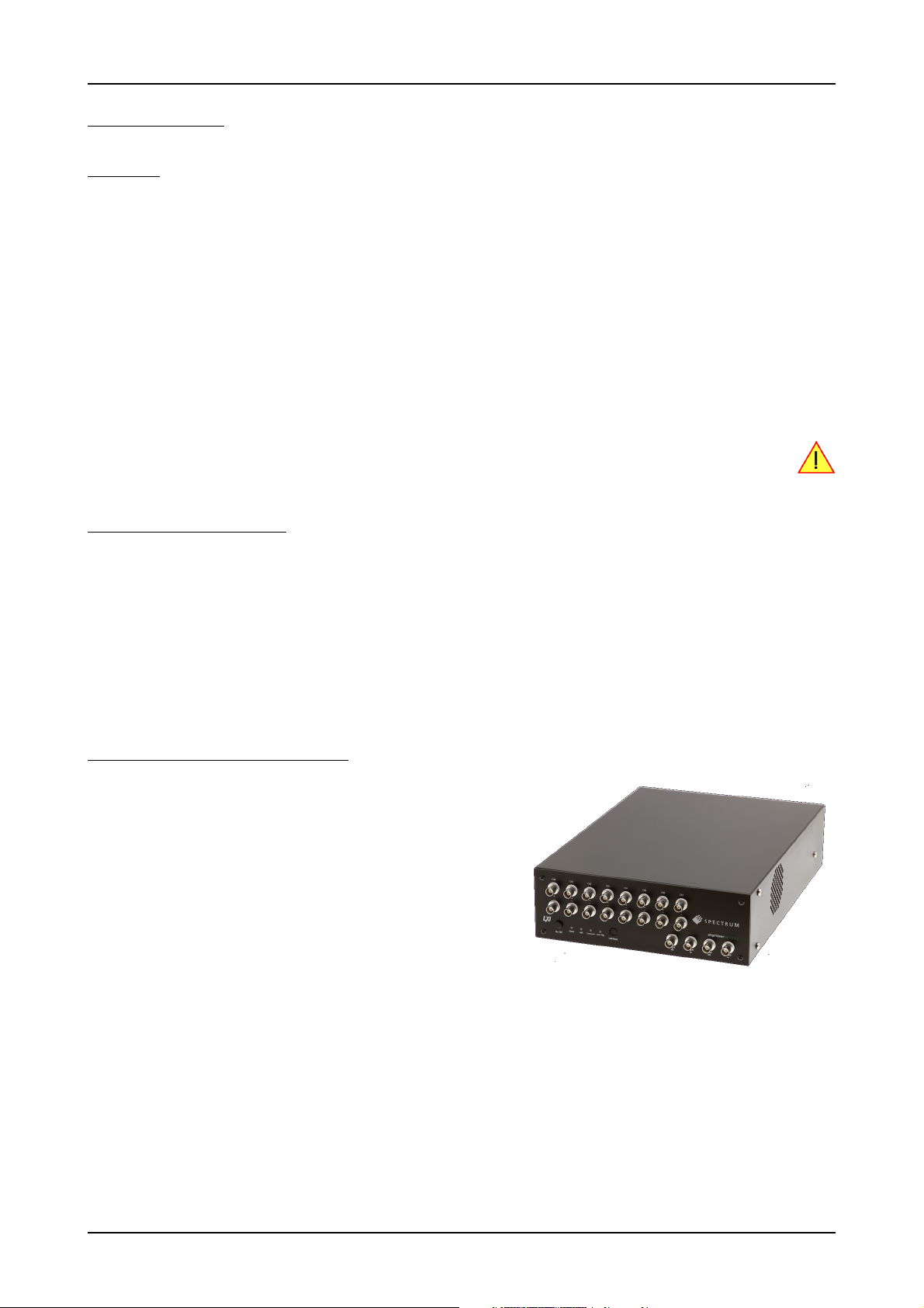
digitizerNETBOX Overview
The series of digitizerNETBOX products are remote powerful digitizer instruments with GBit Ethernet connection following the LXI Core 2011 standard. The
proven internal digitizer modules, a stable chassis, an embedded remote controller, sufficient air cooling and standard BNC connectors form an unique instrument that opens a lot of new application areas.
The digitizerNETBOX can be either directly connected to a PC or Laptop or it
can be connected to a company/institute LAN and can be accessed from any
PC within that LAN. Using the digitizerNETBOX offers the following benefits and
new possibilities compared to digitizer plug-in cards:
• Use a powerful digitizer without opening the PC and without mounting hardware inside the PC.
• Share the digitizer within a group of engineers that only need the instrument
from time to time.
• Place the digitizer directly near the signal sources and control it remotely from the desk.
• Use the instrument at different location without moving a complete system. One just needs the digitizerNETBOX, a few cables and a Laptop.
• Use the digitizer as s mobile data acquisition device with the DC power option (DN2.xxx only).
(c) Spectrum GmbH 9
Page 10

Internal Digitizer Modules Introduction
Internal Digitizer Modules
The digitizerNETBOX products internally consist of either digitizer modules that are accessed and programmed in a similiar way as the Spectrum digitizer cards themselves.
Accessing the digitizerNETBOX by software therefore is nearly identical to accessing the same plug-in cards.
Throughout the manual all programming and software usage will be described for the internal digitizer modules.
Differences between plain cards and digitizer modules inside the digitizerNETBOX
Feature Plain M2i-Express Card Installed inside digitizerNETBOX
Trigger Input B Only available as part of option BaseXIO Available as standard Available as standard
Timestamp
Reference Clock Input
Option BaseXIO Option can be ordered with purchase Not available Not available
Option Star-Hub Option can be ordered and allows to connect
Standard Memory 512 MSamples/256 MSamples per card
Maximum Memory 2 GSamples/1 GSamples per card
Feature Plain M4i-Express Card Installed inside digitizerNETBOX
Option Star-Hub Option can be ordered and allows to connect
Standard Memory 4 GSamples per card: M4i.22xx
Maximum Memory 4 GSamples per card: M4i.22xx
Feature Plain M2p-Express Card Installed inside digitizerNETBOX
Option Star-Hub Option can be ordered and allows to connect
Standard Memory 512 MSamples per card 512 MSamples per module 512 MSamples per module
Maximum Memory 512 MSamples per card 512 MSamples per module 512 MSamples per module
Only available as part of option BaseXIO Available as standard Available as standard
5 or 16 cards
(for 8bit / 16bit samples)
(for 8bit / 16bit samples)
8 cards
2 GSamples per card: M4i.44xx
2 GSamples per card: M4i.44xx
either 6 or 16 cards
DN2.20x, DN2.46x, DN2.47x,
DN2.48x, DN2.49x
Option installed internally in all digitizerNETBOXes
with two internal modules
1 GSamples/512 MSamples per module
(for 8bit / 16bit samples)
2 GSamples/1 GSamples per module
(for 8bit / 16bit samples)
DN2.22x and DN2.44x
Option installed internally in all digitizerNETBOXes
with two internal modules
4 GSamples per module in DN2.22x
2 GSamples per module in DN2.44x
4 GSamples per module in DN2.22x
2 GSamples per module in DN2.44x
DN2.59x
Option installed internally in all models
with two internal modules
Installed inside digitizerNETBOX
DN6.20x, DN6.46x, DN6.49x
Option installed internally in all models
1 GSamples/512 MSamples per module
(for 8bit / 16bit samples)
2 GSamples/1 GSamples per module
(for 8bit / 16bit samples)
Installed inside digitizerNETBOX
DN6.22x and DN6.44x
Option installed internally in all models
4 GSamples per module in DN6.22x
2 GSamples per module in DN6.44x
4 GSamples per module in DN6.22x
2 GSamples per module in DN6.44x
Installed inside digitizerNETBOX
DN6.59x
Option installed internally in all models
10 digitizerNETBOX DN2.44x Manual / DN6.44x Manual
Page 11

Introduction Internal Digitizer Modules
Overview of digitizer modules inside the DN2-44x and DN6-44x digitizerNETBOX
digitizerNETBOX
model
DN2
DN2.441-02 16 Bit 2 x SE 130 MS/s 1 module M4i.4410-x8 - INST0 2 GSamples no option
DN2.441-04 16 Bit 4 x SE 130 MS/s 1 module M4i.4411-x8 - INST0 2 GSamples no option
DN2.441-08 16 Bit 8 x SE 130 MS/s 2 modules M4i.4411-x8 yes INST1 2 GSamples no option
DN2.442-02 16 Bit 2 x SE 250 MS/s 1 module M4i.4420-x8 - INST0 2 GSamples no option
DN2.442-04 16 Bit 4 x SE 250 MS/s 1 module M4i.4421-x8 - INST0 2 GSamples no option
DN2.442-08 16 Bit 8 x SE 250 MS/s 2 modules M4i.4421-x8 yes INST1 2 GSamples no option
DN2.445-02 14 Bit 2 x SE 500 MS/s 1 module M4i.4450-x8 - INST0 2 GSamples no option
DN2.445-04 14 Bit 4 x SE 500 MS/s 1 module M4i.4451-x8 - INST0 2 GSamples no option
DN2.445-08 14 Bit 8 x SE 500 MS/s 2 modules M4i.4451-x8 yes INST1 2 GSamples no option
DN2.447-02 16 Bit 2 x SE 180 MS/s 1 module M4i.4470-x8 - INST0 2 GSamples no option
DN2.447-04 16 Bit 4 x SE 180 MS/s 1 module M4i.4471-x8 - INST0 2 GSamples no option
DN2.447-08 16 Bit 8 x SE 180 MS/s 2 modules M4i.4471-x8 yes INST1 2 GSamples no option
DN2.448-02 14 Bit 2 x SE 400 MS/s 1 module M4i.4480-x8 - INST0 2 GSamples no option
DN2.448-04 14 Bit 4 x SE 400 MS/s 1 module M4i.4481-x8 - INST0 2 GSamples no option
DN2.448-08 14 Bit 8 x SE 400 MS/s 2 modules M4i.4481-x8 yes INST1 2 GSamples no option
DN6
DN6.441-12 16 Bit 12 x SE 130 MS/s 3 modules M4i.4411-x8 yes INST0 2 GSamples no option
DN6.441-16 16 Bit 16 x SE 130 MS/s 4 modules M4i.4411-x8 yes INST0 2 GSamples no option
DN6.441-20 16 Bit 20 x SE 130 MS/s 5 modules M4i.4411-x8 yes INST1 2 GSamples no option
DN6.441-24 16 Bit 24 x SE 130 MS/s 6 modules M4i.4411-x8 yes INST2 2 GSamples no option
DN6.442-12 16 Bit 12 x SE 250 MS/s 3 modules M4i.4421-x8 yes INST0 2 GSamples no option
DN6.442-16 16 Bit 16 x SE 250 MS/s 4 modules M4i.4421-x8 yes INST0 2 GSamples no option
DN6.442-20 16 Bit 20 x SE 250 MS/s 5 modules M4i.4421-x8 yes INST1 2 GSamples no option
DN6.442-24 16 Bit 24 x SE 250 MS/s 6 modules M4i.4421-x8 yes INST2 2 GSamples no option
DN6.445-12 14 Bit 12 x SE 500 MS/s 3 modules M4i.4451-x8 yes INST0 2 GSamples no option
DN6.445-16 14 Bit 16 x SE 500 MS/s 4 modules M4i.4451-x8 yes INST0 2 GSamples no option
DN6.445-20 14 Bit 20 x SE 500 MS/s 5 modules M4i.4451-x8 yes INST1 2 GSamples no option
DN6.445-24 14 Bit 24 x SE 500 MS/s 6 modules M4i.4451-x8 yes INST2 2 GSamples no option
DN6.447-12 16 Bit 12 x SE 180 MS/s 3 modules M4i.4471-x8 yes INST0 2 GSamples no option
DN6.447-16 16 Bit 16 x SE 180 MS/s 4 modules M4i.4471-x8 yes INST0 2 GSamples no option
DN6.447-20 16 Bit 20 x SE 180 MS/s 5 modules M4i.4471-x8 yes INST1 2 GSamples no option
DN6.447-24 16 Bit 24 x SE 180 MS/s 6 modules M4i.4471-x8 yes INST2 2 GSamples no option
DN6.44812 14 Bit 12 x SE 400 MS/s 3 modules M4i.4481-x8 yes INST0 2 GSamples no option
DN6.448-16 14 Bit 16 x SE 400 MS/s 4 modules M4i.4481-x8 yes INST0 2 GSamples no option
DN6.448-20 14 Bit 20 x SE 400 MS/s 5 modules M4i.4481-x8 yes INST1 2 GSamples no option
DN6.448-24 14 Bit 24 x SE 400 MS/s 6 modules M4i.4481-x8 yes INST2 2 GSamples no option
Resolution Single-Ended
Differential
Max Speed Number of
Modules
Digitizer
Module Type
Internal
Star-Hub
Aux signals
on Module
Memory per
module
Max memory
per module
As an example: a DN2.441-08would be recognized and programmed inside the software as 2 cards of M4i.4411-x8 and 1 Star-Hub.
The auxilary signals (such as clock, trigger, etc.) are connected to one card only, which is the one carrying the Internal Star-Hub. That device
must be addressed for any external clock, trigger, etc. related setup.
(c) Spectrum GmbH 11
Page 12
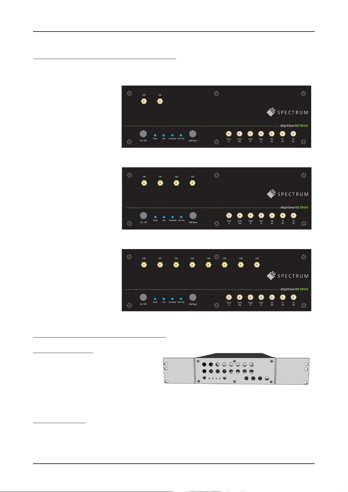
Different models of the DN2.44x series Introduction
Different models of the DN2.44x series
The following overview shows the different available models of the DN2.44x series. They differ in the number of internally mounted digitizer
modules and the number of available channels.
• DN2.441-02
• DN2.442-02
• DN2.445-02
• DN2.447-02
• DN2.448-02
• DN2.441-04
• DN2.442-04
• DN2.445-04
• DN2.447-04
• DN2.448-04
• DN2.441-08
• DN2.442-08
• DN2.445-08
• DN2.447-08
• DN2.448-08
Additional options for DN2 products
19“ Rack Mount Kit
The rack mount kit allows to mount the
digitizerNETBOX/generatorNETBOX into a standard 19“
rack. The digitizerNETBOX/generatorNETBOX DN2 recquires two height units of the 19“ rack.
Multiple digitizerNETBOX/generatorNETBOX products can
be mounted one on top of the other.
It is not possible to mount two digitizerNETBOX/generatorNETBOX DN2 products side by side into one 19“ slot.
DC Power Supply
The DC power supply option is factory mounted and allows the connection of a DC source directly to the digitizerNETBOX/generatorNETBOX.
12 digitizerNETBOX DN2.44x Manual / DN6.44x Manual
Page 13
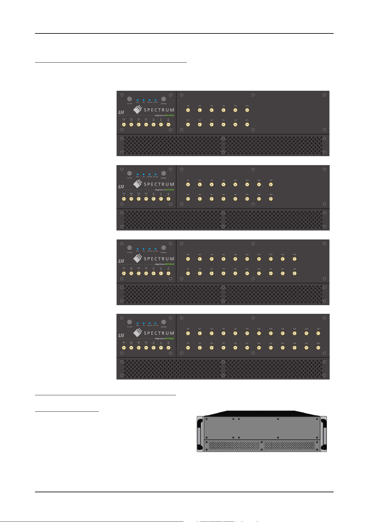
Introduction Different models of the DN6.44x series
Different models of the DN6.44x series
The following overview shows the different available models of the DN6.44x series. They differ in the number of internally mounted digitizer
modules and the number of available channels.
• DN6.441-12
• DN6.442-12
• DN6.445-12
• DN6.447-12
• DN6.448-12
• DN6.441-16
• DN6.442-16
• DN6.445-16
• DN6.447-16
• DN6.448-16
• DN6.441-20
• DN6.442-20
• DN6.445-20
• DN6.447-20
• DN6.448-20
• DN6.441-24
• DN6.442-24
• DN6.445-24
• DN6.447-24
• DN6.448-24
Additional options for DN6 products
19“ Rack Mount Kit
The rack mount kit allows to mount the
digitizerNETBOX/generatorNETBOX into a standard 19“ rack.
The device then recquires three height units of the 19“ rack.
Multiple digitizerNETBOX/generatorNETBOX products can be mounted one on top of the other.
(c) Spectrum GmbH 13
Page 14
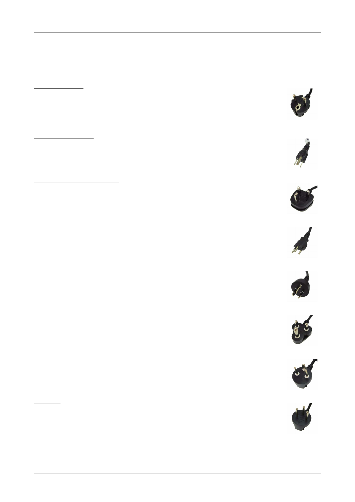
AC Cable Options Introduction
AC Cable Options
As a standard a Central European power cable Cab-Pwr-001 is included in the delivery. Other power cables can be ordered separately to
connect your products with your local power connection system. The following power cable options are available:
001: Central Europe
The standard cable for central Europe is already included in all deliveries of system and box products like digitizerNETBOX. The power cable is suitable for Continental Europe, Central African Republic, United Arab Republic.
Cab-Pwr-001: 180 cm cable to CEE 7/VII
002: US, Japan, Taiwan
The power cable is suitable for US, Canada, Japan, Taiwan, Brazil, Mexico, Philippines, Colombia, Saudi Arabia
Cab-Pwr-002: 180 cm cable for NEMA5-15P
003: United Kingdom, Hong Kong
The power cable is suitable for United Kingdom, Hong Kong, Cyprus, Nigeria, Singapore, Zimbabwe.
Cab-Pwr-003: 180 cm cable to BS 1363A
004: Switzerland
The power cable is suitable for Switzerland.
Cab-Pwr-004: 180 cm cable for SEV type 12
005: Australia, China
The power cable is suitable for Australia, New Zealand, Mainland China, Argentina
Cab-Pwr-005: 180 cm cable for AS 3112
006: India, South Africa
The power cable is suitable for India and South Africa
Cab-Pwr-006: 180 cm cable for IEC 83-B1
007: Denmark
The power cable is suitable for Denmark
Cab-Pwr-007: 180 cm cable for SR 107-2-D
008: Israel
The power cable is suitable for Israel
Cab-Pwr-008: 180 cm cable for SI 32
14 digitizerNETBOX DN2.44x Manual / DN6.44x Manual
Page 15
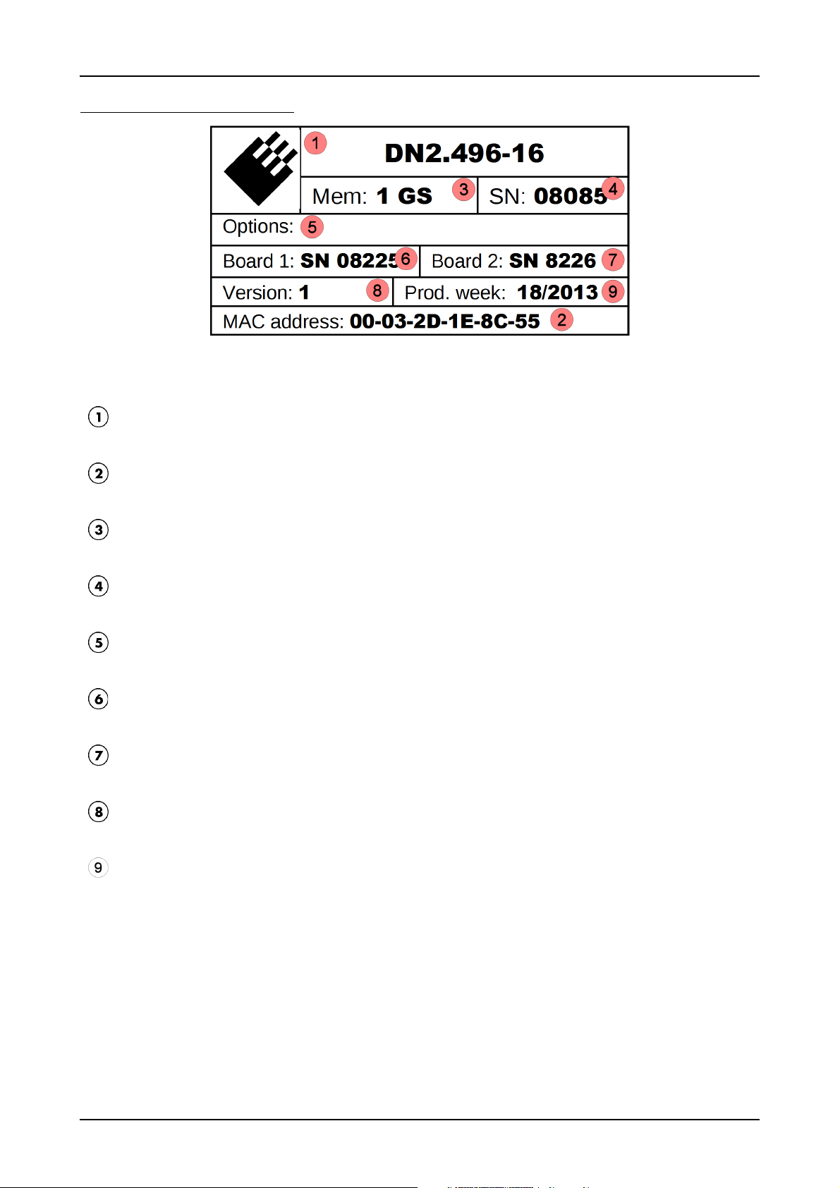
Introduction The Spectrum type plate
The Spectrum type plate
The Spectrum type plate, which consists of the following components, can be found on the back of all netbox products. Please check whether
the printed information is the same as the information on your delivery note. All this information can also be read out by software:
The digitizerNETBOX/generatorNETBOX type, consisting of the abbrevaition for the digitizerNETBOX/generatorNETBOX chassis
type (DN2 in this example), the model type (496) and the number of channels (16)
The MAC address of the device. The MAX address is fixed and cannot be changed by the user. To check the MAC address by
software one can use the integrated web pages of the digitizerNETBOX/generatorNETBOX.
The installed complete data acquisition memory of the digitizerNETBOX/generatorNETBOX. As in our example there are two internal digitizer modules installed the memory is shared between them. Each digitizer module has 512 MSamples.
The serial number of the digitizerNETBOX/generatorNETBOX itself. This is the serial number also found on the delivery note.
Installed options of the digitizerNETBOX/generatorNETBOX.
The serial number of the first internal digitizer module.
The serial number of the second internal digitizer module.
The hardware version of the digitizerNETBOX/generatorNETBOX. The hardware and firmware versions of the installed
digitizer/generator modules are found using the Spectrum Control Center.
The date of production of the digitizerNETBOX/generatorNETBOX consisting of the calendar week and the year.
Please always supply us with the above information, especially the serial number in case of support request. That
allows us to answer your questions as soon as possible. Thank you.
(c) Spectrum GmbH 15
Page 16
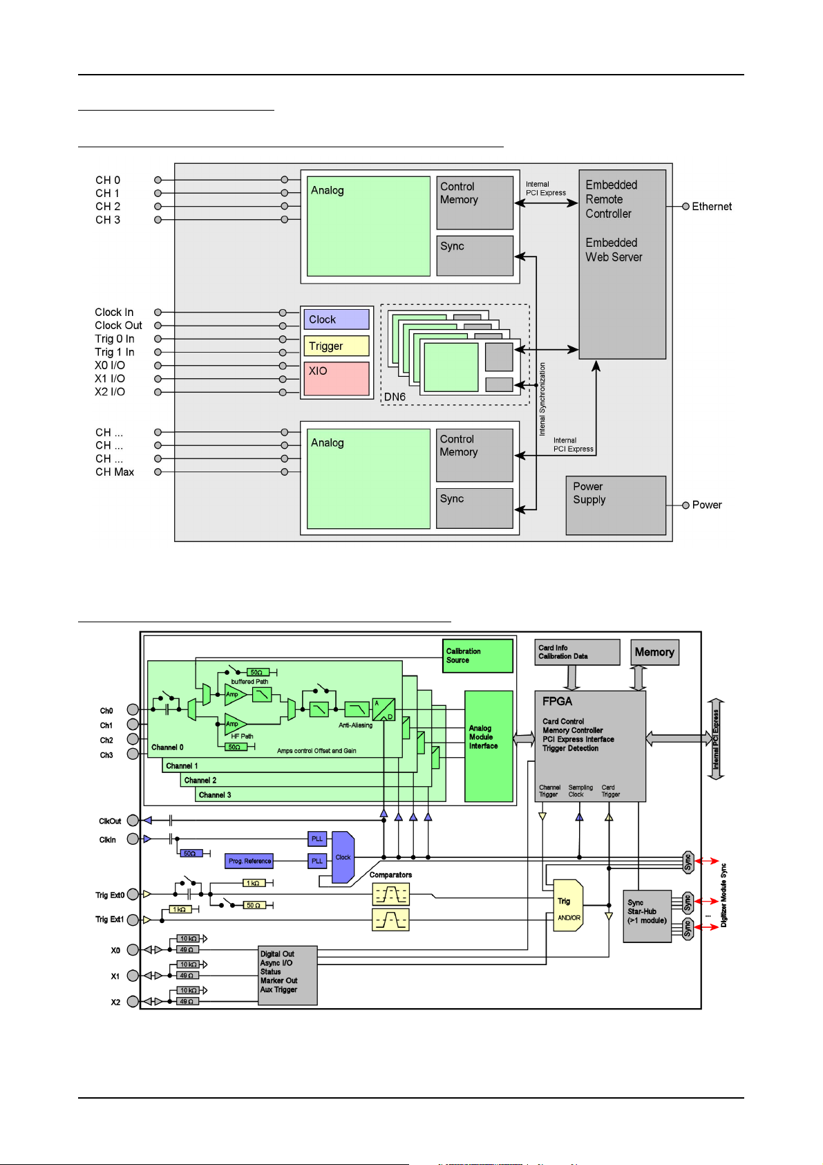
Hardware information Introduction
Hardware information
Block diagram of digitizerNETBOX DN2.44x and DN6.44x:
• The number of maximum channels and internal digitizer modules and existance of a synchronization Star-Hub is model dependent.
• The internal module to which the auxilary I/O lines are connected is model dependent. Consult „Internal Digitizer modules“ chapter.
Block diagram of a single internal digitizer module:
16 digitizerNETBOX DN2.44x Manual / DN6.44x Manual
Page 17

Introduction Hardware information
DN2 / DN6 Technical Data
Analog Inputs
Resolution 130 MS/s up to 250 MS/s
400 MS/s and 500 MS/s
Input Type Single-ended
ADC Differential non linearity (DNL) ADC only ±0.5 LSB (14 Bit ADC), ±0.4 LSB (16 Bit ADC)
ADC Integral non linearity (INL) ADC only ±2.5 LSB (14 Bit ADC), ±10.0 LSB (16 Bit ADC)
ADC Word Error Rate (WER) max. sampling rate
Channel selection software programmable 1, 2, or 4 (maximum is model dependent)
Bandwidth filter activate by software 20 MHz bandwidth with 3rd order Butterworth filtering
16 bit (441, 442, 447)
14 bit (445, 448)
-12
10
Input Path Types software programmable
Analog Input impedance software programmable
50 Ω (HF) Path
50 Ω 1 MΩ || 25 pF or 50 Ω
Buffered (high impedance) Path
Input Ranges software programmable ±500 mV, ±1 V, ±2.5 V, ±5 V ±200 mV, ±500 mV, ±1 V, ±2 V, ±5 V, ±10 V
Programmable Input Offset Frontend HW-Version < V9 not available not available
Programmable Input Offset Frontend HW-Version >= V9 –100%..0% on all ranges –100%..0% on all ranges except ±1 V and ±10 V
Input Coupling software programmable AC/DC AC/DC
Offset error (full speed) after warm-up and calibration < 0.1% of range < 0.1% of range
Gain error (full speed) after warm-up and calibration < 1.0% of reading < 1.0% of reading
Over voltage protection range ≤ ±1V 2 Vrms
Over voltage protection range ≥ ±2V 6 Vrms
±5 V (1 M
±30 V (1 M
Ω), 5 Vrms (50 Ω)
Ω), 5 Vrms (50 Ω)
Max DC voltage if AC coupling active ±30 V ±30 V
Relative input stage delay Bandwidth filter disabled: 0 ns
Bandwidth filter enabled: 14.7 ns
Bandwidth filter disabled: 3.8 ns
Bandwidth filter enabled: 18.5 ns
Crosstalk 1 MHz sine signal range ±1V ≤96 dB ≤93 dB
Crosstalk 20 MHz sine signal range ±1V ≤82 dB ≤82 dB
Crosstalk 1 MHz sine signal range ±5V ≤97 dB ≤85 dB
Crosstalk 20 MHz sine signal range ±5V ≤82 dB ≤82 dB
M4i.441x
M4x.441x
DN2.441-xx
DN6.441-xx
M4i.442x
M4x.442x
DN2.442-xx
DN6.442-xx
M4i.445x
M4x.445x
DN2.445-xx
DN6.445-xx
M4i.447x
M4x.447x
DN2.447-xx
DN6.447-xx
M4i.448x
M4x.448x
DN2.448-xx
DN6.448-xx
lower bandwidth limit (DC coupling) 0 Hz 0 Hz 0 Hz 0 Hz 0 Hz
lower bandwidth limit (AC coupled, 50 Ω)
lower bandwidth limit (AC coupled, 1 MΩ)
-3 dB bandwidth (HF path, AC coupled, 50 Ω)
Flatness within ±0.5 dB (HF path, AC coupled, 50 Ω)
-3 dB bandwidth (Buffered path, DC coupled, 1 MΩ)
< 30 kHz < 30 kHz < 30 kHz < 30 kHz < 30 kHz
< 2 Hz < 2 Hz < 2 Hz < 2 Hz < 2 Hz
65 MHz 125 MHz 250 MHz 125 MHz 250 MHz
40 MHz 80 MHz 160 MHz 80 MHz 160 MHz
50 MHz 85 MHz 85 MHz (V1.1)
125 MHz (V1.2)
85 MHz 125 MHz (V1.2)
-3 dB bandwidth (bandwidth filter enabled) 20 MHz 20 MHz 20 MHz 20 MHz 20 MHz
Trigger
Available trigger modes software programmable Channel Trigger, External, Software, Window, Re-Arm, Or/And, Delay, PXI (M4x only)
Channel trigger level resolution software programmable 14 bit
Trigger engines 1 engine per channel with two individual levels, 2 external triggers
Trigger edge software programmable Rising edge, falling edge or both edges
Trigger delay software programmable 0 to (8GSamples - 16) = 8589934576 Samples in steps of 16 samples
Multi, Gate, ABA: re-arming time 40 samples (+ programmed pretrigger)
Pretrigger at Multi, ABA, Gate, FIFO, Boxcar software programmable 16 up to [8192 Samples in steps of 16)
Posttrigger software programmable 16 up to 8G samples in steps of 16 (defining pretrigger in standard scope mode)
Memory depth software programmable 32 up to [installed memory / number of active channels] samples in steps of 16
Multiple Recording/ABA segment size, Boxcar software programmable 32 up to [installed memory / 2 / active channels] samples in steps of 16
Trigger accuracy (all sources) 1 sample
Boxcar (high-resolution) average factor software programmable 2, 4, 8, 16, 32, 64, 128 or 256
Timestamp modes software programmable Standard, Startreset, external reference clock on X0 (e.g. PPS from GPS, IRIG-B)
Data format Std., Startreset: 64 bit counter, increments with sample clock (reset manually or on start)
RefClock: 24 bit upper counter (increment with RefClock)
40 bit lower counter (increments with sample clock, reset with RefClock)
Extra data software programmable none, acquisition of X0/X1/X2 inputs at trigger time, trigger source (for OR trigger)
Size per stamp 128 bit = 16 bytes
External trigger Ext0 Ext1
External trigger impedance software programmable
50 Ω /1 kΩ 1 kΩ
External trigger coupling software programmable AC or DC fixed DC
External trigger type Window comparator Single level comparator
External input level
External trigger sensitivity
(minimum required signal swing)
±10 V (1 kΩ), ±2.5 V (50 Ω),
2.5% of full scale range 2.5% of full scale range = 0.5 V
±10 V
External trigger level software programmable ±10 V in steps of 1 mV ±10 V in steps of 1 mV
External trigger maximum voltage ±30V ±30 V
External trigger bandwidth DC
50 Ω
1 kΩ
DC to 200 MHz
DC to 150 MHz
n.a.
DC to 200 MHz
(c) Spectrum GmbH 17
Page 18
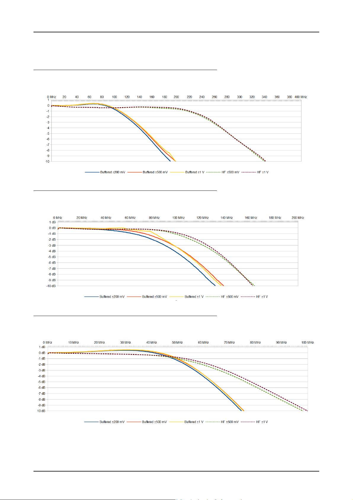
Hardware information Introduction
Trigger edge software programmable Rising edge, falling edge or both edges
External trigger bandwidth AC
Minimum external trigger pulse width ≥ 2 samples ≥ 2 samples
50 Ω
20 kHz to 200 MHz n.a.
Frequency Response M4i.445x, M4x.445x, DN2.445-xx and DN6.445-xx
Sampling Rate 500 MS/s
HF Path 50
Buffered Path 1 M
Ω, AC coupling, no filter
Ω, AC Coupling, no filter
Frequency Response M4i.442x, M4x.442x, DN2.442-xx and DN6.442-xx
Sampling Rate 250 MS/s
HF Path 50
Buffered Path 1 M
Ω, AC coupling, no filter
Ω, AC Coupling, no filter
Frequency Response M4i.441x, M4x.441x, DN2.441-xx and DN6.441-xx
Sampling Rate 130 MS/s
HF Path 50
Buffered Path 1 M
18 digitizerNETBOX DN2.44x Manual / DN6.44x Manual
Ω, AC coupling, no filter
Ω, AC Coupling, no filter
Page 19

Introduction Hardware information
Clock
Clock Modes software programmable internal PLL, external reference clock, Star-Hub sync (M4i only), PXI Reference Clock (M4x only)
Internal clock accuracy ≤ ±20 ppm
Internal clock setup granularity standard clock mode divider: maximum sampling rate divided by:
Internal clock setup granularity special clock mode only 1 Hz (reduced gain accuracy when using special clock mode), not available when synchroniz-
Clock setup range gaps special clock mode only unsetable clock speeds: 17.5 MHz to 17.9 MHz, 35.1 MHz to 35.8 MHz, 70 MHz to 72 MHz,
External reference clock range software programmable ≥ 10 MHz and ≤ 1 GHz
External reference clock input impedance
External reference clock input coupling AC coupling
External reference clock input edge Rising edge
External reference clock input type Single-ended, sine wave or square wave
External reference clock input swing 0.3 V peak-peak up to 3.0 V peak-peak
External reference clock input max DC voltage ±30 V (with max 3.0 V difference between low and high level)
External reference clock input duty cycle requirement 45% to 55%
Internal ADC clock output type Single-ended, 3.3V LVPECL
Internal ADC clock output frequency standard clock mode Fixed to maximum sampling rate (500 MS/s, 250 MS/s or 130 MS/s depending on type)
Internal ADC clock output frequency special clock mode 445x models (500 MS/s): ADC clock in the range between 80 MS/s and 500 MS/s
Star-Hub synchronization clock modes software selectable Internal clock (standard clock mode only, special clock mode not allowed), External reference
ABA mode clock divider for slow clock software programmable 16 up to (128k - 16) in steps of 16
Channel to channel skew on one card < 60 ps (typical)
Skew between star-hub synchronized cards < 130 ps (typical, preliminary)
1, 2, 4, 8, 16, ... up to 131072 (full gain accuracy)
ing multiple cards
140 MHz to 144 MHz, 281 MHz to 287 MHz
50 Ω fixed
448x models (400 MS/s): ADC clock in the range between 80 MS/s and 400 MS/s
442x models (250 MS/s): ADC clock in the range between 40 MS/s and 250 MS/s
447x models (180 MS/s): ADC clock in the range between 40 MS/s and 180 MS/s
441x models (130 MS/s): ADC clock in the range between 40 MS/s and 130 MS/s
clock
M4i.441x
M4x.441x
DN2.441-xx
DN6.441-xx
M4i.442x
M4x.442x
DN2.442-xx
DN6.442-xx
M4i.445x
M4x.445x
DN2.445-xx
DN6.445-xx
M4i.447x
M4x.447x
DN2.447-xx
DN6.447-xx
M4i.448x
M4x.448x
DN2.448-xx
DN6.448-xx
ADC Resolution 16 bit 16 bit 14 bit 16 bit 14 bit
max sampling clock 130 MS/s 250 MS/s 500 MS/s 180 MS/s 400 MS/s
min sampling clock (standard clock mode) 3.814 kS/s 3.814 kS/s 3.814 kS/s 3.814 kS/s 3.814 kS/s
min sampling clock (special clock mode) 0.610 kS/s 0.610 kS/s 0.610 kS/s 0.610 kS/s 0.610 kS/s
Block Average Signal Processing Option M4i.44xx/M4x.44xx/DN2.44x/DN6.44x Series
Minimum Waveform Length 32 samples 32 samples
Minimum Waveform Stepsize 16 samples 16 samples
Maximum Waveform Length 1 channel active 128 kSamples 32 kSamples
Maximum Waveform Length 2 channels active 64 kSamples 16 kSamples
Maximum Waveform Length 4 or more channels active 32 kSamples 8 kSamples
Minimum Number of Averages 2 2
Maximum Number of Averages 65536 (64k) 65536 (64k)
Data Output Format fixed 32 bit signed integer 32 bit signed integer
Re-Arming Time between waveforms 40 samples (+ programmed pretrigger) 40 samples (+ programmed pretrigger)
Re-Arming Time between end of average to start of
next average
Firmware ≥ V1.14 (August 2015) Firmware < V1.14
Depending on programmed segment
length, max 100 µs
40 samples (+ programmed pretrigger)
Block Statistics Signal Processing Option M4i.44xx/M4x.44xx/DN2.44x/DN6.44x Series
Minimum Waveform Length 32 samples
Minimum Waveform Stepsize 16 samples
Maximum Waveform Length Standard Acquisition 2 GSamples / channels
Maximum Waveform Length FIFO Acquisition 2 GSamples
Data Output Format fixed 32 bytes statistics summary
Statistics Information Set per Waveform Average, Minimum, Maximum, Position Minimum, Position Maximum, Trigger Timestamp
Re-Arming Time between Segments 40 samples (+ programmed pretrigger)
(c) Spectrum GmbH 19
Page 20

Hardware information Introduction
Multi Purpose I/O lines (front-plate)
Number of multi purpose lines three, named X0, X1, X2
Input: available signal types software programmable Asynchronous Digital-In, Synchronous Digital-In, Timestamp Reference Clock
Input: impedance
10 kΩ to 3.3 V
Input: maximum voltage level -0.5 V to +4.0 V
Input: signal levels 3.3 V LVTTL
Input: bandwith 125 MHz
Output: available signal types software programmable Asynchronous Digital-Out, Trigger Output, Run, Arm, PLL Refclock, System Clock
Output: impedance
50 Ω
Output: signal levels 3.3 V LVTTL
Output: type 3.3V LVTTL, TTL compatible for high impedance loads
Output: drive strength
Capable of driving 50 Ω loads, maximum drive strength ±48 mA
Output: update rate 14bit, 16 bit ADC resolution sampling clock
Output: update rate 8 bit ADC resolution Current sampling clock < 1.25 GS/s : sampling clock
Current sampling clock > 1.25 GS/s and < 2.50 GS/s : ½ sampling clock
Current sampling clock > 2.50 GS/s and < 5.00 GS/s : ¼ sampling clock
Connectors
Analog Channels SMA male (one for each single-ended input) Cable-Type: Cab-3fa-xx-xx
Clock Input SMA male Cable-Type: Cab-3fa-xx-xx
Clock Output SMA male Cable-Type: Cab-3fa-xx-xx
Trg0 Input SMA male Cable-Type: Cab-3fa-xx-xx
Trg1 Input SMA male Cable-Type: Cab-3fa-xx-xx
X0/Trigger Output/Timestamp Reference Clock programmable direction SMA male Cable-Type: Cab-3fa-xx-xx
X1 programmable direction SMA male Cable-Type: Cab-3fa-xx-xx
X2 programmable direction SMA male Cable-Type: Cab-3fa-xx-xx
Option digitizerNETBOX/generatorNETBOX embedded server (DN2.xxx-Emb, DN6.xxx-Emb)
CPU Intel Quad Core 2 GHz
System memory 4 GByte RAM
System data storage Internal 128 GByte SSD
Development access Remote Linux command shell (ssh), no graphical interface (GUI) available
Accessible Hardware Full access to Spectrum instruments, LAN, front panel LEDs, RAM, SSD
Integrated operating system OpenSuse 12.2 with kernel 3.4.6.
Ethernet specific details
LAN Connection Standard RJ45 or Ethernet Buccaneer(R) for screw connection
LAN Speed Auto Sensing: GBit Ethernet, 100BASE-T, 10BASE-T
Sustained Streaming speed DN2.20, DN2.46, DN2.47, DN2.49, DN2.60 up to 70 MByte/s
DN6.46, DN6.49
DN2.59, DN2.22, DN2.44, DN2.66 up to 100 MByte/s
DN6.59, DN6.22, DN6.44, DN6.66
Used LAN Ports Webserver: 80
VISA Discovery Protocol: 111, 9757
Spectrum Remote Server: 1026, 5025
mDNS Daemon: 5353
UPNP Daemon: 1900
Power connection details
Mains AC power supply Input voltage: 100 to 240 VAC, 50 to 60 Hz
AC power supply connector IEC 60320-1-C14 (PC standard coupler)
Power supply cord power cord included for Schuko contact (CEE 7/7)
Certification, Compliance, Warranty
EMC Immunity Compliant with CE Mark
EMC Emission Compliant with CE Mark
Product warranty 5 years starting with the day of delivery
Software and firmware updates Life-time, free of charge
20 digitizerNETBOX DN2.44x Manual / DN6.44x Manual
Page 21
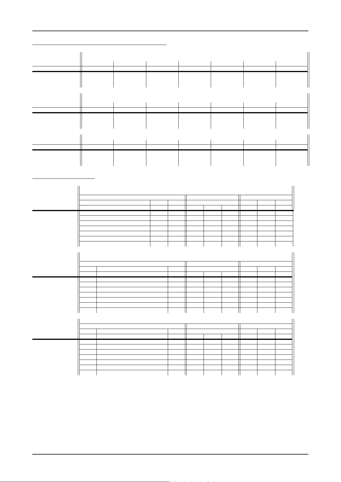
Introduction Hardware information
RMS Noise Level (Zero Noise), typical figures
M4i.445x, M4x.445x, DN2.445-xx and DN6.445-xx, 14 Bit 500 MS/s
Input Range ±200 mV ±500 mV ±1 ±2 V ±2.5 V ±5 V ±10 V
Voltage resolution
24.4 µV61.0 µV 122.1 µV 244.1 µV305.2 µV610.4 µV 1.22 mV
HF path, DC, fixed 50 Ω
Buffered path, full bandwidth
Buffered path, BW limit active
<3.8 LSB <93 µV <2.7 LSB <165 µV <2.1 LSB <256 µV <3.8 LSB <928 µV <2.7 LSB <1.65 mV <2.0 LSB <2.44 mV
<2.2 LSB <54 µV <2.0 LSB <122 µV <2.0 LSB <244 µV <3.2 LSB <781 µV <2.3 LSB <1.40 mV <2.0 LSB <2.44 mV
Input Range ±200 mV ±500 mV ±1 ±2 V ±2.5 V ±5 V ±10 V
Voltage resolution
6.1 µV15.3 µV 30.5 µV 61.0 µV 76.3 µV152.6 µV305.2 µV
HF path, DC, fixed 50 Ω
Buffered path, full bandwidth
Buffered path, BW limit active
<11 LSB <67 µV <7.8 LSB <119 µV <7.1 LSB <217 µV <12 LSB <732 µV <8.1 LSB <1.24 mV <7.1 LSB <2.17 mV
<7.9 LSB <48 µV <7.0 LSB <107 µV <6.9 LSB <211 µV <9.8 LSB <598 µV <7.2 LSB <1.10 mV <7.1 LSB <2.17 mV
M4i.448x, M4x.448x, DN2.448-xxx and DN6.448-xx, 14 Bit 400 MS/s
<1.9 LSB <116 µV <1.9 LSB <232 µV <1.9 LSB <5 80 µV <1.9 LSB <1.16 mV
M4i.442x, M4x.442x, DN2.442-xx and DN6.442-xx, 16 Bit 250 MS/s
M4i.447x, M4x.447x, DN2.447-xx and DN6.447-xx, 16 Bit 180 MS/s
<6.9 LSB <53 µV <6.9 LSB <211 µV <6.9 LSB <526 µV <6.9 LSB <1.05 mV
Input Range ±200 mV ±500 mV ±1 ±2 V ±2.5 V ±5 V ±10 V
M4i.441x, M4x.441x, DN2.441-xx and DN6.441-xx, 16 Bit 130 MS/s
Voltage resolution (1)
HF path, DC, fixed 50 Ω
Buffered path, full bandwidth
Buffered path, BW limit active
6.1 µV15.3 µV 30.5 µV 61.0 µV 76.3 µV152.6 µV305.2 µV
<5.9 LSB <90 µV <5.9 LSB <180 µV <5.9 LSB <450 µV <5.9 LSB <900 µV
<8.5 LSB <52 µV <6.5 LSB <99 µV <5.9 LSB <180 µV <11 LSB <671 µV <7.0 LSB <1.07 mV <6.1 LSB <1.86 mV
<7.0 LSB <43 µV <6.1 LSB <93 µV <5.9 LSB <180 µV <9.6 LSB <586 µV <6.7 LSB <1.02 mV <6.1 LSB <1.86 mV
Dynamic Parameters
M4i.445x, M4x.445x, DN2.445-xx and DN6.445-xx, 14 Bit 500 MS/s
Input Path HF path, AC coupled, fixed 50 Ohm Buffered path, BW limit Buffered path, full BW
Test signal frequency 10 MHz 40 MHz 70 MHz 10 MHz 10 MHz 40 MHz 70 MHz
Input Range ±500mV ±1V ±2.5V ±5V ±1V ±1V ±200mV ±500mV ±1V ±500mV ±500mV ±500mV
THD (typ) (dB
SNR (typ) (dB)
SFDR (typ), excl. harm. (dB)
SFDR (typ), incl. harm. (dB)
SINAD/THD+N (typ) (dB)
ENOB based on SINAD (bit)
ENOB based on SNR (bit)
<-75.9 dB <-75.8 dB <-75.2 dB <-7 4.8 dB <-72.5 dB <-67.4 dB <- 71.4 dB <-72.1 dB <-68.6 dB <- 65.0 dB <-58.6 dB <-54.4 dB
>67.8 dB >67.9 dB >68.0 dB >68.0 dB >69.5 dB >67.5 dB >67.5 dB >68.0 dB >68.1 dB >67.3 dB >65.8 dB >65.6 dB
>88.1 dB >88.6 dB >85.2 dB >85.3 dB >88.0 dB >87.8 dB >87.3 dB >88.4 dB >87.5 dB >89.0 dB >88.9 dB >88.8 dB
>80.1 dB >80.0 dB >77.4 dB >77.3 dB >74.0 dB >69.9 dB >78.1 dB >73.5 dB >69.8 dB >67.5 dB >60.8 dB >56.0 dB
>67.2 dB >67.2 dB >67.2 dB >67.2 dB >67.7 dB >64.4 dB >66.5 dB >66.6 dB >65.3 dB >63.9 dB >57.9 dB >54.0 dB
>10.9 bit >10.9 bit >10.9 bit >10.9 bit >10.9 bit >10.4 bit >10.7 bit >10.8 bit >10.6 bit >10.3 bit >9.3 bit >8.7 bit
>11.0 bit >11.0 bit >11.0 bit >11.0 bit >11.0 bit >10.9 bit >10.9 bit >11.0 bit >11.0 bit >10.9 bit >10.6 bit >10.6 bit
Input Path HF path, AC coupled, fixed 50 Ohm Buffered path, BW limit Buffered path, full BW
Test signal frequency 1 MHz 10 MHz 40 MHz 10 MHz 1 MHz 10 MHz 40 MHz
Input Range ±1V ±500mV ±1V ±2.5V ±5V ±1V ±200mV ±500mV ±1V ±500mV ±500mV ±500mV
THD (typ) (dB
SNR (typ) (dB)
SFDR (typ), excl. harm. (dB)
SFDR (typ), incl. harm. (dB)
SINAD/THD+N (typ) (dB)
ENOB based on SINAD (bit)
ENOB based on SNR (bit)
<-73.1 dB <-74.0 dB <-74.1 dB <-7 4.1 dB <-74.1 dB <-62.9 dB <- 73.2 dB <-71.5 dB <-69.0 dB <-72.2 dB <-67.5 dB <49.8 dB
>71.9 dB >71.5 dB >71.5 dB >71.6 dB >71.6 dB >71.8 dB >69.8 dB >71.0 dB >71.2 dB >71.7 dB >71.0 dB >69.0 dB
>92.1 dB >90.4 dB >90.8 dB >90.1 dB >89.7 dB >90.2 dB >92.1 dB >92.0 dB >92.1 dB >90.0 dB >91.4 dB >92.5 dB
>74.4 dB >75.4 dB >75.5 dB >75.5 dB >75.5 dB >64.5 dB >75.0 dB >73.1 dB >69.8 dB >74.7 dB >67.8 dB >50.0 dB
>69.8 dB >69.6 dB >69.6 dB >69.6 dB >69.6 dB >62.2 dB >68.5 dB >68.2 dB >67.0 dB >68.8 dB >66.4 dB >48.9 dB
>11.3 bit >11.2 bit >11.2 bit >11.3 bit >11.3 bit >10.0 bit >11.1 bit >11.0 bit >10.8 bit >11.1 dB >10.7 bit >7.8 bit
>11.7 bit >11.6 bit >11.6 bit >11.6 bit >11.6 bit >11.6 dB >11.3 bit >11.5 bit >11.5 bit >11.6 dB >11.5 bit >11.2 bit
M4i.448x, M4x.448x, DN2.448-xxx and DN6.448-xx, 14 Bit 400 MS/s
M4i.442x, M4x.442x, DN2.442-xx and DN6.442-xx, 16 Bit 250 MS/s
M4i.447x, M4x.447x, DN2.447-xx and DN6.447-xx, 16 Bit 180 MS/s
Input Path HF path, AC coupled, fixed 50 Ohm Buffered path, BW limit Buffered path, full BW
M4i.441x, M4x.441x, DN2.441-xx and DN6.441-xx, 16 Bit 130 MS/s
Test signal frequency 1 MHz 10 MHz 10 MHz 1 MHz 10 MHz
Input Range ±1V ±500mV ±1V ±2.5V ±5V ±200mV ±500mV ±1V ±500mV ±500mV
THD (typ) (dB
SNR (typ) (dB)
SFDR (typ), excl. harm. (dB)
SFDR (typ), incl. harm. (dB)
SINAD/THD+N (typ) (dB)
ENOB based on SINAD (bit)
ENOB based on SNR (bit)
Dynamic parameters are measured at ±1 V input range (if no other range is stated) and 50Ω termination with the samplerate specified in the table. Measured parameters are averaged
20 times to get typical values. Test signal is a pure sine wave generated by a signal generator and a matching bandpass filter. Amplitude is >99% of FSR. SNR and RMS noise parameters
may differ depending on the quality of the used PC. SNR = Signal to Noise Ratio, THD = Total Harmonic Distortion, SFDR = Spurious Free Dynamic Range, SINAD = Signal Noise and Distortion, ENOB = Effective Number of Bits.
<-72.6 dB <-77.8 dB <-77.5 dB <-7 7.3 dB <-77.1 dB <-74.5 dB <-73.9 dB <-70.1 dB <-73.5 dB <73.4 dB
>72.2 dB >71.8 dB >71.9 dB >72.0 dB >72.0 dB >69.8 dB >71.2 dB >71.3 dB >71.1 dB >71.0 dB
>92.4 dB >97.0 dB >96.0 dB >95.2 dB >94.8 dB >89.0 dB >94.0 dB >94.5 dB >88.8 dB >93.5 dB
>73.7 dB >78.6 dB >78.2 dB >75.2 dB >75.1 dB >77.6 dB >77.8 dB >71.5 dB >74.7 dB >73.1 dB
>69.4 dB >70.8 dB >70.8 dB >70.9 dB >70.8 dB >69.0 dB >69.7 dB >68.2 dB >69.2 dB >69.2 dB
>11.2 bit >11.5 bit >11.5 bit >11.5 bit >11.5 bit >11.2 bit >11.3 bit >11.0 bit >11.2 bit >11.2 bit
>11.7 bit >11.6 bit >11.6 bit >11.6 bit >11.6 bit >11.3 bit >11.5 bit >11.5 bit >11.6 bit >11.6 bit
(c) Spectrum GmbH 21
Page 22
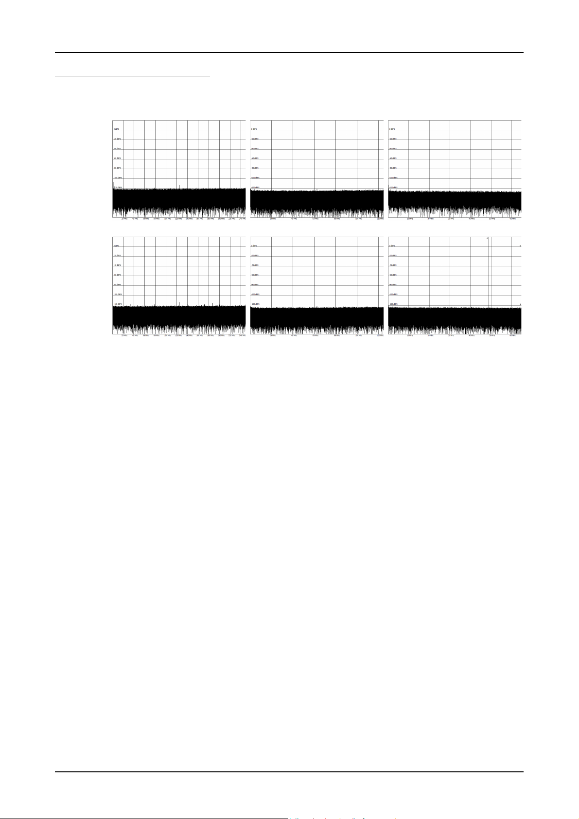
Hardware information Introduction
Noise Floor Plots (open inputs)
Buffered Path
1 MΩ, AC
±1 V range
HF Path
50 Ω, AC
±500 mV
M4i.445x, M4x.445x,
DN2.445-xx, DN6.445-xx
Sampling Rate 500 MS/s
M4i.442x, M4x.442x,
DN2.442-xx and DN6.442-xx
Sampling Rate 250 MS/s
M4i.441x, M4x.441x,
DN2.441-xx and DN6.441-xx
Sampling Rate 130 MS/s
22 digitizerNETBOX DN2.44x Manual / DN6.44x Manual
Page 23

Introduction Hardware information
DN2 specific Technical Data
Environmental and Physical Details DN2.xxx
Dimension of Chassis without connectors or bumpers L x W x H 366 mm x 267 mm x 87 mm
Dimension of Chassis with 19“ rack mount option L x W x H 366 mm x 482.6 mm x 87 mm (2U height)
Weight (1 internal acquisition/generation module) 6.3 kg, with rack mount kit: 6.8 kg
Weight (2 internal acquisition/generation modules) 6.7 kg, with rack mount kit 7.2 kg
Warm up time 20 minutes
Operating temperature 0°C to 40°C
Storage temperature -10°C to 70°C
Humidity 10% to 90%
Power Consumption
230 VAC 12 VDC 24 VDC
2 channel versions 0.30 A 65 W TBD TBD TBD TBD
4 channel versions 0.33 A 73 W TBD TBD TBD TBD
8 channel versions 0.50 A 110 W TBD TBD TBD TBD
MTBF
MTBF 100000 hours
DN6 specific Technical Data
Environmental and Physical Details DN6.xxx
Dimension of Chassis without connectors or bumpers L x W x H 464 mm x 431 mm x 131 mm
Dimension of Chassis with 19“ rack mount option L x W x H 464 mm x TBD mm x 131 mm (3U height)
Weight (3 internal acquisition/generation modules) 12.1 kg, with rack mount kit: TBD kg
Weight (4 internal acquisition/generation modules) 12.5 kg, with rack mount kit: TBD kg
Weight (5 internal acquisition/generation modules) 12.9 kg, with rack mount kit: TBD kg
Weight (6 internal acquisition/generation modules) 13.4 kg, with rack mount kit: TBD kg
Warm up time 10 minutes
Operating temperature 0°C to 40°C
Storage temperature -10°C to 70°C
Humidity 10% to 90%
Power Consumption
230 VAC
12 channel versions TBD TBD
16 channel versions TBD TBD
20 channel versions TBD TBD
24 channel versions TBD TBD
MTBF
MTBF TBD hours
(c) Spectrum GmbH 23
Page 24

DN2 Order Information Introduction
DN2 Order Information
The digitizerNETBOX is equipped with a large internal memory for data storage and supports standard acquisition (Scope), FIFO acquisition
(streaming), Multiple Recording, Gated Sampling, ABA mode and Timestamps. Operating system drivers for Windows/Linux 32 bit and
64 bit, drivers and examples for C/C++, IVI (Scope and Digitizer class), LabVIEW (Windows), MATLAB (Windows and Linux), LabWindows/CVI, .NET, Delphi, Visual Basic, Java, Python and a Professional license of the oscilloscope software SBench 6 are included.
The system is delivered with a connection cable meeting your countries power connection. Additional power connections with other standards
are available as option.
digitizerNETBOX DN2 - Ethernet/LXI Interface
Order no. A/D
Resolution
DN2.441-02 16 Bit 65 MHz 2 channels - 130 MS/s 1 x 2 GS
DN2.441-04 16 Bit 65 MHz 4 channels - 130 MS/s 1 x 2 GS
DN2.441-08 16 Bit 65 MHz 8 channels - 130 MS/s 2 x 2 GS
DN2.442-02 16 Bit 125 MHz 2 channels - 250 MS/s 1 x 2 GS
DN2.442-04 16 Bit 125 MHz 4 channels - 250 MS/s 1 x 2 GS
DN2.442-08 16 Bit 125 MHz 8 channels - 250 MS/s 2 x 2 GS
DN2.445-02 14 Bit 250 MHz 2 channels - 500 MS/s 1 x 2 GS
DN2.445-04 14 Bit 250 MHz 4 channels - 500 MS/s 1 x 2 GS
DN2.445-08 14 Bit 250 MHz 8 channels - 500 MS/s 2 x 2 GS
DN2.447-02
DN2.447-04
DN2.447-08
DN2.448-02
DN2.448-04
DN2.448-08
(1)
Export Version
(1)
16 Bit 125 MHz 2 channels - 180 MS/s 1 x 2 GS
(1)
16 Bit 125 MHz 4 channels - 180 MS/s 1 x 2 GS
(1)
16 Bit 125 MHz 8 channels - 180 MS/s 2 x 2 GS
(1)
14 Bit 250 MHz 2 channels - 400 MS/s 1 x 2 GS
(1)
14 Bit 250 MHz 4 channels - 400 MS/s 1 x 2 GS
(1)
14 Bit 250 MHz 8 channels - 400 MS/s 2 x 2 GS
Bandwidth Single-Ended
Channels
Differential
Channels
Sampling Speed Installed
Memory
Options
Order no. Option
DN2.xxx-Rack 19“ rack mounting set for self mounting
DN2.xxx-Emb Extension to Embedded Server: CPU, more memory, SSD. Access via remote Linux secure shell (ssh)
DN2.xxx-spavg Signal Processing Firmware Option: Block Average (later installation by firmware - upgrade available)
DN2.xxx-spstat Signal Processing Firmware Option: Block Statistics/Peak Detect (later installation by firmware - upgrade available)
DN2.xxx-DC12 12 VDC internal power supply. Replaces AC power supply. Accepts 9 V to 18 V DC input. Screw terminals.
DN2.xxx-DC24 24 VDC internal power supply. Replaces AC power supply. Accepts 18 V to 36 V DC input. Screw terminals
DN2.xxx-BTPWR Boot on Power On: the digitizerNETBOX/generatorNETBOX automatically boots if power is switched on.
Services
Order no. Option
DN2.xxx-Recal Recalibration of complete digitizerNETBOX/generatorNETBOX DN2 including calibration protocol
Standard SMA Cables
The standard adapter cables are based on RG174 cables and have a nominal attenuation of 0.3 dB/m at 100 MHz and 0.5 dB/m at
250 MHz. For high speed signals we recommend the low loss cables series CHF
for Connections Connection Length to BNC male to BNC female to SMB female to MMCX male to SMA male
All SMA male 80 cm Cab-3mA-9m-80 Cab-3mA-9f-80 Cab-3mA-3f-80 Cab-1m-3mA-80 Cab-3mA-3mA-80
All SMA male 200 cm Cab-3mA-9m-200 Cab-3mA-9f-200 Cab-3mA-3f-200 Cab-1m-3mA-200 Cab-3mA-3mA-200
Probes (short) SMA male 5 cm Cab-3mA-9f-5
Low Loss SMA Cables
The low loss adapter cables are based on MF141 cables and have an attenuation of 0.3 dB/m at 500 MHz and 0.5 dB/m at 1.5 GHz.
They are recommended for signal frequencies of 200 MHz and above.
Order no. Option
CHF-3mA-3mA-200 Low loss cables SMA male to SMA male 200 cm
CHF-3mA-9m-200 Low loss cables SMA male to BNC male 200 cm
24 digitizerNETBOX DN2.44x Manual / DN6.44x Manual
Page 25

Introduction DN6 Order Information
DN6 Order Information
The digitizerNETBOX is equipped with a large internal memory for data storage and supports standard acquisition (Scope), FIFO acquisition
(streaming), Multiple Recording, Gated Sampling, ABA mode and Timestamps. Operating system drivers for Windows/Linux 32 bit and
64 bit, drivers and examples for C/C++, IVI (Scope and Digitizer class), LabVIEW (Windows), MATLAB (Windows and Linux), LabWindows/CVI, .NET, Delphi, Visual Basic, Java, Python and a Professional license of the oscilloscope software SBench 6 are included.
The system is delivered with a connection cable meeting your countries power connection. Additional power connections with other standards
are available as option.
digitizerNETBOX DN6 - Ethernet/LXI Interface
Order no. A/D
Resolution
DN6.441-12 16 Bit 12 channels - 130 MS/s 512 MS/channel DN6.441-16 16 Bit 16 channels - 130 MS/s 512 MS/channel DN6.441-20 16 Bit 20 channels - 130 MS/s 512 MS/channel DN6.441-24 16 Bit 24 channels - 130 MS/s 512 MS/channel DN6.442-12 16 Bit 12 channels - 250 MS/s 512 MS/channel DN6.442-16 16 Bit 16 channels - 250 MS/s 512 MS/channel DN6.442-20 16 Bit 20 channels - 250 MS/s 512 MS/channel DN6.442-24 16 Bit 24 channels - 250 MS/s 512 MS/channel DN6.445-12 14 Bit 12 channels - 500 MS/s 512 MS/channel DN6.445-16 14 Bit 16 channels - 500 MS/s 512 MS/channel DN6.445-20 14 Bit 20 channels - 500 MS/s 512 MS/channel DN6.445-24 14 Bit 24 channels - 500 MS/s 512 MS/channel DN6.447-12
DN6.447-16
DN6.447-20
DN6.447-24
DN6.448-12
DN6.448-16
DN6.448-20
DN6.448-24
(1)
Export Version
(1)
16 Bit 12 channels - 180 MS/s 512 MS/channel -
(1)
16 Bit 16 channels - 180 MS/s 512 MS/channel -
(1)
16 Bit 20 channels - 180 MS/s 512 MS/channel -
(1)
16 Bit 24 channels - 180 MS/s 512 MS/channel -
(1)
14 Bit 12 channels - 400 MS/s 512 MS/channel -
(1)
14 Bit 16 channels - 400 MS/s 512 MS/channel -
(1)
14 Bit 20 channels - 400 MS/s 512 MS/channel -
(1)
14 Bit 24 channels - 400 MS/s 512 MS/channel -
Options
Order no. Option
DN6.xxx-Rack 19“ rack mounting set for self mounting
DN6.xxx-Emb Extension to Embedded Server: CPU, more memory, SSD. Access via remote Linuxs secure shell (ssh)
DN6.xxx-spavg Signal Processing Firmware Option: Block Average (later installation by firmware - upgrade available)
DN6.xxx-spstat Signal Processing Firmware Option: Block Statistics/Peak Detect (later installation by firmware - upgrade available)
DN6.xxx-BTPWR Boot on Power On: the digitizerNETBOX/generatorNETBOX automatically boots if power is switched on.
Calibration
Order no. Option
DN6.xxx-Recal Recalibration of complete digitizerNETBOX/generatorNETBOX DN6 including calibration protocol
Standard SMA Cables
The standard adapter cables are based on RG174 cables and have a nominal attenuation of 0.3 dB/m at 100 MHz and 0.5 dB/m at
250 MHz. For high speed signals we recommend the low loss cables series CHF
Single-Ended
Channels
Differential
Channels
Sampling Speed Installed
Memory
Available
Memory
Options
for Connections Connection Length to BNC male to BNC female to SMB female to MMCX male to SMA male
All SMA male 80 cm Cab-3mA-9m-80 Cab-3mA-9f-80 Cab-3mA-3f-80 Cab-1m-3mA-80 Cab-3mA-3mA-80
All SMA male 200 cm Cab-3mA-9m-200 Cab-3mA-9f-200 Cab-3mA-3f-200 Cab-1m-3mA-200 Cab-3mA-3mA-200
Probes (short) SMA male 5 cm Cab-3mA-9f-5
Low Loss SMA Cables
The low loss adapter cables are based on MF141 cables and have an attenuation of 0.3 dB/m at 500 MHz and 0.5 dB/m at 1.5 GHz.
They are recommended for signal frequencies of 200 MHz and above.
Order no. Option
CHF-3mA-3mA-200 Low loss cables SMA male to SMA male 200 cm
CHF-3mA-9m-200 Low loss cables SMA male to BNC male 200 cm
(c) Spectrum GmbH 25
Page 26
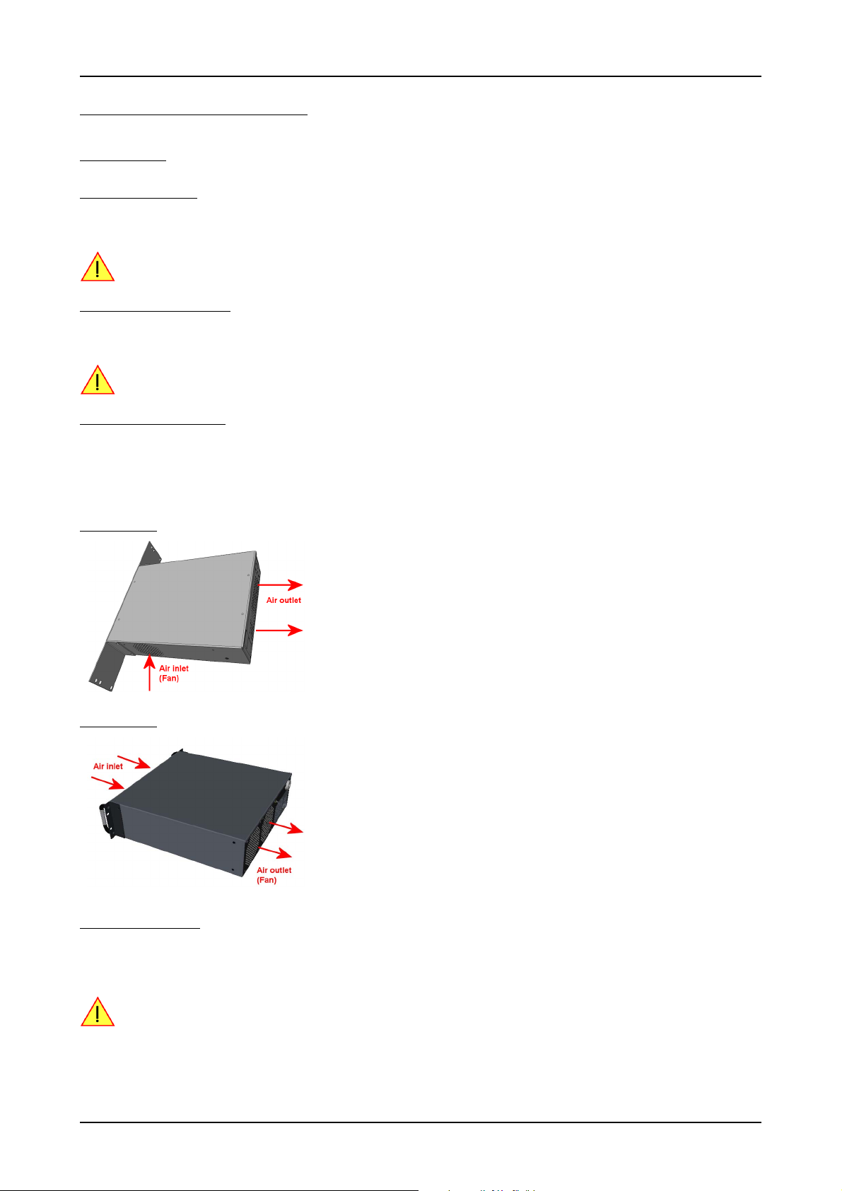
Warnings Hardware Installation
Hardware Installation
Warnings
ESD Precautions
The digitizerNETBOX/generatorNETBOX products internally contain electronic components that can be damaged by electrostatic discharge
(ESD). The grounded chassis itself gives a very good protection against ESD.
Before connecting signals to the digitizerNETBOX/generatorNETBOX it is recommended to bleed off any electrostatic electricity.
Opening the Chassis
There are no components inside the chassis that need any operating by the user. In contrary there are a lot of components that may be harmed
when operated unproperly by a use.
As Spectrum only gives a warranty on the complete instrument, opening the chassis will make you loose the
warranty.
Cooling Precautions
The high performance digitizers/generators of the digitizerNETBOX/generatorNETBOX operate with components having very high power
consumption. Therefore the digitizerNETBOX/generatorNETBOX models have sufficient cooling fans.
Make sure that the air inlets and air outlets are free and uncovered and in case of a DN6 ensure that the installed filters at the inlet are cleaned
regularly.
DN2 airflow:
DN6 airflow:
Sources of noise
The digitizerNETBOX/generatorNETBOX is using electrical components with very high resolution and high sensitivity. The signal inputs will
acquire your signals with a high quality but will also collect spurious noise signals from various sources - especially if using the inputs in high
impedance mode. To minimize this effect the cabeling must be made with care.
Keep away the cables from any sources that may inject noise into the signals like other instruments, crossing
or even worse running in parallel with other cables with high frequency signals on them. If possible use differential signalling to minimize the effectes of injected noise.
26 digitizerNETBOX DN2.44x Manual / DN6.44x Manual
Page 27
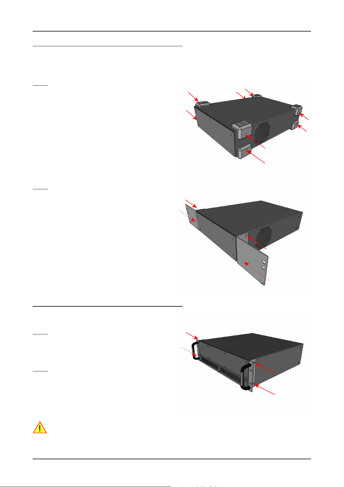
Hardware Installation Installing 19“ rack mount option for DN2
Installing 19“ rack mount option for DN2
This option is an extra that has to be ordered separately. It can be ordered with the digitizerNETBOX/generatorNETBOX from the beginning
or it can be ordered later on, if it is becomming necessary to mount the digitizerNETBOX/generatorNETBOX into a 19“ rack. In any case
the digitizerNETBOX/generatorNETBOX comes pre-configured as a standalone unit, which has to menually be converted to the rackmount
configuration by the user.
Step 1
The rackmount option comes with the required Torx T20 size screw driver to un-mount the default screws holding the bumper feet.
Unscrew these 8 Torx T20 screws with the provided screw driver and
keep them together with the un-mounted bumpers for possible later use
in case the rackmount option shall be un-mounted again in the future.
Step 2
Mount the 19“ rack mount extension using the four phillips-head screws
that are also provided with each rack mount extension. Two screws are
required for each rack mounting bracket.
Care should be taken to not overtighten the screws.
Installing 19“ rack mount option for DN6
Installing the rack mount extension for the DN6 series follows the same
principles as for the DN2 models shown above.
Step 1
Unscrew the existing bumper corner pieces with the provided screw
driver and keep them together with the un-mounted bumpers for possible later use in case the rackmount option shall be un-mounted again in
the future.
Step 2
Mount the 19“ rack mount extension using the four phillips-head screws
that are also provided with each rack mount extension. Two screws are
required for each rack mounting bracket. Care should be taken to not
overtighten the screws.
In addition to using the provided rack mount extension for fastening the DN6 device within the 19“ rack, the
user must take additional measures, suitable for the used rack, to provide adequate mechanical support at
the backside of the device.
This support is required for DN6 devices due to their higher weight compared to DN2 devices.
(c) Spectrum GmbH 27
Page 28
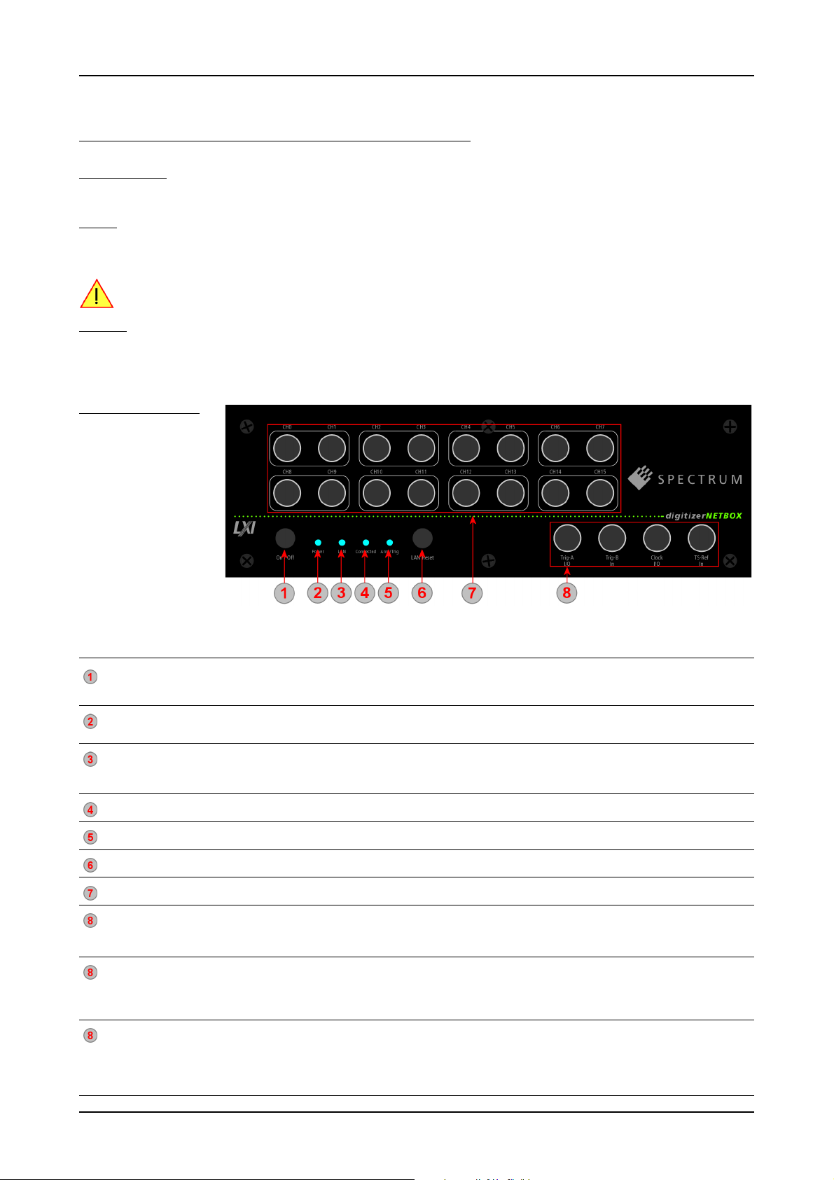
Setup of digitizerNETBOX/generatorNETBOX Hardware Installation
Setup of digitizerNETBOX/generatorNETBOX
Connections
First of all the digitizerNETBOX/generatorNETBOX needs to be connected to both power line and LAN environment:
Power
Connect the power line cable to a matching power source. First connect the cable to the digitizerNETBOX/generatorNETBOX, second connect the cable to the power plug. Please check the technical data section to see the requirements for the power supply.
If using a DC power option please be sure to have the external DC power source switched off while connecting the power lines. Only switch on the power supply after all connections have been done and are checked.
Ethernet
Connect the digitizerNETBOX/generatorNETBOX to either your company LAN or directly to your PC. Please use a standard Cat-5 Ethernet
cable for the connection. Alternatively an industrial screwed connection is also possible. Please see the technical data section for information
on the alternative connection type.
Front Panel DN2
The right-hand drawing
gives you an overview on
one digitizerNETBOX
DN2 front panel.
Depending on the version
of the digitizerNETBOX or
generatorNETBOX you
have the area 7 may differ
in terms of number of channels or grouping of the
channels.
In area 8 a version with
4 BNC connectors is
shown. Other versions with 5 SMA, 6 BNC or 7 SMA connectors are also available. Please see the table below for the different connections.
Area Name Status Description
Power On/Off press while device stopped digitizerNETBOX/generatorNETBOX is started
Power LED LED off no power connected to the device
LAN LED LED off no LAN connection
Connected LED LED off Device is not in use
Arm/Trigger LED off No trigger detected, device is waiting for trigger event, or not armed at all
LAN Reset press once Does a reset of the LAN settings to default state. The reset button needs to be pressed for 4 seconds to issue
Signal Connections Connect your input signals here. For differential connections use even channels for positive phase and odd
Control Connections
(4 BNC connector
version, for M2i module
based products)
Control Connections
(5 SMA connector
version, for M3i module
based products))
Control Connections
(6 BNC connector
version, for M2p module
based products))
short press while device is running digitizerNETBOX/generatorNETBOX is closing the embedded controller and is going into standby mode
long press while device is running digitizerNETBOX/generatorNETBOX is aborted and is going into standby. Please only use this stop method
LED orange power is connected, device is in standby mode
LED green device has started and is working
LED red Error while trying to get a LAN connection
LED green Device is connected to LAN.
LED green flashing Device is connected to LAN. Flashing indicates LAN ID (see webserver)
LED green Device is in use by other PC
LED green Trigger detected, acquisition is running or already finished
Trig-A I/O Trigger A with programmable input or output. This is the main external trigger
Trig-B In Trigger B, input only. This trigger is referenced in the manual as TRIG_XIO0
Clock I/O Clock with programmable input or output
TS-Ref In Timestamp Reference Clock Input
Clock In External clock input
Clock Out External clock output
Trig-A In Trigger A, input only. This is the main external trigger. The trigger line is reference in the manual as EXT0
Trig-B I/O Trigger B/Multi Purpose X0 with programmable direction. The connection is referenced in the manual as X0
TS_Ref In Timestamp Reference Clock Input
Clock In External clock input
Trig In Trigger, input only. This is the main external trigger. The trigger line is reference in the manual as EXT0
X0 Out Multi Purpose X0, output only. Clock output available. The connection is referenced in the manual as X0
X1 I/O Multi Purpose X1 with programmable direction. The connection is referenced in the manual as X1
X2 I/O Multi Purpose X2 with programmable direction. The connection is referenced in the manual as X2
X3 I/O Multi Purpose X3 with programmable direction. The connection is referenced in the manual as X3
if the digitizerNETBOX/generatorNETBOX is not responding
the reset. The reset command is then issued immediatley independent of the current run state of the device.
channels for negative phase.
28 digitizerNETBOX DN2.44x Manual / DN6.44x Manual
Page 29
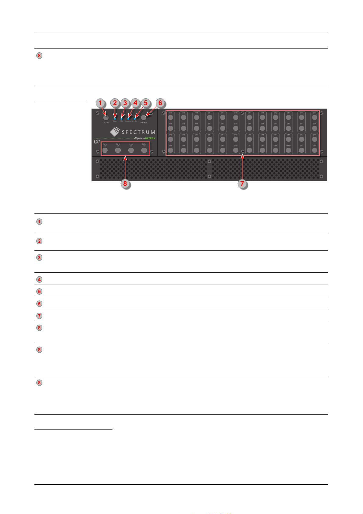
Hardware Installation Setup of digitizerNETBOX/generatorNETBOX
Area Name Status Description
Control Connections
(7 SMA connector
version, for M4i module
based products))
Clock In External clock input
Clock Out External clock output
Trig0 In Trigger 0, input only. This is the main external trigger. The trigger line is reference in the manual as EXT0
Trig1 In Trigger 1, input only. This is the secondary external trigger. This line is reference in the manual as EXT1
X0 I/O Multi Purpose X0 with programmable direction. The connection is referenced in the manual as X0
X1 I/O Multi Purpose X1 with programmable direction. The connection is referenced in the manual as X1
X2 I/O Multi Purpose X2 with programmable direction. The connection is referenced in the manual as X2
Front Panel DN6
The right-hand drawing
gives you an overview on
one digitizerNETBOX
DN6 front panel.
Depending on the version
of the digitizerNETBOX
or generatorNETBOX
you have, the area 7 may
differ in terms of number
of channels or grouping
of the channels.
In area 8 a version with
4 BNC connectors is
shown. Other versions
with 5 SMA, 6 BNC or 7 SMA connectors are also available. Please see the table below for the different connections.
Area Name Status Description
Power On/Off press while device stopped digitizerNETBOX/generatorNETBOX is started
Power LED LED off no power connected to the device
LAN LED LED off No LAN connection.
Connected LED LED off Device is not in use
Arm/Trigger LED off No trigger detected, device is waiting for trigger event, or not armed at all
LAN Reset press once Does a reset of the LAN settings to default state. The reset button needs to be pressed for 4 seconds to issue
Signal Connections Connect your input signals here. For differential connections use even channels for positive phase and odd
Control Connections
(4 BNC connector
version, for M2i module
based products)
Control Connections
(6 BNC connector
version, for M2p module
based products))
Control Connections
(7 SMA connector
version, for M4i module
based products)
short press while device is running digitizerNETBOX/generatorNETBOX is closing the embedded controller and is going into standby mode
long press while device is running digitizerNETBOX/generatorNETBOX is aborted and is going into standby. Please only use this stop method
LED orange power is connected, device is in standby mode
LED green device has started and is working
LED red Error while trying to get a LAN connection.
LED green Device is connected to LAN.
LED green flashing Device is connected to LAN. Flashing indicates LAN ID (see webserver).
LED green Device is in use by other PC
LED green Trigger detected, acquisition is running or already finished
Trig-A I/O Trigger A with programmable input or output. This is the main external trigger
Trig-B In Trigger B, input only. This trigger is referenced in the manual as TRIG_XIO0
Clock I/O Clock with programmable input or output
TS-Ref In Timestamp Reference Clock Input
Clock In External clock input
Trig In Trigger, input only. This is the main external trigger. The trigger line is reference in the manual as EXT0
X0 Out Multi Purpose X0, output only. Clock output available. The connection is referenced in the manual as X0
X1 I/O Multi Purpose X1 with programmable direction. The connection is referenced in the manual as X1
X2 I/O Multi Purpose X2 with programmable direction. The connection is referenced in the manual as X2
X3 I/O Multi Purpose X3 with programmable direction. The connection is referenced in the manual as X3
Clock In External clock input
Clock Out External clock output
Trig0 In Trigger 0, input only. This is the main external trigger. The trigger line is reference in the manual as EXT0
Trig1 In Trigger 1, input only. This is the secondary external trigger. This line is reference in the manual as EXT1
X0 I/O Multi Purpose X0 with programmable direction. The connection is referenced in the manual as X0
X1 I/O Multi Purpose X1 with programmable direction. The connection is referenced in the manual as X1
X2 I/O Multi Purpose X2 with programmable direction. The connection is referenced in the manual as X2
if the digitizerNETBOX/generatorNETBOX is not responding
the reset. The reset command is then issued immediatley independent of the current run state of the device.
channels for negative phase.
Ethernet Default Settings
The digitizerNETBOX/generatorNETBOX is started with the following Ethernet configuration:
Setting Default Setup
DHCP enabled
Auto IP enabled
Host Name Default hostname as netbox type + serial number Example: DN2_465-08_sn8085
(c) Spectrum GmbH 29
Page 30

Detecting the digitizerNETBOX Hardware Installation
Detecting the digitizerNETBOX
Before accessing the digitizerNETBOX/generatorNETBOX one has to determine the IP address of the digitizerNETBOX/generatorNETBOX.
Normally that can be done using one of the two methods described below:
Discovery Function
The digitizerNETBOX/generatorNETBOX responds to the VISA described Discovery function. The next chapter will show how to install and
use the Spectrum control center to execute the discovery function and to find the Spectrum hardware. As the discovery function is a standard
feature of all LXI devices there are other software packages that can find the digitizerNETBOX/generatorNETBOX using the discovery function:
• Spectrum control center (limited to Spectrum remote products)
• free LXI System Discovery Tool from the LXI consortium (www.lxistandard.org)
• Measurement and Automation Explorer from National Instrumen
• ts (NI MAX)
• Keysight Connection Expert from Keysight Technologies
Additionally the discovery procedure can also be started from ones own specific application:
#define TIMEOUT_DISCOVERY 5000 // timeout value in ms
const uint32 dwMaxNumRemoteCards = 50;
char* pszVisa[dwMaxNumRemoteCards] = { NULL };
char* pszIdn[dwMaxNumRemoteCards] = { NULL };
const uint32 dwMaxIdnStringLen = 256;
const uint32 dwMaxVisaStringLen = 50;
// allocate memory for string list
for (uint32 i = 0; i < dwMaxNumRemoteCards; i++)
{
pszVisa[i] = new char [dwMaxVisaStringLen];
pszIdn[i] = new char [dwMaxIdnStringLen];
memset (pszVisa[i], 0, dwMaxVisaStringLen);
memset (pszIdn[i], 0, dwMaxIdnStringLen);
}
// first make discovery - check if there are any LXI compatible remote devices
dwError = spcm_dwDiscovery ((char**)pszVisa, dwMaxNumRemoteCards, dwMaxVisaStringLen, TIMEOUT_DISCOVERY);
// second: check from which manufacturer the devices are
spcm_dwSendIDNRequest ((char**)pszIdn, dwMaxNumRemoteCards, dwMaxIdnStringLen);
// Use the VISA strings of these devices with Spectrum as manufacturer
// for accessing remote devices without previous knowledge of their IP address
Finding the digitizerNETBOX/generatorNETBOX in the network
As the digitizerNETBOX/generatorNETBOX is a standard network device it has its own IP address and host name and can be found in the
computer network. The standard host name consist of the model type and the serial number of the digitizerNETBOX/generatorNETBOX. The
serial number is also found on the type plate on the back of the digitizerNETBOX/generatorNETBOX chassis.
30 digitizerNETBOX DN2.44x Manual / DN6.44x Manual
Page 31

Hardware Installation Detecting the digitizerNETBOX
Windows 7, Windows 8, Windows 10
Under Windows 7, Windows 8 and
Windows 10 the digitizerNETBOX and
generatorNETBOX devices are listed under the
„other devices“ tree with their given host name.
A right click on the digitizerNETBOX or
generatorNETBOX device opens the properties
window where you find further information on the
device including the IP address.
From here it is possible to go the website of the
device where all necessary information are found
to access the device from software.
Troubleshooting
If the above methods do not work please try one of the following steps:
• Ask your network administrator for the IP address of the digitizerNETBOX/generatorNETBOX and access it directly over the IP address.
• Check your local firewall whether it allows access to the device and whether it allows to access the ports listed in the technical data section.
• Check with your network administrator whether the subnet, the device and the ports that are listed in the technical data section are accessible from your system due to company security settings.
(c) Spectrum GmbH 31
Page 32

Needed Software for operating Software Driver Installation
Software Driver Installation
Before using the digitizerNETBOX/generatorNETBOX a software package and the appropriate API drivers must be installed that matches the
operating system. The installation is done in different ways depending on the used operating system. The driver that is on CD supports all
products of the digitizerNETBOX/generatorNETBOX family as well as all cards of the M2i/M3i/M4i/M4x series. That means that you can
use the same driver for all products of these families.
Needed Software for operating
The digitizerNETBOX/generatorNETBOX comes fully installed and ready to start. However to operate the digitizerNETBOX or
generatorNETBOX from the client PC there need to be some software packages to be installed there:
Spectrum driver API
The Spectrum API is installed automatically under Windows when installing the Card Control Center. Under Linux it is necessary to install the
matching driver API for your Linux client system before installing the Card Control Center.
Spectrum Card Control Center
This software is the maintenance tool for all Spectrum products. In here the digitizerNETBOX/generatorNETBOX can be searched inside the
LAN (Discovery function), all hardware information is found, updates and product tests can be done. The Card Control Center and all of its
functions are explained in greater detail later on in this manual.
The card control center is available for Windows and Linux, both 32 bit and 64 bit (Windows 32 bit version runs on WOW64)
SBench 6
SBench 6 allows to operate the digitizerNETBOX/generatorNETBOX in all hardware modes, displays data, streams to hard disk and allows
to make calculations and exports. The digitizerNETBOX/generatorNETBOX is equipped with a full SBench 6 Professional license. Even if you
want to operate the digitizerNETBOX/generatorNETBOX from your self written software it is recommended that you install SBench 6 to do
first hardware tests and to validate your own software results with the software from the hardware manufacturer. For SBench 6 a dedicated
manual is installed with the software package.
SBench 6 is available for Windows and Linux, both 32 bit and 64 bit (Windows 32 bit version runs on WOW64)
Examples and Drivers
If you intend to operate the digitizerNETBOX/generatorNETBOX from a self written program, be it IVI based, C++, C#, LabVIEW, MATLAB
or something else, it is necessary to install the matching drivers and examples for the platform you want to run.
Location
The needed software for operating the digitizerNETBOX/generatorNETBOX can be found on three different locations. Please choose the one
most convinient for you.
Install software packages from CD
The CD that is delivered together with the digitizerNETBOX/generatorNETBOX contains the complete software and documentation package
that is available for your digitizerNETBOX/generatorNETBOX. You find the software packages at the following locations on the CD:
Software Package Operating System Location
Card Control Center Windows CD: \Install\Win
SBench 6 Windows CD: \Install\Win
LabVIEW, MATLAB, IVI Windows CD: \Install\Win
C++, C#, VB.NET, Delphi, Python, Java, LabWindows/CVI... Windows CD: \Examples\...
Driver API Linux CD: \Driver\linux\install_libonly.sh
Card Control Center Linux CD: \Install\Linux\SBench6
SBench 6 Linux CD: \Install\Linx\spcm_control_center
MATLAB (64bit only) Linux CD: \Install\Linux
C++, Python, Java Linux CD: \Examples\...
Install software packages from the internet
All software packages are found on the downlaod page under www.spectrum-instrumentation.com
Inhere the latest versions and updates are available.
Install software packages from the digitizerNETBOX/generatorNETBOX
For easy installation or for installation on machines that don’t have access to a CDROM drive all software packages are also available for
download directly from the digitizerNETBOX/generatorNETBOX.
Please go to the download page of the integrated webserver and download and execute the software packages.
32 digitizerNETBOX DN2.44x Manual / DN6.44x Manual
Page 33

Software Driver Installation Linux
Linux
Overview
The Spectrum M2i/M3i/M4i/M4x/M2p cards and digitizerNETBOX/generatorNETBOX products are delivered with Linux drivers suitable
for Linux installations based on kernel 2.4, 2.6, 3.x or 4.x, single processor (non-SMP) and SMP systems, 32 bit and 64 bit systems. As each
Linux distribution contains different kernel versions and different system setup it is in nearly every case necessary, to have a directly matching
kernel driver for card level products to run it on a specific system. For digitizerNETBOX/generatorNETBOX products the library is suffcient
and no kernel driver has to be installed.
Spectrum delivers pre-compiled kernel driver modules for a number of common distributions with the cards. You may try to use one of these
kernel modules for different distributions which have a similar kernel version. Unfortunately this won’t work in most cases as most Linux system
refuse to load a driver which is not exactly matching. In this case it is possible to get the kernel driver sources from Spectrum. Please contact
your local sales representative to get more details on this procedure.
The Standard delivery contains the pre-compiled kernel driver modules for the most popular Linux distributions, like Suse, Debian, Fedora and Ubuntu. The list with all pre-compiled and readily supported distributions and their respective kernel version can be found under:
http://spectrum-instrumentation.com/en/supported-linux-distributions
The Linux drivers have been tested with all above mentioned distributions by Spectrum. Each of these distributions has been installed with the default setup using no kernel updates. A lot more different distributions
are used by customers with self compiled kernel driver modules.
or via the shown QR code.
Standard Driver Installation
The driver is delivered as installable kernel modules together with libraries to access the kernel driver. The installation script will help you with
the installation of the kernel module and the library.
This installation is only needed if you are operating real locally installed cards. For software emulated demo
cards, remotely installed cards or for digitizerNETBOX/generatorNETBOX products it is only necessary to install the libraries as explained further below.
Login as root
It is necessary to have the root rights for installing a driver.
Call the install.sh <install_path> script
This script will install the kernel module and some helper scripts to a given directory. If you do not specify a directory it will use your home
directory as destination. It is possible to move the installed driver files later to any other directory.
The script will give you a list of matching kernel modules. Therefore it checks for the system width (32 bit or 64 bit) and the processor (single
or smp). The script will only show matching kernel modules. Select the kernel module matching your system. The script will then do the following steps:
• copy the selected kernel module to the install directory (spcm.o or spcm.ko)
• copy the helper scripts to the install directory (spcm_start.sh and spc_end.sh)
• copy and rename the matching library to /usr/lib (/usr/lib/libspcm_linux.so)
Udev support
Once the driver is loaded it automatically generates the device nodes under /dev. The cards are automatically named to /dev/spcm0,
/dev/spcm1,...
You may use all the standard naming and rules that are available with udev.
Start the driver
Starting the driver can be done with the spcm_start.sh script that has been placed in the install directory. If udev is installed the script will only
load the driver. If no udev is installed the start script will load the driver and make the required device nodes /dev/spcm0... for accessing
the drivers. Please keep in mind that you need root rights to load the kernel module and to make the device nodes!
Using the dedicated start script makes sure that the device nodes are matching your system setup even if new hardware and drivers have
been added in between. Background: when loading the device driver it gets assigned a „major“ number that is used to access this driver.
All device nodes point to this major number instead of the driver name. The major numbers are assigned first come first served. This means
that installing new hardware may result in different major numbers on the next system start.
(c) Spectrum GmbH 33
Page 34

Linux Software Driver Installation
Get first driver info
After the driver has been loaded successfully some information about the installed boards can be found in the /proc/spcm_cards file. Some
basic information from the on-board EEProm is listed for every card.
cat /proc/spcm_cards
Stop the driver
You may want to unload the driver and clean up all device nodes. This can be done using the spcm_end.sh script that has also been placed
in the install directory
Standard Driver Update
A driver update is done with the same commands as shown above. Please make sure that the driver has been stopped before updating it.
To stop the driver you may use the spcm_end.sh script.
Compilation of kernel driver sources (option)
The driver sources are only available for existing customers on special request and against a signed NDA. The driver sources are not part of
the standard delivery. The driver source package contains only the sources of the kernel module, not the sources of the library.
Please do the following steps for compilation and installation of the kernel driver module:
Login as root
It is necessary to have the root rights for installing a driver.
Call the compile script make_spcm_linux_kerneldrv.sh
This script will examine the type of system you use and compile the kernel with the correct settings. If using a kernel 2.4 the makefile expects
two symbolic links in your system:
• /usr/src/linux pointing to the correct kernel source directory
• /usr/src/linux/.config pointing to the currently used kernel configuration
The compile script will then automatically call the install script and install the just compiled kernel module in your home directory. The rest of
the installation procedure is similar as explained above.
Update of self compiled kernel driver
If the kernel driver has changed, one simply has to perform the same steps as shown above and recompile the kernel driver module. However
the kernel driver module isn’t changed very often.
Normally an update only needs new libraries. To update the libraries only you can either download the full Linux driver
(spcm_linux_drv_v123b4567) and only use the libraries out of this or one downloads the library package which is much smaller and doesn’t
contain the pre-compiled kernel driver module (spcm_linux_lib_v123b4567).
The update is done with a dedicated script which only updates the library file. This script is present in both driver archives:
sh install_libonly.sh
Library only
The kernel driver module only contains the basic hardware functions that are necessary to access locally installed card level products. The
main part of the driver is located inside a dynamically loadable library that is delivered with the driver. This library is available in 3 different
versions:
• spcm_linux_32bit_stdc++5.so - supporting libstdc++.so.5 on 32 bit systems
• spcm_linux_32bit_stdc++6.so - supporting libstdc++.so.6 on 32 bit systems
• spcm_linux_64bit_stdc++6.so - supporting libstdc++.so.6 on 64 bit systems
The matching version is installed automatically in the /usr/lib directory by the kernel driver install script for card level products. The library
is renamed for easy access to libspcm_linux.so.
For digitizerNETBOX/generatorNETBOX products and also for evaluating or using only the software simulated demo cards the library is installed with a separate install script:
sh install_libonly.sh
34 digitizerNETBOX DN2.44x Manual / DN6.44x Manual
Page 35

Software Driver Installation Linux
To access the driver library one must include the library in the compilation:
gcc -o test_prg -lspcm_linux test.cpp
To start programming the cards under Linux please use the standard C/C++ examples which are all running under Linux and Windows.
Control Center
The Spectrum Control Center is also available for Linux and needs to be installed separately. The features of the Control Center are described in a later chapter in deeper detail. The Control Center has been tested under all Linux distributions for which Spectrum
delivers pre-compiled kernel modules. The following packages need to be installed to run
the Control Center:
• X-Server
• expat
• freetype
• fontconfig
• libpng
• libspcm_linux (the Spectrum linux driver library)
Installation
Use the supplied packages in either *.deb or *.rpm format found in the driver section of
the CD by double clicking the package file root rights from a X-Windows window.
The Control Center is installed under KDE, Gnome or Unity in the system/system tools
section. It may be located directly in this menu or under a „More Programs“ menu. The
final location depends on the used Linux distribution. The program itself is installed as
/usr/bin/spcmcontrol and may be started directly from here.
Manual Installation
To manually install the Control Center, first extract the files from the rpm matching your distribution:
rpm2cpio spcmcontrol-{Version}.rpm > ~/spcmcontrol-{Version}.cpio
cd ~/
cpio -id < spcmcontrol-{Version}.cpio
You get the directory structure and the files contained in the rpm package. Copy the binary spcmcontrol to /usr/bin. Copy the .desktop file
to /usr/share/applications. Run ldconfig to update your systems library cache. Finally you can run spcmcontrol.
Troubleshooting
If you get a message like the following after starting spcmcontrol:
spcm_control: error while loading shared libraries: libz.so.1: cannot open shared object file: No such file
or directory
Run ldd spcm_control in the directory where spcm_control resides to see the dependencies of the program. The output may look like this:
libXext.so.6 => /usr/X11R6/lib/libXext.so.6 (0x4019e000)
libX11.so.6 => /usr/X11R6/lib/libX11.so.6 (0x401ad000)
libz.so.1 => not found
libdl.so.2 => /lib/libdl.so.2 (0x402ba000)
libpthread.so.0 => /lib/tls/libpthread.so.0 (0x402be000)
libstdc++.so.6 => /usr/lib/libstdc++.so.6 (0x402d0000)
As seen in the output, one of the libraries isn’t found inside the library cache of the system. Be sure that this library has been properly installed.
You may then run ldconfig. If this still doesn’t help please add the library path to /etc/ld.so.conf and run ldconfig again.
If the libspcm_linux.so is quoted as missing please make sure that you have installed the card driver properly before. If any other library is
stated as missing please install the matching package of your distribution.
(c) Spectrum GmbH 35
Page 36

Software Overview Software
Software
This chapter gives you an overview about the structure of the drivers and the software, where to find and how to use the examples. It shows
in detail, how the drivers are included using different programming languages and deals with the differences when calling the driver functions
from them.
This manual only shows the use of the standard driver API. For further information on programming drivers
for third-party software like LabVIEW, MATLAB or IVI an additional manual is required that is available on
CD or by download on the internet.
Software Overview
The Spectrum drivers offer you a common and fast API for using all of the board hardware features. This API is the same on all supported
operating systems. Based on this API one can write own programs using any programming language that can access the driver API. This
manual describes in detail the driver API, providing you with the necessary information to write your own programs.
The drivers for third-party products like LabVIEW or MATLAB are also based on this API. The special functionality of these drivers is not subject
of this document and is described with separate manuals available on the CD or on the website.
Card Control Center
A special card control center is available on CD and from the internet for all Spectrum M2i/M3i/M4i/M4x/M2p cards and for all digitizerNETBOX or
generatorNETBOX products. Windows users find the Control Center installer on the
CD under „Install\win\spcmcontrol_install.exe“.
Linux users find the versions for the different stdc++ libraries under /Install/linux/spcm_control_center/ as RPM packages.
When using a digitizerNETBOX/generatorNETBOX the Card Control Center installers for Windows and Linux are also directly available from the integrated webserver.
The Control Center under Windows and Linux is available as an executive program.
Under Windows it is also linked as a system control and can be accessed directly
from the Windows control panel. Under Linux it is also available from the KDE System Settings, the Gnome or Unity Control Center. The different functions of the Spectrum card control center are explained in detail in the
following passages.
To install the Spectrum Control Center you will need to be logged in with administrator rights for your operating system. On all Windows versions, starting with Windows Vista, installations with enabled UAC will ask
you to start the installer with administrative rights (run as administrator).
36 digitizerNETBOX DN2.44x Manual / DN6.44x Manual
Page 37

Software Card Control Center
Discovery of Remote Cards and digitizerNETBOX/generatorNETBOX products
The Discovery function helps you to find and identify the Spectrum LXI
instruments like digitizerNETBOX/generatorNETBOX available to
your computer on the network. The Discovery function will also locate
Spectrum card products handled by an installed Spectrum Remote
Server somewhere on the network. The function is not needed if you
only have locally installed cards.
Please note that only remote products are found that are currently not
used by another program. Therefore in a bigger network the number
of Spectrum products found may vary depending on the current usage
of the products.
Execute the Discovery function by pressing the „Discovery“ button.
There is no progress window shown. After the discovery function has
been executed the remotely found Spectrum products are listed under
the node Remote as separate card level products. Inhere you find all
hardware information as shown in the next topic and also the needed
VISA resource string to access the remote card.
Please note that these information is also stored on your system and
allows Spectrum software like SBench 6 to access the cards directly
once found with the Discovery function.
After closing the control center and re-opening it the previously found
remote products are shown with the prefix cached, only showing the
card type and the serial number. This is the stored information that allows other Spectrum products to access previously found cards. Using
the „Update cached cards“ button will try to re-open these cards and gather information of it. Afterwards the remote cards may disappear if
they’re in use from somewhere else or the complete information of the remote products is shown again.
Enter IP Address of digitizerNETBOX/generatorNETBOX manually
If for some reason an automatic discovery is not suitable, such as the case where the remote
device is located in a different subnet, it can also be manually acessed by its type and IP address.
Wake On LAN of digitizerNETBOX/generatorNETBOX
Cached digitizerNETBOX/generatorNETBOX products that are currently in standby mode can
be woken up by using the „Wake remote device“ entry from the context menu.
The Control Center will broadcast a standard Wake On LAN „Magic Packet“, that is sent to the
device’s MAC address.
It is also possible to use any other Wake On LAN software to wake a digitizerNETBOX by sending such a „Magic Packet“ to the MAC address, which must be then entered manually.
It is also possible to wake a digitizerNETBOX/generatorNETBOX from your own application
software by using the SPC_NETBOX_WAKEONLAN register. To wake a
digitizerNETBOX/generatorNETBOX with the MAC address „00:03:2d:20:48“, the following
command can be issued:
spcm_dwSetParam_i64 (NULL, SPC_NETBOX_WAKEONLAN, 0x00032d2048ec);
(c) Spectrum GmbH 37
Page 38

Card Control Center Software
Netbox Monitor
The Netbox Monitor permanently monitors whether the digitizerNETBOX/generatorNETBOX is still available through LAN. This tool is helpful
if the digitizerNETBOX is located somewhere in the company LAN or located remotely or directly mounted inside another device. Starting
the Netbox Monitor can be done in two different ways:
• Starting manually from the Spectrum Control Center using the context menu as shown above
• Starting from command line. The Netbox Monitor program is automatically installed together with the Spectrum Control Center and is
located in the selected install folder. Using the command line tool one can place a simple script into the autostart folder to have the Netbox Monitor running automatically after system boot. The command line tool needs the IP address of the
digitizerNETBOX/generatorNETBOX to monitor:
NetboxMonitor 192.168.169.22
The Netbox Monitor is shown as a small window with the type of digitizerNETBOX/generatorNETBOX in the title and the IP address under which it is accessed in the window itself. The Netbox Monitor runs completely independent of any other software and
can be used in parallel to any application software. The background of the IP address is used to display the current status of the
device. Pressing the Escape key or alt + F4 (Windows) terminates the Netbox Monitor permanently.
After starting the Netbox Monitor it is also displayed as a tray icon under Windows. The tray icon itself shows the status
of the digitizerNETBOX/generatorNETBOX as a color. Please note that the tray icon may be hidden as a Windows
default and need to be set to visible using the Windows tray setup.
Left clicking on the tray icon will hide/show the small Netbox Monitor status window. Right clicking on the tray icon as
shown in the picture on the right will open up a context menu. In here one can again select to hide/show the Netbox
Monitor status window, one can directly open the web interface from here or quit the program (including the tray icon)
completely.
The checkbox „Show Status Message“ controls whether the tray icon should emerge a status message on status change. If enabled (which is
default) one is notified with a status message if for example the LAN connection to the digitizerNETBOX/generatorNETBOX is lost.
The status colors:
• Green: digitizerNETBOX/generatorNETBOX available and accessible over LAN
• Cyan: digitizerNETBOX/generatorNETBOX is used from my computer
• Yellow: digitizerNETBOX/generatorNETBOX is used from a different computer
• Red: LAN connection failed, digitizerNETBOX/generatorNETBOX is no longer accessible
Hardware information
Through the control center you can easily get the main information
about all the installed Spectrum hardware. For each installed card
there is a separate tree of information available. The picture shows the
information for one installed card by example. This given information
contains:
• Basic information as the type of card, the production date and its
serial number, as well as the installed memory, the hardware revision of the base card, the number of available channels and
installed acquisition modules.
• Information about the maximum sampling clock and the available
quartz clock sources.
• The installed features/options in a sub-tree. The shown card is
equipped for example with the option Multiple Recording, Gated
Sampling, Timestamp and ABA-mode.
• Detailed Information concerning the installed acquisition modules.
In case of the shown analog acquisition card the information consists of the module’s hardware revision, of the converter resolution
and the last calibration date as well as detailed information on the
available analog input ranges, offset compensation capabilities
and additional features of the inputs.
38 digitizerNETBOX DN2.44x Manual / DN6.44x Manual
Page 39

Software Card Control Center
Firmware information
Another sub-tree is informing about the cards firmware version. As all Spectrum cards consist of several programmable
components, there is one firmware version per component.
Nearly all of the components firmware can be updated by
software. The only exception is the configuration device,
which only can receive a factory update.
The procedure on how to update the firmware of your Spectrum card with the help of the card control center is described
in a dedicated section later on.
The procedure on how to update the firmware of your
digitizerNETBOX/generatorNETBOX with the help of the integrated Webserver is described in a dedicated chapter later
on.
Software License information
This sub-tree is informing about installed possible software licenses.
As a default all cards come with the demo professional license of SBench6, that is limited to 30 starts of the software
with all professional features unlocked.
The number of demo starts left can be seen here.
(c) Spectrum GmbH 39
Page 40

Card Control Center Software
Driver information
The Spectrum card control center also offers a way to
gather information on the installed and used Spectrum
driver.
The information on the driver is available through a dedicated tab, as the picture is showing in the example.
The provided information informs about the used type,
distinguishing between Windows or Linux driver and the
32 bit or 64 bit type.
It also gives direct information about the version of the
installed Spectrum kernel driver, separately for M2i/ M3i
cards and M4i/M4x/M2p cards and the version of the
library (which is the *.dll file under Windows).
The information given here can also be found under
Windows using the device manager form the
control panel. For details in driver details within the control panel please stick to the section on driver installation
in your hardware manual.
Installing and removing Demo cards
With the help of the card control center one can install demo cards
in the system. A demo card is simulated by the Spectrum driver including data production for acquisition cards. As the demo card is
simulated on the lowest driver level all software can be tested including SBench, own applications and drivers for third-party products
like LabVIEW. The driver supports up to 64 demo cards at the same
time. The simulated memory as well as the simulated software options can be defined when adding a demo card to the system.
Please keep in mind that these demo cards are only meant to test software and to show certain abilities of the software. They do not simulate the complete behavior of a card, especially not any timing
concerning trigger, recording length or FIFO mode notification. The
demo card will calculate data every time directly after been called
and give it to the user application without any more delay. As the
calculation routine isn’t speed optimized, generating demo data
may take more time than acquiring real data and transferring them
to the host PC.
Installed demo cards are listed together with the real hardware in the main information tree as described above. Existing demo cards can be
deleted by clicking the related button. The demo card details can be edited by using the edit button. It is for example possible to virtually
install additional feature to one card or to change the type to test with a different number of channels.
For installing demo cards on a system without real hardware simply run the Control Center installer. If the
installer is not detecting the necessary driver files normally residing on a system with real hardware, it will
simply install the Spcm_driver.
Feature upgrade
All optional features of the M2i/M3i/M4i/M4x cards that do not require any
hardware modifications can be installed on fielded cards. After Spectrum has received the order, the customer will get a personalized upgrade code. Just start the
card control center, click on „install feature“ and enter that given code. After a
short moment the feature will be installed and ready to use. No restart of the host
system is required.
For details on the available options and prices please contact your local Spectrum
distributor.
40 digitizerNETBOX DN2.44x Manual / DN6.44x Manual
Page 41

Software Card Control Center
Software License upgrade
The software license for SBench 6 Professional is installed on the hardware. If ordering a software license for a card that has already been delivered you will get an upgrade code to install that software license. The upgrade code will only match for that
particular card with the serial number given in the license. To install the software license please click the „Install SW License“ button and type in the code exactly as
given in the license.
Performing card calibration
The card control center also provides an easy way to access the
automatic card calibration routines of the Spectrum A/D converter cards. Depending on the used card family this can affect offset
calibration only or also might include gain calibration. Please refer to the dedicated chapter in your hardware manual for details.
Performing memory test
The complete on-board memory of the Spectrum M2i/M3i/M4i/M4x/M2p
cards can be tested by the memory test included with the card control center.
When starting the test, randomized data is generated and written to the onboard memory. After a complete write cycle all the data is read back and compared with the generated pattern.
Depending on the amount of installed on-board memory, and your computer’s
performance this operation might take a while.
Transfer speed test
The control center allows to measure the bus transfer
speed of an installed Spectrum card. Therefore different
setup is run multiple times and the overall bus transfer
speed is measured. To get reliable results it is necessary
that you disable debug logging as shown above. It is also
highly recommended that no other software or time-consuming background threads are running on that system.
The speed test program runs the following two tests:
• Repetitive Memory Transfers: single DMA data transfers are repeated and measured. This test simulates
the measuring of pulse repetition frequency when
doing multiple single-shots. The test is done using different block sizes. One can estimate the transfer in
relation to the transferred data size on multiple single-shots.
• FIFO mode streaming: this test measures the streaming speed in FIFO mode. The test can only use the same direction of transfer the card
has been designed for (card to PC=read for all DAQ cards, PC to card=write for all generator cards and both directions for I/O cards).
The streaming speed is tested without using the front-end to measure the maximum bus speed that can be reached.
The Speed in FIFO mode depends on the selected notify size which is explained later in this manual in greater detail.
The results are given in MB/s meaning MByte per second. To estimate whether a desired acquisition speed is possible to reach one has to
calculate the transfer speed in bytes. There are a few things that have to be put into the calculation:
• 12, 14 and 16 bit analog cards need two bytes for each sample.
• 16 channel digital cards need 2 bytes per sample while 32 channel digital cards need 4 bytes and 64 channel digital cards need 8
bytes.
• The sum of analog channels must be used to calculate the total transfer rate.
• The figures in the Speed Test Utility are given as MBytes, meaning 1024 * 1024 Bytes, 1 MByte = 1048576 Bytes
As an example running a card with 2 14 bit analog channels with 28 MHz produces a transfer rate of [2 channels * 2 Bytes/Sample *
28000000] = 112000000 Bytes/second. Taking the above figures measured on a standard 33 MHz PCI slot the system is just capable of
reaching this transfer speed: 108.0 MB/s = 108 * 1024 * 1024 = 113246208 Bytes/second.
Unfortunately it is not possible to measure transfer speed on a system without having a Spectrum card installed.
(c) Spectrum GmbH 41
Page 42

Accessing the hardware with SBench 6 Software
Debug logging for support cases
For answering your support questions as fast as possible, the
setup of the card, driver and firmware version and other information is very helpful.
Therefore the card control center provides an easy way to
gather all that information automatically.
Different debug log levels are available through the graphical interface. By default the log level is set to „no logging“ for
maximum performance.
The customer can select different log levels and the path of
the generated ASCII text file. One can also decide to delete the previous log file first before creating a new one automatically or to append
different logs to one single log file.
For maximum performance of your hardware, please make sure that the debug logging is set to „no logging“ for normal operation. Please keep in mind that a detailed logging in append mode can quickly generate huge log files.
Device mapping
Within the „Device mapping“ tab of the Spectrum Control Center, one can enable the re-mapping of Spectrum devices, be it either local cards, remote instruments such as a digitizerNETBOX or generatorNETBOX or even cards in a
remote PC and accessed via the Spectrum remote server option.
In the left column the re-mapped device name is visible that is given to the device
in the right column with its original un-mapped device string.
In this example the two local cards „spcm0“ and „spcm1“ are re-mapped to
„spcm1“ and „spcm0“ respectively, so that their names are simply swapped.
The remote digitizerNETBOX device is mapped to spcm2.
The application software can then use the re-mapped name for simplicity instead
of the quite long VISA string.
Changing the order of devices within one group (either local cards or remote
devices) can simply be accomplished by draging&dropping the cards to their
desired position in the same table.
Accessing the hardware with SBench 6
After the installation of the cards and the drivers it can be useful to first test
the card function with a ready to run software before starting with programming. If accessing a digitizerNETBOX/generatorNETBOX a full SBench 6
Professional license is installed on the system and can be used without any
limitations. For plug-in card level products a base version of SBench 6 is delivered with the card on CD also including a 30 starts Professional demo
version for plain card products. If you already have bought a card prior to
the first SBench 6 release please contact your local dealer to get a SBench
6 Professional demo version.
SBench 6 supports all current acquisition and generation cards and digitizerNETBOX/generatorNETBOX products from Spectrum. Depending on the
used product and the software setup, one can use SBench as a digital storage oscilloscope, a spectrum analyzer, a logic analyzer or simply as a data
recording front end. Different export and import formats allow the use of
SBench 6 together with a variety of other programs.
On the CD you’ll find an install version of SBench 6 in the directory /Install/SBench6. The current version of SBench 6 is available free of charge
directly from the Spectrum website www.spectrum-instrumentation.com.
Please go to the download section and get the latest version there. If using
the digitizerNETBOX/generatorNETBOX, a SBench 6 version is also available on the webpages of the digitizerNETBOX/generatorNETBOX.
42 digitizerNETBOX DN2.44x Manual / DN6.44x Manual
Page 43

Software C/C++ Driver Interface
SBench 6 has been designed to run under Windows 7, Windows 8 and Windows 10 as well as Linux using KDE, Gnome or Unity Desktop.
C/C++ Driver Interface
C/C++ is the main programming language for which the drivers have been designed for. Therefore the interface to C/C++ is the best match.
All the small examples of the manual showing different parts of the hardware programming are done with C. As the libraries offer a standard
interface it is easy to access the libraries also with other programming languages like Delphi, Basic, Python or Java . Please read the following
chapters for additional information on this.
Header files
The basic task before using the driver is to include the header files that are delivered on CD together with the board. The header files are
found in the directory /Driver/c_header. Please don’t change them in any way because they are updated with each new driver version to
include the new registers and new functionality.
dlltyp.h Includes the platform specific definitions for data types and function declarations. All data types are based on these definitions. The use of this type definition
regs.h Defines all registers and commands which are used in the Spectrum driver for the different boards. The registers a board uses are described in the board spe-
spcm_drv.h Defines the functions of the used SpcM driver. All definitions are taken from the file dlltyp.h. The functions themselves are described below.
spcerr.h Contains all error codes used with the Spectrum driver. All error codes that can be given back by any of the driver functions are also described here briefly. The
file allows the use of examples and programs on different platforms without changes to the program source. The header file supports Microsoft Visual C++, Borland C++ Builder and GNU C/C++ directly. When using other compilers it might be necessary to make a copy of this file and change the data types according to this compiler.
cific part of the documentation. This header file is common for all cards. Therefore this file also contains a huge number of registers used on other card types
than the one described in this manual. Please stick to the manual to see which registers are valid for your type of card.
error codes and their meaning are described in detail in the appendix of this manual.
Example for including the header files:
// ----- driver includes ----#include "dlltyp.h" // 1st include
#include "regs.h" // 2nd include
#include "spcerr.h" // 3rd include
#include "spcm_drv.h" // 4th include
Please always keep the order of including the four Spectrum header files. Otherwise some or all of the functions do not work properly or compiling your program will be impossible!
General Information on Windows 64 bit drivers
After installation of the Spectrum 64 bit driver there are two general ways to access the hardware and to develop applications. If you’re going to develop a real 64 bit application it is necessary to access the 64 bit
driver dll (spcm_win64.dll) as only this driver dll is supporting the full 64 bit address range.
But it is still possible to run 32 bit applications or to develop 32 bit applications even under Windows 64 bit.
Therefore the 32 bit driver dll (spcm_win32.dll) is also installed in the system. The Spectrum SBench5 software
is for example running under Windows 64 bit using this driver. The 32 bit dll of course only offers the 32 bit
address range and is therefore limited to access only 4 GByte of memory. Beneath both drivers the 64 bit kernel driver is running.
Mixing of 64 bit application with 32 bit dll or vice versa is not possible.
Microsoft Visual C++ 6.0, 2005 and newer 32 Bit
Include Driver
The driver files can be directly included in Microsoft C++ by simply using the library file spcm_win32_msvcpp.lib that is delivered together
with the drivers. The library file can be found on the CD in the path /examples/c_cpp/c_header. Please include the library file in your Visual
C++ project as shown in the examples. All functions described below are now available in your program.
Examples
Examples can be found on CD in the path /examples/c_cpp. This directory includes a number of different examples that can be used with
any card of the same type (e.g. A/D acquisition cards, D/A acquisition cards). You may use these examples as a base for own programming
and modify them as you like. The example directories contain a running workspace file for Microsoft Visual C++ 6.0 (*.dsw) as well as project
files for Microsoft Visual Studio 2005 and newer (*.vcproj) that can be directly loaded or imported and compiled.
There are also some more board type independent examples in separate subdirectory. These examples show different aspects of the cards
like programming options or synchronization and can be combined with one of the board type specific examples.
As the examples are build for a card class there are some checking routines and differentiation between cards families. Differentiation aspects
can be number of channels, data width, maximum speed or other details. It is recommended to change the examples matching your card
(c) Spectrum GmbH 43
Page 44

C/C++ Driver Interface Software
type to obtain maximum performance. Please be informed that the examples are made for easy understanding and simple showing of one
aspect of programming. Most of the examples are not optimized for maximum throughput or repetition rates.
Microsoft Visual C++ 2005 and newer 64 Bit
Depending on your version of the Visual Studio suite it may be necessary to install some additional 64 bit components (SDK) on your system.
Please follow the instructions found on the MSDN for further information.
Include Driver
The driver files can be directly included in Microsoft C++ by simply using the library file spcm_win64_msvcpp.lib that is delivered together
with the drivers. The library file can be found on the CD in the path /examples/c_cpp/c_header. All functions described below are now
available in your program.
C++ Builder 32 Bit
Include Driver
The driver files can be easily included in C++ Builder by simply using the library file spcm_win32_bcppb.lib that is delivered together with
the drivers. The library file can be found on the CD in the path /examples/c_cpp/c_header. Please include the library file in your C++ Builder
project as shown in the examples. All functions described below are now available in your program.
Examples
The C++ Builder examples share the sources with the Visual C++ examples. Please see above chapter for a more detailed documentation of
the examples. In each example directory are project files for Visual C++ as well as C++ Builder.
Linux Gnu C/C++ 32/64 Bit
Include Driver
The interface of the linux drivers does not differ from the windows interface. Please include the spcm_linux.lib library in your makefile to have
access to all driver functions. A makefile may look like this:
COMPILER = gcc
EXECUTABLE = test_prg
LIBS = -lspcm_linux
OBJECTS = test.o\
test2.o
all: $(EXECUTABLE)
$(EXECUTABLE): $(OBJECTS)
$(COMPILER) $(CFLAGS) -o $(EXECUTABLE) $(LIBS) $(OBJECTS)
%.o: %.cpp
$(COMPILER) $(CFLAGS) -o $*.o -c $*.cpp
Examples
The Gnu C/C++ examples share the source with the Visual C++ examples. Please see above chapter for a more detailed documentation of
the examples. Each example directory contains a makefile for the Gnu C/C++ examples.
C++ for .NET
Please see the next chapter for more details on the .NET inclusion.
Other Windows C/C++ compilers 32 Bit
Include Driver
To access the driver, the driver functions must be loaded from the 32 bit driver DLL. Most compilers offer special tools to generate a matching
library (e.g. Borland offers the implib tool that generates a matching library out of the windows driver DLL). If such a tool is available it is
recommended to use it. Otherwise the driver functions need to be loaded from the dll using standard Windows functions. There is one example in the example directory /examples/c_cpp/dll_loading that shows the process.
Example of function loading:
hDLL = LoadLibrary ("spcm_win32.dll"); // Load the 32 bit version of the Spcm driver
pfn_spcm_hOpen = (SPCM_HOPEN*) GetProcAddress (hDLL, "_spcm_hOpen@4");
pfn_spcm_vClose = (SPCM_VCLOSE*) GetProcAddress (hDLL, "_spcm_vClose@4");
44 digitizerNETBOX DN2.44x Manual / DN6.44x Manual
Page 45

Software Driver functions
Other Windows C/C++ compilers 64 Bit
Include Driver
To access the driver, the driver functions must be loaded from the 64 bit the driver DLL. Most compilers offer special tools to generate a matching library (e.g. Borland offers the implib tool that generates a matching library out of the windows driver DLL). If such a tool is available it
is recommended to use it. Otherwise the driver functions need to be loaded from the dll using standard Windows functions. There is one
example in the example directory /examples/c_cpp/dll_loading that shows the process for 32 bit environments. The only line that needs to
be modified is the one loading the DLL:
Example of function loading:
hDLL = LoadLibrary ("spcm_win64.dll"); // Modified: Load the 64 bit version of the Spcm driver here
pfn_spcm_hOpen = (SPCM_HOPEN*) GetProcAddress (hDLL, "spcm_hOpen");
pfn_spcm_vClose = (SPCM_VCLOSE*) GetProcAddress (hDLL, "spcm_vClose");
National Instruments LabWindows/CVI
Include Drivers
To use the Spectrum driver under LabWindows/CVI it is necessary to first load the functions from the driver dll. Please use the library file
spcm_win32_cvi.lib to access the driver functions.
Examples
Examples for LabWindows/CVI can be found on CD in the directory /examples/cvi. Please mix these examples with the standard C/C++
examples to have access to all functions and modes of the cards.
Driver functions
The driver contains seven main functions to access the hardware.
Own types used by our drivers
To simplify the use of the header files and our examples with different platforms and compilers and to avoid any implicit type conversions we
decided to use our own type declarations. This allows us to use platform independent and universal examples and driver interfaces. If you
do not stick to these declarations please be sure to use the same data type width. However it is strongly recommended that you use our defined
type declarations to avoid any hard to find errors in your programs. If you’re using the driver in an environment that is not natively supported
by our examples and drivers please be sure to use a type declaration that represents a similar data width
Declaration Type Declaration Type
int8 8 bit signed integer (range from -128 to +127) uint8 8 bit unsigned integer (range from 0 to 255)
int16 16 bit signed integer (range from -32768 to 32767) uint16 16 bit unsigned integer (range from 0 to 65535)
int32 32 bit signed integer (range from -2147483648 to 2147483647) uint32 32 bit unsigned integer (range from 0 to 4294967295)
int64 64 bit signed integer (full range) uint64 64 bit unsigned integer (full range)
drv_handle handle to driver, implementation depends on operating system platform
Notation of variables and functions
In our header files and examples we use a common and reliable form of notation for variables and functions. Each name also contains the
type as a prefix. This notation form makes it easy to see implicit type conversions and minimizes programming errors that result from using
incorrect types. Feel free to use this notation form for your programs also-
Declaration Notation Declaration Notation
int8 byName (byte) uint8 cName (character)
int16 nName uint16 wName (word)
int32 lName (long) uint32 dwName (double word)
int64 llName (long long) uint64 qwName (quad word)
int32* plName (pointer to long) char szName (string with zero termination)
Function
spcm_hOpen
This function initializes and opens an installed card supporting the new SpcM driver interface. At the time of printing this manual this are all
cards of the M2i/M3i/M4i/M4x cards and digitizerNETBOX/generatorNETBOX devices. The function returns a handle that has to be used
for driver access. If the card can’t be found or the loading of the driver generated an error the function returns a NULL. When calling this
function all card specific installation parameters are read out from the hardware and stored within the driver. It is only possible to open one
device by one software as concurrent hardware access may be very critical to system stability. As a result when trying to open the same
device twice an error will be raised and the function returns NULL.
Function spcm_hOpen (const char* szDeviceName):
drv_handle _stdcall spcm_hOpen ( // tries to open the device and returns handle or error code
const char* szDeviceName); // name of the device to be opened
(c) Spectrum GmbH 45
Page 46

Driver functions Software
Under Linux the device name in the function call needs to be a valid device name. Please change the string according to the location of the
device if you don’t use the standard Linux device names. The driver is installed as default under /dev/spcm0, /dev/spcm1 and so on. The
kernel driver numbers the devices starting with 0.
Under Windows the only part of the device name that is used is the tailing number. The rest of the device name is ignored. Therefore to keep
the examples simple we use the Linux notation in all our examples. The tailing number gives the index of the device to open. The Windows
kernel driver numbers all devices that it finds on boot time starting with 0.
Example for local installed cards
drv_handle hDrv; // returns the handle to the opended driver or NULL in case of error
hDrv = spcm_hOpen ("/dev/spcm0"); // string to the driver to open
if (!hDrv)
printf (“open of driver failed\n”);
Example for digitizerNETBOX/generatorNETBOX and remote installed cards
drv_handle hDrv; // returns the handle to the opended driver or NULL in case of error
hDrv = spcm_hOpen ("TCPIP::192.168.169.14::INST0::INSTR");
if (!hDrv)
printf (“open of driver failed\n”);
If the function returns a NULL it is possible to read out the error description of the failed open function by simply passing this NULL to the error
function. The error function is described in one of the next topics.
Function spcm_vClose
This function closes the driver and releases all allocated resources. After closing the driver handle it is not possible to access this driver any
more. Be sure to close the driver if you don’t need it any more to allow other programs to get access to this device.
Function spcm_vClose:
void _stdcall spcm_vClose ( // closes the device
drv_handle hDevice); // handle to an already opened device
Example:
spcm_vClose (hDrv);
Function
spcm_dwSetParam
All hardware settings are based on software registers that can be set by one of the functions spcm_dwSetParam. These functions set a register
to a defined value or execute a command. The board must first be initialized by the spcm_hOpen function. The parameter lRegister must have
a valid software register constant as defined in regs.h. The available software registers for the driver are listed in the board specific part of
the documentation below. The function returns a 32 bit error code if an error occurs. If no error occurs the function returns ERR_OK, what is
zero.
Function spcm_dwSetParam
uint32 _stdcall spcm_dwSetParam_i32 ( // Return value is an error code
drv_handle hDevice, // handle to an already opened device
int32 lRegister, // software register to be modified
int32 lValue); // the value to be set
uint32 _stdcall spcm_dwSetParam_i64m ( // Return value is an error code
drv_handle hDevice, // handle to an already opened device
int32 lRegister, // software register to be modified
int32 lValueHigh, // upper 32 bit of the value. Containing the sign bit !
uint32 dwValueLow); // lower 32 bit of the value.
uint32 _stdcall spcm_dwSetParam_i64 ( // Return value is an error code
drv_handle hDevice, // handle to an already opened device
int32 lRegister, // software register to be modified
int64 llValue); // the value to be set
Example:
if (spcm_dwSetParam_i32 (hDrv, SPC_MEMSIZE, 16384) != ERR_OK)
printf (“Error when setting memory size\n”);
This example sets the memory size to 16 kSamples (16384). If an error occurred the example will show a short error message
46 digitizerNETBOX DN2.44x Manual / DN6.44x Manual
Page 47

Software Driver functions
Function spcm_dwGetParam
All hardware settings are based on software registers that can be read by one of the functions spcm_dwGetParam. These functions read an
internal register or status information. The board must first be initialized by the spcm_hOpen function. The parameter lRegister must have a
valid software register constant as defined in the regs.h file. The available software registers for the driver are listed in the board specific part
of the documentation below. The function returns a 32 bit error code if an error occurs. If no error occurs the function returns ERR_OK, what
is zero.
Function spcm_dwGetParam
uint32 _stdcall spcm_dwGetParam_i32 ( // Return value is an error code
drv_handle hDevice, // handle to an already opened device
int32 lRegister, // software register to be read out
int32* plValue); // pointer for the return value
uint32 _stdcall spcm_dwGetParam_i64m ( // Return value is an error code
drv_handle hDevice, // handle to an already opened device
int32 lRegister, // software register to be read out
int32* plValueHigh, // pointer for the upper part of the return value
uint32* pdwValueLow); // pointer for the lower part of the return value
uint32 _stdcall spcm_dwGetParam_i64 ( // Return value is an error code
drv_handle hDevice, // handle to an already opened device
int32 lRegister, // software register to be read out
int64* pllValue); // pointer for the return value
Example:
int32 lSerialNumber;
spcm_dwGetParam_i32 (hDrv, SPC_PCISERIALNO, &lSerialNumber);
printf (“Your card has serial number: %05d\n”, lSerialNumber);
The example reads out the serial number of the installed card and prints it. As the serial number is available under all circumstances there is
no error checking when calling this function.
Different call types of spcm_dwSetParam and spcm_dwGetParam: _i32, _i64, _i64m
The three functions only differ in the type of the parameters that are used to call them. As some of the registers can exceed the 32 bit integer
range (like memory size or post trigger) it is recommended to use the _i64 function to access these registers. However as there are some
programs or compilers that don’t support 64 bit integer variables there are two functions that are limited to 32 bit integer variables. In case
that you do not access registers that exceed 32 bit integer please use the _i32 function. In case that you access a register which exceeds 64
bit value please use the _i64m calling convention. Inhere the 64 bit value is split into a low double word part and a high double word part.
Please be sure to fill both parts with valid information.
If accessing 64 bit registers with 32 bit functions the behavior differs depending on the real value that is currently located in the register.
Please have a look at this table to see the different reactions depending on the size of the register:
Internal register read/write Function type Behavior
32 bit register read spcm_dwGetParam_i32 value is returned as 32 bit integer in plValue
32 bit register read spcm_dwGetParam_i64 value is returned as 64 bit integer in pllValue
32 bit register read spcm_dwGetParam_i64m value is returned as 64 bit integer, the lower part in plValueLow, the upper part in plValueHigh. The upper part can
32 bit register write spcm_dwSetParam_i32 32 bit value can be directly written
32 bit register write spcm_dwSetParam_i64 64 bit value can be directly written, please be sure not to exceed the valid register value range
32 bit register write spcm_dwSetParam_i64m 32 bit value is written as llValueLow, the value llValueHigh needs to contain the sign extension of this value. In case
64 bit register read spcm_dwGetParam_i32 If the internal register has a value that is inside the 32 bit integer range (-2G up to (2G - 1)) the value is returned
64 bit register read spcm_dwGetParam_i64 value is returned as 64 bit integer value in pllValue independent of the value of the internal register.
64 bit register read spcm_dwGetParam_i64m the internal value is split into a low and a high part. As long as the internal value is within the 32 bit range, the low
64 bit register write spcm_dwSetParam_i32 the value to be written is limited to 32 bit range. If a value higher than the 32 bit range should be written, one of
64 bit register write spcm_dwSetParam_i64 the value has to be split into two parts. Be sure to fill the upper part lValueHigh with the correct sign extension even
64 bit register write spcm_dwSetParam_i64m the value can be written directly independent of the size.
be ignored as it’s only a sign extension
of llValueLow being a value >= 0 llValueHigh can be 0, in case of llValueLow being a value < 0, llValueHigh has to
be -1.
normally. If the internal register exceeds this size an error code ERR_EXCEEDSINT32 is returned. As an example:
reading back the installed memory will work as long as this memory is < 2 GByte. If the installed memory is >= 2
GByte the function will return an error.
part plValueLow contains the 32 bit value and the upper part plValueHigh can be ignored. If the internal value
exceeds the 32 bit range it is absolutely necessary to take both value parts into account.
the other function types need to used.
if you only write a 32 bit value as the driver every time interprets both parts of the function call.
Function
spcm_dwGetContBuf
This function reads out the internal continuous memory buffer in bytes, in case one has been allocated. If no buffer has been allocated the
function returns a size of zero and a NULL pointer. You may use this buffer for data transfers. As the buffer is continuously allocated in memory
(c) Spectrum GmbH 47
Page 48

Driver functions Software
the data transfer will speed up by up to 15% - 25%, depending on your specific kind of card. Please see further details in the appendix of
this manual.
uint32 _stdcall spcm_dwGetContBuf_i64 ( // Return value is an error code
drv_handle hDevice, // handle to an already opened device
uint32 dwBufType, // type of the buffer to read as listed above under SPCM_BUF_XXXX
void** ppvDataBuffer, // address of available data buffer
uint64* pqwContBufLen); // length of available continuous buffer
uint32 _stdcall spcm_dwGetContBuf_i64m (// Return value is an error code
drv_handle hDevice, // handle to an already opened device
uint32 dwBufType, // type of the buffer to read as listed above under SPCM_BUF_XXXX
void** ppvDataBuffer, // address of available data buffer
uint32* pdwContBufLenH, // high part of length of available continuous buffer
uint32* pdwContBufLenL); // low part of length of available continuous buffer
These functions have been added in driver version 1.36. The functions are not available in older driver versions.
These functions also only have effect on locally installed cards and are neither useful nor usable with any
digitizerNETBOX or generatorNETBOX products, because no local kernel driver is involved in such a setup.
For remote devices these functions will return a NULL pointer for the buffer and 0 Bytes in length.
Function
spcm_dwDefTransfer
The spcm_dwDefTransfer function defines a buffer for a following data transfer. This function only defines the buffer, there is no data transfer
performed when calling this function. Instead the data transfer is started with separate register commands that are documented in a later
chapter. At this position there is also a detailed description of the function parameters.
Please make sure that all parameters of this function match. It is especially necessary that the buffer address is a valid address pointing to
memory buffer that has at least the size that is defined in the function call. Please be informed that calling this function with non valid parameters may crash your system as these values are base for following DMA transfers.
The use of this function is described in greater detail in a later chapter.
Function spcm_dwDefTransfer
uint32 _stdcall spcm_dwDefTransfer_i64m(// Defines the transfer buffer by 2 x 32 bit unsigned integer
drv_handle hDevice, // handle to an already opened device
uint32 dwBufType, // type of the buffer to define as listed above under SPCM_BUF_XXXX
uint32 dwDirection, // the transfer direction as defined above
uint32 dwNotifySize, // no. of bytes after which an event is sent (0=end of transfer)
void* pvDataBuffer, // pointer to the data buffer
uint32 dwBrdOffsH, // high part of offset in board memory
uint32 dwBrdOffsL, // low part of offset in board memory
uint32 dwTransferLenH, // high part of transfer buffer length
uint32 dwTransferLenL); // low part of transfer buffer length
uint32 _stdcall spcm_dwDefTransfer_i64 (// Defines the transfer buffer by using 64 bit unsigned integer values
drv_handle hDevice, // handle to an already opened device
uint32 dwBufType, // type of the buffer to define as listed above under SPCM_BUF_XXXX
uint32 dwDirection, // the transfer direction as defined above
uint32 dwNotifySize, // no. of bytes after which an event is sent (0=end of transfer)
void* pvDataBuffer, // pointer to the data buffer
uint64 qwBrdOffs, // offset for transfer in board memory
uint64 qwTransferLen); // buffer length
This function is available in two different formats as the spcm_dwGetParam and spcm_dwSetParam functions are. The background is the
same. As long as you’re using a compiler that supports 64 bit integer values please use the _i64 function. Any other platform needs to use
the _i64m function and split offset and length in two 32 bit words.
Example:
int16* pnBuffer = new int16[8192];
if (spcm_dwDefTransfer_i64 (hDrv, SPCM_BUF_DATA, SPCM_DIR_CARDTOPC, 0, (void*) pnBuffer, 0, 16384) != ERR_OK)
printf (“DefTransfer failed\n”);
The example defines a data buffer of 8 kSamples of 16 bit integer values = 16 kByte (16384 byte) for a transfer from card to PC memory.
As notify size is set to 0 we only want to get an event when the transfer has finished.
Function spcm_dwInvalidateBuf
The invalidate buffer function is used to tell the driver that the buffer that has been set with spcm_dwDefTransfer call is no longer valid. It is
necessary to use the same buffer type as the driver handles different buffers at the same time. Call this function if you want to delete the buffer
memory after calling the spcm_dwDefTransfer function. If the buffer already has been transferred after calling spcm_dwDefTransfer it is not
necessary to call this function. When calling spcm_dwDefTransfer any further defined buffer is automatically invalidated.
48 digitizerNETBOX DN2.44x Manual / DN6.44x Manual
Page 49

Software Driver functions
Function spcm_dwInvalidateBuf
uint32 _stdcall spcm_dwInvalidateBuf ( // invalidate the transfer buffer
drv_handle hDevice, // handle to an already opened device
uint32 dwBufType); // type of the buffer to invalidate as
// listed above under SPCM_BUF_XXXX
Function spcm_dwGetErrorInfo
The function returns complete error information on the last error that has occurred. The error handling itself is explained in a later chapter in
greater detail. When calling this function please be sure to have a text buffer allocated that has at least ERRORTEXTLEN length. The error text
function returns a complete description of the error including the register/value combination that has raised the error and a short description
of the error details. In addition it is possible to get back the error generating register/value for own error handling. If not needed the buffers
for register/value can be left to NULL.
Note that the timeout event (ERR_TIMEOUT) is not counted as an error internally as it is not locking the driver
but as a valid event. Therefore the GetErrorInfo function won’t return the timeout event even if it had occurred
in between. You can only recognize the ERR_TIMEOUT as a direct return value of the wait function that was
called.
Function spcm_dwGetErrorInfo
uint32 _stdcall spcm_dwGetErrorInfo_i32 (
drv_handle hDevice, // handle to an already opened device
uint32* pdwErrorReg, // address of the error register (can be zero if not of interest)
int32* plErrorValue, // address of the error value (can be zero if not of interest)
char pszErrorTextBuffer[ERRORTEXTLEN]); // text buffer for text error
Example:
char szErrorBuf[ERRORTEXTLEN];
if (spcm_dwSetParam_i32 (hDrv, SPC_MEMSIZE, -1))
{
spcm_dwGetErrorInfo_i32 (hDrv, NULL, NULL, szErrorBuf);
printf (“Set of memsize failed with error message: %s\n”, szErrorBuf);
}
(c) Spectrum GmbH 49
Page 50

Delphi (Pascal) Programming Interface Software
Delphi (Pascal) Programming Interface
Driver interface
The driver interface is located in the sub-directory d_header and contains the following files. The files need to be included in the delphi project
and have to be put into the „uses“ section of the source files that will access the driver. Please do not edit any of these files as they’re regularly
updated if new functions or registers have been included.
file spcm_win32.pas
The file contains the interface to the driver library and defines some needed constants and variable types. All functions of the delphi library
are similar to the above explained standard driver functions:
// ----- device handling functions ----function spcm_hOpen (strName: pchar): int32; stdcall; external 'spcm_win32.dll' name '_spcm_hOpen@4';
procedure spcm_vClose (hDevice: int32); stdcall; external 'spcm_win32.dll' name '_spcm_vClose@4';
function spcm_dwGetErrorInfo_i32 (hDevice: int32; var lErrorReg, lErrorValue: int32; strError: pchar): uint32;
stdcall; external 'spcm_win32.dll' name '_spcm_dwGetErrorInfo_i32@16'
// ----- register access functions ----function spcm_dwSetParam_i32 (hDevice, lRegister, lValue: int32): uint32;
stdcall; external 'spcm_win32.dll' name '_spcm_dwSetParam_i32@12';
function spcm_dwSetParam_i64 (hDevice, lRegister: int32; llValue: int64): uint32;
stdcall; external 'spcm_win32.dll' name '_spcm_dwSetParam_i64@16';
function spcm_dwGetParam_i32 (hDevice, lRegister: int32; var plValue: int32): uint32;
stdcall; external 'spcm_win32.dll' name '_spcm_dwGetParam_i32@12';
function spcm_dwGetParam_i64 (hDevice, lRegister: int32; var pllValue: int64): uint32;
stdcall; external 'spcm_win32.dll' name '_spcm_dwGetParam_i64@12';
// ----- data handling ----function spcm_dwDefTransfer_i64 (hDevice, dwBufType, dwDirection, dwNotifySize: int32; pvDataBuffer: Pointer;
llBrdOffs, llTransferLen: int64): uint32;
stdcall; external 'spcm_win32.dll' name '_spcm_dwDefTransfer_i64@36';
function spcm_dwInvalidateBuf (hDevice, lBuffer: int32): uint32;
stdcall; external 'spcm_win32.dll' name '_spcm_dwInvalidateBuf@8';
The file also defines types used inside the driver and the examples. The types have similar names as used under C/C++ to keep the examples
more simple to understand and allow a better comparison.
file SpcRegs.pas
The SpcRegs.pas file defines all constants that are used for the driver. The constant names are the same names as used under the C/C++
examples. All constants names will be found throughout this hardware manual when certain aspects of the driver usage are explained. It is
recommended to only use these constant names for better visibility of the programs:
const SPC_M2CMD = 100; { write a command }
const M2CMD_CARD_RESET = $00000001; { hardware reset }
const M2CMD_CARD_WRITESETUP = $00000002; { write setup only }
const M2CMD_CARD_START = $00000004; { start of card (including writesetup) }
const M2CMD_CARD_ENABLETRIGGER = $00000008; { enable trigger engine }
...
file SpcErr.pas
The SpeErr.pas file contains all error codes that may be returned by the driver.
Including the driver files
To use the driver function and all the defined constants it is necessary to include the files into the project as
shown in the picture on the right. The project overview is taken from one of the examples delivered on CD.
Besides including the driver files in the project it is also necessary to include them in the uses section of the
source files where functions or constants should be used:
uses
Windows, Messages, SysUtils, Classes, Graphics, Controls, Forms, Dialogs,
StdCtrls, ExtCtrls,
SpcRegs, SpcErr, spcm_win32;
50 digitizerNETBOX DN2.44x Manual / DN6.44x Manual
Page 51

Software Delphi (Pascal) Programming Interface
Examples
Examples for Delphi can be found on CD in the directory /examples/delphi. The directory contains the above mentioned delphi header files
and a couple of universal examples, each of them working with a certain type of card. Please feel free to use these examples as a base for
your programs and to modify them in any kind.
spcm_scope
The example implements a very simple scope program that makes single acquisitions on button pressing. A fixed setup is done inside the
example. The spcm_scope example can be used with any analog data acquisition card from Spectrum. It covers cards with 1 byte per sample
(8 bit resolution) as well as cards with 2 bytes per sample (12, 14 and 16 bit resolution)
The program shows the following steps:
• Initialization of a card and reading of card information like type, function and serial number
• Doing a simple card setup
• Performing the acquisition and waiting for the end interrupt
• Reading of data, re-scaling it and displaying waveform on screen
(c) Spectrum GmbH 51
Page 52

Visual Basic Programming Interface and Examples Software
Visual Basic Programming Interface and Examples
Driver interface
The driver interface is located in the sub-directory b_header and contains the following files. The files need to be included in the basic project.
Please do not edit any of these files as they’re regularly updated if new functions or registers have been included.
file spcm_win32_decl.bas
The file contains the interface to the driver library and defines some needed constants. All functions of the visual basic library are similar to
the above explained standard driver functions:
' ----- card handling functions ----Public Declare Function spcm_hOpen Lib "spcm_win32.dll" Alias "_spcm_hOpen@4"
(ByVal szDeviceName As String) As Long
Public Declare Function spcm_vClose Lib "spcm_win32.dll" Alias "_spcm_vClose@4"
(ByVal hDevice As Long) As Long
Public Declare Function spcm_dwGetErrorInfo_i32 Lib "spcm_win32.dll" Alias "_spcm_dwGetErrorInfo_i32@16"
(ByVal hDevice As Long, ByRef lErrorReg, ByRef lErrorValue, ByVal szErrorText As String) As Long
' ----- software register handling ----Public Declare Function spcm_dwGetParam_i32 Lib "spcm_win32.dll" Alias "_spcm_dwGetParam_i32@12"
(ByVal hDevice As Long, ByVal lRegister As Long, ByRef lValue As Long) As Long
Public Declare Function spcm_dwGetParam_i64m Lib "spcm_win32.dll" Alias "_spcm_dwGetParam_i64m@16"
(ByVal hDevice As Long, ByVal lRegister As Long, ByRef lValueHigh As Long, ByRef lValueLow As Long) As Long
Public Declare Function spcm_dwSetParam_i32 Lib "spcm_win32.dll" Alias "_spcm_dwSetParam_i32@12"
(ByVal hDevice As Long, ByVal lRegister As Long, ByVal lValue As Long) As Long
Public Declare Function spcm_dwSetParam_i64m Lib "spcm_win32.dll" Alias "_spcm_dwSetParam_i64m@16"
(ByVal hDevice As Long, ByVal lRegister As Long, ByVal lValueHigh As Long, ByVal lValueLow As Long) As Long
' ----- data handling ----Public Declare Function spcm_dwDefTransfer_i64m Lib "spcm_win32.dll" Alias "_spcm_dwDefTransfer_i64m@36"
(ByVal hDevice As Long, ByVal dwBufType As Long, ByVal dwDirection As Long, ByVal dwNotifySize As Long, ByRef
pvDataBuffer As Any, ByVal dwBrdOffsH As Long, ByVal dwBrdOffsL As Long, ByVal dwTransferLenH As Long, ByVal
dwTransferLenL As Long) As Long
Public Declare Function spcm_dwInvalidateBuf Lib "spcm_win32.dll" Alias "_spcm_dwInvalidateBuf@8"
(ByVal hDevice As Long, ByVal lBuffer As Long) As Long
file SpcRegs.bas
The SpcRegs.bas file defines all constants that are used for the driver. The constant names are the same names as used under the C/C++
examples. All constants names will be found throughout this hardware manual when certain aspects of the driver usage are explained. It is
recommended to only use these constant names for better visibility of the programs:
Public Const SPC_M2CMD = 100 ' write a command
Public Const M2CMD_CARD_RESET = &H1& ' hardware reset
Public Const M2CMD_CARD_WRITESETUP = &H2& ' write setup only
Public Const M2CMD_CARD_START = &H4& ' start of card (including writesetup)
Public Const M2CMD_CARD_ENABLETRIGGER = &H8& ' enable trigger engine
...
file SpcErr.bas
The SpcErr.bas file contains all error codes that may be returned by the driver.
Including the driver files
To use the driver function and all the defined constants it is necessary to include the files into the
project as shown in the picture on the right. The project overview is taken from one of the examples
delivered on CD.
52 digitizerNETBOX DN2.44x Manual / DN6.44x Manual
Page 53

Software Visual Basic Programming Interface and Examples
Examples
Examples for Visual Basic can be found on CD in the directory /examples/basic. The directory contains the above mentioned basic header
files and a couple of universal examples, each of them working with a certain type of card. Please feel free to use these examples as a base
for your programs and to modify them in any kind.
spcm_scope
The example implements a very simple scope program that makes single acquisitions on button pressing. A fixed setup is done inside the
example. The spcm_scope example can be used with any analog data acquisition card from Spectrum. It covers cards with 1 byte per sample
(8 bit resolution) as well as cards with 2 bytes per sample (12, 14 and 16 bit resolution)
The program shows the following steps:
• Initialization of a card and reading of card information like type, function and serial number
• Doing a simple card setup
• Performing the acquisition and waiting for the end interrupt
• Reading of data, re-scaling it and displaying waveform on screen
(c) Spectrum GmbH 53
Page 54

.NET programming languages Software
.NET programming languages
Library
For using the driver with a .NET based language Spectrum delivers a special library that encapsulates the driver in a .NET object. By adding
this object to the project it is possible to access all driver functions and constants from within your .NET environment.
There is one small console based example for each supported .NET language that shows how to include the driver and how to access the
cards. Please combine this example with the different standard examples to get the different card functionality.
Declaration
The driver access methods and also all the type, register and error declarations are combined in the object Spcm and are located in one of
the two DLLs either SpcmDrv32.NET.dll or SpcmDrv64.NET.dll delivered with the .NET examples.
For simplicity, either file is simply called „SpcmDrv.NET.dll“ in the following passages and the actual file
name must be replaced with either the 32bit or 64bit version according to your application.
Spectrum also delivers the source code of the DLLs as a C# project. These sources are located in the directory SpcmDrv.NET.
namespace Spcm
{
public class Drv
{
[DllImport("spcm_win32.dll")]public static extern IntPtr spcm_hOpen (string szDeviceName);
[DllImport("spcm_win32.dll")]public static extern void spcm_vClose (IntPtr hDevice);
...
public class CardType
{
public const int TYP_M2I2020 = unchecked ((int)0x00032020);
public const int TYP_M2I2021 = unchecked ((int)0x00032021);
public const int TYP_M2I2025 = unchecked ((int)0x00032025);
...
public class Regs
{
public const int SPC_M2CMD = unchecked ((int)100);
public const int M2CMD_CARD_RESET = unchecked ((int)0x00000001);
public const int M2CMD_CARD_WRITESETUP = unchecked ((int)0x00000002);
...
Using C#
The SpcmDrv.NET.dll needs to be included within the Solution Explorer in the References section. Please use right mouse and select
„AddReference“. After this all functions and constants of the driver object are available.
Please see the example in the directory CSharp as a start:
// ----- open card ----hDevice = Drv.spcm_hOpen("/dev/spcm0");
if ((int)hDevice == 0)
{
Console.WriteLine("Error: Could not open card\n");
return 1;
}
// ----- get card type ----dwErrorCode = Drv.spcm_dwGetParam_i32(hDevice, Regs.SPC_PCITYP, out lCardType);
dwErrorCode = Drv.spcm_dwGetParam_i32(hDevice, Regs.SPC_PCISERIALNR, out lSerialNumber);
Example for digitizerNETBOX/generatorNETBOX and remotely installed cards:
// ----- open remote card ----hDevice = Drv.spcm_hOpen("TCPIP::192.168.169.14::INST0::INSTR");
54 digitizerNETBOX DN2.44x Manual / DN6.44x Manual
Page 55

Software .NET programming languages
Using Managed C++/CLI
The SpcmDrv.NET.dll needs to be included within the project options. Please select „Project“ - „Properties“ - „References“ and finally
„Add new Reference“. After this all functions and constants of the driver object are available.
Please see the example in the directory CppCLR as a start:
// ----- open card ----hDevice = Drv::spcm_hOpen("/dev/spcm0");
if ((int)hDevice == 0)
{
Console::WriteLine("Error: Could not open card\n");
return 1;
}
// ----- get card type ----dwErrorCode = Drv::spcm_dwGetParam_i32(hDevice, Regs::SPC_PCITYP, lCardType);
dwErrorCode = Drv::spcm_dwGetParam_i32(hDevice, Regs::SPC_PCISERIALNR, lSerialNumber);
Example for digitizerNETBOX/generatorNETBOX and remotely installed cards:
// ----- open remote card ----hDevice = Drv::spcm_hOpen("TCPIP::192.168.169.14::INST0::INSTR");
Using VB.NET
The SpcmDrv.NET.dll needs to be included within the project options. Please select „Project“ - „Properties“ - „References“ and finally
„Add new Reference“. After this all functions and constants of the driver object are available.
Please see the example in the directory VB.NET as a start:
' ----- open card ----hDevice = Drv.spcm_hOpen("/dev/spcm0")
If (hDevice = 0) Then
Console.WriteLine("Error: Could not open card\n")
Else
' ----- get card type ---- dwError = Drv.spcm_dwGetParam_i32(hDevice, Regs.SPC_PCITYP, lCardType)
dwError = Drv.spcm_dwGetParam_i32(hDevice, Regs.SPC_PCISERIALNR, lSerialNumber)
Example for digitizerNETBOX/generatorNETBOX and remotely installed cards:
' ----- open remote card ----hDevice = Drv.spcm_hOpen("TCPIP::192.168.169.14::INST0::INSTR")
Using J#
The SpcmDrv.NET.dll needs to be included within the Solution Explorer in the References section. Please use right mouse and select „AddReference“. After this all functions and constants of the driver object are available.
Please see the example in the directory JSharp as a start:
// ----- open card ----hDevice = Drv.spcm_hOpen("/dev/spcm0");
if (hDevice.ToInt32() == 0)
System.out.println("Error: Could not open card\n");
else
{
// ----- get card type ---- dwErrorCode = Drv.spcm_dwGetParam_i32(hDevice, Regs.SPC_PCITYP, lCardType);
dwErrorCode = Drv.spcm_dwGetParam_i32(hDevice, Regs.SPC_PCISERIALNR, lSerialNumber);
Example for digitizerNETBOX/generatorNETBOX and remotely installed cards:
' ----- open remote card ----hDevice = Drv.spcm_hOpen("TCPIP::192.168.169.14::INST0::INSTR")
(c) Spectrum GmbH 55
Page 56

Python Programming Interface and Examples Software
Python Programming Interface and Examples
Driver interface
The driver interface contains the following files. The files need to be included in the python project. Please do not edit any of these files as
they are regularily updated if new functions or registers have been included. To use pyspcm you need either python 2 (2.4, 2.6 or 2.7) or
python 3 (3.x) and ctype, which is included in python 2.6 and newer and needs to be installed separately for Python 2.4.
file pyspcm.py
The file contains the interface to the driver library and defines some needed constants. All functions of the python library are similar to the
above explained standard driver functions and use ctypes as input and return parameters:
# ----- Windows ----spcmDll = windll.LoadLibrary ("c:\\windows\\system32\\spcm_win32.dll")
# load spcm_hOpen
spcm_hOpen = getattr (spcmDll, "_spcm_hOpen@4")
spcm_hOpen.argtype = [c_char_p]
spcm_hOpen.restype = drv_handle
# load spcm_vClose
spcm_vClose = getattr (spcmDll, "_spcm_vClose@4")
spcm_vClose.argtype = [drv_handle]
spcm_vClose.restype = None
# load spcm_dwGetErrorInfo
spcm_dwGetErrorInfo_i32 = getattr (spcmDll, "_spcm_dwGetErrorInfo_i32@16")
spcm_dwGetErrorInfo_i32.argtype = [drv_handle, ptr32, ptr32, c_char_p]
spcm_dwGetErrorInfo_i32.restype = uint32
# load spcm_dwGetParam_i32
spcm_dwGetParam_i32 = getattr (spcmDll, "_spcm_dwGetParam_i32@12")
spcm_dwGetParam_i32.argtype = [drv_handle, int32, ptr32]
spcm_dwGetParam_i32.restype = uint32
# load spcm_dwGetParam_i64
spcm_dwGetParam_i64 = getattr (spcmDll, "_spcm_dwGetParam_i64@12")
spcm_dwGetParam_i64.argtype = [drv_handle, int32, ptr64]
spcm_dwGetParam_i64.restype = uint32
# load spcm_dwSetParam_i32
spcm_dwSetParam_i32 = getattr (spcmDll, "_spcm_dwSetParam_i32@12")
spcm_dwSetParam_i32.argtype = [drv_handle, int32, int32]
spcm_dwSetParam_i32.restype = uint32
# load spcm_dwSetParam_i64
spcm_dwSetParam_i64 = getattr (spcmDll, "_spcm_dwSetParam_i64@16")
spcm_dwSetParam_i64.argtype = [drv_handle, int32, int64]
spcm_dwSetParam_i64.restype = uint32
# load spcm_dwSetParam_i64m
spcm_dwSetParam_i64m = getattr (spcmDll, "_spcm_dwSetParam_i64m@16")
spcm_dwSetParam_i64m.argtype = [drv_handle, int32, int32, int32]
spcm_dwSetParam_i64m.restype = uint32
# load spcm_dwDefTransfer_i64
spcm_dwDefTransfer_i64 = getattr (spcmDll, "_spcm_dwDefTransfer_i64@36")
spcm_dwDefTransfer_i64.argtype = [drv_handle, uint32, uint32, uint32, c_void_p, uint64, uint64]
spcm_dwDefTransfer_i64.restype = uint32
spcm_dwInvalidateBuf = getattr (spcmDll, "_spcm_dwInvalidateBuf@8")
spcm_dwInvalidateBuf.argtype = [drv_handle, uint32]
spcm_dwInvalidateBuf.restype = uint32
# ----- Linux ----# use cdll because all driver access functions use cdecl calling convention under linux
spcmDll = cdll.LoadLibrary ("libspcm_linux.so")
# the loading of the driver access functions is similar to windows:
# load spcm_hOpen
spcm_hOpen = getattr (spcmDll, "spcm_hOpen")
spcm_hOpen.argtype = [c_char_p]
spcm_hOpen.restype = drv_handle
# ...
56 digitizerNETBOX DN2.44x Manual / DN6.44x Manual
Page 57

Software Python Programming Interface and Examples
file regs.py
The regs.py file defines all constants that are used for the driver. The constant names are the same names compared to the C/C++ examples.
All constant names will be found throughout this hardware manual when certain aspects of the driver usage are explained. It is recommended
to only use these constant names for better readability of the programs:
SPC_M2CMD = 100l # write a command
M2CMD_CARD_RESET = 0x00000001l # hardware reset
M2CMD_CARD_WRITESETUP = 0x00000002l # write setup only
M2CMD_CARD_START = 0x00000004l # start of card (including writesetup)
M2CMD_CARD_ENABLETRIGGER = 0x00000008l # enable trigger engine
...
file spcerr.py
The spcerr.py file contains all error codes that may be returned by the driver.
Examples
Examples for Python can be found on CD in the directory /examples/python. The directory contains the above mentioned header files and
some examples, each of them working with a certain type of card. Please feel free to use these examples as a base for your programs and
to modify them in any kind.
When allocating the buffer for DMA transfers, use the following function to get a mutable character buffer:
ctypes.create_string_buffer(init_or_size[, size])
(c) Spectrum GmbH 57
Page 58

Java Programming Interface and Examples Software
Java Programming Interface and Examples
Driver interface
The driver interface contains the following Java files (classes). The files need to be included in your Java project. Please do not edit any of
these files as they are regularily updated if new functions or registers have been included. The driver interface uses the Java Native Access
(JNA) library.
This library is licensed under the LGPL (https://www.gnu.org/licenses/lgpl-3.0.en.html) and has also to be included to your Java project.
To download the latest jna.jar package and to get more information about the JNA project please check the projects GitHub page under:
https://github.com/java-native-access/jna
The following files can be found in the „SpcmDrv“ folder of your Java examples install path.
SpcmDrv32.java / SpcmDrv64.java
The files contain the interface to the driver library and defines some needed constants. All functions of the driver interface are similar to the
above explained standard driver functions. Use the SpcmDrv32.java for 32 bit and the SpcmDrv64.java for 64 bit projects:
...
public interface SpcmWin64 extends StdCallLibrary {
SpcmWin64 INSTANCE = (SpcmWin64)Native.loadLibrary (("spcm_win64"), SpcmWin64.class);
int spcm_hOpen (String sDeviceName);
void spcm_vClose (int hDevice);
int spcm_dwSetParam_i64 (int hDevice, int lRegister, long llValue);
int spcm_dwGetParam_i64 (int hDevice, int lRegister, LongByReference pllValue);
int spcm_dwDefTransfer_i64 (int hDevice, int lBufType, int lDirection, int lNotifySize,
Pointer pDataBuffer, long llBrdOffs, long llTransferLen);
int spcm_dwInvalidateBuf (int hDevice, int lBufType);
int spcm_dwGetErrorInfo_i32 (int hDevice, IntByReference plErrorReg,
IntByReference plErrorValue, Pointer sErrorTextBuffer);
}
...
SpcmRegs.java
The SpcmRegs class defines all constants that are used for the driver. The constants names are the same names compared to the C/C++
examples. All constant names will be found throughout this hardware manual when certain aspects of the driver usage are explained. It is
recommended to only use these constant names for better readability of the programs:
...
public static final int SPC_M2CMD = 100;
public static final int M2CMD_CARD_RESET = 0x00000001;
public static final int M2CMD_CARD_WRITESETUP = 0x00000002;
public static final int M2CMD_CARD_START = 0x00000004;
public static final int M2CMD_CARD_ENABLETRIGGER = 0x00000008;
...
SpcmErrors.java
The SpcmErrors class contains all error codes that may be returned by the driver.
Examples
Examples for Java can be found on CD in the directory /examples/java. The directory contains the above mentioned header files and some
examples, each of them working with a certain type of card. Please feel free to use these examples as a base for your programs and to modify
them in any kind.
58 digitizerNETBOX DN2.44x Manual / DN6.44x Manual
Page 59

Software LabVIEW driver and examples
LabVIEW driver and examples
A full set of drivers and examples is available for LabVIEW for Windows. LabVIEW for Linux is currently not supported. The LabVIEW drivers have their own
manual. The LabVIEW drivers, examples and the manual are found on the CD
that has been included in the delivery. The latest version is also available on our
webpage www.spectrum-instrumentation.com
Please follow the description in the LabVIEW manual for installation and useage
of the LabVIEW drivers for this card.
MATLAB driver and examples
A full set of drivers and examples is available for Mathworks MATLAB for Windows (32 bit
and 64 bit versions) and also for MATLAB for Linux (64 bit version). There is no additional
toolbox needed to run the MATLAB examples and drivers.
The MATLAB drivers have their own manual. The MATLAB drivers, examples and the manual
are found on the CD that has been included in the delivery. The latest version is also available on our webpage www.spectrum-instrumentation.com
Please follow the description in the MATLAB manual for installation and useage of the MATLAB drivers for this card.
(c) Spectrum GmbH 59
Page 60

Integrated Webserver
Integrated Webserver
The digitizerNETBOX/generatorNETBOX has an integrated webserver following the LXI standards. The web pages give informtion about the
device, allows to set up ethernet details or make firmware updates.
The webserver can be reached in three different ways:
• Directly by typing the IP address into the URL field of a Web Browser.
• By selecting it from the Spectrum Control Center via the context menu on the remote device node (as shown on
the screen shot on the right).
• On Windows machines (starting with Windows 7) on the device properties page, as described in the section
„Finding the digitizerNETBOX in the network“ earlier in this manual.
Home Screen
The home screen gives an overview about the instrument
showing all main information:
Name Description
Instrument Model The specific model code of your digitizerNETBOX or
Manufacturer Manufacturer of the device - Spectrum GmbH
Serial Number The unique serial number of the product. The serial
Description A free definable description of the specific device that you
LXI Features Listing the supported LXI features
LXI Version Listing the used LXI specification for designing this device
Host Name The host name given by the DNS server. If the DNS server
mDNS Host Name The internal mDNS host name which allows to find the
MAC Address The unique MAC address of the device which can also be
TCP/IP Address The current TCP/IP address as given by the DNS
Firmware revision The revision of the installed firmware files for the digitizerNETBOX/generatorNETBOX itself. The integrated digitizer modules have their own firmware versioning
Software Revision The software revision of the integrated remote server software
Instrument Address
String (VISA)
LAN ID Indicator Pressing this button starts flashing the LAN LED light on the front plate of the device. This helps to find the device inside a 19“ rack where the back of the device
generatorNETBOX
number is also found on the type plate on the back of the
chassis of the digitizerNETBOX/generatorNETBOX.
can edit by yourself in the LAN configuration page. It is
recommended to include the location of the device and
any other infoamtion that helps your network administrator.
does not generate a host name, the IP address is shown
device in the network environment. The mDNS host name
can also be changed in the LAN configuration page
found on the type plate on the back of the device
and can be read out by the Spectrum control center
The instrument address string following the VISA notification. Using this address string one can access the digitizerNETBOX/generatorNETBOX from the software.
The integrated digitizer modules are numbered starting with INST0 (example: TCPIP::192.168.169.14::INST0::INSTR)
with the type plate is not easily accessible.
LAN Configuration
The LAN configuration page allows to change the LAN configuration of the device. This page is password protected if a
password is given in the security page.
Name Description
Host Name The offical host name as given by the DNS
mDNS Host Name The local host name which can be changed here
Domain The domain in which the digitizerNETBOX is placed if the
Description The device description which can be changed here
DHCP DHCP (Dynamic Host Configuration Protocol) setting
IP Address The current IP address as given by the DHCP server (DHCP enable) or entered manually
Subnet Mask The current subnet mask as given by the DHCP server (DHCP enable) or entered manually
Default Gateway The current default gateway address as given by the DHCP server (DHCP enable) or entered manually
DNS Server(s) The current DNS server address as given by the DHCP server (DHCP enable) or entered manually
As default DHCP (IPv4) will be used and an IP address will be automatically set. In case no DHCP server is found, an IP vill be obtained using
the AutoIP feature. This will lead to an IPv4 address of 169.254.x.y (with x and y being assigned to a free IP in the network) using a subnet
mask of 255.255.0.0.
The default IP setup can also be restored, by using the „LAN Reset“ button on the device.
If a fixed IP address should be used instead, the parameters need to be set according to the current LAN requirements.
60 digitizerNETBOX DN2.44x Manual / DN6.44x Manual
DNS server has filled this information correctly
Page 61

Integrated Webserver
Pressing the „edit configuration“ button will issue a new edit
page. If a password is given in the security pages the password must be entered before the edit screen is available
Name Description
Host Name Enter a new host name for the mDNS host name. Please
Domain The domain in which the
Submit Button After review this button submits the changes and changes
Reset Button Discards the changes and returns host name and descrip-
note that host names can only contain letters, numbers,
minus and underscore, no dots or blanks are allowed
digitizerNETBOX/generatorNETBOX is placed
host name and description permanently
tion to the previous values.
TCP/IP Mode Select between DHCP + AutoIP to have all configuration
IP Address Only available if manual TCP/IP mode is selected
Subnet Mask Only available if manual TCP/IP mode is selected
Default Gateway Only available if manual TCP/IP mode is selected
DNS Server(s) Only available if manual TCP/IP mode is selected
Submit Button Submits the changes. If you set the IP details manually please be sure that your device is adressable within your network. In case of a failure the LAN reset button
Reset Button Discards the changes and returns IP settings to the previous values
done automatically or Manual to enter all IP related settings manual.
on the front page of the device will set back the LAN configuration to DHCP
Status
Shows the internal device status. For each internal digitizer
module the status whether the module is available or locked
by a user is shown. A digitizer module is locked as soon as it
is opened from any software on any PC.
In case the instrument is locked, the IP address of the current
control PC can be obtained here.
Also the current temperature will be displayed here.
DN6.xxxx models of the digitizerNETBOX will also display
the case fan speed here as well (not shown on screen shot).
Security
Allows to set a password to protect the device from changes.
The password secures access to LAN configuration, power settings like reboot or power down and firmware updates of the
instrument. As default no password is set for the configuration.
To change the password the old password has to be entered
once and the new password twice to avoid typing errors.
In case of a lost password the LAN reset button on the front
plate of the digitizerNETBOX/generatorNETBOX will delete
the password and set the complete device to the default stage
again.
Documentation
All related documents for the device that may be needed to
operate the digitizerNETBOX/generatorNETBOX or to program it are available by download as pdf documents from
here.
(c) Spectrum GmbH 61
Page 62

Firmware Update
The complete firmware of the device can be updated with a
single firmware update file which is available for download
directly here by clicking the „check online“ button or on the
Spectrum webpage www.spectrum-instrumentation.com. The
firmware file contains update files for the following parts:
• firmware files of the integrated digitizer/generator
modules
• drivers for the digitizer/generator modules
• software and setup of the underlying operating system
• webserver and integrated web pages and manuals
• remote server software
• initialization scripts and tools
Power
From here the digitizerNETBOX/generatorNETBOX can be
remotely shut down or remotely rebooted. Please make sure
that no software is currently accessing the digitizerNETBOX
or generatorNETBOX before using any of these power options.
Integrated Webserver
Downloads
The websever gives access to all necessary software components for download. All these software installers are also
available on the CD that is delivered with the
digitizerNETBOX/generatorNETBOX and on the internet.
Logging
This is a debug setting only. You shouldn’t change any of these
settings unless our support team requested you to do so. Operating the digitizerNETBOX/generatorNETBOX with log-level
„Log all“ will slow down the operation as each single call is
logged as a text entry in the internal log file.
These debug log settings are similar to the ones described in the
chapter about the Spectrum control center. Using this logging
the internal communication between the remote server and the
locally installed Spectrum driver is logged.
Please note that some digitizerNETBOX/generatorNETBOX
products (having only one internal digitizer/generator installed) show an error message
„KernelOpen /dev/spcm1 failed“. This error message is not an
error but simply the remote server trying to open the second internal digitizer that isn’t installed.
62 digitizerNETBOX DN2.44x Manual / DN6.44x Manual
Page 63

Integrated Webserver
Access
In here it is possible to restrict the access to the
digitizerNETBOX/generatorNETBOX to certain IP addresses.
As long as the access list is clear, everybody who has a TCP/IP
connection to the digitizerNETBOX/generatorNETBOX can get
control of it and use it with any software like SBench 6.
Use the add IP to list field with the submit button to add an IP
address to the list. As a default your current IP address is shown
in the entry field.
After having setup an access list everybody else who is not on
the access restricted IP list can still see the digitizerNETBOX or
generatorNETBOX in the network and use the discovery function but access to the internal digitizers is restricted and no longer possible.
Use this option together with the password option to completely secure the digitizerNETBOX/generatorNETBOX from unwanted access.
Embedded Server
The embedded server is an option and is only available if ordered with and installed on your particular digitizerNETBOX/generatorNETBOX. Please see the dedicated Embedded
Server Option chapter for more information on this feature.
Using the „Reset password“ button the password for the user
„embedded“ is reset to the default password which is also „embedded“
The autostart feature allows the user to automatically start
scripts, programs or services on the device during boot process. If something fails with the start, the autostart feature can
be disabled using the „Autostart [Disable]“ button. After fixing the automatically starting programs one can enable the autostart feature again.
Login/Logout
As soon as a password has been entered in the security settings a login/logout command is available from the webpage
menu.
After entering the password once the login stays valid until a
logout or until closing the web browser.
(c) Spectrum GmbH 63
Page 64

About IVI IVI Driver
IVI Driver
The IVI Foundation is an open consortium founded in 1998 to promote standards for programming test instruments. Composed primarily of
instrument manufacturers, end-users, software vendors, and system integrators, the Foundation strives to create specifications that govern the
development of instrument drivers.
-> http://IVIfoundation.org
About IVI
The IVI standards define an open driver architecture, a set of instrument classes, and shared software components. Together these provide
critical elements needed for instrument interchangeability.
Benefits
IVI offers several benefits to measurement system designers:
• IVI's defined Application Programming Interfaces (APIs) standardize common measurement functions reducing the time needed to learn a
new IVI instrument.
• Instrument simulation allows developers to run code without an instrument. This feature reduces the need for sometimes scarce measurement hardware resources and it can simplify testing of measurement applications.
• IVI drivers feature enhanced ease of use in popular Application Development Environments. IVI's standard APIs, combined with IVI driver
wrappers where appropriate, provide fast, intuitive access to driver functions.
• IVI drivers provide for interchangeability. Interchangeability reduces the time and effort needed to integrate measurement devices into
new or existing systems
Interchangeability
Systems designed with IVI drivers enjoy the benefits of standardized code that can be interchanged into other systems. This code also supports
interchange of measurement devices -- helping to prevent hardware obsolescence. Interchangeability is supported on three levels: The IVI
architecture specifications allow architectural interchangeability -- that is a standard driver architecture that can be reused. The class specifications provide syntactic interchangeability which supports instrument exchange with minimal code changes. The highest level of interchangeability is achieved by using the IVI signal specifications.
General Concept of the Spectrum IVI driver
The Spectrum IVI driver is based on the standard Spectrum API and can be used with any Spectrum products specified below in the supported
hardware chapter. The Spectrum products to be accessed with the IVI driver can be locally installed data acquisition cards, remotely installed
data acquisition cards or remote LXI instruments like a digitizerNETBOX or generatorNETBOX.
64 digitizerNETBOX DN2.44x Manual / DN6.44x Manual
Page 65

IVI Driver Supported Spectrum Hardware
Supported Spectrum Hardware
All Spectrum analog data acquisition hardware based on the SPCM driver structure is supported by the IVI driver. There is only one IVI driver
for all hardware.
Supported data acquisition card families:
• M2i.20xx and M2i.20xx-exp family
• M3i.21xx and M3i.21xx-exp family
• M4i.22xx-x8 and M4x.22xx-x4 family
• M2i.30xx and M2i.30xx-exp family
• M2i.31xx and M2i.31xx-exp family
• M3i.32xx and M3i.32xx-exp family
• M2i.40xx and M2i.40xx-exp family
• M3i.41xx and M3i.41xx-exp family
• M4i.44xx-x8 and M4x.44xx-x4 family
• M2i.46xx and M2i.46xx-exp family
• M2i.47xx and M2i.47xx-exp family
• M3i.48xx and M3i.48xx-exp family
• M2i.49xx and M2i.49xx-exp family
• M2p.59xx-x4
• M2i.60xx and M2i.60xx-exp family
• M4i.66xx-x8 and M4x.66xx-x4 family
Supported digitizerNETBOX families
• DN2.20x-xx family
• DN2.22x-xx and DN6.22x-xx family
• DN2.44x-xx and DN6.44x-xx family
• DN2.46x-xx and DN6.46x-xx family
• DN2.49x-xx and DN6.49x-xx family
• DN2.59x-xx and DN6.59x-xx family
Supported generatorNETBOX families
• DN2.60x-xx family
• DN2.66x-xx and DN6.66x family
IVI Compliance
General information on the Spectrum IVI driver:
IVI class specification version Version 3.3
IVI-C interface supported
IVI-COM interface supported
IVI.NET interface not supported
The following IVI classes are supported by different instrument types:
IVI Class Supported by Spectrum hardware IVI specific driver function prefix
IVIScope Supported by all digitizerNETBOX devices and analog data
IVIDigitizer Supported by all digitizerNETBOX devices and analog data
IVIFgen Supported by all generatorNETBOX devices and analog data
acquisition cards listed above
acquisition cards listed above
generator cards listed above
SpecScope_
SpecDigitizer_
SpecFGen_
Supported Operating Systems
32 bit operating systems 64 bit operating systems
Winodws 7 Windows 7
Windows 8 Windows 8
Windows 10 Windows 10
(c) Spectrum GmbH 65
Page 66

IVI Compliance IVI Driver
Supported Standard Driver Features
Feature Supported Description of the Feature
State caching yes
Range checking yes
Instrument Status Checking yes
Multithread Safety yes IVI drivers are multithread safe. Multithread safety means that multiple threads in the same process can use
Simulation yes If simulation is enabled, an IVI specific driver does not perform instrument I/O, and the driver creates
standard feature of the API
which is permanently active
standard feature of the API
which is permanently active
standard feature of the API
which is permanently active
To minimize the number of I/O calls needed to configure an instrument to a new state, IVI specific drivers
may implement state caching. IVI specific drivers can choose to implement state caching for all, some, or
none of the instrument settings. If the user enables state caching and the IVI specific driver implements
caching for hardware configuration attributes, driver functions perform instrument I/O when the current state
of the instrument settings is different from what the user requests.
If range checking is enabled, an IVI specific driver checks that input parameters are within the valid range for
the instrument.
If instrument status checking is enabled, an IVI specific driver automatically checks the status of the
instrument after most operations. If the instrument indicates that it has an error, the driver returns a special
error code. The user then calls the Error Query function to retrieve the instrument specific error code from the
instrument.
the same IVI driver session and that different sessions of the same IVI driver can run simultaneously on
different threads.
simulated data for output parameters. This allows the user to execute instrument driver calls in the application
program even though the instrument is not available.
IVIScope Supported Class Capabilities
Feature Supported Description of Feature
IVIScopeBase yes Base Capabilities of the IVIScope specification. This group includes the capability to acquire waveforms using edge triggering.
IVIScopeInterpolation no Extension: IVIScope with the ability to configure the oscilloscope to interpolate missing points in a waveform.
IVIScopeTVTrigger no Extension: IVIScope with the ability to trigger on standard television signals.
IVIScopeRuntTrigger no Extension: IVIScope with the ability to trigger on runts.
IVIScopeGlitchTrigger no Extension: IVIScope with the ability to trigger on glitches.
IVIScopeWidthTrigger no Extension: IVIScope with the ability to trigger on a variety of conditions regarding pulse widths.
IVIScopeAcLineTrigger no Extension: IVIScope with the ability to trigger on zero crossings of a network supply voltage.
IVIScopeWaveformMeas no Extension: IVIScope with the ability to calculate waveform measurements, such as rise time or frequency.
IVIScopeMinMaxWaveform no Extension: IVIScope with the ability to acquire a minimum and maximum waveforms that correspond to the same time range.
IVIScopeProbeAutoSense no Extension: IVIScope with the ability to automatically sense the probe attenuation of an attached probe.
IVIScopeContinuous Acquisition no Extension: IVIScope with the ability to continuously acquire data from the input and display it on the screen.
IVIScopeAverage Acquisition no Extension: IVIScope with the ability to create a waveform that is the average of multiple waveform acquisitions.
IVIScopeSampleMode no Extension: IVIScope with the ability to return the actual sample mode.
IVIScopeTrigger Modifier no Extension: IVIScope with the ability to modify the behavior of the triggering subsystem in the absence of a expected trigger.
IVIScopeAutoSetup no Extension: IVIScope with the automatic configuration ability.
IVIDigitizer Supported Class Capabilities
Feature Supported Description of Feature
IVIDigitizerBase yes Base Capabilities of the IVIDigitizer specification. This group includes the capability to acquire waveforms using edge triggering.
IVIDigitizerMultiRecordAcquisition yes Extension: IVIDigitizer with the ability to do multi-record acquisitions.
IVIDigitizerBoardTemperature no Extension: IVIDigitizer with the ability to report the temperature of the digitizer.
IVIDigitizerChannelFilter no Extension: IVIDigitizer with the ability to control the channel input filter frequency.
IVIDigitizerChannelTemperature no Extension: IVIDigitizer with the ability to report the temperature of indIVIdual digitizer channels.
IVIDigitizerTimeInterleavedChannels no Extension: IVIDigitizer with the ability to combine two or more input channels to achieve higher acquisitions rates and/or record
IVIDigitizerDataInterleavedChannels
IVIDigitizerReferenceOscillator no Extension: IVIDigitizer with the ability to use an external reference oscillator.
IVIDigitizerSampleClock yes Extension: IviDigitizer with the ability to use an external sample clock.
IVIDigitizerSampleMode no Extension: IVIDigitizer with the ability to control whether the digitizer is using real-time or equivalent-time sampling.
IVIDigitizerSelfCalibration yes Extension: IVIDigitizer with the ability to perform self calibration.
IVIDigitizerDownconversion no Extension: IVIDigitizer with the ability to do frequency translation or downconversion in hardware.
IVIDigitizerArm no Extension: IVIDigitizer with the ability to arm on positive or negative edges.
IVIDigitizerMultiArm no Extension: IVIDigitizer with the ability to arm on one or more sources.
IVIDigitizerGlitchArm no Extension: IVIDigitizer with the ability to arm on glitches.
IVIDigitizerRuntArm no Extension: IVIDigitizer with the ability to arm on runts.
IVIDigitizerSoftwareArm no Extension: IVIDigitizer with the ability to arm acquisitions.
IVIDigitizerTVArm no Extension: IVIDigitizer with the ability to arm on standard TV signals.
IVIDigitizerWidthArm no Extension: IVIDigitizer with the ability to arm on a variety of conditions regarding pulse widths.
IVIDigitizerWindowArm no Extension: IVIDigitizer with the ability to arm on signals entering or leaving a defined voltage range.
IVIDigitizerTriggerModifier no Extension: IVIDigitizer with the ability to perform an alternative triggering function in the event that the specified trigger event
IVIDigitizerMultiTrigger yes Extension: IVIDigitizer with the ability to trigger on one or more sources.
IVIDigitizerPretriggerSamples yes Extension: IVIDigitizer with the ability to specify a number of samples to fill up the data buffer with pre-trigger data.
IVIDigitizerTriggerHoldoff no Extension: IVIDigitizer with the ability to specify a length of time after the digitizer detects a trigger during which the digitizer
IVIDigitizerGlitchTrigger no Extension: IVIDigitizer with the ability to trigger on glitches.
IVIDigitizerRuntTrigger no Extension: IVIDigitizer with the ability to trigger on runts.
IVIDigitizerSoftwareTrigger no Extension: IVIDigitizer with the ability to trigger acquisitions.
IVIDigitizerTVTrigger no Extension: IVIDigitizer with the ability to trigger on standard television signals.
IVIDigitizerWidthTrigger no Extension: IVIDigitizer with the ability to trigger on a variety of conditions regarding pulse widths.
IVIDigitizerWindowTrigger yes Extension: IVIDigitizer with the ability to trigger on signals entering or leaving a defined voltage range.
no Extension: IVIDigitizer with the ability to interleave the data from two or more input channels, usually to create complex (I/Q)
lengths.
data.
doesn’t occur.
ignores additional triggers.
66 digitizerNETBOX DN2.44x Manual / DN6.44x Manual
Page 67

IVI Driver Find more Information on IVI
IVIFGen Supported Class Capabilities
Feature Supported Description of Feature
IviFgenBase yes Base Capabilities.
IviFgenArbFrequency no Extension: IVIFgen with the ability to generate arbitrary waveforms with user-defined sample rate.
IviFgenArbWfm yes Extension: IVIFgen with the ability to generate user-defined arbitrary waveforms.
IviFgenArbSeq no Extension: IVIFgen with the ability to generate of arbitrary sequences
IviFgenBurst no Extension: IVIFgen with the ability to generate discrete numbers of waveform cycles.
IviFgenInternalTrigger no Extension: IVIFgen with the ability to use internally generated triggers
IviFgenModulateAM no Extension: IVIFgen with the ability to apply amplitude modulation to an output signal
IviFgenModulateFM no Extension: IVIFgen with the ability to apply frequency modulation to an output signal
IviFgenSoftwareTrigger no Extension: IVIFgen with the ability to generate signals based on software triggers
IviFgenStdFunc yes Extension: IVIFgen with the ability to generate standard waveforms
IviFgenTrigger no Extension: IVIFgen with the ability to use user-definable trigger sources
Find more Information on IVI
The official IVI foundation webpage offers a lot of additional information on setup and programming of the IVI drivers using different environments.
General Information on IVI
->http://ivifoundation.org
The website of the IVI foundation offers several documents and detailed explanations for the useage of IVI drivers and the benefits.
IVI Getting Started Guides and Videos
-> http://ivifoundation.org/resources/default.aspx
In here you find getting started guides and videos for different environments:
• Using IVI with Visual C++
• Using IVI Visual C# and Visual Basic .NET
• Using IVI with LabVIEW
• Using IVI with LabWindows/CVI
• Using IVI with MATLAB
• Using IVI with Measure Foundry
• Using IVI with Visual Basic 6.0
• Using IVI with Keysight VEE Pro
Installation
Installer
The Spectrum IVI Driver Installer is shipped as an executable containing all IVI related software parts. There is only one installer for both 32 bit
and 64 bit environments. The insaller automatically detects the components that are necessary to install.
Please be sure to have the latest drivers available. You find the current driver archieves on the Spectrum
webpage www.spectrum-instrumentation.com available for download.
Shared Components
To improve users' experience when they combine drivers and other software from various vendors, it is important to have some key software
components common to all implementations. In order to accomplish this, the IVI Foundation provides a standard set of shared components
that must be used by all compliant drivers and ancillary software. These components provide services to drivers and driver clients that need
to be common to all drivers, for instance, the administration of system-wide configuration.
The IVI shared components are available directly at the IVI Foundation homepage www.ivifoundation.org. Please download the lates version
of the IVI shared components there.
The IVI Shared Component installer creates a directory structure to house the IVI Shared Components as well as IVI drivers themselves. The
root of this directory structure is referred to as the IVI install directory [IVIInstallDir] and is typically located under [program files]\IVI Foundation\IVI.
Installation Procedure
Please stick to this installation order to avoid any problems with the drivers:
(c) Spectrum GmbH 67
Page 68

Installation IVI Driver
Spectrum Card locally installed
• Install card into the system as described in the hardware manual
• Start the system and let Windows install the hardware driver from CD or from your download folder
• Install the Spectrum Control Center
• Install the IVI shared components from www.ivifoundation.org
• Install the IVI driver package
Spectrum Card remotely installed
• Install card into the remote system as described in the hardware manual
• Start the remote system and let Windows install the hardware driver from CD or from your download folder
• Install the Spectrum Remote Package onto the remote PC as described in the manual
• Install the Spectrum Control Center on the host system
• Setup the remote connection inside the Control Center as described in the hardware manual
• Install the IVI shared components from www.ivifoundation.org
• Install the IVI driver package on the host system
Spectrum digitizerNETBOX/generatorNETBOX remotely controlled
• Connect the digitizerNETBOX/generatorNETBOX to your LAN or directly to your host PC
• Install the Spectrum Control Center on the host system
• Setup the remote connection inside the Control Center as described in the hardware manual
• Install the IVI shared components from www.ivifoundation.org
• Install the IVI driver package on the host system
No Spectrum hardware available, only simulated cards
• Install the Spectrum Control Center on the system
• Setup one or more demo cards inside the Spectrum Control Center
• Install the IVI shared components from www.ivifoundation.org
• Install the IVI driver package on the host system
Installation of the IVI driver package
Please start the installation by doubleclicking the install file
There is one installer for the IVI scope class driver and one installer
for the IVI digitizer class driver. You may install one of them or
both.
Select the setup type for the installation:
• Typical setup will install the most common program features
• Custom setup allows user to choose which program features
will be installed.
• Complete setup will install all prgra, features.
Typical and Complete setup runs without any further user interaction and install the needed components of the driver.
68 digitizerNETBOX DN2.44x Manual / DN6.44x Manual
Page 69

IVI Driver Configuration Store
The custom setup allows users to deselect certain parts of the driver package
Configuration Store
General Information
The IVI Configuration Server is the run-time module that is responsible for providing system database services to IVI based measurement system
applications. Specifically, it provides system initialization and configuration information. The IVI Configuration Server is used by several of
the IVI compliant modules. For instance, the Configuration Server indicates which physical instrument and IVI driver will be used by a particular application to provide a particular measurement capability.
Since a typical system intermixes instruments and drivers from multiple vendors this system configuration service needs to be accessed in a
vendor independent fashion. Therefore, the IVI Configuration Server is an IVI shared component (that is, the code is owned by the IVI Foundation). The IVI Configuration Server is provided by the IVI Foundation because the architecture requires a single Configuration Server be
installed on any system, therefore having a single shared implementation eliminates potential conflicts from divergent implementations.
The IVI Configuration Server is a single executable and one or more XML configuration stores (databases) made up of the following basic
components:
• The physical database (known as the configuration store). A physical configuration store is a single XML file. APIs are available to read
and write the data to arbitrary files, thus providing complex applications with the ability to directly manage system configurations.
• The API (and its implementation) used to read information from the configuration store(s). The IVI modules typically use this API when they
are instantiated and configured.
• The API (and its implementation) to write information to the configuration store(s). This API is typically used by GUI or other applications
that set up the initial configuration.
• The API (and its implementation) used to bind an instance of the Configuration Server code to a particular copy of the configuration information stored on a system. This includes appropriate algorithms for gaining access to the master configuration store.
Repeated Capabilities
In many instruments there are capabilities that are duplicated either identically or very similarly across the instrument. Such capabilities are
called repeated capabilities. The IVI class-compliant APIs represent repeated capabilities by a parameter that indicates which instance of the
duplicate capability this function is intended to access. The IVI C APIs include this parameter as an additional parameter to function calls.
The IVI Configuration Server provides a way for software modules to publish the functionality that is duplicated and the strings that the software module recognizes to access the repeated capabilities. The IVI Configuration Server also provides a way for the client to supply aliases
for the physical identifiers recognized by the drivers.
The Spectrum IVI driver for example uses the channel index as repeated capability allowing to give channel names as an identifier.
(c) Spectrum GmbH 69
Page 70

Overview Programming the Board
Programming the Board
Overview
The following chapters show you in detail how to program the different aspects of the board. For every topic there’s a small example. For
the examples we focused on Visual C++. However as shown in the last chapter the differences in programming the board under different
programming languages are marginal. This manual describes the programming of the whole hardware family. Some of the topics are similar
for all board versions. But some differ a little bit from type to type. Please check the given tables for these topics and examine carefully which
settings are valid for your special kind of board.
Register tables
The programming of the boards is totally software register based. All software registers are described in the following form:
The name of the software register as found in the regs.h file.
Could directly be used by
C/C++, Delphi and Basic com-
The decimal value of the software register.
Also found in the regs.h file. This value must
be used with all programs or compilers that
cannot use the header file directly.
Describes whether
the register can be
read (r) and/or written (w).
Short description of the functionality of the register. A more detailed description is found
above or below the register tables.
Register Value Direction Description
SPC_M2CMD 100 w Command register of the board.
M2CMD_CARD_START 4h Starts the board with the current register settings.
M2CMD_CARD_STOP 40h Stops the board manually.
Any constants that can be used to
program the register directly are
shown inserted beneath the register
table.
The decimal or hexadecimal value of the
constant, also found in the regs.h file. Hexadecimal values are indicated with an „h“ at
the end. This value must be used with all
Short description of
the use of this constant.
programs or compilers that cannot use the
header file directly.
If no constants are given below the register table, the dedicated register is used as a switch. All such registers
are activated if written with a “1“ and deactivated if written with a “0“.
Programming examples
In this manual a lot of programming examples are used to give you an impression on how the actual mentioned registers can be set within
your own program. All of the examples are located in a separated colored box to indicate the example and to make it easier to differ it from
the describing text.
All of the examples mentioned throughout the manual are written in C/C++ and can be used with any C/C++ compiler for Windows or Linux.
Complete C/C++ Example
#include “../c_header/dlltyp.h”
#include “../c_header/regs.h”
#include “../c_header/spcm_drv.h”
#include <stdio.h>
int main()
{
drv_handle hDrv; // the handle of the device
int32 lCardType; // a place to store card information
hDrv = spcm_hOpen ("/dev/spcm0"); // Opens the board and gets a handle
if (!hDrv) // check whether we can access the card
return -1;
spcm_dwGetParam_i32 (hDrv, SPC_PCITYP, &lCardType); // simple command, read out of card type
printf (“Found card M2i/M3i/M4i.%04x in the system\n”, lCardType & TYP_VERSIONMASK);
spcm_vClose (hDrv);
return 0;
}
70 digitizerNETBOX DN2.44x Manual / DN6.44x Manual
Page 71

Programming the Board Initialization
Initialization
Before using the card it is necessary to open the kernel device to access the hardware. It is only possible to use every device exclusively using
the handle that is obtained when opening the device. Opening the same device twice will only generate an error code. After ending the
driver use the device has to be closed again to allow later re-opening. Open and close of driver is done using the spcm_hOpen and
spcm_vClose function as described in the “Driver Functions” chapter before.
Open/Close Example
drv_handle hDrv; // the handle of the device
hDrv = spcm_hOpen ("/dev/spcm0"); // Opens the board and gets a handle
if (!hDrv) // check whether we can access the card
{
printf “Open failed\n”);
return -1;
}
... do any work with the driver
spcm_vClose (hDrv);
return 0;
Initialization of Remote Products
The only step that is different when accessing remotely controlled cards or digitizerNETBOXes is the initialization of the driver. Instead of the
local handle one has to open the VISA string that is returned by the discovery function. Alternatively it is also possible to access the card
directly without discovery function if the IP address of the device is known.
drv_handle hDrv; // the handle of the device
hDrv = spcm_hOpen ("TCPIP::192.168.169.14::INSTR"); // Opens the remote board and gets a handle
if (!hDrv) // check whether we can access the card
{
printf “Open of remote card failed\n”);
return -1;
}
...
Multiple cards are opened by indexing the remote card number:
hDrv = spcm_hOpen ("TCPIP::192.168.169.14::INSTR"); // Opens the remote board #0
// or alternatively
hDrv = spcm_hOpen ("TCPIP::192.168.169.14::INST0::INSTR"); // Opens the remote board #0
// all other boards require an index:
hDrv = spcm_hOpen ("TCPIP::192.168.169.14::INST1::INSTR"); // Opens the remote board #1
hDrv = spcm_hOpen ("TCPIP::192.168.169.14::INST2::INSTR"); // Opens the remote board #2
Error handling
If one action caused an error in the driver this error and the register and value where it occurs will be saved.
The driver is then locked until the error is read out using the error function spcm_dwGetErrorInfo_i32. Any
calls to other functions will just return the error code ERR_LASTERR showing that there is an error to be read
out.
This error locking functionality will prevent the generation of unseen false commands and settings that may lead to totally unexpected behavior. For sure there are only errors locked that result on false commands or settings. Any error code that is generated to report a condition to
the user won’t lock the driver. As example the error code ERR_TIMEOUT showing that the a timeout in a wait function has occurred won’t
lock the driver and the user can simply react to this error code without reading the complete error function.
As a benefit from this error locking it is not necessary to check the error return of each function call but just checking the error function once
at the end of all calls to see where an error occurred. The enhanced error function returns a complete error description that will lead to the
call that produces the error.
(c) Spectrum GmbH 71
Page 72

Gathering information from the card Programming the Board
Example for error checking at end using the error text from the driver:
char szErrorText[ERRORTEXTLEN];
spcm_dwSetParam_i64 (hDrv, SPC_SAMPLERATE, 1000000); // correct command
spcm_dwSetParam_i32 (hDrv, SPC_MEMSIZE, -345); // faulty command
spcm_dwSetParam_i32 (hDrv, SPC_POSTTRIGGER, 1024); // correct command
if (spcm_dwGetErrorInfo_i32 (hDrv, NULL, NULL, szErrorText) != ERR_OK) // check for an error
{
printf (szErrorText); // print the error text
spcm_vClose (hDrv); // close the driver
exit (0); // and leave the program
}
This short program then would generate a printout as:
Error ocurred at register SPC_MEMSIZE with value -345: value not allowed
All error codes are described in detail in the appendix. Please refer to this error description and the description of the software register to examine the cause for the error message.
Any of the parameters of the spcm_dwGetErrorInfo_i32 function can be used to obtain detailed information on the error. If one is not interested
in parts of this information it is possible to just pass a NULL (zero) to this variable like shown in the example. If one is not interested in the
error text but wants to install its own error handler it may be interesting to just read out the error generating register and value.
Example for error checking with own (simple) error handler:
uint32 dwErrorReg;
int32 lErrorValue;
uint32 dwErrorCode;
spcm_dwSetParam_i64 (hDrv, SPC_SAMPLERATE, 1000000); // correct command
spcm_dwSetParam_i32 (hDrv, SPC_MEMSIZE, -345); // faulty command
spcm_dwSetParam_i32 (hDrv, SPC_POSTTRIGGER, 1024); // correct command
dwErrorCode = spcm_dwGetErrorInfo_i32 (hDrv, &dwErrorReg, &lErrorValue, NULL);
if (dwErrorCode) // check for an error
{
printf (“Errorcode: %d in register %d at value %d\n”, lErrorCode, dwErrorReg, lErrorValue);
spcm_vClose (hDrv); // close the driver
exit (0); // and leave the program
}
Gathering information from the card
When opening the card the driver library internally reads out a lot of information from the on-board eeprom. The driver also offers additional
information on hardware details. All of this information can be read out and used for programming and documentation. This chapter will
show all general information that is offered by the driver. There is also some more information on certain parts of the card, like clock machine
or trigger machine, that is described in detail in the documentation of that part of the card.
All information can be read out using one of the spcm_dwGetParam functions. Please stick to the “Driver Functions” chapter for more details
on this function.
Card type
The card type information returns the specific card type that is found under this device. When using multiple cards in one system it is highly
recommended to read out this register first to examine the ordering of cards. Please don’t rely on the card ordering as this is based on the
BIOS, the bus connections and the operating system.
Register Value Direction Description
SPC_PCITYP 2000 read Type of board as listed in the table below.
One of the following values is returned, when reading this register. Each card has its own card type constant defined in regs.h. Please note
that when reading the card information as a hex value, the lower word shows the digits of the card name while the upper word is a indication
for the used bus type.
72 digitizerNETBOX DN2.44x Manual / DN6.44x Manual
Page 73

Programming the Board Gathering information from the card
.
Card type Card type
M4i.4410-x8 TYP_M4I4410_X8 74410h 476176 M4i.4451-x8 TYP_M4I4451_X8 74451h 476241
M4i.4411-x8 TYP_M4I4411_X8 74411h 476177 M4i.4470-x8 TYP_M4I4470_X8 74470h 476272
M4i.4420-x8 TYP_M4I4420_X8 74420h 476192 M4i.4471-x8 TYP_M4I4471_X8 74471h 476273
M4i.4421-x8 TYP_M4I4421_X8 74421h 476193 M4i.4480-x8 TYP_M4I4480_X8 74480h 476288
M4i.4450-x8 TYP_M4I4450_X8 74450h 476240 M4i.4481-x8 TYP_M4I4481_X8 74481h 476289
as defined in
regs.h
Value
hexadecimal
Value
decimal
Card type Card type
as defined in
regs.h
Val ue
hexadecimal
Val ue
decimal
Hardware and PCB version
Since all of the boards from Spectrum are modular boards, they consist of one base board and one piggy-back front-end module and eventually of an extension module like the star-hub. Each of these three kinds of hardware has its own version register. Normally you do not need
this information but if you have a support question, please provide the revision together with it.
Register Value Direction Description
SPC_PCIVERSION 2010 read Base card version: the upper 16 bit show the hardware version, the lower 16 bit show the firmware
SPC_BASEPCBVERSION 2014 read Base card PCB version: the lower 16 bit are divided into two 8 bit values containing pre/post deci-
SPC_PCIMODULEVERSION 2012 read Module version: the upper 16 bit show the hardware version, the lower 16 bit show the firmware ver-
SPC_MODULEPCBVERSION 2015 read Module PCB version: the lower 16 bit are divided into two 8 bit values containing pre/post decimal
If your board has an additional piggy-back extension module mounted you can get the hardware version with the following register.
Register Value Direction Description
SPC_PCIEXTVERSION 2011 read Extension module version: the upper 16 bit show the hardware version, the lower 16 bit show the
SPC_EXTPCBVERSION 2017 read Extension module PCB version: the lower 16 bit are divided into two 8 bit values containing pre/post
version.
mal point version information. For example a lower 16 bit value of 0106h represents a PCB version
V1.6. The upper 16 bit are always zero.
sion.
point version information. For example a lower 16 bit value of 0106h represents a PCB version
V1.6. The upper 16 bit are always zero.
firmware version.
decimal point version information. For example a lower 16 bit value of 0106h represents a PCB version V1.6. The upper 16 bit are always zero.
Reading currently used PXI slot No. (M4x only)
For the PXIe cards of the M4x.xxxx series it is possible to read out the current slot number, in which the card is installed within the chassis:
Register Value Direction Description
SPC_PXIHWSLOTNO 2055 read Returns the currently used slot number of the chassis.
Production date
This register informs you about the production date, which is returned as one 32 bit long word. The lower word is holding the information
about the year, while the upper word informs about the week of the year.
Register Value Direction Description
SPC_PCIDATE 2020 read Production date: week in bits 31 to 16, year in bits 15 to 0
The following example shows how to read out a date and how to interpret the value:
spcm_dwGetParam_i32 (hDrv, SPC_PCIDATE, &lProdDate);
printf ("Production: week &d of year &d\n“, (lProdDate >> 16) & 0xffff, lProdDate & 0xffff);
Last calibration date (analog cards only)
This register informs you about the date of the last factory calibration. When receiving a new card this date is similar to the delivery date
when the production calibration is done. When returning the card to calibration this information is updated. This date is not updated when
just doing an on-board calibration by the user. The date is returned as one 32 bit long word. The lower word is holding the information about
the year, while the upper word informs about the week of the year.
Register Value Direction Description
SPC_CALIBDATE 2025 read Last calibration date: week in bit 31 to 16, year in bit 15 to 0
(c) Spectrum GmbH 73
Page 74

Gathering information from the card Programming the Board
Serial number
This register holds the information about the serial number of the board. This number is unique and should always be sent together with a
support question. Normally you use this information together with the register SPC_PCITYP to verify that multiple measurements are done with
the exact same board.
Register Value Direction Description
SPC_PCISERIALNO 2030 read Serial number of the board
Maximum possible sampling rate
This register gives you the maximum possible sampling rate the board can run. The information provided here does not consider any restrictions in the maximum speed caused by special channel settings. For detailed information about the correlation between the maximum sampling rate and the number of activated channels please refer to the according chapter.
Register Value Direction Description
SPC_PCISAMPLERATE 2100 read Maximum sampling rate in Hz as a 64 bit integer value
Installed memory
This register returns the size of the installed on-board memory in bytes as a 64 bit integer value. If you want to know the amount of samples
you can store, you must regard the size of one sample of your card. All 8 bit A/D and D/A cards use only one byte per sample, while all
other A/D and D/A cards with 12, 14 and 16 bit resolution use two bytes to store one sample. All digital cards need one byte to store 8
data bits.
Register Value Direction Description
SPC_PCIMEMSIZE 2110 read _i32 Installed memory in bytes as a 32 bit integer value. Maximum return value will 1 GByte. If more mem-
SPC_PCIMEMSIZE 2110 read _i64 Installed memory in bytes as a 64 bit integer value
ory is installed this function will return the error code ERR_EXCEEDINT32.
The following example is written for a „two bytes“ per sample card (12, 14 or 16 bit board), on any 8 bit card memory in MSamples is
similar to memory in MBytes.
spcm_dwGetParam_i64 (hDrv, SPC_PCIMEMSIZE, &llInstMemsize);
printf ("Memory on card: %d MBytes\n", (int32) (llInstMemsize /1024/1024));
printf (" : %d MSamples\n", (int32) (llInstMemsize /1024/1024/2));
Installed features and options
The SPC_PCIFEATURES register informs you about the features, that are installed on the board. If you want to know about one option being
installed or not, you need to read out the 32 bit value and mask the interesting bit. In the table below you will find every feature that may be
installed on a M2i/M3i/M4i/M4x/M2p card. Please refer to the ordering information to see which of these features are available for your
card series.
Register Value Direction Description
SPC_PCIFEATURES 2120 read PCI feature register. Holds the installed features and options as a bitfield. The read value must be
SPCM_FEAT_MULTI 1h Is set if the feature Multiple Recording / Multiple Replay is available.
SPCM_FEAT_GATE 2h Is set if the feature Gated Sampling / Gated Replay is available.
SPCM_FEAT_DIGITAL 4h Is set if the feature Digital Inputs / Digital Outputs is available.
SPCM_FEAT_TIMESTAMP 8h Is set if the feature Timestamp is available.
SPCM_FEAT_STARHUB6_EXTM 20h Is set on the card, that carries the star-hub extension or piggy-back module for synchronizing up to 6 cards (M2p).
SPCM_FEAT_STARHUB8_EXTM 20h Is set on the card, that carries the star-hub extension or piggy-back module for synchronizing up to 8 cards (M4i).
SPCM_FEAT_STARHUB4 20h Is set on the card, that carries the star-hub piggy-back module for synchronizing up to 4 cards (M3i).
SPCM_FEAT_STARHUB5 20h Is set on the card, that carries the star-hub piggy-back module for synchronizing up to 5 cards (M2i).
SPCM_FEAT_STARHUB16_EXTM 40h Is set on the card, that carries the star-hub piggy-back module for synchronizing up to 16 cards (M2p).
SPCM_FEAT_STARHUB8 40h Is set on the card, that carries the star-hub piggy-back module for synchronizing up to 8 cards (M3i).
SPCM_FEAT_STARHUB16 40h Is set on the card, that carries the star-hub piggy-back module for synchronizing up to 16 cards (M2i).
SPCM_FEAT_ABA 80h Is set if the feature ABA mode is available.
SPCM_FEAT_BASEXIO 100h Is set if the extra BaseXIO option is installed. The lines can be used for asynchronous digital I/O, extra trigger or
SPCM_FEAT_AMPLIFIER_10V 200h Arbitrary Waveform Generators only: card has additional set of calibration values for amplifier card.
SPCM_FEAT_STARHUBSYSMASTER 400h Is set in the card that carries a System Star-Hub Master card to connect multiple systems (M2i).
SPCM_FEAT_DIFFMODE 800h M2i.30xx series only: card has option -diff installed for combining two SE channels to one differential channel.
SPCM_FEAT_SEQUENCE 1000h Only available for output cards or I/O cards: Replay sequence mode available.
SPCM_FEAT_AMPMODULE_10V 2000h Is set on the card that has a special amplifier module for mounted (M2i.60xx/61xx only).
timestamp reference signal input.
masked out with one of the masks below to get information about one certain feature.
74 digitizerNETBOX DN2.44x Manual / DN6.44x Manual
Page 75

Programming the Board Gathering information from the card
SPCM_FEAT_STARHUBSYSSLAVE 4000h Is set in the card that carries a System Star-Hub Slave module to connect with System Star-Hub master systems (M2i).
SPCM_FEAT_NETBOX 8000h The card is physically mounted within a digitizerNETBOX or generatorNETBOX.
SPCM_FEAT_REMOTESERVER 10000h Support for the Spectrum Remote Server option is installed on this card.
SPCM_FEAT_SCAPP 20000h Support for the SCAPP option allowing CUDA RDMA access to supported graphics cards for GPU calculations
SPCM_FEAT_CUSTOMMOD_MASK F0000000h The upper 4 bit of the feature register is used to mark special custom modifications. This is only used if the card has
(M4i and M2p)
been specially customized. Please refer to the extra documentation for the meaning of the custom modifications.
The following example demonstrates how to read out the information about one feature.
spcm_dwGetParam_i32 (hDrv, SPC_PCIFEATURES, &lFeatures);
if (lFeatures & SPCM_FEAT_DIGITAL)
printf("Option digital inputs/outputs is installed on your card");
The following example demonstrates how to read out the custom modification code.
spcm_dwGetParam_i32 (hDrv, SPC_PCIFEATURES, &lFeatures);
lCustomMod = (lFeatures >> 28) & 0xF;
if (lCustomMod != 0)
printf("Custom modification no. %d is installed.", lCustomMod);
Installed extended Options and Features
Some cards (such as M4i/M4x/M2p cards) can have advanced features and options installed. This can be read out with with the following
register:
Register Value Direction Description
SPC_PCIEXTFEATURES 2121 read PCI extended feature register. Holds the installed extended features and options as a bitfield. The
SPCM_FEAT_EXTFW_SEGSTAT 1h Is set if the firmware option „Block Statistics“ is installed on the board, which allows certain statistics to be on-board
SPCM_FEAT_EXTFW_SEGAVERAGE 2h Is set if the firmware option „Block Average“ is installed on the board, which allows on-board hardware averaging of
SPCM_FEAT_EXTFW_BOXCAR 4h Is set if the firmware mode „Boxcar Average“ is supported in the installed firmware version.
calculated for data being recorded in segmented memory modes, such as Multiple Recording or ABA.
data being recorded in segmented memory modes, such as Multiple Recording or ABA.
read value must be masked out with one of the masks below to get information about one certain feature.
Miscellaneous Card Information
Some more detailed card information, that might be useful for the application to know, can be read out with the following registers:
Register Value Direction Description
SPC_MIINST_MODULES 1100 read Number of the installed front-end modules on the card.
SPC_MIINST_CHPERMODULE 1110 read Number of channels installed on one front-end module.
SPC_MIINST_BYTESPERSAMPLE 1120 read Number of bytes used in memory by one sample.
SPC_MIINST_BITSPERSAMPLE 1125 read Resolution of the samples in bits.
SPC_MIINST_MAXADCVALUE 1126 read Decimal code of the full scale value.
SPC_MIINST_MINEXTCLOCK 1145 read Minimum external clock that can be fed in for direct external clock (if available for card model).
SPC_MIINST_MAXEXTCLOCK 1146 read Maximum external clock that can be fed in for direct external clock (if available for card model).
SPC_MIINST_MINEXTREFCLOCK 1148 read Minimum external clock that can be fed in as a reference clock.
SPC_MIINST_MAXEXTREFCLOCK 1149 read Maximum external clock that can be fed in as a reference clock.
SPC_MIINST_ISDEMOCARD 1175 read Returns a value other than zero, if the card is a demo card.
Function type of the card
This register register returns the basic type of the card:
Register Value Direction Description
SPC_FNCTYPE 2001 read Gives information about what type of card it is.
SPCM_TYPE_AI 1h Analog input card (analog acquisition; the M2i.4028 and M2i.4038 also return this value)
SPCM_TYPE_AO 2h Analog output card (arbitrary waveform generators)
SPCM_TYPE_DI 4h Digital input card (logic analyzer card)
SPCM_TYPE_DO 8h Digital output card (pattern generators)
SPCM_TYPE_DIO 10h Digital I/O (input/output) card, where the direction is software selectable.
Used type of driver
This register holds the information about the driver that is actually used to access the board. Although the driver interface doesn’t differ between Windows and Linux systems it may be of interest for a universal program to know on which platform it is working.
Register Value Direction Description
SPC_GETDRVTYPE 1220 read Gives information about what type of driver is actually used
(c) Spectrum GmbH 75
Page 76

Reset Programming the Board
DRVTYP_LINUX32 1 Linux 32bit driver is used
DRVTYP_WDM32 4 Windows WDM 32bit driver is used (XP/Vista/Windows 7/Windows 8/Windows 10).
DRVTYP_WDM64 5 Windows WDM 64bit driver is used by 64bit application (XP64/Vista/Windows 7/Windows 8/Windows 10).
DRVTYP_WOW64 6 Windows WDM 64bit driver is used by 32bit application (XP64/Vista/Windows 7/Windows 8/ Windows 10).
DRVTYP_LINUX64 7 Linux 64bit driver is used
Driver version
This register holds information about the currently installed driver library. As the drivers are permanently improved and maintained and new
features are added user programs that rely on a new feature are requested to check the driver version whether this feature is installed.
Register Value Direction Description
SPC_GETDRVVERSION 1200 read Gives information about the driver librar y version
The resulting 32 bit value for the driver version consists of the three version number parts shown in the table below:
Driver Major Version Driver Minor Version Driver Build
8 Bit wide: bit 24 to bit 31 8 Bit wide, bit 16 to bit 23 16 Bit wide, bit 0 to bit 15
Kernel Driver version
This register informs about the actually used kernel driver. Windows users can also get this information from the device manager. Please refer
to the „Driver Installation“ chapter. On Linux systems this information is also shown in the kernel message log at driver start time.
Register Value Direction Description
SPC_GETKERNELVERSION 1210 read Gives information about the kernel driver version.
The resulting 32 bit value for the driver version consists of the three version number parts shown in the table below:
Driver Major Version Driver Minor Version Driver Build
8 Bit wide: bit 24 to bit 31 8 Bit wide, bit 16 to bit 23 16 Bit wide, bit 0 to bit 15
The following example demonstrates how to read out the kernel and library version and how to print them.
spcm_dwGetParam_i32 (hDrv, SPC_GETDRVVERSION, &lLibVersion);
spcm_dwGetParam_i32 (hDrv, SPC_GETKERNELVERSION, &lKernelVersion);
printf("Kernel V %d.%d build %d\n”,lKernelVersion >> 24, (lKernelVersion >> 16) & 0xff, lKernelVersion & 0xffff);
printf("Library V %d.%d build %d\n”,lLibVersion >> 24, (lLibVersion >> 16) & 0xff, lLibVersion & 0xffff);
This small program will generate an output like this:
Kernel V 1.11 build 817
Library V 1.1 build 854
Reset
Every Spectrum card can be reset by software. Concerning the hardware, this reset is the same as the power-on reset when starting the host
computer. In addition to the power-on reset, the reset command also brings all internal driver settings to a defined default state. A software
reset is automatically performed, when the driver is first loaded after starting the host system.
It is recommended, that every custom written program performs a software reset first, to be sure that the
driver is in a defined state independent from possible previous setting.
Performing a board reset can be easily done by the related board command mentioned in the following table.
Register Value Direction Description
SPC_M2CMD 100 w Command register of the board.
M2CMD_CARD_RESET 1h A software and hardware reset is done for the board. All settings are set to the default values. The data in the board’s
76 digitizerNETBOX DN2.44x Manual / DN6.44x Manual
on-board memory will be no longer valid. Any output signals like trigger or clock output will be disabled.
Page 77
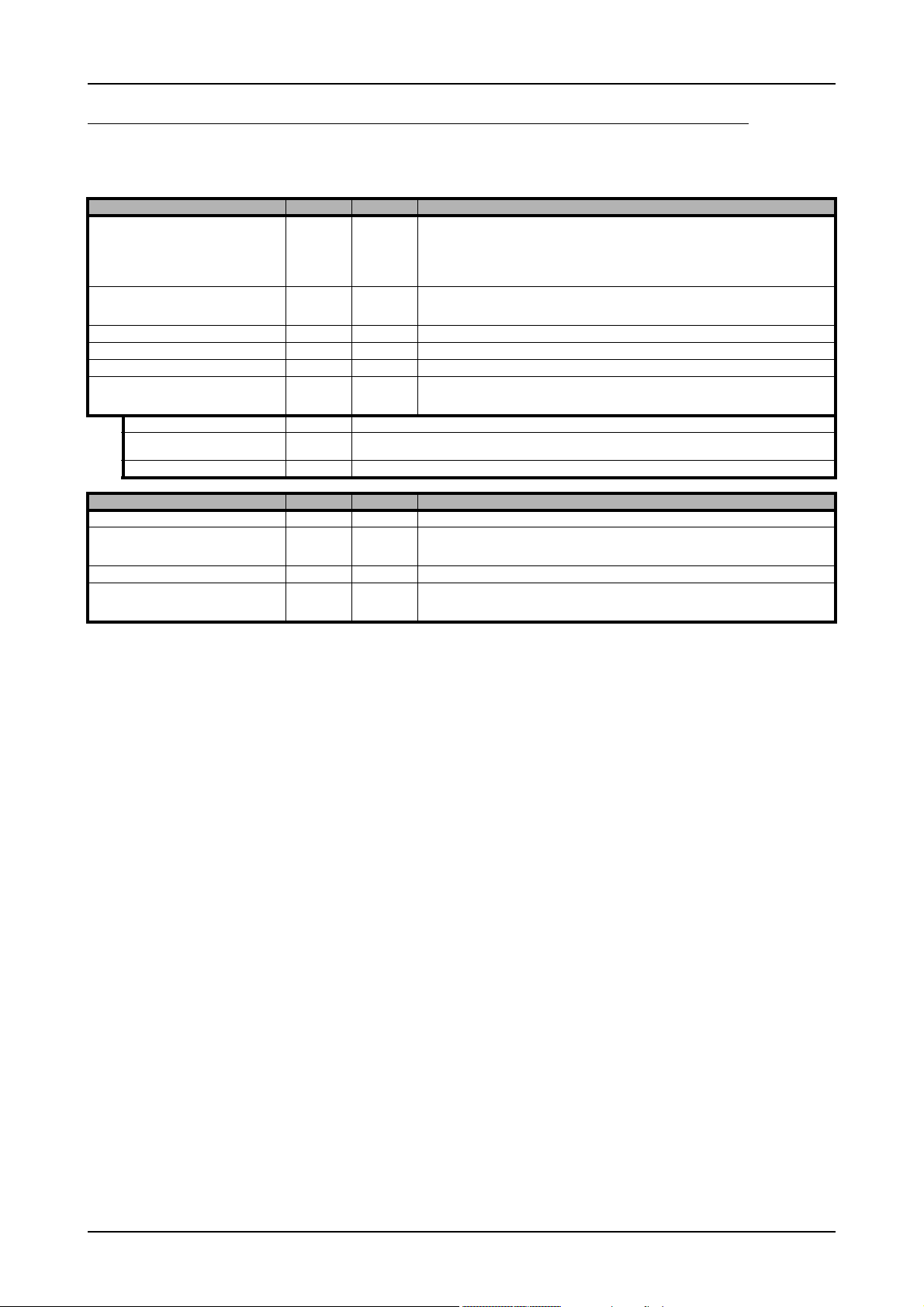
Gathering information from the digitizerNETBOX/generatorNETBOX
Gathering information from the digitizerNETBOX/generatorNETBOX
Information about the digitizerNETBOX/generatorNETBOX where the card is installed in can be read out through the card handle.
The following digitizerNETBOX/generatorNETBOX specifc information registers can be used:
Register Value Direction Description
SPC_NETBOX_TYPE 400000 read Hex coded version of the digitizerNETBOX/generatorNETBOX, example 02490110h:
SPC_NETBOX_SERIALNO 400001 read Serial number of the digitizerNETBOX/generatorNETBOX itself. In most cases the serial numbers of
SPC_NETBOX_PRODUCTIONDATE 400002 read Production date: week in bit 31 to 16, year in bit 15 to 0
SPC_NETBOX_HWVERSION 400003 read The hardware version of the digitizerNETBOX/generatorNETBOX products
SPC_NETBOX_SWVERSION 400004 read The software version of the installed remote server
SPC_NETBOX_FEATURES 400005 read Features of the digitizerNETBOX/generatorNETBOX. Holds the installed features and options as a
NETBOX_FEAT_DCPOWER 1h Is set if one of the DC power options are installed in the system.
NETBOX_FEAT_BOOTATPOWERON 2h Is set if the special feature automatic boot on power on is installed. This would allow remote devices to automatically
NETBOX_FEAT_EMBEDDEDSERVER 4h Is set if the option Embedded Server is installed.
Register Value Direction Description
SPC_NETBOX_CUSTOM 400006 read Custom code for custom modifications of the digitizerNETBOX/generatorNETBOX.
SPC_NETBOX_WAKEONLAN 400007 write This command is issed to wake a digitizerNETBOX/generatorNETBOX that is currently in standby-
SPC_NETBOX_MACADDRESS 400008 read Reads out the MAC address of the digitizerNETBOX/generatorNETBOX.
SPC_NETBOX_LANIDFLASH 400009 write By writing 1 to this register, one can start the autoamtic flashing of the LAN Id to detect a particulat
reboot after a failure of the power supply.
bit 24 to 31: Series: example 02h = DN2
bit 16 to 23: Family: example 49h = 49
bit 8 to 15: Speed grade: example 01h = 1
bit 0 to 7: Channels: example 10h = 16
Decoded example: DN2.491-16
the digitizerNETBOX/generatorNETBOX and the embedded cards are consecutive but there is no
guarantee for this.
bitfield. The read value must be masked out with one of the masks below to get information about
one certain feature.
mode with a special wake-on-lan message. Please note that the card handle is NULL in this case as
there is no opened card here. The argument is the MAC address of that device
digitizerNETBOX/generatorNETBOX that is installed in a Rack of multiple digitizerNETBOX or
generatorNETBOX devices. Writing a 0 to this register will stop the flashing again.
(c) Spectrum GmbH 77
Page 78

Channel Selection Analog Inputs
Analog Inputs
Channel Selection
One key setting that influences all other possible settings is the channel enable register. A unique feature of the Spectrum cards is the possibility
to program the number of channels you want to use. All on-board memory can then be used by these activated channels.
This description shows you the channel enable register for the complete card family. However, your specific board may have less channels
depending on the card type that you have purchased and therefore does not allow you to set the maximum number of channels shown here.
Register Value Direction Description
SPC_CHENABLE 11000 read/write Sets the channel enable information for the next card run.
CHANNEL0 1 Activates channel 0
CHANNEL1 2 Activates channel 1
CHANNEL2 4 Activates channel 2
CHANNEL3 8 Activates channel 3
The channel enable register is set as a bitmap. That means that one bit of the value corresponds to one channel to be activated. To activate
more than one channel the values have to be combined by a bitwise OR.
Example showing how to activate 4 channels:
spcm_dwSetParam_i32 (hDrv, SPC_CHENABLE, CHANNEL0 | CHANNEL1 | CHANNEL2 | CHANNEL3);
The following table shows all allowed settings for the channel enable register when your card has a maximum of 1 channel.
Channels to activate
Ch0 Values to program Value as hex Value as decimal
X CHANNEL0 1h 1
The following table shows all allowed settings for the channel enable register when your card has a maximum of 2 channels.
Channels to activate
Ch0 Ch1 Values to program Value as hex Value as decimal
X CHANNEL0 1h 1
X X CHANNEL0 | CHANNEL1 3h 3
X CHANNEL1 2h 2
The following table shows all allowed settings for the channel enable register in case that you have a four channel card.
Channels to activate
Ch0 Ch1 Ch2 Ch3 Values to program Value as hex Value as decimal
X CHANNEL0 1h 1
X CHANNEL1 2h 2
X CHANNEL2 4h 4
X X CHANNEL0 | CHANNEL1 3h 3
X X CHANNEL0 | CHANNEL2 5h 5
X X CHANNEL0 | CHANNEL3 9h 9
X X CHANNEL1 | CHANNEL2 6h 6
X X CHANNEL1 | CHANNEL3 Ah 10
X X X X CHANNEL0 | CHANNEL1 | CHANNEL2 | CHANNEL3 Fh 15
X CHANNEL3 8h 8
X X CHANNEL2 | CHANNEL3 Ch 12
Any channel activation mask that is not shown here is not valid. If programming an other channel activation,
the driver will return with an error code ERR_VALUE.
To help user programs it is also possible to read out the number of activated channels that correspond to the currently programmed bitmap.
Register Value Direction Description
SPC_CHCOUNT 11001 read Reads back the number of currently activated channels.
Reading out the channel enable information can be done directly after setting it or later like this:
spcm_dwSetParam_i32 (hDrv, SPC_CHENABLE, CHANNEL0 | CHANNEL1);
spcm_dwGetParam_i32 (hDrv, SPC_CHENABLE, &lActivatedChannels);
spcm_dwGetParam_i32 (hDrv, SPC_CHCOUNT, &lChCount);
printf ("Activated channels bitmask is: 0x%08x\n", lActivatedChannels);
printf ("Number of activated channels with this bitmask: %d\n", lChCount);
78 digitizerNETBOX DN2.44x Manual / DN6.44x Manual
Page 79

Analog Inputs Setting up the inputs
Assuming that the two channels are available on your card the program will have the following output:
Activated channels bitmask is: 0x00000003
Number of activated channels with this bitmask: 2
Important note on channels selection
As some of the manuals passages are used in more than one hardware manual most of the registers and
channel settings throughout this handbook are described for the maximum number of possible channels that
are available on one card of the current series. There can be less channels on your actual type of board or
bus-system. Please refer to the table(s) above to get the actual number of available channels.
Setting up the inputs
This analog acquisition board uses separate input stages and converters on each
channel. This gives you the possibility to set up the desired and concerning your
application best suiting input range also separately for each channel. All input
stage related settings can easily be set by the corresponding input registers. The
table below shows the available input stage registers and possible standard values
for your type of board. As there are also modified versions available with different
input ranges it is recommended to read out the currently available input ranges as
shown later in this chapter.
Input Path
Each input stage consists of different input paths each with different available settings and features. Please refer to the technical data section to get details on the
differences of the input paths.
Offering different input paths gives the choice to adopt the cards input stage to
the specific application in the best technical way by either using a high frequency
50 ohm path to have full bandwidth and best dynamic performance or by using
a buffered path with all features but limited bandwidth and dynamic performance.
All following settings are related to the selected input path. To read available features like input ranges or termination settings it is first necessary to set the input path for which the features are to be read.
Register Value Direction Description
SPC_READAIPATHCOUNT 3120 read Returns the number of available analog input paths
SPC_READAIPATH 3121 read/write Selects the input path which is used to read out the features. Please note that this settings does not
The following registers show the available input path settings
Register Value Direction Description
SPC_PATH0 30090 read/write Selects the analog input path for channel 0 (default path is path 0)
SPC_PATH1 30190 read/write Selects the analog input path for channel 1 (default path is path 0)
SPC_PATH2 30290 read/write Selects the analog input path for channel 2 (default path is path 0)
SPC_PATH3 30390 read/write Selects the analog input path for channel 3 (default path is path 0)
0 Input Path 0: Buffered inputs
1 Input Path 1: HF input with fixed 50 ohm termination
change the current path selection.
Input ranges
This analog acquisition board has several different input ranges for each channel.
This gives you the possibility to set up the desired and concerning your application
best suiting input range also separately for each channel. The input ranges can
easily be set by the corresponding input registers. The table below shows the available input registers and possible standard ranges for your type of board. As there
are also modified versions available with different input ranges it is recommended
to read out the currently available input ranges as shown later in this chapter.
(c) Spectrum GmbH 79
Page 80

Setting up the inputs Analog Inputs
Please note that the available ranges need to be read out separately for each input path. Please set the register SPC_READAIPATH as shown
above to select the input path for which the settings should be read. The available Input rages are read out using the following registers.
Register Value Direction Description
SPC_READAIPATH 3121 read/write Selects the input path which is used to read out the features.
SPC_READIRCOUNT 3000 read Returns the number of available input ranges for the input path selected by SPC_READAIPATH
SPC_READRANGEMIN0 4000 read Reads the lower border of input range 0 in mV
SPC_READRANGEMIN1 4001 read Reads the lower border of input range 1 in mV
... ... ...
SPC_READRANGEMAX0 4100 read Reads the upper border of input range 0 in mV
SPC_READRANGEMAX1 4101 read Reads the upper border of input range 1 in mV
... ... ...
The following example reads out the number of available input ranges and reads and prints the minimum and maximum value of all input
ranges.
spcm_dwGetParan_i32 (hDrv, SPC_READAIPATHCOUNT, &lNumOfPaths);
for (lPath = 0; lPath < lNumOfPaths; lPath++)
{
spcm_dwSetParan_i32 (hDrv, SPC_READAIPATH, lPath)
spcm_dwGetParam_i32 (hDrv, SPC_READIRCOUNT, &lNumberOfRanges);
for (i = 0; i < lNumberOfRanges; i++)
{
spcm_dwGetParam_i32 (hDrv, SPC_READRANGEMIN0 + i, &lMinimumInputRage);
spcm_dwGetParam_i32 (hDrv, SPC_READRANGEMAX0 + i, &lMaximumInputRange);
printf („Path %d Range %d: %d mV to %d mV\n“, lPath, i, lMinimumInputRange, lMaximumInputRange);
}
}
The input range is selected individually for each channel. Please note that the correct input path needs to be set
Register Value Direction Description
SPC_AMP0 30010 read/write Defines the input range of channel0.
SPC_AMP1 30110 read/write Defines the input range of channel1.
SPC_AMP2 30210 read/write Defines the input range of channel2.
SPC_AMP3 30310 read/write Defines the input range of channel3.
Standard Input ranges of path 0 (Buffered):
200 ± 200 mV calibrated input range for the appropriate channel.
500 ± 500 mV calibrated input range for the appropriate channel.
1000 ± 1 V calibrated input range for the appropriate channel.
2000 ± 2 V calibrated input range for the appropriate channel.
5000 ± 5 V calibrated input range for the appropriate channel.
10000 ± 10 V calibrated input range for the appropriate channel.
Standard Input ranges of path 1 (HF, 50 ohm terminated):
500 ± 500 mV calibrated input range for the appropriate channel.
1000 ± 1 V calibrated input range for the appropriate channel.
2500 ± 2.5 V calibrated input range for the appropriate channel.
5000 ± 5 V calibrated input range for the appropriate channel.
80 digitizerNETBOX DN2.44x Manual / DN6.44x Manual
Page 81

Analog Inputs Setting up the inputs
Input offset
In most cases the external signals will not be symmetrically related to ground. If you want to acquire such asymmetrical signals, it is possible to use the smallest input range that matches
the biggest absolute signal amplitude without exceeding the
range.
The figure at the right shows this possibility. But in this example you would leave half of the possible resolution unused.
It is much more efficient if you shift the signal on-board to be
as symmetrical as possible and to acquire it within the best
possible range.
This results in a much better use of the converters resolution.
On this acquisition boards from Spectrum you have the possibility to adjust the input offset separately for each channel.
The example in the right figure shows signals with a
range of ±1.0 V that have offsets up to ±1.0 V. So related to the desired input range these signals have offsets
of ±100 %.
For compensating such offsets you can use the offset register for each channel separately. If you want to compensate the +100 % offset of the outer left signal, you would
have to set the offset to -100 % to compensate it.
As the offset levels are relatively to the related input
range, you have to calculate and set your offset again
when changing the input’s range.
The table below shows the offset registers and the possible offset ranges for your specific type of board.
The input offset capability has been later added with a certain hardware version of the front-end module. To
check for availability on a specific card, simply read out the SPC_READAIFEATURES register and check whether
SPCM_AI_OFFSPERCENT flag has been set or not.
Register Value Direction Description Offset range
SPC_OFFS0 30000 read/write Defines the input’s offset and therefore shifts the input of channel0. Offset in percent of the input
SPC_OFFS1 30100 read/write Defines the input’s offset and therefore shifts the input of channel1.
SPC_OFFS2 30200 read/write Defines the input’s offset and therefore shifts the input of channel2.
SPC_OFFS3 30300 read/write Defines the input’s offset and therefore shifts the input of channel3.
range. Differs for different
ranges and input paths.
Please see table below for
allowed offsets.
Offset of path 0 (Buffered, DC-coupled):
Allowed input offset using path0 ± 200 mV input range –100 % .. 0% in steps of 1 %
Allowed input offset using path0 ± 500 mV input range –100 % .. 0% in steps of 1 %
Allowed input offset using path0 ± 1 V input range no Offset available
Allowed input offset using path0 ± 2 V input range –100 % .. 0% in steps of 1 %
Allowed input offset using path0 ± 5 V input range –100 % .. 0% in steps of 1 %
Allowed input offset using path0 ± 10 V input range no Offset available
Offset of path 1 (HF, 50 ohm terminated, DC-coupled):
Allowed input offset using path1 ± 500 mV input range –100 % .. 0% in steps of 1 %
Allowed input offset using path1 ± 1 V input range –100 % .. 0% in steps of 1 %
Allowed input offset using path1 ± 2.5 V input range –100 % .. 0% in steps of 1 %
Allowed input offset using path1 ± 5 V input range –100 % .. 0% in steps of 1 %
(c) Spectrum GmbH 81
Page 82

Setting up the inputs Analog Inputs
Read out of input features
Each input path (if multiple paths are available on the card) has different features that can be read out to make the software more general.
If you only operate one single card type in your software it is not necessary to read out these features.
Please note that the input features are read out for the currently selected read AI path done by register SPC_READAIPATH. Please also note
that the following table shows all input features settings that are available throughout all Spectrum acquisition cards. Some of these features
are not installed on your specific hardware. The column(s) for the input paths show which settings are available for which input path (if multiple
paths are available on the card) on a standard card:
Register Value Direction Description
SPC_READAIPATH 3121 read/write Selects the input path which is used to read out the features. Please note that this settings does not
SPC_READAIFEATURES 3101 read Returns a bit map with the available features of that input path. The possible return values are listed
Value Path 0 Path 1 Description
SPCM_AI_TERM 00000001h x fixed Programmable input termination available
SPCM_AI_SE 00000002h fixed fixed Input is single-ended. If available together with SPC_AI_DIFF: input type is software selectable
SPCM_AI_DIFF 00000004h Input is differential. If available together with SPC_AI_SE: input type is software selectable
SPCM_AI_OFFSPERCENT 00000008h x x Input offset programmable in per cent of input range
SPCM_AI_OFFSMV 00000010h Input offset programmable in mV
SPCM_AI_OVERRANGEDETECT 00000020h Programmable overrange detection available
SPCM_AI_DCCOUPLING 00000040h x x Input is DC coupled. If available together with AC coupling: coupling is software selectable
SPCM_AI_ACCOUPLING 00000080h x x Input is AC coupled. If available together with DC coupling: coupling is software selectable
SPCM_AI_LOWPASS 00000100h x x Input has a selectable low pass filter (bandwidth limit)
SPCM_AI_ACDC_OFFS_COMP 00000200h x Input has a selectable offset compensation for HF-Path with AC/DC coupling/source mismatch.
SPCM_AI_AUTOCALOFFS 00001000h x x Input offset can be auto calibrated on the card
SPCM_AI_AUTOCALGAIN 00002000h x Input gain can be auto calibrated on the card
SPCM_AI_AUTOCALOFFSNOIN 00004000h Input offset can auto calibrated on the card if inputs are left open
SPCM_AI_HIGHIMP 00008000h x Input has a high impedance mode available
SPCM_AI_LOWIMP 00010000h x x Input has a low impedance mode (50 Ohm) available
change the current path selection.
below.
The following example shows a setup of path and input range of a two channel card.
Please note that this is a general example and the number of input channels may not match your card channels.
spcm_dwSetParam_i32 (hDrv, SPC_PATH0 , 0); // Set up channel0 to input path 0 (buffered)
spcm_dwSetParam_i32 (hDrv, SPC_AMP0 , 1000); // Set up channel0 to the range of ± 1.0 V
spcm_dwSetParam_i32 (hDrv, SPC_PATH1 , 1); // Set up channel1 to input path 1 (HF, 50 ohm terminated)
spcm_dwSetParam_i32 (hDrv, SPC_AMP1 , 500); // Set up channel1 to the range of ± 0.5 V
Input termination
The Spectrum analog acquisition cards of the M4i series offer an input path with
fixed 50 ohm termination (HF path, 50 ohm path) as well as a second input path
with all features to be programmed by the user (buffered path). If the HF path with
fixed 50 ohm termination is activated this register will have no functionality.
The buffered input path can be terminated separately with 50 Ohm by software
programming. If you do so, please make sure that your signal source is able to
deliver the higher output currents. If no termination is used, the inputs have an impedance of 1 Megaohm. The following table shows the corresponding register to
set the input termination.
Register Value Direction Description
SPC_50OHM0 30030 read/write A „1“ sets the 50 ohm termination for channel0. A „0“ sets the termination to1 MOhm.
SPC_50OHM1 30130 read/write A „1“ sets the 50 ohm termination for channel1. A „0“ sets the termination to1 MOhm.
SPC_50OHM2 30230 read/write A „1“ sets the 50 ohm termination for channel2. A „0“ sets the termination to1 MOhm.
SPC_50OHM3 30330 read/write A „1“ sets the 50 ohm termination for channel3. A „0“ sets the termination to1 MOhm.
82 digitizerNETBOX DN2.44x Manual / DN6.44x Manual
Page 83

Analog Inputs Setting up the inputs
Input coupling
All inputs can be set separately switched to AC or DC coupling. Please refer to
the technical data section to see the signal frequency range that is available for
the different settings.
Using the AC coupling will eliminate all DC and low frequency parts of the input
signal and allows best quality measurements in the frequency domain even if the
DC level of the signal varies over the time.
The following table shows the corresponding register to set the input coupling.
Register Value Direction Description
SPC_ACDC0 30020 read/write A „1“ sets the AC coupling for channel0. A „0“ sets the DC coupling (default is DC)
SPC_ACDC1 30120 read/write A „1“ sets the AC coupling for channel1. A „0“ sets the DC coupling (default is DC)
SPC_ACDC2 30220 read/write A „1“ sets the AC coupling for channel2. A „0“ sets the DC coupling (default is DC)
SPC_ACDC3 30320 read/write A „1“ sets the AC coupling for channel3. A „0“ sets the DC coupling (default is DC)
AC/DC offset compensation
When using the HF-Path of the input channel, an offset voltage will be visible in case DC coupling is selected for the channel and the signal
source is externally AC coupled. This offset can be compensated for by setting the compensation registers:
Register Value Direction Description
SPC_ACDC_OFFS_COMPENSATION0 30021 read/write A „1“ enables the compensation. A „0“ disables the compensation (default).
SPC_ACDC_OFFS_COMPENSATION1 30121 read/write A „1“ enables the compensation. A „0“ disables the compensation (default).
SPC_ACDC_OFFS_COMPENSATION2 30221 read/write A „1“ enables the compensation. A „0“ disables the compensation (default).
SPC_ACDC_OFFS_COMPENSATION3 30321 read/write A „1“ enables the compensation. A „0“ disables the compensation (default).
Anti aliasing filter (Bandwidth limit)
All inputs have a separate selectable anti aliasing filter (bandwidth limit) that will
cut off any aliasing effects and that will reduce signal noise.
Please note that this bandwidth limit filter will also cut of any distortion or high
frequency spurious signals parts that are within the frequency spectrum of the
input.
Please refer to the technical data section to see the cut off frequency and the type
of filter used. The following table shows the corresponding register to activate
the bandwidth limit.
Register Value Direction Description
SPC_FILTER0 30080 read/write A „1“ selects the bandwidth limit for channel 0. A „0“ set the channel to full bandwidth (default is full)
SPC_FILTER1 30180 read/write A „1“ selects the bandwidth limit for channel 1. A „0“ set the channel to full bandwidth (default is full
SPC_FILTER2 30280 read/write A „1“ selects the bandwidth limit for channel 2. A „0“ set the channel to full bandwidth (default is full
SPC_FILTER3 30380 read/write A „1“ selects the bandwidth limit for channel 3. A „0“ set the channel to full bandwidth (default is full
Automatic on-board calibration of the offset and gain settings
All of the channels are calibrated in factory before the board is shipped. These values are stored in the on-board EEProm under the default
settings. If you have asymmetrical signals, you can adjust the offset easily with the corresponding registers of the inputs as shown before.
To start the automatic offset adjustment, simply write the register, mentioned in the following table.
Before you start an automatic offset adjustment make sure, that no signal is connected to any input. Leave
all the input connectors open and then start the adjustment. All the internal settings of the driver are changed,
while the automatic offset compensation is in progress.
Register Value Direction Description
SPC_ADJ_AUTOADJ 50020 write Performs the automatic offset compensation in the driver either for all input ranges or only the actual.
ADJ_ALL 0 Automatic offset adjustment for all input ranges.
As all settings are temporarily stored in the driver, the automatic adjustment will only affect these values. After exiting your program, all calibration information will be lost. To give you a possibility to save your own settings, most Spectrum card have at least one set of user settings
(c) Spectrum GmbH 83
Page 84

Setting up the inputs Analog Inputs
that can be saved within the on-board EEPROM. The default settings of the offset and gain values are then read-only and cannot be written
to the EEPROM by the user. If the card has no user settings the default settings may be overwritten.
You can easily either save adjustment settings to the EEPROM with SPC_ADJ_SAVE or recall them with SPC_ADJ_LOAD. These two registers
are shown in the table below. The values for these EEPROM access registers are the sets that can be stored within the EEPROM. The amount
of sets available for storing user offset settings depends on the type of board you use. The table below shows all the EEPROM sets, that are
available for your board.
Register Value Direction Description
SPC_ADJ_LOAD 50000 write Loads the specified set of settings from the EEPROM. The default settings are automatically loaded,
read Reads out, what kind of settings have been loaded last.
SPC_ADJ_SAVE 50010 write Stores the current settings to the specified set in the EEPROM.
read Reads out, what kind of settings have been saved last.
ADJ_DEFAULT 0 Default settings, no user settings available
If you want to make an offset and gain adjustment on all the channels and store the data to the ADJ_DEFAULT set of the EEPROM you can
when the driver is started.
do this the way, the following example shows.
spcm_dwSetParam_i32 (hDrv, SPC_ADJ_AUTOADJ, ADJ_ALL ); // Activate offset/gain adjustment on all channels
spcm_dwSetParam_i32 (hDrv, SPC_ADJ_SAVE , ADJ_DEFAULT); // and store values to DEFAULT set in the EEPROM
84 digitizerNETBOX DN2.44x Manual / DN6.44x Manual
Page 85

Acquisition modes Overview
Acquisition modes
Your card is able to run in different modes. Depending on the selected mode there are different registers that each define an aspect of this
mode. The single modes are explained in this chapter. Any further modes that are only available if an option is installed on the card is documented in a later chapter.
Overview
This chapter gives you a general overview on the related registers for the different modes. The use of these registers throughout the different
modes is described in the following chapters.
Setup of the mode
The mode register is organized as a bitmap. Each mode corresponds to one bit of this bitmap. When defining the mode to use, please be
sure just to set one of the bits. All other settings will return an error code.
The main difference between all standard and all FIFO modes is that the standard modes are limited to on-board memory and therefore can
run with full sampling rate. The FIFO modes are designed to transfer data continuously over the bus to PC memory or to hard disk and can
therefore run much longer. The FIFO modes are limited by the maximum bus transfer speed the PC can use. The FIFO mode uses the complete
installed on-board memory as a FIFO buffer.
However as you’ll see throughout the detailed documentation of the modes the standard and the FIFO mode are similar in programming and
behavior and there are only a very few differences between them.
Register Value Direction Description
SPC_CARDMODE 9500 read/write Defines the used operating mode, a read command will return the currently used mode.
SPC_AVAILCARDMODES 9501 read Returns a bitmap with all available modes on your card. The modes are listed below.
Acquisition modes
Mode Value Available on Description
SPC_REC_STD_SINGLE 1h all cards Data acquisition to on-board memory for one single trigger event.
SPC_REC_STD_MULTI 2h all cards Data acquisition to on-board memory for multiple trigger events. Each recorded segment has the same size.
SPC_REC_STD_GATE 4h all cards Data acquisition to on-board memory using an external Gate signal. Acquisition is only done as long as the
SPC_REC_STD_ABA 8h digitizer only Data acquisition to on-board memory for multiple trigger events. While the multiple trigger events are stored
SPC_REC_STD_SEGSTATS 10000h M4i/M4x.22xx
SPC_REC_STD_AVERAGE 20000h M4i/M4x.22xx
SPC_REC_STD_BOXCAR 800000h M4i/M4x.44xx
SPC_REC_FIFO_SINGLE 10h all cards Continuous data acquisition for one single trigger event. The on-board memory is used completely as FIFO
SPC_REC_FIFO_MULTI 20h all cards Continuous data acquisition for multiple trigger events.
SPC_REC_FIFO_GATE 40h all cards Continuous data acquisition using an external gate signal.
SPC_REC_FIFO_ABA 80h digitizer only Continuous data acquisition for multiple trigger events together with continuous data acquisition with a
SPC_REC_FIFO_SEGSTATS 100000h M4i/M4x.22xx
SPC_REC_FIFO_AVERAGE 200000h M4i/M4x.22xx
SPC_REC_FIFO_BOXCAR 1000000h M4i/M4x.44xx
SPC_REC_FIFO_SINGLE_MONITOR 2000000h digitizer only Combination of SPC_REC_FIFO_SINGLE mode with additional slower sampling clock data stream for moni-
M4i/M4x.44xx
DN2/DN6.22x
DN2/DN6.44x
digitizer only
M4i/M4x.44xx
DN2/DN6.22x
DN2/DN6.44x
digitizer only
DN2/DN6.44x
digitizer only
M4i/M4x.44xx
DN2/DN6.22x
DN2/DN6.44x
digitizer only
M4i/M4x.44xx
DN2/DN6.22x
DN2/DN6.44x
digitizer only
DN2/DN6.44x
digitizer only
This mode is described in greater detail in a special chapter about the Multiple Recording option.
gate signal has a programmed level. The mode is described in greater detail in a special chapter about the
Gated Sampling option.
with programmed sampling rate the inputs are sampled continuously with a slower sampling speed. The
mode is described in a special chapter about ABA mode option.
Data acquisition to on-board memory for multiple trigger events, using Block/Segment Statistic Module
(FPGA firmware Option).
Data acquisition to on-board memory for multiple trigger events, using Block Average Module (FPGA firmware Option).
Enables Boxcar Averaging for standard acquisition. Requires digitizer module with firmware version V29 or
newer.
buffer.
slower sampling clock.
Enables Block/Segment Statistic for FIFO acquisition (FPGA firmware Option).
Enables Block Averaging for FIFO acquisition (FPGA firmware Option).
Enables Boxcar Averaging for FIFO acquisition. Requires digitizer module firmware version V29 or newer.
toring purposes (same as A-data of SPC_REC_FIFO_ABA mode).
(c) Spectrum GmbH 85
Page 86

Commands Acquisition modes
Commands
The data acquisition/data replay is controlled by the command register. The command register controls the state of the card in general and
also the state of the different data transfers. Data transfers are explained in an extra chapter later on.
The commands are split up into two types of commands: execution commands that fulfill a job and wait commands that will wait for the
occurrence of an interrupt. Again the commands register is organized as a bitmap allowing you to set several commands together with one
call. As not all of the command combinations make sense (like the combination of reset and start at the same time) the driver will check the
given command and return an error code ERR_SEQUENCE if one of the given commands is not allowed in the current state.
Register Value Direction Description
SPC_M2CMD 100 write only Executes a command for the card or data transfer.
Card execution commands
M2CMD_CARD_RESET 1h Performs a hard and software reset of the card as explained further above.
M2CMD_CARD_WRITESETUP 2h Writes the current setup to the card without starting the hardware. This command may be useful if changing some
M2CMD_CARD_START 4h Starts the card with all selected settings. This command automatically writes all settings to the card if any of the set-
M2CMD_CARD_ENABLETRIGGER 8h The trigger detection is enabled. This command can be either sent together with the start command to enable trigger
M2CMD_CARD_FORCETRIGGER 10h This command forces a trigger even if none has been detected so far. Sending this command together with the start
M2CMD_CARD_DISABLETRIGGER 20h The trigger detection is disabled. All further trigger events are ignored until the trigger detection is again enabled.
M2CMD_CARD_STOP 40h Stops the current run of the card. If the card is not running this command has no effect.
internal settings like clock frequency and enabling outputs.
tings has been changed since the last one was written. After card has been started none of the settings can be
changed while the card is running.
immediately or in a second call after some external hardware has been started.
command is similar to using the software trigger.
When starting the card the trigger detection is started disabled.
Card wait commands
These commands do not return until either the defined state has been reached which is signaled by an interrupt from the card or the timeout
counter has expired. If the state has been reached the command returns with an ERR_OK. If a timeout occurs the command returns with
ERR_TIMEOUT. If the card has been stopped from a second thread with a stop or reset command, the wait function returns with ERR_ABORT.
M2CMD_CARD_WAITPREFULL 1000h Acquisition modes only: the command waits until the pretrigger area has once been filled with data. After pretrigger
M2CMD_CARD_WAITTRIGGER 2000h Waits until the first trigger event has been detected by the card. If using a mode with multiple trigger events like Multi-
M2CMD_CARD_WAITREADY 4000h Waits until the card has completed the current run. In an acquisition mode receiving this command means that all data
area has been filled the internal trigger engine starts to look for trigger events if the trigger detection has been
enabled.
ple Recording or Gated Sampling there only the first trigger detection will generate an interrupt for this wait command.
has been acquired. In a generation mode receiving this command means that the output has stopped.
Wait command timeout
If the state for which one of the wait commands is waiting isn’t reached any of the wait commands will either wait forever if no timeout is
defined or it will return automatically with an ERR_TIMEOUT if the specified timeout has expired.
Register Value Direction Description
SPC_TIMEOUT 295130 read/write Defines the timeout for any following wait command in a millisecond resolution. Writing a zero to this
register disables the timeout.
As a default the timeout is disabled. After defining a timeout this is valid for all following wait commands until the timeout is disabled again
by writing a zero to this register.
A timeout occurring should not be considered as an error. It did not change anything on the board status. The board is still running and will
complete normally. You may use the timeout to abort the run after a certain time if no trigger has occurred. In that case a stop command is
necessary after receiving the timeout. It is also possible to use the timeout to update the user interface frequently and simply call the wait
function afterwards again.
Example for card control:
// card is started and trigger detection is enabled immediately
spcm_dwSetParam_i32 (hDrv, SPC_M2CMD, M2CMD_CARD_START | M2CMD_CARD_ENABLETRIGGER);
// we wait a maximum of 1 second for a trigger detection. In case of timeout we force the trigger
spcm_dwSetParam_i32 (hDrv, SPC_TIMEOUT, 1000);
if (spcm_dwSetParam_i32 (hDrv, SPC_M2CMD, M2CMD_CARD_WAITTRIGGER) == ERR_TIMEOUT)
{
printf (“No trigger detected so far, we force a trigger now!\n”);
spcm_dwSetParam (hdrv, SPC_M2CMD, M2CMD_CARD_FORCETRIGGER);
}
// we disable the timeout and wait for the end of the run
spcm_dwSetParam_i32 (hDrv, SPC_TIMEOUT, 0);
spcm_dwSetParam_i32 (hDrv, SPC_M2CMD, M2CMD_CARD_WAITREADY);
printf (“Card has stopped now!\n”);
86 digitizerNETBOX DN2.44x Manual / DN6.44x Manual
Page 87

Acquisition modes Commands
Card Status
In addition to the wait for an interrupt mechanism or completely instead of it one may also read out the current card status by reading the
SPC_M2STATUS register. The status register is organized as a bitmap showing the status of the card and also of the different data transfers.
Register Value Direction Description
SPC_M2STATUS 110 read only Reads out the current status information
M2STAT_CARD_PRETRIGGER 1h Acquisition modes only: the pretrigger area has been filled.
M2STAT_CARD_TRIGGER 2h The first trigger has been detected.
M2STAT_CARD_READY 4h The card has finished its run and is ready.
M2STAT_CARD_SEGMENT_PRETRG 8h Multi/ABA/Gated acquisition of M4i/M4x/M2p only: the pretrigger area of one segment has been filled.
Acquisition cards status overview
The following drawing gives you an overview of the card commands and card status information. After start of card with
M2CMD_CARD_START the card is acquiring pretrigger data until one time complete pretrigger data has been acquired. Then the status
M2STAT_CARD_PRETRIGGER is set. Either the trigger has been enabled together with the start command or the card now waits for trigger
enable command M2CMD_CARD_ENABLETRIGGER. After receiving this command the trigger engine is enabled and card checks for a trigger event. As soon as the trigger event is received the status changes to M2STAT_CARD_TRIGGER and the card acquires the programmed
posttrigger data. After all post trigger data has been acquired the status changes to M2STAT_CARD_READY and data can be read out:
Generation card status overview
This drawing gives an overview of the card commands and status information for a simple generation mode. After start of card with the
M2CMD_CARD_START the card is armed and waiting. Either the trigger has been enabled together with the start command or the card now
waits for trigger enable command M2CMD_CARD_ENABLETRIGGER. After receiving this command the trigger engine is enabled and card
checks for a trigger event. As soon as the trigger event is received the status changes to M2STAT_CARD_TRIGGER and the card starts with
the data replay. After replay has been finished - depending on the programmed mode - the status changes to M2STAT_CARD_READY and
the card stops.
Data Transfer
Data transfer consists of two parts: the buffer definition and the commands/status information that controls the transfer itself. Data transfer
shares the command and status register with the card control commands and status information. In general the following details on the data
transfer are valid for any data transfer in any direction:
• The memory size register (SPC_MEMSIZE) must be programmed before starting the data transfer.
• Before starting a data transfer the buffer must be defined using the spcm_dwDefTransfer function.
• Each defined buffer is only used once. After transfer has ended the buffer is automatically invalidated.
• If a buffer has to be deleted although the data transfer is in progress or the buffer has at least been defined it is necessary to call the
spcm_dwInvalidateBuf function.
(c) Spectrum GmbH 87
Page 88

Commands Acquisition modes
Definition of the transfer buffer
Before any data transfer can start it is necessary to define the transfer buffer with all its details. The definition of the buffer is done with the
spcm_dwDefTransfer function as explained in an earlier chapter.
uint32 _stdcall spcm_dwDefTransfer_i64 (// Defines the transfer buffer by using 64 bit unsigned integer values
drv_handle hDevice, // handle to an already opened device
uint32 dwBufType, // type of the buffer to define as listed below under SPCM_BUF_XXXX
uint32 dwDirection, // the transfer direction as defined below
uint32 dwNotifySize, // number of bytes after which an event is sent (0=end of transfer)
void* pvDataBuffer, // pointer to the data buffer
uint64 qwBrdOffs, // offset for transfer in board memory
uint64 qwTransferLen); // buffer length
This function is used to define buffers for standard sample data transfer as well as for extra data transfer for additional ABA or timestamp
information. Therefore the dwBufType
SPCM_BUF_DATA 1000 Buffer is used for transfer of standard sample data
SPCM_BUF_ABA 2000 Buffer is used to read out slow ABA data. Details on this mode are described in the chapter about the ABA mode
SPCM_BUF_TIMESTAMP 3000 Buffer is used to read out timestamp information. Details on this mode are described in the chapter about the
parameter can be one of the following:
option
timestamp option.
The dwDirection
parameter defines the direction of the following data transfer:
SPCM_DIR_PCTOCARD 0 Transfer is done from PC memory to on-board memory of card
SPCM_DIR_CARDTOPC 1 Transfer is done from card on-board memory to PC memory.
SPCM_DIR_CARDTOGPU 2 RDMA transfer from card memory to GPU memory, SCAPP option needed, Linux only
SPCM_DIR_GPUTOCARD 3 RDMA transfer from GPU memory to card memory, SCAPP option needed, Linux only
The direction information used here must match the currently used mode. While an acquisition mode is used
there’s no transfer from PC to card allowed and vice versa. It is possible to use a special memory test mode
to come beyond this limit. Set the SPC_MEMTEST register as defined further below.
The dwNotifySize
parameter defines the amount of bytes after which an interrupt should be generated. If leaving this parameter zero, the
transfer will run until all data is transferred and then generate an interrupt. Filling in notify size > zero will allow you to use the amount of
data that has been transferred so far. The notify size is used on FIFO mode to implement a buffer handshake with the driver or when transferring large amount of data where it may be of interest to start data processing while data transfer is still running. Please see the chapter on
handling positions further below for details.
The Notify size sticks to the page size which is defined by the PC hardware and the operating system. Therefore the notify size must be a multiple of 4 kByte. For data transfer it may also be a fraction of 4k in the
range of 16, 32, 64, 128, 256, 512, 1k or 2k. No other values are allowed. For ABA and timestamp the notify
size can be 2k as a minimum. If you need to work with ABA or timestamp data in smaller chunks please use the
polling mode as described later.
The pvDataBuffer
must point to an allocated data buffer for the transfer. Please be sure to have at least the amount of memory allocated that
you program to be transferred. If the transfer is going from card to PC this data is overwritten with the current content of the card on-board
memory.
When not doing FIFO mode one can also use the qwBrdOffs
parameter. This parameter defines the starting position for the data transfer as
byte value in relation to the beginning of the card memory. Using this parameter allows it to split up data transfer in smaller chunks if one
has acquired a very large on-board memory.
The qwTransferLen
parameter defines the number of bytes that has to be transferred with this buffer. Please be sure that the allocated memory
has at least the size that is defined in this parameter. In standard mode this parameter cannot be larger than the amount of data defined with
memory size.
Memory test mode
In some cases it might be of interest to transfer data in the opposite direction. Therefore a special memory test mode is available which allows
random read and write access of the complete on-board memory. While memory test mode is activated no normal card commands are processed:
Register Value Direction Description
SPC_MEMTEST 200700 read/write Writing a 1 activates the memory test mode, no commands are then processed.
88 digitizerNETBOX DN2.44x Manual / DN6.44x Manual
Writing a 0 deactivates the memory test mode again.
Page 89

Acquisition modes Commands
Invalidation of the transfer buffer
The command can be used to invalidate an already defined buffer if the buffer is about to be deleted by user. This function is automatically
called if a new buffer is defined or if the transfer of a buffer has completed
uint32 _stdcall spcm_dwInvalidateBuf ( // invalidate the transfer buffer
drv_handle hDevice, // handle to an already opened device
uint32 dwBufType); // type of the buffer to invalidate as listed above under SPCM_BUF_XXXX
The dwBufType
parameter need to be the same parameter for which the buffer has been defined:
SPCM_BUF_DATA 1000 Buffer is used for transfer of standard sample data
SPCM_BUF_ABA 2000 Buffer is used to read out slow ABA data. Details on this mode are described in the chapter about the ABA mode
SPCM_BUF_TIMESTAMP 3000 Buffer is used to read out timestamp information. Details on this mode are described in the chapter about the times-
option. The ABA mode is only available on analog acquisition cards.
tamp option. The timestamp mode is only available on analog or digital acquisition cards.
Commands and Status information for data transfer buffers.
As explained above the data transfer is performed with the same command and status registers like the card control. It is possible to send
commands for card control and data transfer at the same time as shown in the examples further below.
Register Value Direction Description
SPC_M2CMD 100 write only Executes a command for the card or data transfer
M2CMD_DATA_STARTDMA 10000h Starts the DMA transfer for an already defined buffer. In acquisition mode it may be that the card hasn’t received a
M2CMD_DATA_WAITDMA 20000h Waits until the data transfer has ended or until at least the amount of bytes defined by notify size are available. This
M2CMD_DATA_STOPDMA 40000h Stops a running DMA transfer. Data is invalid afterwards.
trigger yet, in that case the transfer start is delayed until the card receives the trigger event
wait function also takes the timeout parameter described above into account.
The data transfer can generate one of the following status information:
Register Value Direction Description
SPC_M2STATUS 110 read only Reads out the current status information
M2STAT_DATA_BLOCKREADY 100h The next data block as defined in the notify size is available. It is at least the amount of data available but it also can
M2STAT_DATA_END 200h The data transfer has completed. This status information will only occur if the notify size is set to zero.
M2STAT_DATA_OVERRUN 400h The data transfer had on overrun (acquisition) or underrun (replay) while doing FIFO transfer.
M2STAT_DATA_ERROR 800h An internal error occurred while doing data transfer.
be more data.
Example of data transfer
void* pvData = (void*) new int8[1024];
// transfer data from PC memory to card memory (on replay cards) ...
spcm_dwDefTransfer_i64 (hDrv, SPCM_BUF_DATA, SPCM_DIR_PCTOCARD , 0, pvData, 0, 1024);
spcm_dwSetParam_i32 (hDrv, SPC_M2CMD, M2CMD_DATA_STARTDMA | M2CMD_DATA_WAITDMA);
// ... or transfer data from card memory to PC memory (acquisition cards)
spcm_dwDefTransfer_i64 (hDrv, SPCM_BUF_DATA, SPCM_DIR_CARDTOPC , 0, pvData, 0, 1024);
spcm_dwSetParam_i32 (hDrv, SPC_M2CMD, M2CMD_DATA_STARTDMA | M2CMD_DATA_WAITDMA);
// explicitely stop DMA tranfer prior to invalidating buffer
spcm_dwSetParam_i32 (hDrv, SPC_M2CMD, M2CMD_DATA_STOPDMA);
spcm_dwInvalidateBuf (hDrv, SPCM_BUF_DATA);
delete [] (int8*) pvData;
To keep the example simple it does no error checking. Please be sure to check for errors if using these command in real world programs!
Users should take care to explicitly send the M2CMD_DATA_STOPDMA command prior to invalidating the
buffer, to avoid crashes due to race conditions when using higher-latency data transportation layers, such
as to remote Ethernet devices.
(c) Spectrum GmbH 89
Page 90

Standard Single acquisition mode Acquisition modes
Standard Single acquisition mode
The standard single mode is the easiest and mostly used mode to acquire analog data with a Spectrum acquisition card. In standard single
recording mode the card is working totally independent from the PC, after the card setup is done. The advantage of the Spectrum boards is
that regardless to the system usage the card will sample with equidistant time intervals.
The sampled and converted data is stored in the on-board memory and is held there for being read out after the acquisition. This mode allows
sampling at very high conversion rates without the need to transfer the data into the memory of the host system at high speed.
After the recording is done, the data can be read out by the user and is transferred via the bus into PC memory.
This standard recording mode is the most common mode for all analog and digital acquisition and oscilloscope boards. The data is
written to a programmed amount of the on-board memory (memsize). That part of memory is used as a ring buffer, and recording
is done continuously until a trigger event is detected. After the trigger event, a certain programmable amount of data is recorded
(post trigger) and then the recording finishes. Due to the continuous
ring buffer recording, there are also samples prior to the trigger
event in the memory (pretrigger).
When the card is started the pre trigger area is filled up with data first. While doing this the board’s trigger
detection is not armed. If you use a huge pre trigger size and a slow sample rate it can take some time after
starting the board before a trigger event will be detected.
Card mode
The card mode has to be set to the correct mode SPC_REC_STD_SINGLE.
Register Value Direction Description
SPC_CARDMODE 9500 read/write Defines the used operating mode, a read command will return the currently used mode.
SPC_REC_STD_SINGLE 1h Data acquisition to on-board memory for one single trigger event.
Memory, Pre- and Posttrigger
At first you have to define, how many samples are to be recorded at all and how many of them should be acquired after the trigger event
has been detected.
Register Value Direction Description
SPC_MEMSIZE 10000 read/write Sets the memory size in samples per channel.
SPC_POSTTRIGGER 10100 read/write Sets the number of samples to be recorded per channel after the trigger event has been detected.
You can access these settings by the register SPC_MEMSIZE, which sets the total amount of data that is recorded, and the register
SPC_POSTTRIGGER, that defines the number of samples to be recorded after the trigger event has been detected. The size of the pretrigger
results on the simple formula:
pretrigger = memsize - posttrigger
The maximum memsize that can be use for recording is of course limited by the installed amount of memory and by the number of channels
to be recorded. Please have a look at the topic "Limits of pre, post memsize, loops" later in this chapter.
Example
The following example shows a simple standard single mode data acquisition setup with the read out of data afterwards. To keep this example
simple there is no error checking implemented.
int32 lMemsize = 16384; // recording length is set to 16 kSamples
spcm_dwSetParam_i32 (hDrv, SPC_CHENABLE, CHANNEL0); // only one channel activated
spcm_dwSetParam_i32 (hDrv, SPC_CARDMODE, SPC_REC_STD_SINGLE); // set the standard single recording mode
spcm_dwSetParam_i32 (hDrv, SPC_MEMSIZE, lMemsize); // recording length
spcm_dwSetParam_i32 (hDrv, SPC_POSTTRIGGER, 8192); // samples to acquire after trigger = 8k
// now we start the acquisition and wait for the interrupt that signalizes the end
spcm_dwSetParam_i32 (hDrv, SPC_M2CMD, M2CMD_CARD_START | M2CMD_CARD_ENABLETRIGGER | M2CMD_CARD_WAITREADY);
void* pvData = new int16[lMemsize];
// read out the data
spcm_dwDefTransfer_i64 (hDrv, SPCM_BUF_DATA, SPCM_DIR_CARDTOPC , 0, pvData, 0, 2 * lMemsize);
spcm_dwSetParam_i32 (hDrv, SPC_M2CMD, M2CMD_DATA_STARTDMA | M2CMD_DATA_WAITDMA);
90 digitizerNETBOX DN2.44x Manual / DN6.44x Manual
Page 91

Acquisition modes FIFO Single acquisition mode
FIFO Single acquisition mode
The FIFO single mode does a continuous data acquisition using the on-board memory as a FIFO buffer and transferring data continuously to
PC memory. One can make on-line calculations with the acquired data, store the data continuously to disk for later use or even have a data
logger functionality with on-line data display.
Card mode
The card mode has to be set to the correct mode SPC_REC_FIFO_SINGLE.
Register Value Direction Description
SPC_CARDMODE 9500 read/write Defines the used operating mode, a read command will return the currently used mode.
SPC_REC_FIFO_SINGLE 10h Continuous data acquisition to PC memory. Complete on-board memory is used as FIFO buffer.
Length and Pretrigger
Even in FIFO mode it is possible to program a pretrigger area. In general FIFO mode can run forever until it is stopped by an explicit user
command or one can program the total length of the transfer by two counters Loop and Segment size
Register Value Direction Description
SPC_PRETRIGGER 10030 read/write Programs the number of samples to be acquired before the trigger event detection
SPC_SEGMENTSIZE 10010 read/write Length of segments to acquire.
SPC_LOOPS 10020 read/write Number of segments to acquire in total. If set to zero the FIFO mode will run continuously until it is
stopped by the user.
The total amount of samples per channel that is acquired can be calculated by [SPC_LOOPS * SPC_SEGMENTSIZE]. Please stick to the below
mentioned limitations of the registers.
Difference to standard single acquisition mode
The standard modes and the FIFO modes differ not very much from the programming side. In fact one can even use the FIFO mode to get the
same behavior like the standard mode. The buffer handling that is shown in the next chapter is the same for both modes.
Pretrigger
When doing standard single acquisition memory is used as a circular buffer and the pre trigger can be up to the [installed memory] - [minimum
post trigger]. Compared to this the pre trigger in FIFO mode is limited by a special pre trigger FIFO and hence considerably shorter.
Length of acquisition.
In standard mode the acquisition length is defined before the start and is limited to the installed on-board memory whilst in FIFO mode the
acquisition length can either be defined or it can run continuously until user stops it.
Example FIFO acquisition
The following example shows a simple FIFO single mode data acquisition setup with the read out of data afterwards. To keep this example
simple there is no error checking implemented.
spcm_dwSetParam_i32 (hDrv, SPC_CHENABLE, CHANNEL0); // only one channel activated
spcm_dwSetParam_i32 (hDrv, SPC_CARDMODE, SPC_REC_FIFO_SINGLE); // set the FIFO single recording mode
spcm_dwSetParam_i32 (hDrv, SPC_PRETRIGGER, 1024); // 1 kSample of data before trigger
// in FIFO mode we need to define the buffer before starting the transfer
int16* pnData = new int16[lBufsizeInSamples];
spcm_dwDefTransfer_i64 (hDrv, SPCM_BUF_DATA, SPCM_DIR_CARDTOPC, 4096, (void*) pnData, 0, 2 * lBufsizeInSamples);
// now we start the acquisition and wait for the first block
dwError = spcm_dwSetParam_i32 (hDrv, SPC_M2CMD, M2CMD_CARD_START | M2CMD_CARD_ENABLETRIGGER);
dwError = spcm_dwSetParam_i32 (hDrv, SPC_M2CMD, M2CMD_DATA_STARTDMA | M2CMD_DATA_WAITDMA);
// we acquire data in a loop. As we defined a notify size of 4k we’ll get the data in >=4k chuncks
llTotalBytes = 0;
while (!dwError)
{
// read out the available bytes
spcm_dwGetParam_i64 (hDrv, SPC_DATA_AVAIL_USER_LEN, &llAvailBytes);
llTotalBytes += llAvailBytes;
// here is the right position to do something with the data (printf is limited to 32 bit variables)
printf ("Currently Available: %d, total: %d\n", (int32) llAvailBytes, (int32) llTotalBytes);
// now we free the number of bytes and wait for the next buffer
spcm_dwSetParam_i64 (hDrv, SPC_DATA_AVAIL_CARD_LEN, llAvailBytes);
dwError = spcm_dwSetParam_i32 (hDrv, SPC_M2CMD, M2CMD_DATA_WAITDMA);
}
(c) Spectrum GmbH 91
Page 92

Limits of pre trigger, post trigger, memory size Acquisition modes
Limits of pre trigger, post trigger, memory size
The maximum memory size parameter is only limited by the number of activated channels and by the amount of installed memory. Please
keep in mind that each sample needs 2 bytes of memory to be stored. Minimum memory size as well as minimum and maximum post trigger
limits are independent of the activated channels or the installed memory.
Due to the internal organization of the card memory there is a certain stepsize when setting these values that has to be taken into account.
The following table gives you an overview of all limits concerning pre trigger, post trigger, memory size, segment size and loops. The table
shows all values in relation to the installed memory size in samples. If more memory is installed the maximum memory size figures will increase
according to the complete installed memory
Activated Used Memory size Pre trigger Post trigger Segment size Loops
Channels Mode SPC_MEMSIZE SPC_PRETRIGGER SPC_POSTTRIGGER SPC_SEGMENTSIZE SPC_LOOPS
1 Ch Standard Single 32 Mem 16 16 Mem - 16 16 16 8G - 16 16 not used not used
Standard Multi/ABA 32 Mem 16 16 8k 16 16 Mem/2-16 16 32 Mem/2 16 not used
Standard Gate 32 Mem 16 16 8k 16 16 Mem-16 16 not used not used
Standard Average For the limits in this mode please refer to the dedicated chapter in this manual.
FIFO Single not used 16 8k 16 not used 32 8G - 16 16 0 (∞)4G - 1 1
FIFO Multi/ABA not used 16 8k 16 16 8G - 16 16 32 pre+post 16 0 (∞)4G - 1 1
FIFO Gate not used 16 8k 16 16 8G - 16 16 not used 0 (∞)4G - 1 1
FIFO Average For the limits in this mode please refer to the dedicated chapter in this manual.
2 Ch Standard Single 32 Mem/2 16 16 Mem/2 - 16 16 16 8G - 16 16 not used not used
Standard Multi/ABA 32 Mem/2 16 16 8k 16 16 Mem/4-16 16 32 Mem/4 16 not used
Standard Gate 32 Mem/2 16 16 8k 16 16 Mem/2-16 16 not used not used
Standard Average For the limits in this mode please refer to the dedicated chapter in this manual.
FIFO Single not used 16 8k 16 not used 32 8G - 16 16 0 (∞)4G - 1 1
FIFO Multi/ABA not used 16 8k 16 16 8G - 16 16 32 pre+post 16 0 (∞)4G - 1 1
FIFO Gate not used 16 8k 16 16 8G - 16 16 not used 0 (∞)4G - 1 1
FIFO Average For the limits in this mode please refer to the dedicated chapter in this manual.
4 Ch Standard Single 32 Mem/4 16 16 Mem/4 - 16 16 16 8G - 16 16 not used not used
Standard Multi/ABA 32 Mem/4 16 16 8k 16 16 Mem/8-16 16 32 Mem/8 16 not used
Standard Gate 32 Mem/4 16 16 8k 16 16 Mem/4-16 16 not used not used
Standard Average For the limits in this mode please refer to the dedicated chapter in this manual.
FIFO Single not used 16 8k 16 not used 32 8G - 16 16 0 (∞)4G - 1 1
FIFO Multi/ABA not used 16 8k 16 16 8G - 16 16 32 pre+post 16 0 (∞)4G - 1 1
FIFO Gate not used 16 8k 16 16 8G - 16 16 not used 0 (∞)4G - 1 1
FIFO Average For the limits in this mode please refer to the dedicated chapter in this manual.
Min Max Step Min Max Step Min Max Step Min Max Step Min Max Step
(defined by mem and post)
(defined by segment and post)
(defined by segment and post)
(defined by mem and post)
(defined by segment and post)
(defined by segment and post)
(defined by mem and post)
(defined by segment and post)
(defined by segment and post)
All figures listed here are given in samples. An entry of [8G - 16] means [8 GSamples - 16] = 8,589,934,576 samples.
The given memory and memory / divider figures depend on the installed on-board memory as listed below:
Installed Memory
Mem 2 GSample
Mem / 2 1 GSample
Mem / 4 512 MSample
Mem / 8 256 MSample
2 GSample
Please keep in mind that this table shows all values at once. Only the absolute maximum and minimum values are shown. There might be
additional limitations. Which of these values is programmed depends on the used mode. Please read the detailed documentation of the mode.
92 digitizerNETBOX DN2.44x Manual / DN6.44x Manual
Page 93

Acquisition modes Buffer handling
Buffer handling
To handle the huge amount of data that can possibly be acquired with the M4i/M4x/M2p series cards, there is a very reliable two step
buffer strategy set up. The on-board memory of the card can be completely used as a real FIFO buffer. In addition a part of the PC memory
can be used as an additional software buffer. Transfer between hardware FIFO and software buffer is performed interrupt driven and automatically by the driver to get best performance. The following drawing will give you an overview of the structure of the data transfer handling:
Although an M4i is shown here, this applies to M4x and M2p cards as well. A data buffer handshake is implemented in the driver which
allows to run the card in different data transfer modes. The software transfer buffer is handled as one large buffer which is on the one side
controlled by the driver and filled automatically by busmaster DMA from/to the hardware FIFO buffer and on the other hand it is handled by
the user who set’s parts of this software buffer available for the driver for further transfer. The handshake is fulfilled with the following 3 software registers:
Register Value Direction Description
SPC_DATA_AVAIL_USER_LEN 200 read Returns the number of currently to the user available bytes inside a sample data transfer.
SPC_DATA_AVAIL_USER_POS 201 read Returns the position as byte index where the currently available data samples start.
SPC_DATA_AVAIL_CARD_LEN 202 write Writes the number of bytes that the card can now use for sample data transfer again
Internally the card handles two counters, a user counter and a card counter. Depending on the transfer direction the software registers have
slightly different meanings:
Transfer direction Register Direction Description
Write to card SPC_DATA_AVAIL_USER_LEN read This register contains the currently available number of bytes that are free to write new data to the
SPC_DATA_AVAIL_CARD_LEN write After filling an amount of the buffer with new data to transfer to card, the user tells the driver with this
Read from card SPC_DATA_AVAIL_USER_LEN read This register contains the currently available number of bytes that are filled with newly transferred
SPC_DATA_AVAIL_CARD_LEN write After finishing the job with the new available data the user needs to tell the driver that this amount of
Any direction SPC_DATA_AVAIL_USER_POS read The register holds the current byte index position where the available bytes start. The register is just
Any direction SPC_FILLSIZEPROMILLE read The register holds the current fill size of the on-board memory (FIFO buffer) in promille (1/1000) of
card. The user can now fill this amount of bytes with new data to be transferred.
register that the amount of data is now ready to transfer.
data. The user can now use this data for own purposes, copy it, write it to disk or start calculations
with this data.
bytes is again free for new data to be transferred.
intended to help you and to avoid own position calculation
the full on-board memory. Please note that the hardware reports the fill size only in 1/16 parts of the
full memory. The reported fill size is therefore only shown in 1000/16 = 63 promille steps.
Directly after start of transfer the SPC_DATA_AVAIL_USER_LEN is every time zero as no data is available for the user and the
SPC_DATA_AVAIL_CARD_LEN is every time identical to the length of the defined buffer as the complete buffer is available for the card for
transfer.
The counter that is holding the user buffer available bytes (SPC_DATA_AVAIL_USER_LEN) is relates to the notify
size at the DefTransfer call. Even when less bytes already have been transferred you won’t get notice of it in
case the notify size is programmed to a higher value.
Remarks
• The transfer between hardware FIFO buffer and application buffer is done with scatter-gather DMA using a busmaster DMA controller
located on the card. Even if the PC is busy with other jobs data is still transferred until the application data buffer is completely used.
• Even if application data buffer is completely used there’s still the hardware FIFO buffer that can hold data until the complete on-board
memory is used. Therefore a larger on-board memory will make the transfer more reliable against any PC dead times.
• As you see in the above picture data is directly transferred between application data buffer and on-board memory. Therefore it is abso-
lutely critical to delete the application data buffer without stopping any DMA transfers that are running actually. It is also absolutely criti-
(c) Spectrum GmbH 93
Page 94

Buffer handling Acquisition modes
cal to define the application data buffer with an unmatching length as DMA can than try to access memory outside the application data
area.
• As shown in the drawing above the DMA control will announce new data to the application by sending an event. Waiting for an event is
done internally inside the driver if the application calls one of the wait functions. Waiting for an event does not consume any CPU time
and is therefore highly desirable if other threads do a lot of calculation work. However it is not necessary to use the wait functions and
one can simply request the current status whenever the program has time to do so. When using this polling mode the announced available bytes still stick to the defined notify size!
• If the on-board FIFO buffer has an overrun (card to PC) or an underrun (PC to card) data transfer is stopped. However in case of transfer
from card to PC there is still a lot of data in the on-board memory. Therefore the data transfer will continue until all data has been transferred although the status information already shows an overrun.
• Getting best bus transfer performance is done using a „continuous buffer“. This mode is explained in the appendix in greater detail.
The Notify size sticks to the page size which is defined by the PC hardware and the operating system. Therefore the notify size must be a multiple of 4 kByte. For data transfer it may also be a fraction of 4k in the
range of 16, 32, 64, 128, 256, 512, 1k or 2k. No other values are allowed. For ABA and timestamp the notify
size can be 2k as a minimum. If you need to work with ABA or timestamp data in smaller chunks please use the
polling mode as described later.
The following graphs will show the current buffer positions in different states of the transfer. The drawings have been made for the transfer
from card to PC. However all the block handling is similar for the opposite direction, just the empty and the filled parts of the buffer are
inverted.
Step 1: Buffer definition
Directly after buffer definition the complete buffer is empty (card to PC) or
completely filled (PC to card). In our example we have a notify size which
is 1/4 of complete buffer memory to keep the example simple. In real
world use it is recommended to set the notify size to a smaller stepsize.
Step 2: Start and first data available
In between we have started the transfer and have waited for the first data
to be available for the user. When there is at least one block of notify size
in the memory we get an interrupt and can proceed with the data. Any
data that already was transferred is announced. The USER_POS is still
zero as we are right at the beginning of the complete transfer.
Step 3: set the first data available for card
Now the data can be processed. If transfer is going from card to PC that
may be storing to hard disk or calculation of any figures. If transfer is going from PC to card that means we have to fill the available buffer again
with data. After the amount of data that has been processed by the user
application we set it available for the card and for the next step.
Step 4: next data available
After reaching the next border of the notify size we get the next part of the
data buffer to be available. In our example at the time when reading the
USER_LEN even some more data is already available. The user position
will now be at the position of the previous set CARD_LEN.
Step 5: set data available again
Again after processing the data we set it free for the card use.
In our example we now make something else and don’t react to the interrupt for a longer time. In the background the buffer is filled with more data.
Step 6: roll over the end of buffer
Now nearly the complete buffer is filled. Please keep in mind that our current user position is still at the end of the data part that we processed and
marked in step 4 and step 5. Therefore the data to process now is split in
two parts. Part 1 is at the end of the buffer while part 2 is starting with
address 0.
Step 7: set the rest of the buffer available
Feel free to process the complete data or just the part 1 until the end of
the buffer as we do in this example. If you decide to process complete
buffer please keep in mind the roll over at the end of the buffer.
This buffer handling can now continue endless as long as we manage to
set the data available for the card fast enough. The USER_POS and USER_LEN for step 8 would now look exactly as the buffer shown in step 2.
94 digitizerNETBOX DN2.44x Manual / DN6.44x Manual
Page 95

Acquisition modes Buffer handling
Buffer handling example for transfer from card to PC
char* pcData = new char[lBufferSizeInBytes];
// we now define the transfer buffer with the minimum notify size of on page = 4 kByte
spcm_dwDefTransfer_i64 (hDrv, SPCM_BUF_DATA, SPCM_DIR_CARDTOPC , 4096, (void*) pcData, 0, lBufferSizeInBytes);
// we start the DMA transfer
dwError = spcm_dwSetParam_i32 (hDrv, SPC_M2CMD, M2CMD_DATA_STARTDMA);
do
{
if (!dwError)
{
// we wait for the next data to be available. Afte this call we get at least 4k of data to proceed
dwError = spcm_dwSetParam_i32 (hDrv, SPC_M2CMD, M2CMD_DATA_WAITDMA);
// if there was no error we can proceed and read out the available bytes that are free again
spcm_dwGetParam_i32 (hDrv, SPC_DATA_AVAIL_USER_LEN, &lAvailBytes);
spcm_dwGetParam_i32 (hDrv, SPC_DATA_AVAIL_USER_POS, &lBytePos);
printf (“We now have %d new bytes available\n”, lAvailBytes);
printf (“The available data starts at position %d\n”, lBytesPos);
// we take care not to go across the end of the buffer
if ((lBytePos + lAvailBytes) >= lBufferSizeInBytes)
lAvailBytes = lBufferSizeInBytes - lBytePos;
// our do function gets a pointer to the start of the available data section and the length
vDoSomething (&pcData[lBytesPos], lAvailBytes);
// the buffer section is now immediately set available for the card
spcm_dwSetParam_i32 (hDrv, SPC_DATA_AVAIL_CARD_LEN, lAvailBytes);
}
}
while (!dwError); // we loop forever if no error occurs
Buffer handling example for transfer from PC to card
char* pcData = new char[lBufferSizeInBytes];
// before starting transfer we ned to once fill complete buffer memory with data
vDoGenerateData (&pcData[0], lBufferSizeInBytes);
// we now define the transfer buffer with the minimum notify size of on page = 4 kByte
spcm_dwDefTransfer_i64 (hDrv, SPCM_BUF_DATA, SPCM_DIR_PCTOCARD , 4096, (void*) pcData, 0, lBufferSizeInBytes);
// before start we once have to fill some data in for the start of the output
spcm_dwSetParam_i32 (hDrv, SPC_DATA_AVAIL_CARD_LEN, lBufferSizeInBytes);
dwError = spcm_dwSetParam_i32 (hDrv, SPC_M2CMD, M2CMD_DATA_STARTDMA | M2CMD_DATA_WAITDMA);
do
{
if (!dwError)
{
// if there was no error we can proceed and read out the current amount of available data
spcm_dwGetParam_i32 (hDrv, SPC_DATA_AVAIL_USER_LEN, &lAvailBytes);
spcm_dwGetParam_i32 (hDrv, SPC_DATA_AVAIL_USER_POS, &lBytePos);
printf (“We now have %d free bytes available\n”, lAvailBytes);
printf (“The available data starts at position %d\n”, lBytesPos);
// we take care not to go across the end of the buffer
if ((lBytePos + lAvailBytes) >= lBufferSizeInBytes)
lAvailBytes = lBufferSizeInBytes - lBytePos;
// our do function gets a pointer to the start of the available data section and the length
vDoGenerateData (&pcData[lBytesPos], lAvailBytes);
// now we mark the number of bytes that we just generated for replay
// and wait for the next free buffer
spcm_dwSetParam_i32 (hDrv, SPC_DATA_AVAIL_CARD_LEN, lAvailBytes);
dwError = spcm_dwSetParam_i32 (hDrv, SPC_M2CMD, M2CMD_DATA_WAITDMA);
}
}
while (!dwError); // we loop forever if no error occurs
Please keep in mind that you are using a continuous buffer writing/reading that will start again at the zero
position if the buffer length is reached. However the DATA_AVAIL_USER_LEN register will give you the complete amount of available bytes even if one part of the free area is at the end of the buffer and the second
half at the beginning of the buffer.
(c) Spectrum GmbH 95
Page 96

Data organization Acquisition modes
Data organization
Data is organized in a multiplexed way in the transfer buffer. If using 2 channels data of first activated channel comes first, then data of
second channel.
Activated Channels Ch0 Ch1 Ch2 Ch3 Samples ordering in buffer memory starting with data offset zero
1 channel X A0 A1 A2 A3 A4 A5 A6 A7 A8 A9 A10 A11 A12 A13 A14 A15 A16
1 channel X B0 B1 B2 B3 B4 B5 B6 B7 B8 B9 B10 B11 B12 B13 B14 B15 B16
1 channel X C0 C1 C2 C3 C4 C5 C6 C7 C8 C9 C10 C11 C12 C13 C14 C15 C16
1 channel X D0 D1 D2 D3 D4 D5 D6 D7 D8 D9 D10 D11 D12 D13 D14 D15 D16
2 channels X X A0 B0 A1 B1 A2 B2 A3 B3 A4 B4 A5 B5 A6 B6 A7 B7 A8
2 channels X X A0C0A1C1A2C2A3C3A4C4A5C5A6C6A7C7A8
2 channels X X A0 D0 A1 D1 A2 D2 A3 D3 A4 D4 A5 D5 A6 D6 A7 D7 A8
2 channels X X B0 C0 B1 C1 B2 C2 B3 C3 B4 C4 B5 C5 B6 C6 B7 C7 B8
2 channels X X B0 D0 B1 D1 B2 D2 B3 D3 B4 D4 B5 D5 B6 D6 B7 D7 B8
2 channels X X C0 D0 C1 D1 C2 D2 C3 D3 C4 D4 C5 D5 C6 D6 C7 D7 C8
4 channels X X X X A0 B0 C0 D0 A1 B1 C1 D1 A2 B2 C2 D2 A3 B3 C3 D3 A4
The samples are re-named for better readability. A0 is sample 0 of channel 0, B4 is sample 4 of channel 1, and so on.
Sample format
If the card is using 14 bit A/D samples, they are stored in two’s complement in the lower 14 bit of the 16 bit data word. 14 bit resolution
means that data is ranging from -8192…to…+8191. In standard mode the upper two bits contain the sign extension allowing to directly use
the read data as 16 bit integer values. If the card is using 16 bit A/D samples, they are stored in two’s complement in the 16 bit data word.
16 bit resolution means that data is ranging from -32768…to…+32767:
Standard Mode Digital inputs enabled Digital inputs enabled
SPCM_XMODE_DIGIN SPCM_XMODE_DIGIN2BIT
M4i.445x,
M4i.448x
Data bit 14 bit
D15 ADx Bit 13
D14 ADx Bit 13
D13 ADx Bit 13 (MSB) ADx Bit 13 ADx Bit 13 (MSB) ADx Bit 14 ADx Bit 13 (MSB) ADx Bit 15 (MSB)
D12 ADx Bit 12 ADx Bit 12 ADx Bit 12 ADx Bit 13 ADx Bit 12 ADx Bit 14
D11 ADx Bit 11 ADx Bit 11 ADx Bit 11 ADx Bit 12 ADx Bit 11 ADx Bit 13
D10 ADx Bit 10 ADx Bit 10 ADx Bit 10 ADx Bit 11 ADx Bit 10 ADx Bit 12
D9 ADx Bit 9 ADx Bit 9 ADx Bit 9 ADx Bit 10 ADx Bit 9 ADx Bit 11
D8 ADx Bit 8 ADx Bit 8 ADx Bit 8 ADx Bit 9 ADx Bit 8 ADx Bit 10
D7 ADx Bit 7 ADx Bit 7 ADx Bit 7 ADx Bit 8 ADx Bit 7 ADx Bit 9
D6 ADx Bit 6 ADx Bit 6 ADx Bit 6 ADx Bit 7 ADx Bit 6 ADx Bit 8
D5 ADx Bit 5 ADx Bit 5 ADx Bit 5 ADx Bit 6 ADx Bit 5 ADx Bit 7
D4 ADx Bit 4 ADx Bit 4 ADx Bit 4 ADx Bit 5 ADx Bit 4 ADx Bit 6
D3 ADx Bit 3 ADx Bit 3 ADx Bit 3 ADx Bit 4 ADx Bit 3 ADx Bit 5
D2 ADx Bit 2 ADx Bit 2 ADx Bit 2 ADx Bit 3 ADx Bit 2 ADx Bit 4
D1 ADx Bit 1 ADx Bit 1 ADx Bit 1 ADx Bit 2 ADx Bit 1 ADx Bit 3
D0 ADx Bit 0 (LSB) ADx Bit 0 (LSB) ADx Bit 0 (LSB) ADx Bit 1 (LSB) ADx Bit 0 (LSB) ADx Bit 2 (LSB)
ADC resolution
(sign extension)
(sign extension)
M4i.441x,
M4i.442x,
M4i.447x
16 bit
ADC resolution
ADx Bit 15 (MSB) 44x1 (4 Ch) models:
ADx Bit 14 ADx Bit 13
M4i.445x,
M4i.448x
14 bit
ADC resolution
Ch3: Digital bit 0 (X0)
Ch2: Digital bit 2 (X2)
Ch1: Digital bit 1 (X1)
Ch0: Digital bit 0 (X0)
44x0 (2 Ch) models:
Ch1: Digital bit 1 (X2)
Ch0: Digital bit 0 (X0)
(sign extension)
M4i.441x,
M4i.442x,
M4i.447x
15 bit
ADC resolution
444x1 (4 Ch) models:
Ch3: Digital bit 0 (X0)
Ch2: Digital bit 2 (X2)
Ch1: Digital bit 1 (X1)
Ch0: Digital bit 0 (X0)
44x0 (2 Ch) models:
Ch1: Digital bit 1 (X2)
Ch0: Digital bit 0 (X0)
ADx Bit 15 (MSB) 44x1 (4 Ch) models:
M4i.445x,
M4i.448x
14 bit
ADC resolution
44x1 (4 Ch) models:
Ch3: Digital bit 0 (X0)
Ch2: Digital bit 2 (X2)
Ch1: Digital bit 1 (X1)
Ch0: Digital bit 0 (X0)
44x0 (2 Ch) models:
Ch1: Digital bit 1 (X2)
Ch0: Digital bit 0 (X0)
Ch3: Digital bit 1 (X1)
Ch2: Digital bit 0 (X0)
Ch1: Digital bit 2 (X2)
Ch0: Digital bit 1 (X1)
44x0 (2 Ch) models:
Ch1: Digital bit 1 (X0)
Ch0: Digital bit 0 (X1)
M4i.441x,
M4i.442x,
M4i.447x
14 bit
ADC resolution
44x1 (4 Ch) models:
Ch3: Digital bit 0 (X0)
Ch2: Digital bit 2 (X2)
Ch1: Digital bit 1 (X1)
Ch0: Digital bit 0 (X0)
44x0 (2 Ch) models:
Ch1: Digital bit 1 (X2)
Ch0: Digital bit 0 (X0)
44x1 (4 Ch) models:
Ch3: Digital bit 1 (X1)
Ch2: Digital bit 0 (X0)
Ch1: Digital bit 2 (X2)
Ch0: Digital bit 1 (X1)
44x0 (2 Ch) models:
Ch1: Digital bit 1 (X0)
Ch0: Digital bit 0 (X1)
96 digitizerNETBOX DN2.44x Manual / DN6.44x Manual
Page 97

Acquisition modes Sample format
Converting ADC samples to voltage values
The Spectrum driver also contains a register that holds the value of the decimal value of the full scale representation of the installed ADC. This
value should be used when converting ADC values (in LSB) into real-world voltage values, because this register also automatically takes any
specialities into account, such as slightly reduced ADC resolution with reserved codes for gain/offset compensation.
Register Value Direction Description
SPC_MIINST_MAXADCVALUE 1126 read Contains the decimal code (in LSB) of the ADC full scale value.
In case of a board that uses an 8 bit ADC that provides the full ADC code (without reserving any bits) the returned value would be 128. The the peak value for
a ±1.0 V input range would be 1.0 V (or 1000 mv).
A returned sample value of for example +49 (decimal, two’s complement,
signed representation) would then convert to:
A returned sample value of for example -55 (decimal) would then convert to:
Vin49
V
in
1000 mV
----------------------------------------------
× 382.81 mV==
128
1000 mV
----------------------------------------------
55–
× 429.69 mV–==
128
When converting samples that contain any additional data such as for example additional digital channels
or overrange bits, this extra information must be first masked out and a proper sign-extension must be performed, before these values can be used as a signed two’s complement value for above formulas.
Applying correction factors when using special clock mode
When using the card in the so called special clock mode (SPC_SPECIALCLOCK) the full-scale ADC input range changes with the selected
sample rate. This can be compensated for by additionally multiplying the above calculated voltage values with the proper correction factors.
The procedure on how to obtain these factors from the driver is described in the dedicated clock chapter later in this manual.
(c) Spectrum GmbH 97
Page 98

Overview Clock generation
Clock generation
Overview
The Spectrum M4i PCI Express (PCIe) and M4x PXI Express (PXIe) cards
offer a wide variety of different clock modes to match all the customers’
needs. All of the clock modes are described in detail with programming
examples in this chapter.
The figure is showing an overview of the complete engine used on all M4i
cards for clock generation.
The purpose of this chapter is to give you a guide to the best matching
clock settings for your specific application and needs.
Clock Mode Register
The selection of the different clock modes has to be done by the SPC_CLOCKMODE register. All available modes, can be read out by the
help of the SPC_AVAILCLOCKMODES register.
Register Value Direction Description
SPC_AVAILCLOCKMODES 20201 read Bitmask, in which all bits of the below mentioned clock modes are set, if available.
SPC_CLOCKMODE 20200 read/write Defines the used clock mode or reads out the actual selected one.
SPC_CM_INTPLL 1 Enables internal programmable high precision Quartz 1 for sample clock generation
SPC_CM_QUARTZ2 4 Enables optional Quartz 2 as reference for sample clock generation
SPC_CM_EXTREFCLOCK 32 Enables internal PLL with external reference for sample clock generation
SPC_CM_PXIREFCLOCK 64 M4x cards only: Enables internal PLL with PXIe backplane clock as reference for sample clock generation
The different clock modes and all other related or required register settings are described on the following pages.
The different clock modes
Standard internal sample rate (programmable reference quartz 1)
This is the easiest and most common way to generate a sample rate with no need for additional external clock signals. The sample rate has
a very fine resolution, low jitter and a high accuracy. The Quartz 1 is a high quality software programmable clock device acting as a reference to the internal PLL. The specification is found in the technical data section of this manual.
Quartz2 with PLL (option, M4i cards only)
This optional second Quartz 2 is for special customer needs, either for a special direct sampling clock or as a very precise reference for the
PLL. Please feel free to contact Spectrum for your special needs. The Quarz 2 clock footprint can be equipped with a wide variety of clock
sources that are available on the market.
External Clock (reference clock)
Any clock can be fed in that matches the specification of the board. The external clock signal can be used to synchronize the board on a
system clock or to feed in an exact matching sample rate. The external clock is divided/multiplied using a PLL allowing a wide range of
external clock modes.
PXIe Reference Clock (M4x cards only)
The PXIe reference clock is a 100 MHz high-quality differential clock signal with an accuracy of ±100 ppm or better. This reference clock is
located on the PXIe backplane and is routed to every PXIe slot with the same trace length on the mainboard’s PCB. PXIe cards from Spectrum
are able to use the PXIe reference clock for sampling clock generation. One big advantage of using the reference clock is the fact that all
cards that are synchronized to the reference clock are running with the same clock frequency.
Synchronization Clock (option Star-Hub, M4i cards only)
The star-hub option allows the synchronization of up to 8 cards of the M4i series from Spectrum with a minimal phase delay between the
different cards. The clock is distributed from the master card to all connected cards. As a source it is possible to either use the programmable
Quarz 1 clock or the external Ext0 reference clock input of the master card. For details on the synchronization option please take a look at
the dedicated chapter later in this manual.
98 digitizerNETBOX DN2.44x Manual / DN6.44x Manual
Page 99

Clock generation Details on the different clock modes
Details on the different clock modes
Standard internal sampling clock (PLL)
The internal sampling clock is generated in default mode by a programmable high precision quartz. You need to select the clock mode by
the dedicated register shown in the table below:
Register Value Direction Description
SPC_CLOCKMODE 20200 read/write Defines the used clock mode
SPC_CM_INTPLL 1 Enables internal programmable high precision Quartz 1 for sample clock generation
The user does not have to care about how the desired sampling rate is generated by multiplying and dividing internally. You simply write the
desired sample rate to the according register shown in the table below and the driver makes all the necessary calculations. If you want to
make sure the sample rate has been set correctly you can also read out the register and the driver will give you back the sampling rate that
is matching your desired one best.
Register Value Direction Description
SPC_SAMPLERATE 20000 write Defines the sample rate in Hz for internal sample rate generation.
read Read out the internal sample rate that is nearest matching to the desired one.
Independent of the used clock source it is possible to enable the clock output. The clock will be available on the external clock output connector
and can be used to synchronize external equipment with the board.
Register Value Direction Description
SPC_CLOCKOUT 20110 read/write Writing a „1“ enables clock output on external clock output connector. Writing a „0“ disables the
SPC_CLOCKOUTFREQUENCY 20111 read Allows to read out the frequency of an internally synthesized clock present at the clock output.
clock output (tristate)
Example on writing and reading internal sampling rate
spcm_dwSetParam_i32 (hDrv, SPC_CLOCKMODE, SPC_CM_INTPLL); // Enables internal programmable quartz 1
spcm_dwSetParam_i64 (hDrv, SPC_SAMPLERATE, 62500000); // Set internal sampling rate to 62.5 MHz
spcm_dwSetParam_i32 (hDrv, SPC_CLOCKOUT, 1); // enable the clock output of the card
spcm_dwGetParam_i64 (hDrv, SPC_SAMPLERATE, &lSamplerate); // Read back the programmed sample rate and print
printf („Sample rate = %d\n“, lSamplerate); // it. Output should be „Sample rate = 62500000“
In standard clock mode, which is the default setting, the sampling rate can only be programmed as maximum samplingrate and divisions of this. Valid sampling rates are [max], [max/2], [max/4], [max/8], ...
[max/131072]. Any programmed sampling rate in between will automatically be rounded to the next
matching divided sampling clock.
Minimum internal sampling rate
The minimum and the maximum internal sampling rates depend on the specific type of board. Both values can be found in the technical data
section of this manual.
Clock Setup Granularity and Divider (Special Clock Mode)
High performance ADC’s are very sensitive devices concerning clocking and have a relatively wide variation of its full-scale range versus the
used sample clock. The manual states "As the ADC is fed with nearly any sampling rate the gain accuracy is reduced and may be worse
than the specified one.
So the default is, that the ADC is always running with its maximum sample rate, in case of the M4i.442x cards with 250 MHz. That way,
this ADC specific variation is out of the way, and the card can be factory offset and gain calibrated.
When using "fine clock granularity" mode, the ADCs internal full-scale range changes ... and that way the input ranges change. So let's say
one selects the ±500 mV input range on an M4i.442x card then - ideally spoken - applying a DC value of +500 mV would lead to the ADC
full-scale code of +32767, because this card has a 16bit ADC.
That is valid for all sample rates that can be derived from the calibrated maximum sample rate of in this case of a M4i.442x card 250 MS/s.
So selecting divided sample rates like 125 MS/s (250/2), 62.5 MS/s (250/4), 31.125 MS/s (250/8) does not affect gain accuracy at all,
that is why this special clock mode is not the default. These dividers do not affect the real sample clock to the ADC chip, but simply drop
samples (what we refer to as oversampling), so that the ADC configuration and operation does not change here.
When providing a sample clock to the ADC chip other than the calibrated one, the full-scale range changes. So let's say you again selected
the ±500 mV input range, then applying the same DC value of +500 mV would not lead to the same ADC full-scale code of +32767 any
more, but instead in fact to a larger one, so that actually the „new“ input range is smaller than the specified one.
That is why this continuous clock mode is not the default, because the full scale range of the ADC itself unfortunately varies over clock frequency quite widely ...something in the range of 20..30 %.
(c) Spectrum GmbH 99
Page 100

Details on the different clock modes Clock generation
This behavior does not differ between internal sampling clock and external reference clock. In every case the sample clock that is applied to
the ADC chip is generated by a PLL from a known reference, either internally or externally fed into the card.
To offer best performance to each individual user there are two different modes of clock setup, each with its own advantages:
• Standard Clock Mode (default): the clock is internally programmed using the maximum sampling rate and a divider. In this mode the
specified gain accuracy is reached but the available sampling rates are limited. For a M4i.4450-x8 (2 channels 500 MS/s) this mode
would result into possible sampling rates of 500 MS/s, 250 MS/s, 125 MS/s, 62.5 MS/s, ... The driver automatically adjusts the sampling rate to the nearest matching one. If programming a sampling rate of 400 MS/s this will automatically be adjusted to 500 MS/s in
the case that the SPC_SPECIALCLOCK register is not set.
• Special Clock Mode (Fine Clock Granularity): this mode has to be activated by software before
setting the sampling rate. After activation
nearly every sampling rate can be programmed with a clock resolution of 1 Hz. However there are some gaps in the clock range which
are specified in the technical data section. Sampling rates within the specified gaps can not be used by this card.
As the ADC is fed with nearly any sampling rate the gain accuracy is reduced and may be worse than the specified one.
Special Clock Mode Setup
To enable the special clock mode allowing to reach fine clock granularity the register below needs to be programmed. As default this mode
is deactivated.
Register Value Direction Description
SPC_SPECIALCLOCK 295100 read/write Activated or de-activates the special clock mode
Gain calibration/correction using SPC_SPECIALCLOCK mode
Starting with driver version V3.29 included on CD revision 3.45 from April 2017, the driver gives the user the possibility to start an
on-board calibration cycle for a selected sample rate and then read out a correction factor for each channel for that particular setup.
These factors then can be applied to the samples by the application software to minimize the effects of a full-scale change caused by a
finegranularity ADC clock, as described above.
The procedure is that the user first enables the specialclock mode and defines the desired sample rate, then starts the on-board specialclock
mode calibration and finally reads out the correction value per channel.
The following register is used to start the calibration routing:
Register Value Direction Description
SPC_ADJ_AUTOADJ 50020 write Register to start a selected calibration routine.
ADJ_SPECIAL_CLOCK 32 When written, starts the special clock calibration for the currently selected sample rate.
The obtained correction factors can be read out per channel by the following registers:
Register Value Direction Description
SPC_SPECIALCLOCK_ADJUST0 295150 read Holds the sample correction factor obtained from the last special clock calibration for channel 0.
SPC_SPECIALCLOCK_ADJUST1 295151 read Holds the sample correction factor obtained from the last special clock calibration for channel 1.
SPC_SPECIALCLOCK_ADJUST2 295152 read Holds the sample correction factor obtained from the last special clock calibration for channel 2.
SPC_SPECIALCLOCK_ADJUST3 295153 read Holds the sample correction factor obtained from the last special clock calibration for channel 3.
Please note that the correction factors read back by the above registers are scaled up by a factor of SPCM_SPECIALCLOCK_ADJUST_SHIFT
within the driver to keep a high precision, whilst using the integer based „dwGetParam“ function.
The user application will then scale these large integer factors back by this factor to convert the correction values to a double precision floating
point value which can then be used to apply to each sample by simple multiplication.
The following excerpt shows how to start the special clock calibration and how to read out the calibration factors:
// Set special clock PRIOR setting the samplerate and also
// set the samplerate PRIOR starting the calibration routine
spcm_dwSetParam_i32 (hCard, SPC_SPECIALCLOCK, 1);
spcm_dwSetParam_i32 (hCard, SPC_SAMPLERATE, MEGA(187));
// Start calibration for this samplerate. Factors will be different for other speeds.
spcm_dwSetParam_i32 (hCard, SPC_ADJ_AUTOADJ, ADJ_SPECIAL_CLOCK);
// read out the integer correction factors and convert them to double
double adCorFac[4];
for (uint32 dwChIdx = 0; dwChIdx < 4; ++dwChIdx)
{
int64 llTmp = 0;
spcm_dwGetParam_i64 (hCard, SPC_SPECIALCLOCK_ADJUST0 + dwChIdx, &llTmp);
adCorFac[dwChIdx] = static_cast < double > (llTmp) / SPCM_SPECIALCLOCK_ADJUST_SHIFT;
}
100 digitizerNETBOX DN2.44x Manual / DN6.44x Manual
 Loading...