

Page 1
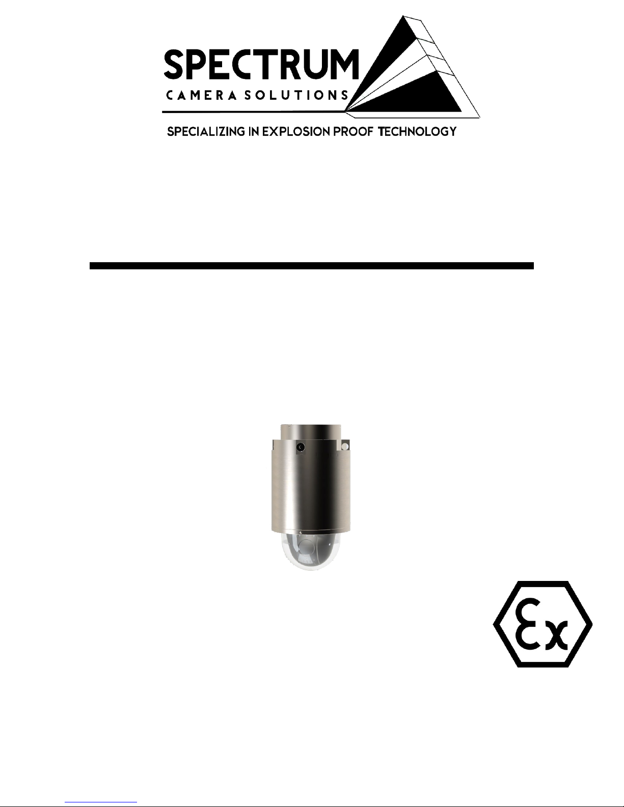
D201-S-Q6055-E-BD
Explosion Camera Proof Network Camera
Installation Manual
1
105607312018 D201-x-Q6055-E
INSTALLATION MANUAL REV-1
Page 2

This pageintentionallyleft blank
2105607312018 D201-x-Q6055-E
INSTALLATION MANUAL REV-1
Page 3
Information in this document is subject to change without notice. All terms
mentioned in this manual that are known to be trademarks have been
appropriately capitalized. Spectrum Camera Solutions LLC acknowledges
all trademark(s) and the rights of the trademark(s) owned by the company
referred to herein.
Release Date:08/30/2018
Document Name D201-S-Q6055-E-BD
© Copyright 2018 by Spectrum Camera Solutions LLC All rights
reserved
Revision Record
Rev. Description Date
0 Initial Release
Aug 30, 2018
1 Updated
Oct 10, 2018
3
105607312018 D201-x-Q6055-E
INSTALLATION MANUAL REV-1
Page 4

Copyright Notice:
This document contains information proprietary to Spectrum Camera Solutions LLC
with all rights reserved worldwide. Any reproduction or disclosure of this publication,
or any part thereof, to persons other than Spectrum Camera Solutions, Inc.
personnel or customers is strictly prohibited, except by written permission of
Spectrum Camera Solutions, Inc. Unauthorized use, disclosure, reproduction, or
translation of this publication will result in Spectrum Camera Solutions, Inc.
exercising maximum possible legal action against all persons and / or organizations
involved.
Disclaimer:
Spectrum Camera Solutions LLC makes no representations or warranties with
respect to the contents hereof. Further, Spectrum Camera Solutions LLC reserves
the right to revise this publication and to make changes in the content hereof, without
obligation to notify any person or organization of such revision or changes.
Patent Notice:
Manufactured under United States US Patent 9917428
Trademark Information:
Spectrum Camera Solutions LLC and its logo(s) are trademark(s) of Spectrum
Camera Solutions LLC.
4
105607312018 D201-x-Q6055-E
INSTALLATION MANUAL REV-1
Page 5
Table of Contents
Legal Notices and Revision History Inside front cover
5
Page
DESCRIPTION 6
MODEL MATRIX 7
LABELS 8
STANDARDS AND CERTIFICATIONS 9
DOCUMENT SYMBOLS 10
HOW TO USE THIS MANUAL 11
GENERAL SAFETY AND OPERATING INFORMATION 12-14
SPECIFICATIONS 15-17
INSTALLATION 18-24
DIMENTIONAL GENERAL ASSEMBLY 25
HARDWARE BOM 26
DISMANTLING & MAINTENANCE 27
MOUNTING OPTIONS 28-33
105607312018 D201-x-Q6055-E
INSTALLATION MANUAL REV-1
Page 6

6
The “D” Series includes a full range of Stainless Steel or Anodized Aluminum camera stations
specifically designed for Hazardous Area Applications.
Spectrum’s D Series is the first Class I Division 1 rated dome style explosion proof housings,
and utilizes the most robust and advanced camera technologies available. The D Series was
designed with the integrator in mind and offers features never before seen in current camera
systems. The solution is Patented with features including a uniform constructed enclosure
consisting of an integrated junction box milled directly to the camera housing. This eliminates
the need for extra equipment, reduces installation time, reduces labor expenses, and increases
safety by lessening the potential for mismatched hazardous rated components. Additionally,
the D Series are constructed with a proprietary explosion resistant polymer blend offering
maximum clarity and enhance optical performance. To enhance optical performance, the
explosion proof lens is equipped with our Virtual Wiper Nano Technology. The series are
available in anodized aluminum or 316L Stainless steel ensuring protection against rain, dust
and corrosion within a wide temperature range between --20°C to 55°C. This feature
ensures operation under extreme weather conditions and hazardous environments. It is
suitable for monitoring wide open indoor/outdoor spaces such as refineries, wellheads,
pipelines, offshore installations, remote and harsh locations where high-level reliability and
precision are always required.
DESCRIPTION
105607312018 D201-x-Q6055-E
INSTALLATION MANUAL REV-1
Page 7
Option A- Model Matrix- D100-D500*
D(N)(XX)-(1)-(CCCCCC)-BD
N=(1) HOUSING LENGTH=3.32 in
N=(2) HOUSING LENGTH=7.75 in
N=(3) HOUSING LENGTH=4.5 in
N=(4) HOUSING LENGTH=5 in
N=(5) HOUSING LENGTH= 5.5 in
XX= 01-99 IEC/EN/UL 60950-1, IEC/EN/UL 62368-1, IEC/EN/UL 60950-22 Internal
Equipment Manufacturer Code**
1= (A) Aluminum Housing with SS 316L Dome Ring
1= (S) Stainless Steel 316L Housing
C= Internal Equipment Part Number from Manufacturer***
BD= Optional Breather drain model****
*Internal components and D Series must be approved by Spectrum
**Internal Equipment Manufacturer Code below
***Must be approved and verified by Spectrum
****Models supplied with Breather Drains will have IP66 ingress protection level
CODE “XX”
Manufacture
01
AXIS COMMUNICATIONS
7105607312018 D201-x-Q6055-E
INSTALLATION MANUAL REV-1
Page 8
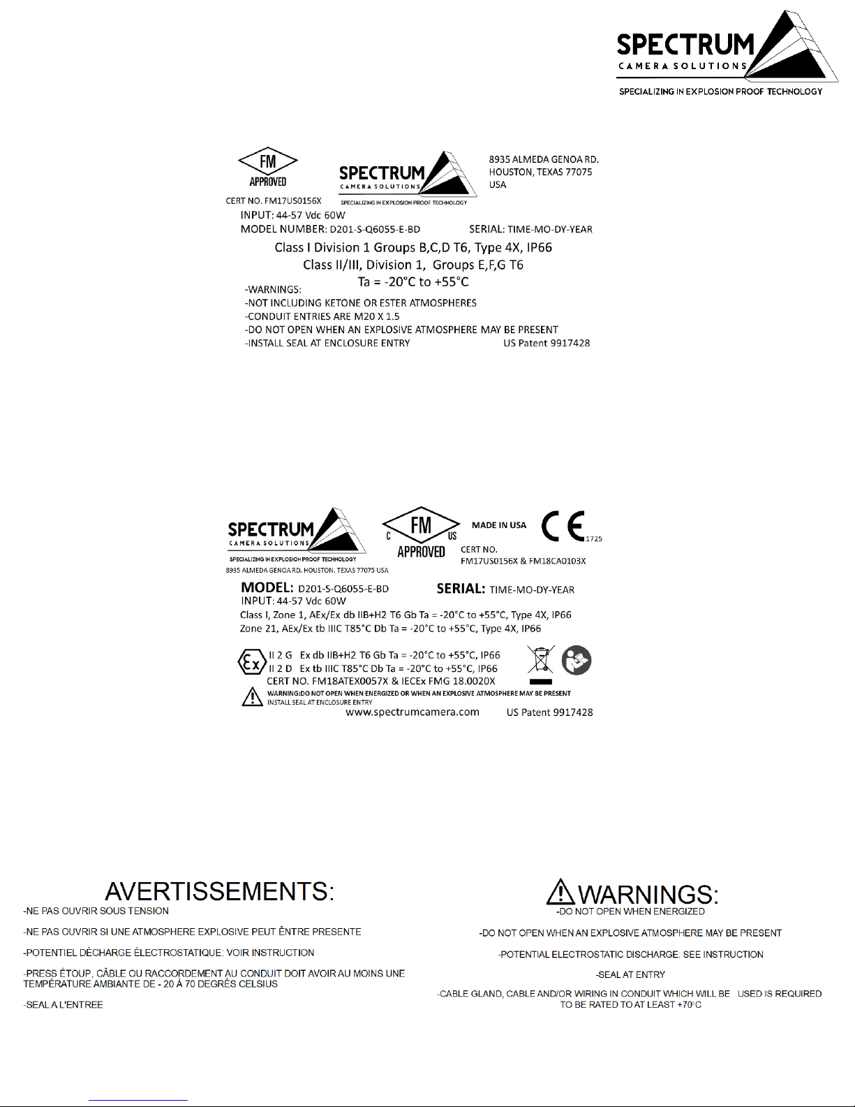
Labels
8
BREATHER DRAIN MODEL
BREATHER DRAIN MODEL
105607312018 D201-x-Q6055-E
INSTALLATION MANUAL REV-1
Page 9

STANDARDS & CERTIFICATIONS
9
STANDARDS-
The equipment is manufactured in accordance with the IECEX scheme, the ATEX Directive 2014/34/EU and
with the following standards :
IEC 60079-0:2011
IEC 60079-1:2014
IEC 60079-31:2013
IEC 60529:2013
EN 60079-0:2012 + A11:2013
EN 60079-1:2014
EN 60079-31:2014
EN 60529:1991 + A1:2000 + A2:2013
ANSI/ISA 60079-0:2013
ANSI/UL 60079-1:2015
ANSI/ISA 60079-31:2015
ANSI/IEC 60529:2004
CAN/CSA-C22.2 No. 60079-0:2015
CAN/CSA-C22.2 No. 60079-1:2016
CAN/CSA-C22.2 No. 60079-31:2015
CAN/CSA-C22.2 No. 60529:2016
Specific Conditions of Use:
-The flameproof joints of the equipment are not intended to be repaired. Consult the manufacturer if dimensional
information on the flameproof joints is necessary.
-Follow the manufacturer’s instructions to reduce the potential of an electrostatic charging hazard on the surface
of the equipment in Group II and III environments.
-The equipment meets the requirements according to the low level risk of mechanical danger. Therefore, the
equipment shall be located and installed such that the risk of impact or other mechanical damage is reduced or
avoided.
NOTE: Use a clean cloth dampened with pure water for cleaning.
CERTIFICATIONS-
CERT NO. FM17US0156X & FM18CA0103X
Class I Division 1 Groups B,C,D T6, Ta = -20°C to +55°CType 4X, IP66/67
Class II/III, Division 1, Groups E,F,G T6 Type 4X, IP66/67 Ta = -20°C to +55°C
Class I, Zone 1, AEx/Ex db IIB+H2 T6 Gb Ta = -20°C to +55°C, Type 4X, IP66/67
Zone 21, AEx/Ex tb IIIC T85°C Db Ta = -20°C to +55°C, Type 4X, IP66/67
CERT NO. FM18ATEX0057X & IECEx FMG 18.0020X
II 2 G Ex db IIB+H2 T6 Gb Ta = -20°C to +55°C, IP66/67
II 2 D Ex tb IIIC T85°C Db Ta = -20°C to +55°C, IP66/67
105607312018 D201-x-Q6055-E
INSTALLATION MANUAL REV-1
Page 10
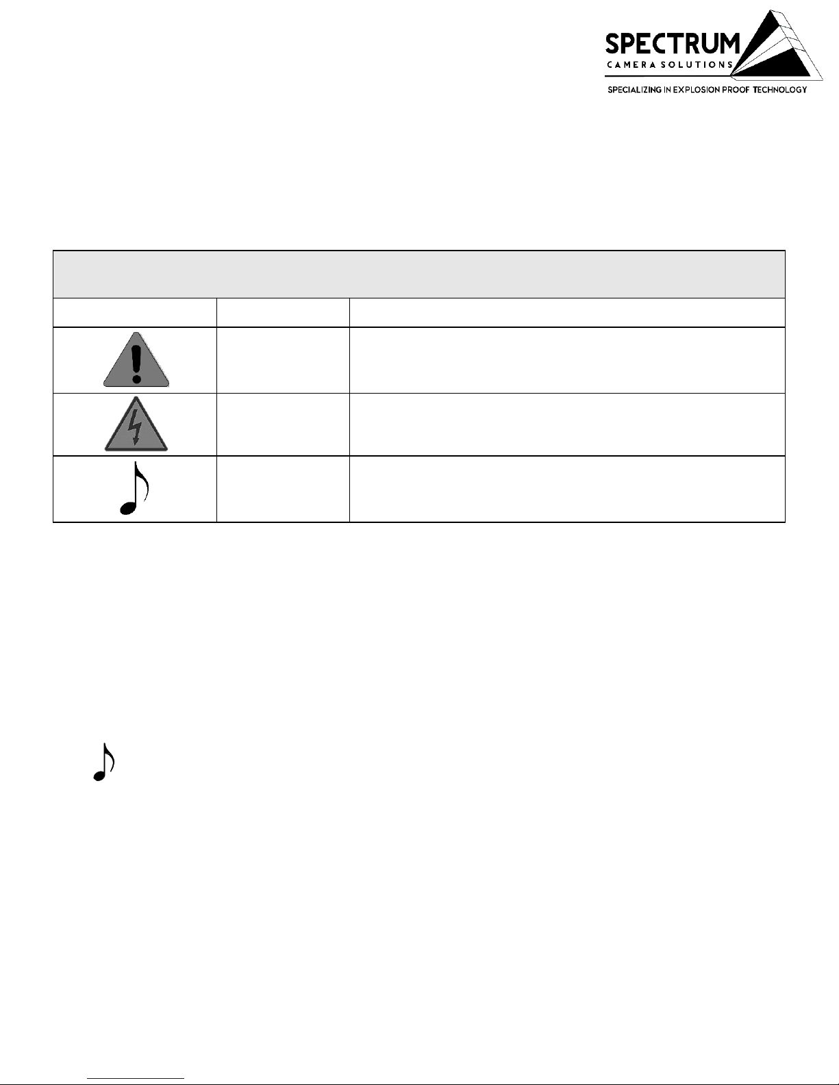
The following symbols are used throughout this manual to alert users to potential
hazards or important information. Failure to heed the warnings and cautions listed
herein can lead to injury and equipment damage.
Symbol Label Description
WARNING:
Consists of conditions, practices, or procedures that
must be observed to prevent personal injury and/or
equipment damage.
CAUTION:
Risk of electric shock or high temperature parts may
result in injury if proper precautions are not taken.
NOTE:
Emphasizes important or essential information.
Locating Information:
NOTE: In the interest of completeness, manuals and drawings included with
the system may provide information pertaining to options not included with
your equipment. Information in application notes supersedes general
information in these documents. Information can be located in this manual
using any of the following aids.
10
DOCUMENT SYMBOLS
105607312018 D201-x-Q6055-E
INSTALLATION MANUAL REV-1
Page 11
How to use this Manual
Safety Considerations:
This information that must be read and understood by all persons installing,
using, or maintaining this equipment. This manual is designed to aid
personnel in the correct and safe installation, operation, and maintenance of
the systems described. Personnel must consider all actions and procedures
for potential hazards or conditions that may not have been anticipated in the
written procedures. If a procedure cannot be performed safely, it must not be
performed until appropriate actions can be taken to ensure the safety of
equipment and personnel. The procedures in this manual are not designed to
replace or supersede required or common sense safety practices. All safety
warnings listed in any documents applicable to equipment and parts used in
or with the system described in this manual must be read and heeded before
commencing work on any part of the system.
NOTE: Refer to all ATEX, CSA, IECEx, NEC, NFPA and FM certificates
for any Special Conditions of Use. If the sign “X” is placed after the
certificate number, it indicates that the equipment or protective
system is subject to special conditions for safe use specified in the
schedule of the certificate.
NOTE: Review all material and safety information in this manual and
install in accordance with this document and all other applicable
ATEX, CSA, IECEx, NEC, NFPA70 Installation Methods and FM and
National standards.
Warning- Failure to follow appropriate safety procedures or
appropriate use of the equipment described in this manual can lead to
injury of personnel or equipment damage.
WARNING – EXPLOSION HAZARD – Do not open equipment
unless power has been removed or the area is known to be nonhazardous.
General Manual:
This manual is intended to be used in conjunction with installed equipment
manual from internal equipment manufacturer.
Note: In the event of a conflict between the requirements of this general
installation manual and the internal equipment manual, the safety and
installation procedures described in this manual shall take precedence.
11
105607312018 D201-x-Q6055-E
INSTALLATION MANUAL REV-1
Page 12

General safety and operating information applicable to electrical equipment installed within
hazardous locations. This information must be understood by all persons installing, using, or
maintaining the electrical equipment. This information is designed to aid personnel in safe
installation, operation, and maintenance of the "D" Series equipment. It is not designed to replace or
limit appropriate safety measures applicable to work performed by personnel. Any additional safety
and operating measures that are required must be determined by and followed by personnel
performing work on the electrical equipment.
WARNING: Deviation from the specified instructions or procedure steps can result
in injury to personnel, equipment malfunction or equipment damage.
WARNING: Return unit to factory for any repairs or replacement of parts, customer
not permitted to repair. This will void all warranties and hazardous area
certification(s) if non-authorized repair occurs.
General Precautions:
Slip resistant gloves and protective eyewear (glasses with side shields or goggles as appropriate)
should be worn when installing and servicing any part of electrical equipment. Hot components
should be allowed to cool before servicing if possible. Other appropriate equipment or clothing must
be used as required by the type of work performed. All applicable regulations and procedures must
be followed for the work performed. Before beginning any work on the equipment, carefully consider
all the potential hazards and ensure that appropriate measures are taken to prevent injury to
personnel or equipment damage.
CAUTION: Electrical equipment components may be hot even when power is
not applied. Take appropriate precautions to prevent injury from contact with hot
items.
12
WARNING:
NEVER open the main housing of the "D" Series unless
authorized and trained and certified to do so
The main housing is manufactured in a controlled environment that eliminates
moister at the factory and is only to be opened by factory certified technicians at an
authorized repair facility. Opening of the main housing will void all warranties.
CAUTION: Failure to allow adequate cooling of electrical equipment components
with hot surfaces before opening the enclosure can lead to injury of personnel or
equipment damage.
General Safety and Operating Information:
105607312018 D201-x-Q6055-E
INSTALLATION MANUAL REV-1
Page 13

Electrical Power:
The "D" Series IP cameras operate from a variety of power options including IEEE compliant POE devices.
• The power supply used with this product shall fulfill the requirements for Safety Extra Low
Voltage (SELV) and Limited Power Source (LPS) according to IEC/EN/UL 62368-1 or
IEC/EN/UL 60950-1 or Listed Class II Power Source Equipment. The product shall be
grounded either through a shielded network cable (STP) or other appropriate method.
Camera Location:
The "D" Series IP camera must be installed in a suitable location away from impacts, heavy vibration and
extreme heat. The "D" Series camera
must not be installed in an area classification for which it is not rated.
The "D" Series camera must be attached securely and appropriately to a wall or supporting structure.
CAUTION: The electrical cover should never be removed unless
power is removed (for at least 5 minutes) from the unit or the area is
known not to contain explosive materials.
13
WARNING
• The product shall be installed by a trained professional.
• The product shall be used in compliance with local laws and regulations.
• Store the product in a dry and ventilated environment.
• Avoid exposing the product to shocks or heavy pressure.
• Do not install the product on unstable brackets, surfaces or walls.
• Use only applicable tools when installing the product. Using excessive force with power tools
could cause damage to the product.
• Do not use chemicals, caustic agents, or aerosol cleaners.
• Use a clean cloth dampened with pure water for cleaning.
• Use only accessories that comply with the technical specification of the product. These can be
provided by Spectrum or a third party.
NOTE:
General Safety and Operating Information:
105607312018 D201-x-Q6055-E
INSTALLATION MANUAL REV-1
Page 14

Installation:
The installation must be realized in accordance with IEC/EN 60079-14 and/or in accordance
with the national requirements. This equipment must be installed and used only by qualified
personnel, having knowledge concerning electrical equipment for use in potentially
explosive areas containing gas and/or dust. Qualified personnel must have knowledge
regarding the types of explosion protection. This equipment is intended to be used in zone 1,
2, 21 and 22 for groups IIB+H2 and IIIC with temperature class T6 or T85°C, it is necessary to
verify if this equipment is in accordance with the atmosphere where it is installed.
Connections:
Electric parameters power control unit Maximum supply voltage: POE+ IEEE 802.3at/af
The terminals are suitable to receive: Solid wires Stranded wires.- *See wiring Diagram
Page
Cable Glands:
The cable entry must be made in order not to alter the specific properties of terminal housing
compartment. The connection to the external circuits must be realized by cable glands or
pipe fittings covered by a separate certificate(s). If a cable gland is not used, or an entry is
open, the entry must be closed by a stopping plug covered by a separate certificate. The
diameter of the cable gland is cylindrical ISO M20 x 1.5.
This equipment can be used with different voltage and power, the nominal parameters are
specified in the manual.
Cable: cable must be tested and certified for temperatures of 70°C or higher.
Fiber Cable: Use a suitably certified optical fiber cable and internal connections shall comply
with requirements of IEC/EN 60079-15
Equipment Modifications:
This equipment must be installed and used in strict accordance with the instructions given in the
user documentation. This equipment contains no user-serviceable components. Unauthorized
equipment changes or modifications will invalidate all applicable regulatory certifications and
approvals.
14
General Safety and Operating Information:
105607312018 D201-x-Q6055-E
INSTALLATION MANUAL REV-1
Page 15

SPECIFICATIONS
Environmental Conditions
(Equipment must be powered)
OPERATIONONAL CONDITIONS
USE
For Indoor and Outdoor Use
15
CERTIFICATIONS of Model- D201-S-Q6055-E-BD
CERT NO. FM17US0156 & FM18CA0103X
Class I Division 1 Groups B,C,D T6, Ta = -20°C to +55°C Type 4X, IP66
Class II/III, Division 1, Groups E,F,G T6 Type 4X, IP66/67 Ta = -20°C to +55°C
Class I, Zone 1, AEx/Ex db IIB+H2 T6 Gb Ta = -20°C to +55°C, Type 4X, IP66
Zone 21, AEx/Ex tb IIIC T85°C Db Ta = -20°C to +55°C, Type 4X, IP66
CERT NO. FM18ATEX0057X & IECEx FMG 18.0020X
II 2 G Ex db IIB+H2 T6 Gb Ta = -20°C to +55°C, IP66
II 2 D Ex tb IIIC T85°C Db Ta = -20°C to +55°C, IP66
ELECTRICAL REQUIREMENTS of Model- D201-S-Q6055-E-BD
POWER
INPUT/CONSUMPTION
CAMERA CONSUMPTION: TYPICAL 16W, MAX 60W
Voltage 44-57 Vdc 60W over 4-pairs
105607312018 D201-x-Q6055-E
INSTALLATION MANUAL REV-1
Page 16

D201-S-Q6055-E-BD Series Casing Material Specifications
316L STAINLESS STEEL 62lbs
NOTE: Spectrum Camera Solutions, LLC is NOT responsible for any misuse
or improper installation of product, assumes no liability for special or
consequential damages caused by use or misuse or improper installation of
its products sold and assumes no liability for injury from use or misuse or
improper installation of its products or attached products.
D201-S-Q6055-E-BD Explosion Proof
Camera Hazardous Area
Voltage Material Model Number
IEEE 802.3bt / PoE++ / 60W
PoE Midspans/PoE Injectors
316L STAINLESS STEEL D201-S-Q6055-E-BD
16
SPECIFICATIONS
Power Source Specification For D201-S-Q6055-E-BD
AXIS T8154 60 W SFP Midspan
105607312018 D201-x-Q6055-E
INSTALLATION MANUAL REV-1
Page 17

17
WIRING ENTRIES
Conduit Entries are M20 x 1.5 Use appropriate Adapter
With Nylon Washer or O-ring to keep ingress protection
CAUTION: Ensure the Ethernet cable is disconnected from power source prior to wiring to
the terminal block
105607312018 D201-x-Q6055-E
INSTALLATION MANUAL REV-1
Page 18

CAUTION: Ensure the Ethernet cable is disconnected from power
source prior to wiring to the terminal block
18
Ensure that power is off before attempting to connect and wire the camera
1. Use supplied M6 Hex tool to unscrew bolts and lock washers supplied on camera
2. Make sure threads on camera and M10x 1.5 are free of dirt and debris. Place mount on camera
and align holes and tighten bolts
3. Attach the camera with wall mount to mounting surface. Use only installation methods and
materials capable of supporting four times the maximum specified load of the system
Figure 1. wall bracket installation
INSTALLATION
105607312018 D201-x-Q6055-E
INSTALLATION MANUAL REV-1
Page 19

19
4. Use supplied M5 supplied Hex tool to loosen D1005 terminal cap by turning counterclockwise
5. Set D1005 terminal cap in safe place
6. Route cable(s) into D1006 terminal housing junction box through user-supplied cable gland and
seal using the recommended gland installation practices. There are two conduit entries on models
without the-BD Breather drain option.
Figure 2. Removing D1005 terminal cap
Conduit Entries are M20 x 1.5 Use appropriate Adapter with Nylon Washer
or O-ring to keep ingress protection follow guidelines of the manufacturer of
gland or adapter
INSTALLATION
105607312018 D201-x-Q6055-E
INSTALLATION MANUAL REV-1
Page 20

20
Conduit Entries are M20 x 1.5 Use appropriate Adapter
With Nylon Washer or O-ring to keep ingress protection
Example of CMP M20 to
3/4NPT adapter with Nylon
Washer
INSTALLATION
CAUTION: Ensure the Ethernet cable is disconnected from power
source prior to wiring to the terminal block
Figure 3.
Figure 4.
105607312018 D201-x-Q6055-E
INSTALLATION MANUAL REV-1
Page 21

21
7. Connect the wiring using installer supplied small screw driver to push the open terminal block
contact. Insert wires and remove screw driver. Adhere to local electrical codes/laws.
Power Connection To "D" Series Camera
TERMINAL NUMBER WIRE
Position - 1 White-Orange
Position - 2 Orange
Position - 3 White-Green
Position - 4 Blue
Position - 5 White-Blue
Position - 6 Green
Position - 7 White-Brown
Position - 8 Brown
Table 1.
Figure 5. Wire/Cable Connections
INSTALLATION
105607312018 D201-x-Q6055-E
INSTALLATION MANUAL REV-1
Page 22

8. In addition to the internal ground connection, this equipment is also provided by an external
secondary ground connection. Both must be connected for the internal ground the section must be
equal to the active conductors. The external ground can receive a wire of 4 mm. The user/installer
must connect the internal and external earthing before powering. STP cable connection with earthing
in camera junction box. The earth wire is the screen of the cable, to be isolated in the wiring terminal
junction box size Green Thread-forming Bonding Screw, M5 x 15mm
22
External
Ground
Internal
Ground
Figure 6. Grounding
INSTALLATION
105607312018 D201-x-Q6055-E
INSTALLATION MANUAL REV-1
Page 23

23
9. Ensure threads on D1005 terminal cap and D1006 Terminal housing are free of dirt and debris.
10. Ensure gasket is free of dirt and debris
11. Reinstall D1005 terminal cap using supplied M5 supplied Hex tool to tighten by turning
clockwise until hand tight and gasket is seated
12. In the following order install D2005 housing retainer clip, wedge lock washers, and nut. Ground
lug is at bottom of thread adapter See figure 8-9
Figure 7. Installing D1005 cap
Figure 8. Retaining clip order
Figure 9. Final assembly
INSTALLATION
105607312018 D201-x-Q6055-E
INSTALLATION MANUAL REV-1
Page 24

24
NOTE: Do not install camera unless power is applied in near future.
13. Remove Protective film after installation. If protective film is not removed in timely manor
damage to dome is likely to occur with UV exposure
14. Apply power. For internal equipment startup procedures, setting changes, and troubleshooting
guides reference the camera manufacturer’s manual included with the "D" Series Cameras. If the
included copy is lost please contact https://www.spectrumcamera.com/support or To obtain
assistance, please go to https://www.axis.com/support
INSTALLATION
105607312018 D201-x-Q6055-E
INSTALLATION MANUAL REV-1
Page 25

Dimensional General Assembly:
25105607312018 D201-x-Q6055-E
INSTALLATION MANUAL REV-1
Page 26

26
HARDWARE BOM
41
3
2
5
1- (QTY 1)EXTERNAL GROUND LUG
2- (QTY 3)M10 X 1.5 18-8 BOLT
3- (4 SETS) WEDGE LOCK WASHER
4- (QTY 1)D2005 Z-CLIP
5- SD-WM (WALL MNT. NOT INCLUDED)
6- M10X1.25 M10X1.5 ADAPTER
6
105607312018 D201-x-Q6055-E
INSTALLATION MANUAL REV-1
Page 27

Dismantling:
It is not recommended to open the main camera housing. All repairs of explosion-proof
equipment must be made according the specified criteria of IEC/EN 60079-19 rule by qualified
personnel, having knowledge concerning electrical equipment for potentially explosive areas
containing gas and/or dust. Qualified personnel must have knowledge regarding the types of
explosion protection.
Maintenance:
The maintenance must be realized in accordance with IEC/EN 60079-17 and/or in accordance
with the national requirements. Contact Spectrum Camera for training program to properly
open and close the main camera housing.
Cleaning lens- Washdown dome with water first to avoid partials scratching the surface. Clean
lens with damp microfiber cloth with mild dish soap and water. Lastly, apply coating of Repel (by
Unelko corporation) surface cleaner. Never use harsh chemicals or abrasive towels.
Replacing the battery- The Axis Q6055-E product uses a *Panasonic 3.0 V BR2032 lithium
battery Lithium primary battery composed of cathode from carbon monofluoride anode from
lithium and electrolyte from organic solvent and lithium salt as the power supply for its internal
real-time clock (RTC). Under normal conditions this battery will last for a minimum of five years.
Low battery power affects the operation of the RTC, causing it to reset at every power-up. When
the battery needs replacing, a log message will appear in the product’s server report. For more
information about the server report, see the product´s setup pages or contact Spectrum support.
The battery should not be replaced unless required, but if the battery does need replacing,
contact Spectrum support at
www.spectrumcamera.com/support for assistance or To obtain
assistance, please go to https://www.axis.com/support.
This battery is not field replaceable*.
27
DISMANTLING & MAINTENANCE
105607312018 D201-x-Q6055-E
INSTALLATION MANUAL REV-1
Page 28

SD-WM WALL MOUNT
28105607312018 D201-x-Q6055-E
INSTALLATION MANUAL REV-1
Page 29

SD-PMA POLE MOUNT ADAPTER
29
HARDWARE
QTY 4 7/8-20 18-8 Bolts
QTY 2 12in all thread with nuts and washers
QTY 2 A1612 sides
105607312018 D201-x-Q6055-E
INSTALLATION MANUAL REV-1
Page 30

SD-CM CORNER MOUNT
30
HARDWAREQTY 4 7/8-20 18-8 Bolts
105607312018 D201-x-Q6055-E
INSTALLATION MANUAL REV-1
Page 31

SD-VM VIBRATION MOUNT
31
HARDWAREQTY 4 7/8-20 18-8 Bolts
FRONT
105607312018 D201-x-Q6055-E
INSTALLATION MANUAL REV-1
Page 32

SD-SO STANDOFF MOUNT
32
HARDWAREQTY 4 7/8-20 18-8 Bolts
FRONT
BACK
105607312018 D201-x-Q6055-E
INSTALLATION MANUAL REV-1
Page 33

ASSEMBLY MOUNTS
33
SD-CM+SD-PMA
SD-CM+SD-VM+SD-SO+ SD-PMA
105607312018 D201-x-Q6055-E
INSTALLATION MANUAL REV-1
Page 34

EU Declaration of Conformity
Spectrum Camera Solutions,
LLC
Spectrum Camera Solutions declares that under our sole responsibility that the product (s)
listed below conform to the relevant provisions of 2014/34/EU of August 29, 2018
Doc No. 100108292018 2014/34/EU Spectrum Camera Solutions, LLC 8935 Almeda Genoa Rd. Houston, TX
77075
Notified Body
FM Approvals Ltd. 1 Windsor Dials,
Windsor, Berkshire, UK. SL4 1RS
Product(s) Network Ethernet Cameras
Model numbers D Series
Dab-c-d-e. Network Ethernet Camera.
a = Housing length 1, 2, 3, 4 or 5 (or any three digits from 084 to 196 representing custom housing
lengths in mm).
b = Camera manufacturer code (two digits) 01 to 99.
c = Material A or S.
d = Several characters representing the camera manufacturer’s part number (may contain additional
dashes).
e = Optional breather/drain BLANK or BD. (IP67 is not applicable when supplied with optional
breather/drain).
Markings II 2 G Ex db IIB+H2 T6 Gb Ta = -20°C to +55°C
II 2 D Ex tb IIIC T85°C Db Ta = -20°C to +55°C
Ratings The D Series Network Ethernet Cameras can be supplied with a variety of cameras (in accordance
with EN 60950 or EN 62368) complying with the IEEE 802.3af, 802.3at, 802.3at++ or 802.3bt PoE (Power
over Ethernet) standard (57Vdc max). Voltage and wattage shall not exceed the maximum tested
configuration of 57Vdc (60W). The D Series Network Ethernet Cameras are rated for use in an ambient
temperature range of -20°C to +55°C and are IP66/67 (IP67 is not applicable when supplied with optional
breather/drain). The camera within the enclosure may be placed in any arrangement provided that an area
of at least 40% of each cross-sectional area remains free to permit unimpeded gas flow and, therefore,
unrestricted development of an explosion. Separate relief areas may be aggregated provided each area has
a minimum dimension in any direction of 12.5mm.
Compliance with the Essential
Health and Safety Requirements
has been assessed by reference to
the following Standards
EN 60079-0:2012 + A11:2013, EN 60079-1:2014, EN 60079-31:2014,
EN 60529:1991 + A1:2000 + A2:2013
Factory/Manufacturing Location 8935 Almeda Genoa Rd. Building B Houston Texas 77075
Conformity has been
demonstrated with reference to
the following documentation:
EU Type Examination Certificate (FM18ATEX0057X - 0)
Quality Assurance Notification FM17ATEXQ0099
Hubert Lee Rice II
CEO
Date: August 29, 2018
Doc No. 100108292018
2014/34/EU
Page 35

Attestation of Conformity
Spectrum Camera Solutions,
LLC
Spectrum Camera Solutions declares that under our sole responsibility that the product (s)
listed below conform to the relevant provisions of 2014/34/EU of August 29, 2018
Doc No. 100108292018 2014/34/EU Spectrum Camera Solutions, LLC 8935 Almeda Genoa Rd. Houston, TX
77075
Notified Body
FM Approvals Ltd. 1 Windsor Dials,
Windsor, Berkshire, UK. SL4 1RS
Product(s) Network Ethernet Cameras
Model numbers D Series
Dab-c-d-e. Network Ethernet Camera.
a = Housing length 1, 2, 3, 4 or 5 (or any three digits from 084 to 196 representing custom housing
lengths in mm).
b = Camera manufacturer code (two digits) 01 to 99.
c = Material A or S.
d = Several characters representing the camera manufacturer’s part number (may contain additional
dashes).
e = Optional breather/drain BLANK or BD. (IP67 is not applicable when supplied with optional
breather/drain).
Markings II 2 G Ex db IIB+H2 T6 Gb Ta = -20°C to +55°C
II 2 D Ex tb IIIC T85°C Db Ta = -20°C to +55°C
Ratings The D Series Network Ethernet Cameras can be supplied with a variety of cameras (in accordance
with EN 60950 or EN 62368) complying with the IEEE 802.3af, 802.3at, 802.3at++ or 802.3bt PoE (Power
over Ethernet) standard (57Vdc max). Voltage and wattage shall not exceed the maximum tested
configuration of 57Vdc (60W). The D Series Network Ethernet Cameras are rated for use in an ambient
temperature range of -20°C to +55°C and are IP66/67 (IP67 is not applicable when supplied with optional
breather/drain). The camera within the enclosure may be placed in any arrangement provided that an area
of at least 40% of each cross-sectional area remains free to permit unimpeded gas flow and, therefore,
unrestricted development of an explosion. Separate relief areas may be aggregated provided each area has
a minimum dimension in any direction of 12.5mm.
Compliance with the Essential
Health and Safety Requirements
has been assessed by reference to
the following Standards
EN 60079-0:2012 + A11:2013, EN 60079-1:2014, EN 60079-31:2014,
EN 60529:1991 + A1:2000 + A2:2013
Factory/Manufacturing Location 8935 Almeda Genoa Rd. Building B Houston Texas 77075
Conformity has been
demonstrated with reference to
the following documentation:
EU Type Examination Certificate (FM18ATEX0057X - 0)
Quality Assurance Notification FM17ATEXQ0099
Hubert Lee Rice II
CEO
Date: August 29, 2018
Doc No. 100108292018
2014/34/EU
 Loading...