

Page 1
Assembly Instructions
Important
Before you begin, read and comply with all safety and operating instructions,
and ensure all parts and correct quantities are included.
Any parts damaged during shipment must be reported within 5 days of receipt. To
report information regarding missing parts or damage, to purchase parts or accessories, or if you have any questions, please contact us.
www.spectrumfurniture.com
800-235-1262, 715-723-6750
Thank you for purchasing Spectrum products!
Assembly Tips:
• Assemble the console in its nal location.
• To facilitate assembly, keep the fasteners nger-tight until the
console is completely together. Then tighten securely.
Note: The items below represent all the structural components
available for the Instructor Media Console. Due to the various
console congurations and order combinations available, some
of the items shown here may not be included with your particular
unit, and some assembly steps may not apply. Before beginning
assembly, please review these instructions.
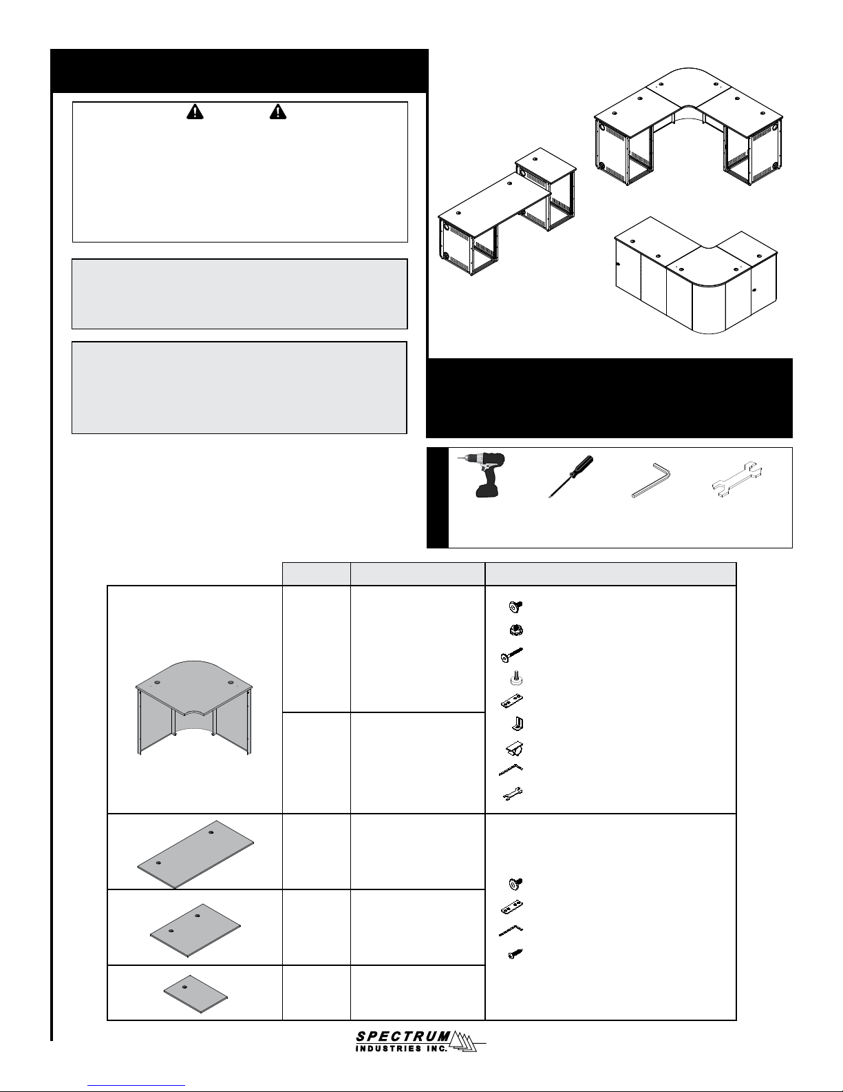
Instructor Media Console
68XXX series
Drill with
Phillips driver
Tools Required
(best)
Product # Description Hardware
68156 36” Radius Corner
68106 29” Radius Corner
68202 Triple Worksurface
68201 Double Worksurface
Phillips
screwdriver
(26) 1/4-20 x 15mm JC bolt - 052605
(6) 1/4-20 Flanged locknut - 0108896
(2) 1/4-20 x 50mm JC bolt - 038047
(2) 5/16-18 x 1” Glide - 037779
(2) Unit-to-unit bracket - 037749
(2) Worksurface bracket - 044069
(3) Cord clip - 044207
(1) 4mm Hex wrench - 025039
(1) Glide wrench - 025069
(4) 1/4-20 x 15mm JC bolt - 052605
(2) Unit-to-unit bracket - 037749
(1) 4mm Hex wrench - 025039
(6) #6 x 5/8” PHSM screws - 025044
4mm Hex
Wrench
(included)
Glide Wrench
(included when
applicable)
68200 Single Worksurface
0108630R11 Page 1 of 10
Page 2
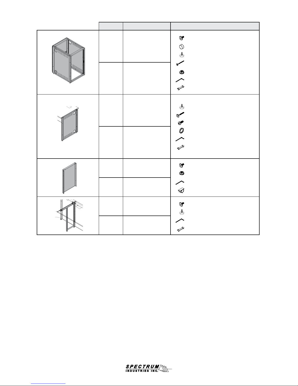
Product # Description Hardware
(4) 1/4-20 x 15mm JC bolt - 052605
68157 36” Equipment Rack
68107 29” Equipment Rack
(2) Adhesive bumper - 044573
(4) 5/16-18 x 1” Glide - 037779
(1) 1/4-20 x 90mm JC bolt - 039065
(1) 1/4-20 Flanged locknut - 0108896
(1) 4mm Hex wrench - 025039
(1) Glide wrench - 025069
68155 36” End Support Leg
68105 29” End Support Leg
68151 36” Wall Filler Panel
68101 29” Wall Filler Panel
68154 36” Mid-Support Leg
68104 29” Mid-Support Leg
(2) 5/16-18 x 1” Glide - 037779
(2) 1/4-20 x 40mm JC bolt - 021581
(6) 8-32 x 1/2” PH thread-cutting - 0100167
(2) 4” Snap-in grommet - 0104836
(1) 4mm Hex wrench - 025039
(1) Glide wrench - 025069
(10) 1/4-20 x 15mm JC bolt - 052605
(4) 1/4-20 Flanged locknut - 0108896
(1) 4mm Hex wrench - 025039
(2) Cord clip - 044207
(4) 1/4-20 x 15mm JC bolt - 052605
(2) 5/16-18 x 1” Glide - 037779
(1) 4mm Hex wrench - 025039
(1) Glide wrench - 025069
0108630R11 Page 2 of 10
Page 3
Worksurface Support Guidelines
For adequate support, areas under worksurfaces generally should not
exceed a span of more than 2 open spaces (or wall ller panels) wide.
• When a radius corner is used with two double worksurfaces that have equipment rack support, a mid-support leg usually is not necessary
• When a radius corner is next to a double worksurface, an equipment rack or mid-support leg should be used to support the double worksurface
• When a triple worksurface is specied, at least one equipment rack should be used underneath to provide adequate support
• Mid-support legs are used at the seam two worksurfaces
• End-support legs are used at the end of a worksurface
Radius corner worksurface
Mid-support leg at
Double
worksurface
worksurface connection
Triple worksurface
2 open
spaces
2 open
spaces
2 open
spaces
Triple worksurface
Mid-support leg at
worksurface connection
Triple worksurface
2 open
spaces
0108630R11 Page 3 of 10
Page 4

Assembly / Setup
Radius Corner Assembly
1. Install the (2) glides onto the corner panel. Figure 1A. The glides can be adjusted later to level the console.
2. Attach each wall ller panel to the corner panel with (4) 1/4-20 x 15mm JC bolts.
3. Align and attach the corner worksurface to the wall ller panels with (4) 1/4-20 x 15mm JC bolts. Figure 1B.
Corner panel
Wall ller panel Wall ller panel
Note: Do not tighten fasteners
completely until the unit is together.
3/8” monitor arm
mounting hole
1/4-20 x 15mm
JC bolts
Glides
Figure 1A
Corner worksurface
Note: Monitor arms can be mounted
to the corner worksurface using the
left or right 3/8” mounting holes.
3/8” monitor arm
mounting hole
Figure 1B
0108630R11 Page 4 of 10
Page 5

Equipment Rack Assembly
1. Tip the equipment rack onto its back.
2. Install the (4) glides onto the bottom as shown. Figure 2A. The glides
can be adjusted later to level the console.
3. Tip the unit back upright, and open the rear door to attach the (2)
adhesive bumpers to the equipment rack frame as shown. Figure 2B.
Glide
Adhesive
bumper
Rear door
Adhesive bumper
Figure 2A Figure 2B
Wall Filler Panel Assembly
Panel-to-Equipment Rack Attachment:
1. Align the wall ller panel mounting holes as shown. Figure 3A.
2. Attach with (4) 1/4-20 x 15mm JC bolts. (Locknuts not required.)
Equipment rack
Wall ller panel
1/4-20 x 15mm
JC bolt
(4 required per
connection)
Panel-to-Panel Attachment:
1. To attach two wall ller panels together, align the mounting holes.
2. Attach together with (4) 1/4-20 x 15mm JC bolts and (4) 1/4-20
anged locknuts. Figure 3B.
Wall ller panel
1/4-20 anged
locknut
(4 required per
connection)
1/4-20 x 15mm
JC bolt
(4 required per
connection)
Figure 3A Figure 3B
Wall ller panel
Note: The two holes on top of the
panel are for worksurface attachment.
0108630R11 Page 5 of 10
Page 6

End-Support Leg Assembly
1. Attach the side panel to the leg frame as shown with (6) 8-32 x 1/2” PH thread-cutting screws and tighten securely. Figure 4A.
Note: The 4” grommets will be at the rear of the console.
2. Install the (2) glides onto the bottom of the leg. (The glides can be adjusted later to level the console if necessary.)
3. Align the assembled end-support leg and wall ller panel mounting holes. Figure 4B.
Be sure the wall ller panel overlaps the end-support leg as shown.
4. Attach with (4) 1/4-20 x 15mm JC bolts.
5. Worksurface attaches to the end-support leg with (2) 1/4-20 x 40mm JC bolts.
4” Grommet
Note: End-support legs are used only
at the end of a worksurface (not on a
seam between two worksurfaces).
Side panel setup for
right-side installation
on console (this side
faces inside console, 4”
grommets toward rear)
Leg frame
Open area under
worksurface
Wall ller
panel
Be sure the wall ller
panel overlaps the
end-support leg here.
1/4-20 x 15mm
JC bolt
(4 required per
connection)
Glide
Glide
8-32 x 1/2” PH
thread-cutting screw
(6 required)
Figure 4A
Assembled endsupport leg
Equipment Rack-to-Equipment Rack Connection
1. Place the two equipment racks together as shown. Figure 5.
2. Install (2) 1/4-20 x 90mm JC bolts and (2) 1/4-20 anged locknuts.
3. Do not over-tighten fasteners.
1/4-20 x 90mm
JC bolt
1/4-20 anged locknut
Flush side of panel in endsupport leg facing outward. 4”
grommets toward rear of console.
Figure 4B
1/4-20 anged locknut
1/4-20 x 90mm JC bolt
Figure 5
0108630R11 Page 6 of 10
Page 7

Mid-Support Leg Assembly
1. Install the (2) glides onto the bottom of the leg. The
glides can be adjusted later to level the console.
2. Align the mid-support leg and wall ller panel mounting
holes as shown. Figure 6.
3. Attach the mid-support leg to the wall ller panels with
(4) 1/4-20 x 15mm JC bolts.
4. Set both worksurfaces onto console with the seam
centered over the mid-support leg.
5. Attach to worksurfaces with (4) 1/4-20 x 15mm JC bolts
Note: Mid-support legs are used at the joint connection of two worksurfaces to provide support for two
or more open spaces (or wall ller panels) wide.
Worksurfaces
1/4-20 x 15mm JC bolts
(4 required)
Wall ller
panel
Wall
ller
panel
Mid-support leg
Wall ller
panel
1/4-20 x
15mm JC bolt
(4 required per
connection)
Figure 6
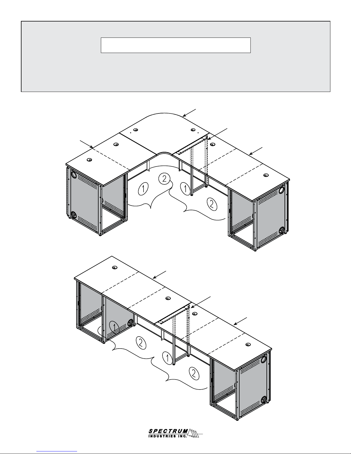
Worksurface Assembly
Worksurface-to-Worksurface connection:
1. Attach the (2) unit-to-unit brackets to one installed worksurface (use inner holes)
with 1/4-20 x 15mm JC bolts. Do not tighten completely. Figure 7A.
2. Set the second worksurface onto the unit-to-unit brackets, and adjacent assembled wall ller panels.
3. Align the worksurface mounting holes with the wall ller panel mounting holes.
4. Attach with 1/4-20 x 15mm JC bolts.
Underside of
worksurface
Unit-to-unit
brackets
Wall ller
panel
Glides
Note: This is the connection between two worksurfaces with open area underneath (no equipment racks).
To provide adequate support, areas under worksurfaces generally should not exceed a span of more than
two open spaces (or wall ller panels) wide.
1/4-20 x 15mm JC bolt
(2 per bracket)
Worksurface
Wall ller
panel
Figure 7A
0108630R11 Page 7 of 10
Page 8

Worksurface-to-top of Equipment Rack:
Worksurface-to-Worksurface with Equipment Rack:
Note: This is the attachment of a worksurface to the top of an equipment rack.
1. Set the worksurface onto the equipment rack and any adjacent
assembled wall ller panels (if applicable). Figure 7B.
2. Align the worksurface and equipment rack mounting holes.
3. Attach worksurface with (4) 1/4-20 x 15mm JC bolts.
Worksurface
Note: This is the connection between a worksurface of equal
height to another worksurface above an equipment rack.
1. Attach each worksurface bracket to the equipment rack with (1)
1/4-20 x 50mm JC bolt and (1) 1/4-20 serrated anged locknut
(attached from inside eq rack). (The slotted side of the bracket will
attach to the worksurface.) Do not tighten completely. Figure 7C.
2. Set the worksurface onto the assembled wall ller panel(s) and
worksurface brackets and align the mounting holes.
3. Attach worksurface with 1/4-20 x 15mm JC bolts.
4. Align the tops of the worksurfaces and tighten all screws securely.
1/4-20 x 50mm JC bolt
(1 per bracket)
Underside of
worksurface
Worksurface
brackets
1/4-20 anged locknut
(1 per bracket-attach
from inside eq rack)
Equipment rack
1/4-20 x 15mm
JC bolt
(4 required)
Figure 7B
Cord Clips
1. Apply cord clips to underside of worksurface where needed
to route and secure cords. Figure 8.
(Clips only included with radius corner and wall ller panels.)
Note: The cord clips provide cord management when cords and
wires are to be routed to the worksurface from under the console.
1/4-20 x 15mm
JC bolt
(1 per bracket)
Wall ller
panel
Equipment rack
Figure 7C
Cord clip
Figure 8
0108630R11 Page 8 of 10
Page 9

Accessories
Not for use on endsupport legs or standalone equipment racks
Clear Acrylic Locking Door
36”H - 68153
29”H - 68103
• For instructor-side installation
• Can be installed to be hinged
from the left or right side
Equipment Rack Bottom Shelf - 68203
• Increases security
• Prevents static electricity and dust build-up
• Includes 4’ grommet at back
Solid Locking Door
36”H - 68152
29”H - 68102
• For instructor-side installation
• Can be installed to be hinged
from the left or right side
Stepped-Height Bracket - 68205
• Connects 29”H console to 36”H
console
Flip-up Shelf - 68204
• Shelf hinges lock into place in the upright position
• Shelf mounts level with worksurface
• Includes 2” grommet
• Mounting plate available in black or dark gray
Weight capacity: 35 lb [15.9 kg]
Dimensions: 21.1875”W [53.8 cm] x 30”D
[76.2 cm] x 1”H [2.54 cm]
Unit weight: N/A
Level-Height Bracket Kit - 68207
• Attaches a worksurface to another worksurface
of equal height over an equipment rack
Econo Keyboard Tray - 95520
• 18.375”W [46.7 cm] x 12”D [30.5 cm]
Wire Management Clips - 68206
• Mounts under worksurface
• Set of 3
Micro-Arm Keyboard Tray - 95506
• Slides in, out, up and down
• 19.75”W x 10”D
Rear Rack Rail Kit
36”H - 68150
29”H - 68100
• Adds 18RU or 14RU to
• Set of 2
rear of equipment rack
Cove Power Module - 99044
• Two power receptacles per module
• Two USB charge ports (not data-compatible)
• Thumbscrew clamps
• Requires worksurface cutout
• ETL listed
• Available in Black or Silver
Cutout required: 5.25”W [13.3 cm] x 2”D [5.1 cm]
Power cord:
Power receptacles: 12A, 120 VAC spill-resistant
USB charging ports: 2.1A (10.5W)
Dimensions:
Unit weight: 2.29 lb [1 kg]
(mounts to surface thicknesses
up to 1.5”)
9’ [274 cm] with 90° at plug with
45° rotation
6”W [15.2 cm] x 2.5”D [6.35 cm] x
3.18”H [8.1 cm]
See spectrumfurniture.com for the latest
accessories and detailed warranty information.
0108630R11 Page 9 of 10
Page 10

Warranty
DESIGNED AND ASSEMBLED IN
CHIPPEWA FALLS
WISCONSIN.USA
WE WILL MAKE IT RIGHT FOR YOU!
Spectrum is committed to provide complete customer satisfaction. Each of our products is manufactured from the best materials available and each
product is stringently monitored throughout the production process through our P.A.C.E. program (Product Assurance to meet Customer Expectations).
We expressly warrant that Spectrum products will be of good quality and workmanship and free from defect for the period set out in the warranty table below
from the date of delivery. This warranty shall not apply to defects or damage resulting from misuse, abuse, neglect, improper care, modifi cation or repair not
authorized by Spectrum, or any other cause outside the control of Spectrum. Spectrum will, at its sole option, either repair or replace the defective product.
This warranty is exclusive; no other warranty, written or oral, is expressed or implied. This warranty is given by Spectrum to Buyer and to no other per-
son or legal entity. No Spectrum dealer, distributor, agent or employee is authorized to make any modifi cation or addition to this warranty.
NOTWITHSTANDING ANYTHING TO THE CONTRARY, SPECTRUM WILL NOT UNDER ANY CIRCUMSTANCES BE LIABLE FOR INDIRECT OR LIQUIDATED DAMAGES, INCLUDING CONSEQUENTIAL, INCIDENTAL AND SPECIAL DAMAGES. IN NO EVENT SHALL SPECTRUM’S LIABILITY, WHETHER
UNDER CONTRACT OR WARRANTY, IN TORT OR OTHERWISE, EXCEED THE PURCHASE PRICE RECEIVED BY SPECTRUM FOR THE PRODUCT AT
ISSUE AND “RECALL ACTION” EXPENSES. SPECTRUM SHALL NOT BE SUBJECT TO ANY OTHER OBLIGATIONS OR LIABILITIES, WHETHER ARISING OUT OF BREACH OF CONTRACT, WARRANTY, TORT (INCLUDING NEGLIGENCE AND STRICT LIABILITY) OR OTHER THEORIES OF LAW, WITH
RESPECT TO PRODUCTS SOLD OR SERVICES RENDERED BY SPECTRUM, OR ANY UNDERTAKINGS, ACTS OR OMISSIONS RELATING THERETO.
Our Customer Service Department is ready to provide immediate attention to any questions, comments or concerns. They are available to answer your calls
Monday through Friday from 7 am to 5 pm CST. In addition your product comments or concerns are welcome via e-mail at: spectrum@spectrumfurniture.com.
Warranty Table
Item
Adjustable Crank / Electric Desk Legs
Flat Panel Desk Gas Cylinders
Chairs
• Adjustable Height Chair Parts – including frames, gas
cylinders, wood and plastic parts, control handles, casters
• Adjustable Height Chair Upholstery
• In-Stock Upholstery
• Graded-In Fabrics and Customer Owned Material
Height Adjustable Columns and Lifts
General Use Casters
Electrical (including timers and LINAK actuators) • 2 Years
Keyboard / Mouse Trays • 1 Year
Flat Panel Monitor Arms
• Flat Panel Monitor Arm – General Parts
• Flat Panel Monitor Arm – Gas Cylinders
Desks and Lecterns
• Computer Desk Chassis
• Cart Chassis
• Lectern Chassis
Warranty Period
effective 1/1/2015
• 1 Year
• 7 Years
• 2 Years
• 2 Years
• No Warranty
• 1 Year
• 5 Years
• 2 Years
• 10 Years
925 FIRST AVENUE, CHIPPEWA FALLS, WI 54729 / 800-235-1262 / 715-723-6750 / WWW.SPECTRUMFURNITURE.COM
© 2016 Spectrum Industries Inc., All rights reserved.
8
0108630R11 Page 10 of 10
 Loading...