

Page 1
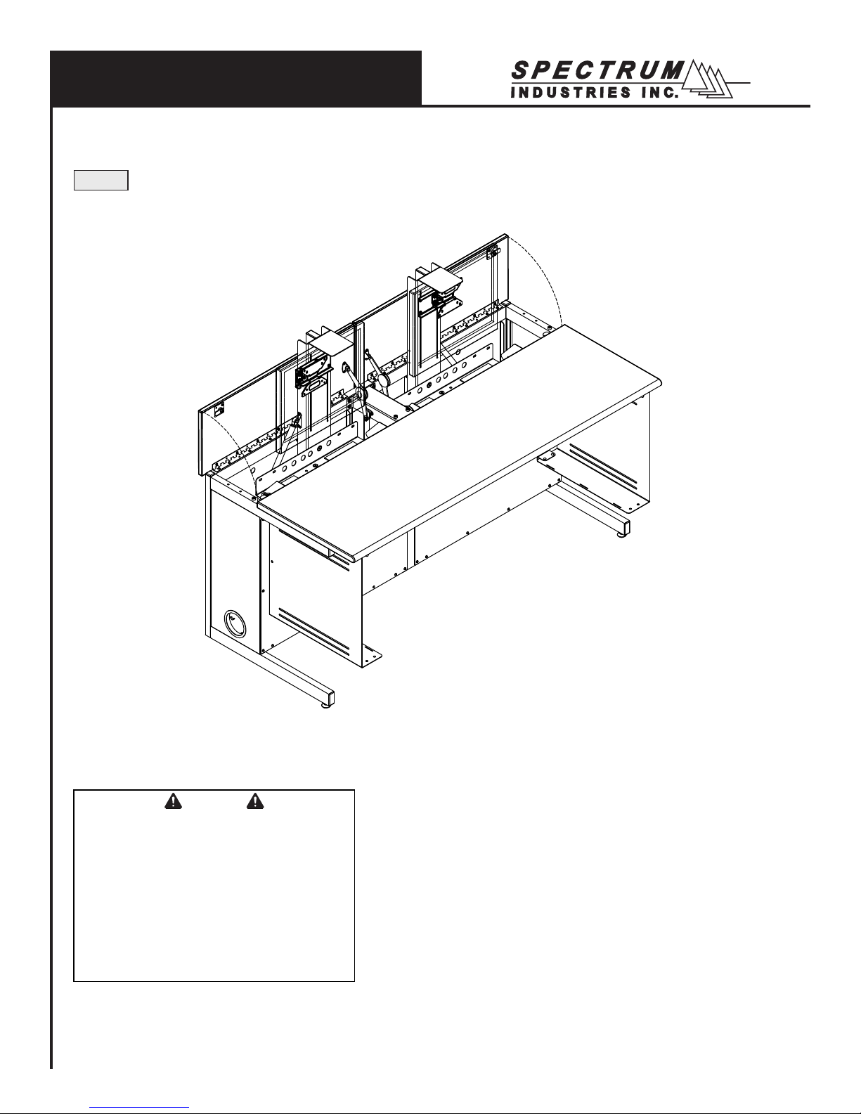
Owner’s Manual
60” Flex Insight Desk™ with offset VESA mounts
38979
Important
Before using this product:
• Read this manual
• Comply with all safety and operating instructions
• Ensure all parts and correct quantities are included
Any parts damaged during shipment must be reported
within 5 days of receipt. To report information regarding
missing parts or damage, to purchase parts or accessories, or if you have any questions, please contact us.
Thank you for purchasing Spectrum products!
Spectrum Industries, Inc
925 First Avenue, Chippewa Falls, WI 54729 USA
800 235 1262
715 723 6750
www.spectrumfurniture.com
0117128R5 Page 1 of 10
Page 2
Important Safety and Care Instructions
• Read this owner’s manual before assembly or operation.
• Do not allow children to move the table.
• For indoor use only. Do not install or store the table where it will be
exposed to moisture.
• Do not block the ventilation openings.
• Do not allow anyone to sit, stand, or climb on the table.
• Use a damp, soft-cloth, or sponge, with mild soap or detergent solution
to clean dirty surfaces. Do not use harsh solvents or abrasives.
• This table is intended for institutional use. It does not have any userserviceable parts or user-maintenance requirements. If servicing is
necessary, please contact Spectrum Industries for assistance.
Warning - Relocating audio and/or video equipment to furniture not speci cally
designed to support audio and/or video equipment may result in death or
serious injury due to the furnishing collapsing or over turning onto a child.
Warning - Death or serious injury may occur when children climb
on audio and/or video equipment furniture. A remote control or toys
placed on the furnishing may encourage a child to climb on the
furnishing and as a result the furnishing may tip over on to the child.
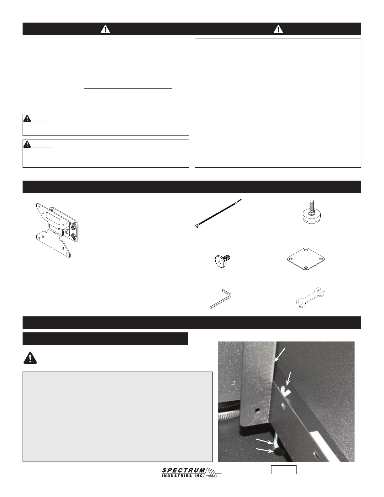
Hardware
Standard Swivel VESA Monitor
Mount with internal travel stops
provides 4-direction tilt, and works with
75mm and 100mm VESA monitor mounts
(includes mounting screws)
General Electrical Safety:
• Keep power switches in the OFF position before plugging or
unplugging from the wall outlet.
• Be sure total device / equipment load does not exceed 12-amps.
• Do not plug power cords into an extension cord.
• Inspect power cords for damage before each use. Do not use cords
that are damaged.
• Unplug power cord from electrical outlet by gripping the cord-do not
unplug by pulling only on the cord.
• Do not step on, drive over, drag, or place objects on power cords.
• For added safety, plug into a grounded outlet controlled by a GFI
(Ground Fault Interrupter) circuit breaker.
• Damaged electrical components can create signi cant hazards to
users and is not covered by the warranty. Repairs should always be
performed by a quali ed electrician.
• Electrical devices are not toys. Children are often unaware of the
hazards associated with electrical devices. This table must always
be used by adults or with adult supervision.
(15) 0102376
11” Zip ties
(4) 037779
5/16-18 x 1”
Glide
(2) 0107624
Assembly / Setup
1. Unlock monitor column
Note: Every Flex Insight Desk ships with one or two carriage bolts with wing nuts
locked in a keyhole slot under the bottom of the keyboard tray. These fasteners
prevent monitor column movement during shipping, and will need to be removed to
get the monitor column to function. A picture of the bolt and wing nut is shown here
from the back side of the desk. To remove, unscrew the wing nut by hand, and slip
the bolt out of the keyhole slot. The fasteners should be retained for reuse if you
will be transporting the desk.
If you transport the desk (in a trailer or truck) it is recommended to replace the
carriage bolt and wing nut. To replace, start the wing nut on the end of the bolt and
push the monitor column down into the lowered position. Wiggle the head of the
bolt into the slot from the large side of the keyhole. Let the monitor column rise
slightly to put tension on the wing nut. Tighten down until monitor column does not
move and is secure.
(4) 052605
1/4-20 x 15mm
JC bolts
(1) 025039
4mm Hex wrench
Carriage bolt
Keyhole slot
(1) 0107574
Unit-to-unit
bracket
(1) 025069
Glide wrench
Monitor column
Wing nut
Figure 1
0117128R5 Page 2 of 10
Page 3
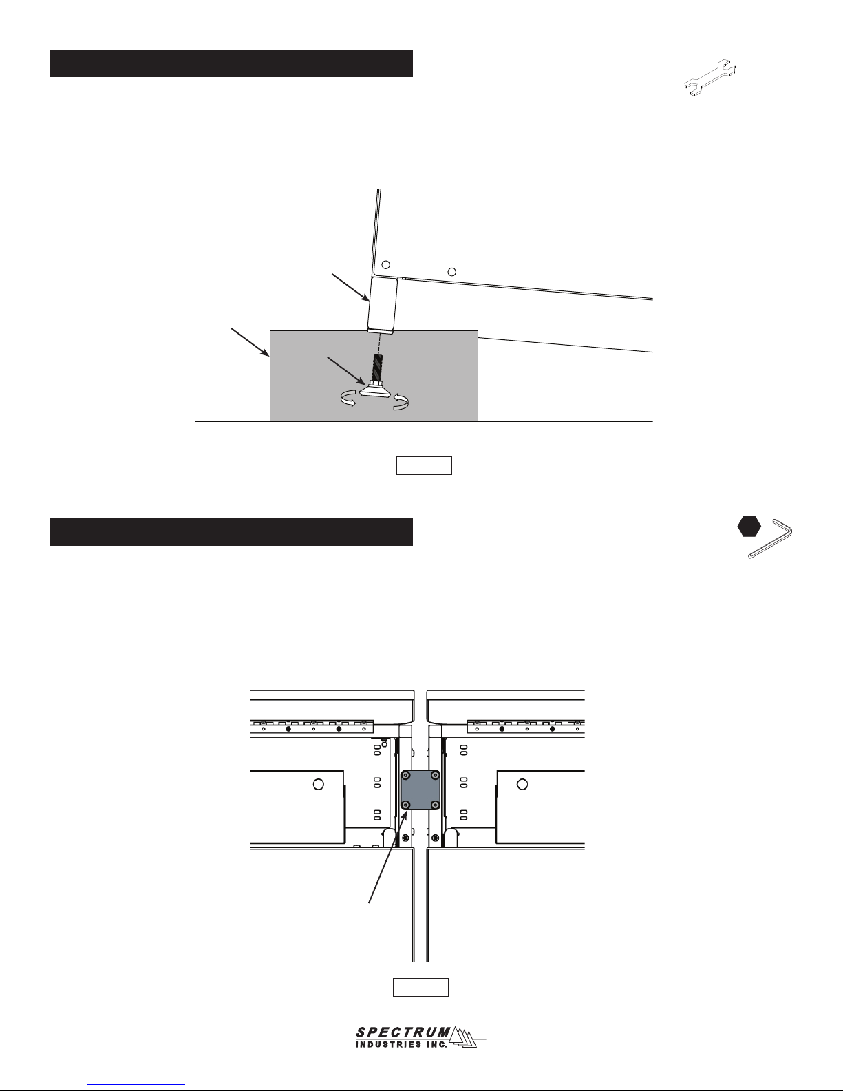
2. Install glides
1. Carefully lift one side of the desk and place a short wooden 4x4 or
2x4 block (or equivalent support) under the leg. This may require two
people. Figure 2.
2. Thread the two glides into the leg, tighten securely, and remove block.
3. Repeat this procedure on the other side of the desk.
4. The glides can be adjusted with the included glide wrench to level the
desk if necessary.
Leg
Wooden
block
Glide
Figure 2
Glide
wrench
3. Connecting desks together (optional)
1. Desks of equal height can be connected together with the included
unit-to-unit bracket. Figure 3.
2. Align desks next to each other in their nal location and raise monitor
compartment lids.
3. Attach desks together with a unit-to-unit bracket and (4) 1/4-20 x
15mm JC bolts. Tighten bolts securely.
4. Disconnect brackets to move/relocate desks.
Top view
Unit-to-unit
bracket
4mm
Figure 3
0117128R5 Page 3 of 10
Page 4

4. Monitor installation
3. The offset VESA bracket and mount are pre-installed but need not be
removed to install the monitor(s).
4. Attach the monitor to the VESA mount (buttery-shaped portion) with (4)
M4 x 12mm PHM screws. (Holes on top, slots on bottom). Figure 4.
Back of monitor
M4 x 12mm PHMS
(4 required)
Note: On most at panel monitors, it will be
necessary to remove the standard base that comes
with the monitor to use the VESA mounting option.
4mm
Figure 4.2
Offset VESA
bracket
VESA mount
(with holes on top,
slots on bottom)
5. CPU installation (Note-some desks may not include CPU slings)
1. Set the CPU unit into the CPU sling.
2. Make sure the CPU will be supported by both straps. Tighten the straps around the CPU
while keeping the buckles positioned as high as possible to avoid interference. Figure 5A.
Note: The center slot can be used for better support of smaller prole
CPU’s. If the center slot is necessary, take the rear strap out of the rear
slot and thread into the center slot shown in Figure 5A. Thread the
strap as shown in Figure 5B.
Figure 4.1
Install Tip: The friction dampener can
be disengaged from the lid to provide
additional clearance when installing the
monitor assembly. To disengage, release
the clip with a at screwdriver and push
the dampener arm off the pivot. The lid
can now be tilted away from the lift column.
Push the arm back onto the pivot after the
monitor has been installed. Figure 4.2
CPU
CPU sling
Center slot
Figure 5A
CPU
Strap / buckle
assembly
CPU sling
straps
Figure 5B
0117128R5 Page 4 of 10
Page 5

6. Cord management
1. With the back panel removed, connect the necessary monitor, keyboard, and mouse cords above the worksurface.
2. Position the keyboard as shown approximately 6” from the front edge of the worksurface with the mouse on the
opposite side of the CPU as shown. Figure 6A. This will provide enough slack in the cords during normal use and
provide for left and right mouse locations. With zip ties, secure cords to the back of the keyboard tray as shown.
3. The wire loom keeps monitor and keyboard cords together and routes them while the monitor is being raised and
lowered. Using a at head screwdriver, pry open each loom clip to release the wire loom. Figure 6B and 6C.
Zip tie cords here to
secure to keyboard tray
Flat panel
monitor
Top View
Zip tie monitor,
keyboard and
mouse cords here
Wire loom
and clip
Zip tie here to secure
CPU / Ethernet cords
to bottom of wiring tray
Figure 6B Figure 6C
Figure 6A
CPU location
0117128R5 Page 5 of 10
Page 6

4. With the loom removed, feed the monitor, keyboard, and mouse cords through the sliced opening of the loom to the bottom of
the desk as shown. Figure 6D.
5. Split the CPU wires out of loom approximately 3/4 of the way down the loom and plug into the CPU.
6. Reattach the loom with the clips while providing enough slack in the loom to allow the monitor column to fully extend and retract.
7. Secure the CPU cords to the bottom of the loom by attaching a zip tie around the loom directly above where the CPU cords exit
the loom. This will prevent the cords from backing out. Figure 6D.
8. Secure the CPU / Ethernet cords to the bottom of the wiring tray with a zip tie.
9. Use zip ties to secure additional cords as needed.
Back View
Flat panel monitor
Zip tie cords to
secure to desk
Zip tie monitor,
keyboard, and
mouse cords here
Loom clip
Monitor, keyboard
and mouse cords
to CPU
CPU
Wire loom
CPU cords exit loom here. Zip
tie around cords and loom to
prevent cords from backing out
Zip tie here to secure
CPU / Ethernet cords to
bottom of wiring tray
Loom clip
120VAC
Power cords
To wall outlet
Power strip
(not included)
Figure 6D
0117128R5 Page 6 of 10
Page 7

Operation
For classroom (worksurface) use:
1. Place the keyboard and mouse in the compartment tray under the monitor.
2. Lower the monitor by pushing down on the lift bracket until the
column is fully retracted, then close the monitor compartment lid.
Lockable desks can be locked at this point for security.
Monitor
compartment lid
For computer use:
1. Open the monitor compartment lid.
2. Raise the monitor by pulling up on the lift bracket until fully extended.
3. Take out the keyboard and mouse and set on the worksurface.
Lift bracket
Monitor
compartment lid
Figure 7.1 Figure 7.2
Caution: Do not assist or push the lid
closed when lowering the monitor or
lid hardware damage could result.
0117128R5 Page 7 of 10
Page 8

Instructor-side panel removal
4mm
Metal panel:
1. The panel is designed for easy removal using keyhole slots and
1/4-20 JC bolts. If the bolts are tight, slightly loosen with a 4mm
hex wrench. Figure 8.1.
2. Lift off the panel from instructor-side.
1/4-20
JC Bolts
Metal
panel
Laminate panel:
1. Open the monitor compartment lid.
2. Unscrew the 1/4-20 thumbscrews securing the panel. Figure 8.2.
3. Lift out the panel from instructor-side.
1/4-20
Thumbscrews
Laminate
panel
Figure 8.1 Figure 8.2
Maintenance
After approximately 300 cycles of opening and closing, the friction
dampener on the worksurface lid should be retightened to 13 in-lbs using
a torque wrench with a 4mm hex driver. If a torque wrench is unavailable,
tighten the friction damper with a 4mm hex wrench 1/8 turn at a time and
test. The correct adjustment is when the lid slows down between 2-4”
from closure. Figure 9.
4mm
Friction
dampener
4mm Hex
wrench
Figure 9
0117128R5 Page 8 of 10
Page 9

Accessories
Note: Slings and cover plates are available should it later be necessary to convert from
or to CPU towers. Single desks take one sling or cover plate, double desks take two.
CPU Sling for 24”D desks - 38981
• 4-8”W [10.2-20.3 cm] x 12”D [30.5 cm]
x 18”H [45.7 cm]
• 16 ga steel
• Includes nylon straps
• Shipping weight: 10 lb [4.5 kg]
CPU Sling for 30”D desks - 38980
• 4-8”W [10.2-20.3 cm] x 18”D [45.7 cm]
x 18”H [45.7 cm]
• 16 ga steel
• Includes nylon straps
• Shipping weight: 10 lb [4.5 kg]
1” Bell Glide Riser Kit - 98513
• Raises worksurface height to 30”
[76.2 cm]
• 5/16-18 thread
• Set of 4
• Shipping weight: .5 lb [.23 kg]
Cover Plate - 38978
• For use when CPU sling is not
needed or being used
• 16 ga steel
• Shipping weight: 1.25 lb [.57 kg]
7-Outlet Power Strip - 99024
• Electrical Rating: AC 125V, 15
Amps
• 1000 Joules surge capacity
• 12’ Cord length
• LED switch
• UL Listed
• Shipping weight: 1.9 lb [.86 kg]
EP8 Kits:
99011 - 72”
99010 - 60”
99018 - 48”
99009 - 44”
99008 - 36”
99014 - 30”
99013 - 24”
EP8 Kits and Accessories
Base Power Feed - 99022
with 36” exible cord
See spectrumfurniture.com for the latest
accessories and detailed warranty information.
0117128R5 Page 9 of 10
Page 10

Warranty
DESIGNED AND ASSEMBLED IN
CHIPPEWA FALLS
WISCONSIN.USA
We will make it right for you!
Spectrum is committed to provide complete customer satisfaction. Each of our products is manufactured from the best materials available and each
product is stringently monitored throughout the production process through our Quality Management System.
We expressly warrant that Spectrum products will be of good quality and workmanship and free from defect for the period set out in the warranty table below
from the date of delivery. This warranty shall not apply to defects or damage resulting from normal wear and tear, misuse, or unintended use, failure to follow
instructions related to the product’s installation or intended use, abuse, neglect, improper care, modifi cation or repair not authorized by Spectrum, or any other
cause outside the control of Spectrum. Spectrum will, at its sole option, either repair or replace the defective product.
This warranty is exclusive; no other warranty, written or oral, is expressed or implied. This warranty is given by Spectrum to Buyer or Buyer third party
end user and to no other person or legal entity. No Spectrum dealer, distributor, partner, reseller, agent or employee is authorized to make any modifi ca-
tion or addition to this warranty.
NOTWITHSTANDING ANYTHING TO THE CONTRARY, SPECTRUM WILL NOT UNDER ANY CIRCUMSTANCES BE LIABLE FOR INDIRECT OR LIQUIDATED DAMAGES, INCLUDING CONSEQUENTIAL, INCIDENTAL AND SPECIAL DAMAGES. IN NO EVENT SHALL SPECTRUM’S LIABILITY, WHETHER
UNDER CONTRACT OR WARRANTY, IN TORT OR OTHERWISE, EXCEED THE PURCHASE PRICE RECEIVED BY SPECTRUM FOR THE PRODUCT AT
ISSUE AND “RECALL ACTION” EXPENSES. SPECTRUM SHALL NOT BE SUBJECT TO ANY OTHER OBLIGATIONS OR LIABILITIES, WHETHER ARISING OUT OF BREACH OF CONTRACT, WARRANTY, TORT (INCLUDING NEGLIGENCE AND STRICT LIABILITY) OR OTHER THEORIES OF LAW, WITH
RESPECT TO PRODUCTS SOLD OR SERVICES RENDERED BY SPECTRUM, OR ANY UNDERTAKINGS, ACTS OR OMISSIONS RELATING THERETO.
Our Customer Service Department is ready to provide immediate attention to any questions, comments or concerns. They are available to answer your calls
Monday through Friday from 7 am to 5 pm CST. In addition your product comments or concerns are welcome via e-mail at: spectrum@spectrumfurniture.com.
Warranty Table
Item Warranty Period
Desk, table, cart and lectern chassis 10 Years
Electrical 2 Years
Flat panel monitor arms / gas spring / general parts 2 Years
Adjustable crank / electric legs and accessories 2 Years
Flat panel desk gas spring cylinders 2 Years
Height adjustable columns, lifts & accessories 2 Years
Casters & wheels 2 Years
Keyboard, mouse, trays 2 Years
Locks & keys 2 Years
Tubs, totes and other accessories 1 Year
Chairs
Structural components, including gas cylinders,
wood, metal and plastic parts (i.e., chair frames,
bases and control handles)
Consumable items (i.e., casters, glides, etc.) 5 Years
In-stock upholstery 5 Years
Customer supplied material No Warranty
7 Years
925 FIRST AVENUE, CHIPPEWA FALLS, WI 54729 / 800-235-1262 / 715-723-6750 / WWW.SPECTRUMFURNITURE.COM
© 2019 Spectrum Industries Inc., All rights reserved.
0117128R5 Page 10 of 10
 Loading...