

Page 1
Assembly Instructions
Assembly Instructions
Important
Before you begin, read and comply with all safety and operating instructions,
and ensure all parts and correct quantities are included.
Any parts damaged during shipment must be reported within 5 days of receipt.
To report information regarding missing parts or damage, to purchase parts
or accessories, or if you have any questions, please contact us.
www.spectrumfurniture.com
800-235-1262, 715-723-6750
Thank you for purchasing Spectrum products!
(1) Mobile device module
55506-H0 - no power
55506-HA - w/ AC power strip (12 outlets)
55506-HC - w/ (2) 6-port USB chargers
(2) 0142528
Bar support
(with threaded
weld studs)
(2) 0145039
Bar support
B-side
(with slots)
(4) 056284
8-32 Wing nut
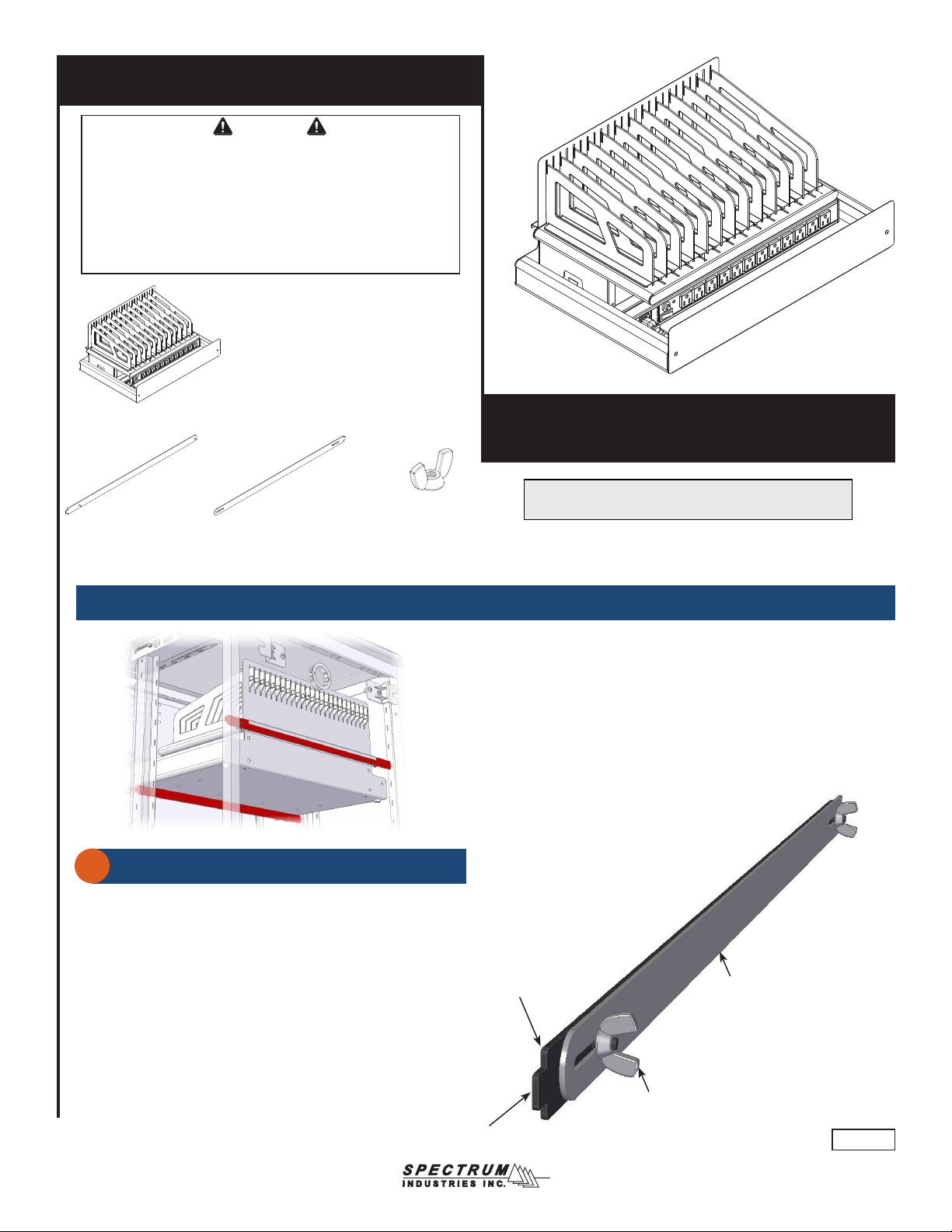
Mobile Device Module
55506
The Device Charging Module can store and charge up to
12 devices (most Chromebooks, tablets, or notebooks).
Installing module into cart or Techcenter
Assembled bars
1
1. The bars should be assembled with the tabs facing away from each
other as shown in Figure 1.
2. Loosen the (2) wing nuts slightly.
3. Repeat for the 2nd set of bars.
Bar support
(with threaded weld studs)
(skip to p.3 for stand-alone module)
Tab
Bar support B-side
(with slots)
X 2
Tab
8-32 Wing nut
(2 per assembly)
Figure 1
0191401R2 Page 1 of 4
Page 2
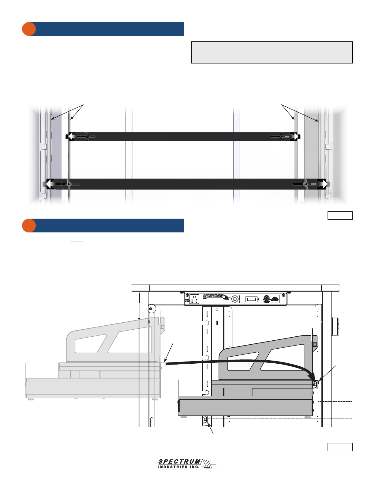
Installing bars
2
1. Determine the approximate location (height) you would like the
module to be mounted. The rear bar is (2) slots higher than the front.
2. Insert one tab into a slot in the left slotted upright. Figure 2.
3. Insert the opposite tab into the corresponding right slotted upright
and fully extend the bar assembly into place.
4. Lock the extended position of the bars by securely tightening the (2)
wingnuts. Be sure both wingnuts are tight.
5. Repeat for the 2nd set of bars.
Left slotted
uprights
Rear bar Assembly
Front bar Assembly
Note: When determining the location of the module, be sure the module
will clear any obstructions that may be inside the cabinet and enough
clearance (height) is provided for all module devices.
Right slotted
uprights
Figure 2
Installing module
3
1. Carefully set the empty module onto both sets of bars. Be sure the
rear channel “hooks” the rear set of bars fully. Figure 3.
Rear
channel
Bars
Bars
Device Module
Figure 3
0191401R2 Page 2 of 4
Page 3

Installing devices
1. Place devices into bays with the charge plug accessible on top or front.
Figure 4.
2. With power cord unplugged and power switched OFF, plug chargers
into outlets.
3. Place chargers and excess cords behind power strip under devices.
CAUTION
While the rubber feet on the bottom of the module prevent scratching
of surfaces the module is placed on, screw heads protruding under the
unit can still possibly scratch these surfaces in some circumstances.
Place the module on a level surface using all 4 rubber feet. Do not
drag or slide the module across tables or worksurfaces. Use caution
when moving. Always remove all devices to reduce weight, and unplug
power strip prior to moving.
Dividers
Dividers can be easily recongured for different devices if needed.
Removal:
1. Press and hold the locking tab and slide the divider forward.
2. Lift divider out of slot. Figure 5.
Device
X 12
Figure 4
Installation:
1. Insert divider into slot.
2. Slide back and ‘click’ into place.
2
1
Locking
tab
Figure 5
0191401R2 Page 3 of 4
Page 4
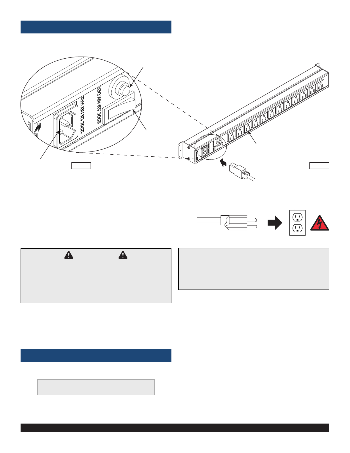
Power Strip (if equipped)
Reset button
Power switch
12-outlets
IEC Inlet for
8’ power cord
CAUTION
Keep power switched OFF when plugging in power cord to wall outlet or
device chargers into the power strip.
The user should be aware of the amp draw of the devices used with this
module-especially when maxing out the storage and charging capacity.
Exceeding 15 amps will trip the circuit breaker. Please consult the owners
manual of your specic device for power consumption information.
Figure 6.1Figure 6.2
8’ nominal [244 cm] 14 AWG,
3-wire IEC power cord
(to wall outlet)
Electrical Specs
• 12-outlets, .83A max each
• 125VAC, 12A max, 60Hz
• 15-amp breaker
• IEC quick-release (replaceable) 8’ nominal, 14 AWG, 3-wire power cord
• ETL recognized (certied to 60950-1)
USB chargers (if equipped)
Note: If USB chargers are included, install them inside
the tray (under the dividers) and connect to power.
925 FIRST AVENUE, CHIPPEWA FALLS, WI 54729 / 800-235-1262 / 715-723-6750 / WWW.SPECTRUMFURNITURE.COM
© 2019 Spectrum Industries Inc., All rights reserved.
0191401R2 Page 4 of 4
 Loading...