

Page 1
Assembly Instructions
Important
Before you begin, read and comply with all safety and operating instructions,
and ensure all parts and correct quantities are included.
Any parts damaged during shipment must be reported within 5 days of receipt. To
report information regarding missing parts or damage, to purchase parts or accessories, or if you have any questions, please contact us.
www.spectrumfurniture.com
800-235-1262, 715-723-6750
Thank you for purchasing Spectrum products!
(1) 0118160
Keyboard
Tray
(1) 050092
12” Slide set
(6) 0100167
8-32 x 1/2” PH
thread-cutting
screw
(8) 037542
#8 x 5/8” PHSM
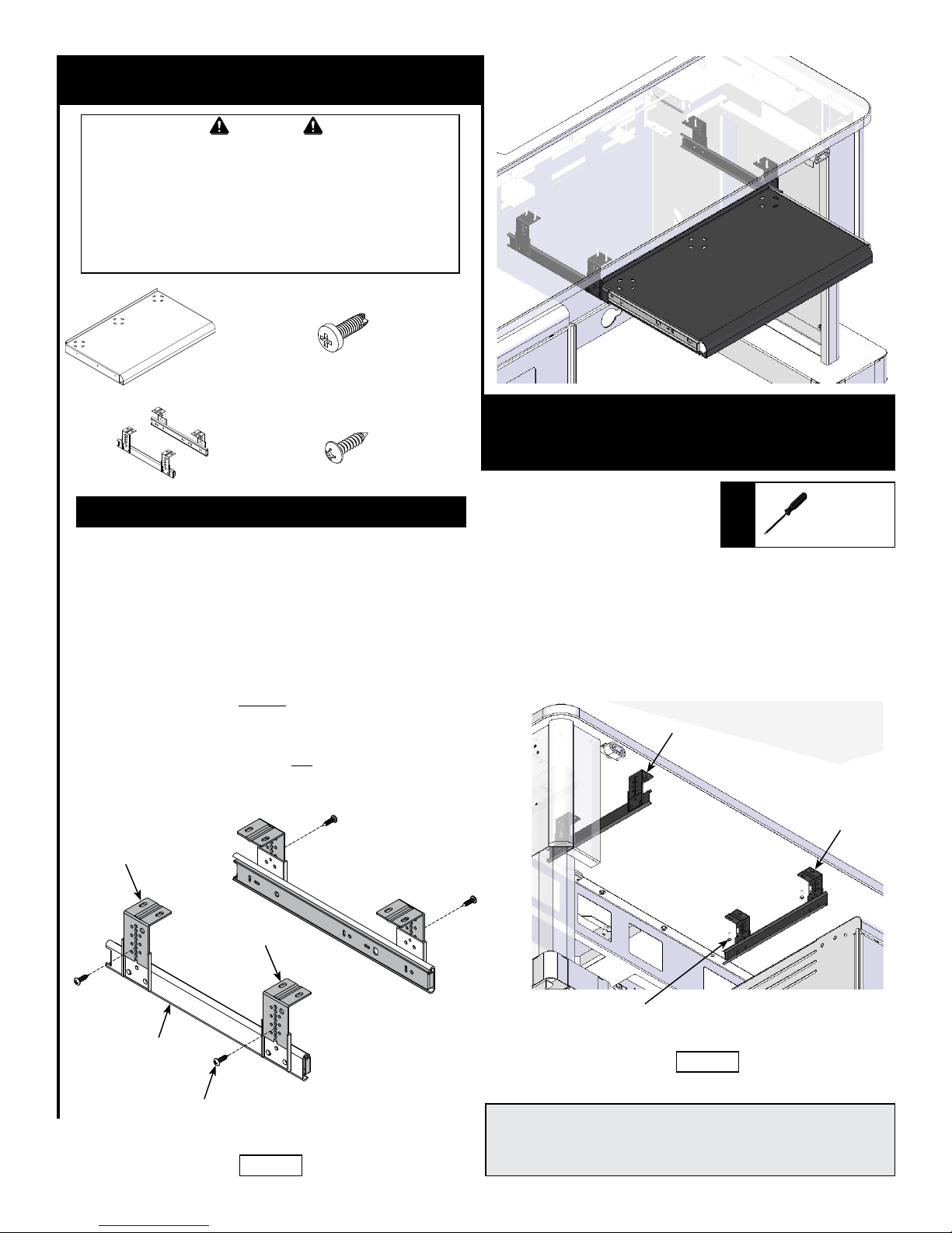
1. Assemble Slide Brackets
1. Attach the ‘L’ brackets to each outer slide with screws (included
with slides). The brackets need to be attached “inboard” (facing
each other). Figure 1A. Multiple height positions / mounting
holes are available with the brackets-use the same hole position
on all 4 brackets.
2. Tighten the bracket screws securely.
3. Separate the inner from the outer slides using the black levers.
4. Raise the lectern up all the way and unplug the power cord.
5. Determine which side of the lectern you want the keyboard tray
installed (left or right-side). The tray should be installed under the
worksurface on the side opposite the rack cabinet using the predrilled worksurface holes.
6. Attach each outer slide (‘L’ brackets) to the worksurface using
(4) #8 x 5/8” PHSM screws and pre-drilled worksurface holes.
Tighten the screws completely on one slide only-leave the screws
other slide slightly loose. Figure 1B.
Keyboard Tray for Freedom XRS Elite
55334
Phillips
Screwdriver
Outer slide
Tools
Required
™
‘L’ Bracket
‘L’ Bracket
Outer slide
Screw
(included with slides)
Figure 1A
Outer slide
XRS Elite
worksurface
#8 x 5/8” PHSM
(4 per slide)
Figure 1B
Note: The keyboard tray may protrude up to a maximum of 3.9” [10 cm]
below the worksurface. If the lectern is used for ADA use, a higher adjusted worksurface will be necessary to provide ADA leg clearance. The
‘L’ brackets can also be adjusted to provide varied keyboard heights.
0118905R1 Page 1 of 2
Page 2
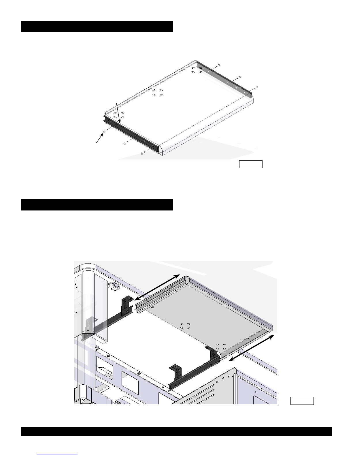
2. Attach Inner Slides to Tray
1. Attach each inner left and right slide to the keyboard tray with (3)
8-32 x 1/2” PH thread-cutting screws and tighten securely. Figure 2.
Inner
slide
8-32 x 1/2” PH
thread-cutting screw
(3 required per slide)
Keyboard Tray
Figure 2
3. Install Keyboard Tray
1. Align the tray assembly with the installed slides and slide together.
Figure 3.
2. Open and close (cycle) the tray a few times to ensure parallel and
free movement.
3. With the keyboard tray pulled out, securely tighten the (3) loose
worksurface slide screws from step 1.
Keyboard Tray
Assembly
925 FIRST AVENUE, CHIPPEWA FALLS, WI 54729 / 800-235-1262 / 715-723-6750 / WWW.SPECTRUMFURNITURE.COM
© 2016 Spectrum Industries Inc., All rights reserved.
Figure 3
0118905R1 Page 2 of 2
 Loading...