

Page 1
66455001
Rev 01
Vivint
ZWave® Plus
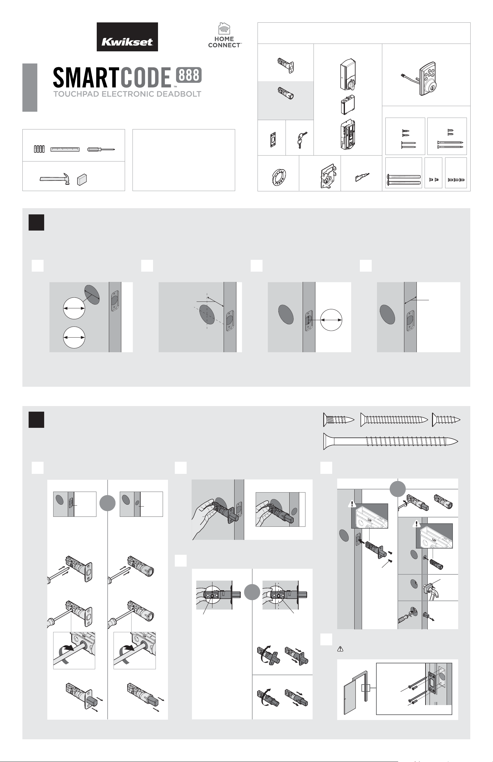
Parts in the box
Latch
A
Interior Assembly
M
Exterior Assembly
Keys
B
K
L
ENGLISH
“B” is n ot included. If n eeded,
Installation and User Guide
please c ontact Kwikset to o rder
a drive-in l atch for your lock.
Strike
Required tools
C
E
Kwi kse t
Ruler4 AA Batt eries
Additional Tools (depending on application)
Phillips head screwdriver
Technical Support
1-866-863-6584
Adapter
Ring
Mounting
Plate
SmartKey
Too l
www.kwikset.com
Hammer Wood block
Prepare the door and check dimensions
1
D
If drilling a new door, use the supplied template and the complete
door drilling instructions available at www.kwikset.com/doorprep.
Measure to conirm that the hole in
A B C D
the door is either 21/8" (54 mm) or
11/2" (38 mm).
Measure to conirm that the backset is
either 23/8" or 23/4" (60 or 70 mm).
Measure to conirm that the hole in
the door edge is 1" (25 mm).
G
F
Fasteners
03809 46780
N
P
66128 64109
T
S
49191
U
H
Measure to conirm that the door is
between 13/8" and 2" (35 mm and
51 mm) thick.
Q
V
backset
1"
25 mm
actual
size
21/8"
54 mm
or
11/2"
38 mm
Note: Additional door preparation may be
required for doors with 11/2" (38 mm) holes.
Consult the deadbolt drilling instructions at
www.kwikset.com/doorprep.
Install the latch and strike
2
23/8" or 23/4"
60 or 70 mm
NPSQ
Is the door edge chiseled? Which latch are you installing?
A D
YES NO
Hold the latch in front of the door hole, with the latch
B
face lush against the door edge.
Latch “A” Latch “B”
13/8" – 2"
35 – 51 mm
or
chiseled
Use latch “A”. If the
latch bolt is not already
extended, extend the
latch bolt as shown.
A
or
Use latch “B” (not
included). If the latch
bolt is not already
extended, extend the
latch bolt as shown.
not
chiseled
B
A
Is the D-shaped hole centered in the door hole?
C
YES NO
or
D-shaped hole D-shaped hole
No adjustment is required.
Proceed to next step.
Rotate latch face as
shown to extend latch.
A
B
B
B
A
N or P
wood
block
C
Install strike on the door frame.
E
Make sure the hole in the door frame is drilled a
minimum of 1" (25 mm) deep.
(2x)
Longer screws
install closest to
the door jamb.
S (2x)
1 / 4
Q (2x)
door frame
Page 2

Install the exterior keypad
3
actual
size
T
What is the diameter of the hole in the door?
A
Diameter is 21/8"
(54 mm)
or
21/8"
54 mm
“D” is required for installation .
Install “D” on “F”.
F
D
Locate screws for step 3C and keep them within reach.
B
T
“D” is not needed for
installation. Discard “D”.
Diameter is 11/2"
(38 mm)
11/2"
38 mm
D
Install exterior keypad and mounting plate.
C
a
Cable goes
underneath latch.
c
Keep parallel to
edge of door.
Tighten
screws evenly.
T (2x)
b
Support exterior
assembly during
mounting plate
installation.
G
F
Route cable through
center hole, then push
cable into b ottom hole.
d
E
Insert key and
test latch. If latch
does not extend or
T
retract smoothly,
adjust screws (T).
Remove key when
inished and make
sure the latch bolt
is fully extended.
Install the interior assembly
4
Remove battery cover and battery pack from interior assembly.
A
a
Make sure turnpiece is in
the vertical position.
c
Make sure
turnpiece shaft is
rotated as shown.
L
actual
size
U
Install interior assembly onto mounting plate.
B
b
a
L
align
b
L
M
d
K
Do not install
batteries
until step 5.
Ensure tight cable
connection.
c
L
Lay excess cable lat inside the
bottom of the interior housing.
d
U
(2x)
bottom
hole
Install the batteries and perform the door handing process
5
This step will teach your lock the orientation of your door and is crucial to lock operation.
Install 4 AA batteries in battery pack.
A
Make sure the door is open, and
B C
insert the battery pack.
K
Ensure correct polarity.
For best results, use
new, non-rechargeable
Alkaline batteries only.
After a few seconds, the latch bolt will retract and extend on
its own to learn the orientation of the door. This is called the
door handing process, and it is crucial to lock operation.
Status LED will indicate
success or failure.
Success: LED lashes green
Fail ure : LED remains solid red
If the latch bolt does not move on its own, or if the Status LED indicates
D
a door handing failure, make sure the cables are connected, the
batteries are installed correctly, and attempt this procedure again.
If the door handing process is still unsuccessful after a second
attempt, perform the “Manual Door Handing” procedure on page 4.
Note: Latch
bolt will only
retract half way.
2 / 4
Page 3

Add the lock to your smart home system
6
Initiate the process to add
A B C
the lock to your system at
your smart home controller.
Refer to your smart home
system instructions for
more information.
When prompted by your smart home system to add the
lock, press button “A” on the lock interior one time. The
red LED will illuminate when the lock enters Add Mode.
button “A”
Please allow time for the controller to add the lock.
Add user codes (30 max)
7
It is recommended that you add and
delete all user codes through your smart
home control system. If your system
does not allow this, codes may be added
directly to the lock as shown here.
Programming Timeout
During programming, if no button is
pressed for ive seconds, the system will
time out (indicated by three beeps and
a red lashing lock button), and you will
need to restart the procedure.
Make sure the door is open. Press
A
the Program button once.
Enter user code. A total of 30 user
B C
codes may be programmed.
If successful, re-name the lock in your system (if applicable).
If unsuccessful, follow your system's instructions to remove
D
the lock from the controller and any other network, then press
button “A” on the lock one time.
Perform steps 6A6C again.
If still unsuccessful, consult the Programming
and Troubleshooting Guide on the
SmartCode 888 page at kwikset.com.
Press Lock button once.
Each user code
must be a unique
code between
4 and 8 digits,
depending on
your smart
home system.
What lights and sounds does the lock produce?
D
Mastercode
For enhanced security, a
mastercode may be used
when adding and deleting user
codes. For more information
about the mastercode,
download the Programming
and Troubleshooting Guide
on the SmartCode 888
page at kwikset.com.
Test the lock (review normal operation) and re-key the lock (if needed)
8
Conirm that the code(s) added in previous step can unlock the door.
Locking the Door Unlocking the Door Re-Key with SmartKey
Lock button lashes green once with one beep Lock button lashes three times with three beeps
or
green
1x
Programming was succe ssful. Programming was unsuccessful.
Make sure not to pause for more than 5 seconds during programming .
Make sure the user code is not a duplicate and that it is between 4 and 8 digits
duri ng your next a ttemp t. Make sure the lock has room fo r an additional cod e.
If all use r code positions are illed, d elete a code to make room for t his one.
red
3x
Press Lock
button once.
Install the interior cover
9
Install the interior cover. Secure the interior cover with three (3) screws. Note: To access the battery pack or back panel,
A B
Enter user co de.
Re-key the lock
to work with your
existing key. See
the supplied
SmartKey Re-key
instructions for
more information.
slide up the window on the interior cover.
H
actual
size
V
M
V (3x)
3 / 4
Page 4

Reference Guide
SmartCode 888 at a Glance
Interior (cover removed)
Exterior
Keypad
Lock
button
Keyway
SmartKey
tool hole
Note: When the cover is
removed, the turnpiece shaft
can be used to manually
lock and unlock the do or.
Tr ou bl es h oo ti n g
A complete Programming and Troubleshooting Guide is
available on the SmartCode 88 8 page at www.kwikset .com.
Status LED
The Status LED blinks every 6
seconds to communicate whether
the door is locked or unlocked.
This feature is on by default.
Blinking Green: Unlocked
Blinking Amber: Locked
Blinking Red: Low battery
Solid Red: Unsuccessful door handing
process . See online Programming
and Troubleshooting Guide.
Turn Status LED On/O
1. Press Program button once. 2. Press button “A” once.
Status
LED
Back
panel
Button “A”
Program
button
Status
LED
Tur np ie ce
shaft
System Alerts
Alert Reason Solution
Lock button lashes
red once with one
beep*.
Lock button lashes
red three times with
three beeps*.
Lock button lashes
red 15 times with 15
beeps*
Lock button lashes
red with fast beeping
sound for three to four
seconds.
Lock button lashes
green with continuous
beeping sound for two
seconds.
One incorrect code
entered.
No user code
programmed.
Programming timeout
after ive seconds.
Unsuccessful
programming.
Three incorrect codes
entered within one
minute.
Low battery. Replace batteries.
Door jammed while
attempting to lock.
Re-enter code.
Program at least one
user code.
Attempt programming
procedure again.
Re-enter code after
60 second keypad
lockout.
Manually re-lock door.
If needed, reposition
strike.
Deleting a single user code
Note: All codes may be deleted at once if the mastercode
is enabled. For more information about the mastercode,
consult the Programming and Troubleshooting Guide.
If no but ton is presse d for ive second s, the system wi ll time
out, an d you will need to re start the proce dure.
1. Press Program button once. 2. Press Lock button once.
3. Enter use r code to be deleted. 4. Press Lock button once.
5. Re-enter user code. 6. Press Lock button once.
If unsuccessful: Make sure to en ter the same vali d code in steps 3 and 5 .
Tes t co de: W hile the door is op en, test the use r code
to make sure it n o longer unloc ks the door.
Auto-Lock
Auto-lock automatically re-locks the door after unlocking. This feature is set to 30 seconds and is turned o by default.
Turn Auto-Lock On/O Change Auto -Lock Time Delay
1. Press Program button once. 2. Press button “A” once. 1. Press Program button once. 2. Press button “A” once.
3. Pre ss button “ 34” multiple
times if ne eded to reach
desired state.
Green Loc k Button:
Feature is en abled.
Red Lock Bu tton:
Feature is di sabled.
4. Press Lock button once. 3. Press button
“9 0” once.
4. Press button once
that corresponds
to desired
time delay:
“12” – 30 sec.
“34” – 60 sec.
“5 6” – 90 sec.
“78” – 120 sec.
“9 0” – 180 sec.
5. Press Lock
button once.
3. Pre ss button “ 12” multiple
times if ne eded to reach
desired state.
Green Loc k Button:
Feature is en abled.
Red Lock Bu tton:
Feature is di sabled.
4. Press Lock button once.
Manual Door Handing
If needed, the door handing process can b e initiated manually.
This is useful if the lock is being moved to a di erent door.
1. Remove battery pack.
3. Press the
Program
button once
more.
4. The latch bolt will extend
and retract to learn the
orientation of the door.
The Status LED will indicate
success or failure.
2. Press and HOLD the Program
button while reinser ting the
battery pack.
Release button once battery
pack is installed. The status
LED will lash red and green.
Mute/Unmute Audio
Audio is on by default.
1. Press Program button once. 2. Press but ton “A” once.
Factory Reset
A factory re set will delete all codes associate d with the lock, and it will
remove it from your smart home system.
1. Remove battery pack.
Status
LED
Success: LED lashes green
Fail ure : LED remains solid red
If the Status LED indicate s a failure,
see the online Programming
and Troubleshooting Guide
or call Technical Support.
3. Pre ss the Program button
3. Pre ss button “ 56” multiple times if
once more. When the LED
lashe s green and you hear
one beep, the lock has been
reset.
needed to reach desire d state.
Green Loc k Button:
Feature is en abled.
Red Lock Bu tton:
Feature is di sabled.
2. Press and HOLD the Program
button while reinser ting the
battery pack.
Keep holding the button
for 30 seconds until
the lock beeps and the
status LED lashes red.
4. After a few seconds, the lock will initiate the door
handing process, and the latch bolt will extend
and retract to learn the orientation of the door.
4. Press Lock button once.
Status
LED
Network Information
Removing the lock from the network
Follow your smart home system’s instructions
to remove the lock from the network. When
prompted by the system, press button A” on
the lock inte rior once.
ZWave System Notes
This product is a security enabled Z-wave Plus product and must be used with a Se curity
Enabled ZWave controller to be fully utilized. ZWave is a “Wireless mesh network,” and
results may vary based on building construction and communication path.
To assure interoperability, each ZWave product must pass a stringent conformance test to
assure that it meets the ZWave stan dard for complete compliance with all other devices and
controls. The ZWave identity mark assures consumers , integrators, dealers and manufacturers
that their products will reliably perform with any other ZWave device. And, regardless of the
vendor, always powered nodes may act as a repeater for Kwikset/Weiser/Baldwin products.
ZWave Coniguration and Association Parameters are available on
the SmartCode 88 8 page at www.kwikset .com.
Important Safeguards
1. Read all instructions in their entirety.
2. Familiarize yourself with all warning and caution statements.
3. Remind all family members of safety precautions.
4. Protect your user codes and mastercode.
5. Dispose of used batteries according to local laws and regulations.
CAUTION: Prevent unauthorized entry. Since anyone with access to the back panel can
change the user codes, you must restrict access to the back panel and routinely check the
user codes to ensure they have not been altered without your knowledge. The use of a
mastercode can help protect your system’s settings.
WARNING: This Manufacturer advises that no lock can provide complete security by itself.
This lock may be defeated by forcible or technical means, or evaded by entry elsewhere
on the property. No lock can substitute for caution, awareness of your environment, and
common sense. Builder’s hardware is available in multiple performance grades to suit the
application. In order to enhance security and reduce risk, you should consult a qualiied
locksmith or other security professional.
4 / 4
© 2016 Spectrum Brands, Inc.
 Loading...