

Page 1
Assembly Instructions
Important
Before you begin, read and comply with all safety and operating instructions,
and ensure all parts and correct quantities are included.
Any parts damaged during shipment must be reported within 5 days of receipt. To
report information regarding missing parts or damage, to purchase parts or accessories, or if you have any questions, please contact us.
www.spectrumfurniture.com
800-235-1262, 715-723-6750
Thank you for purchasing Spectrum products!
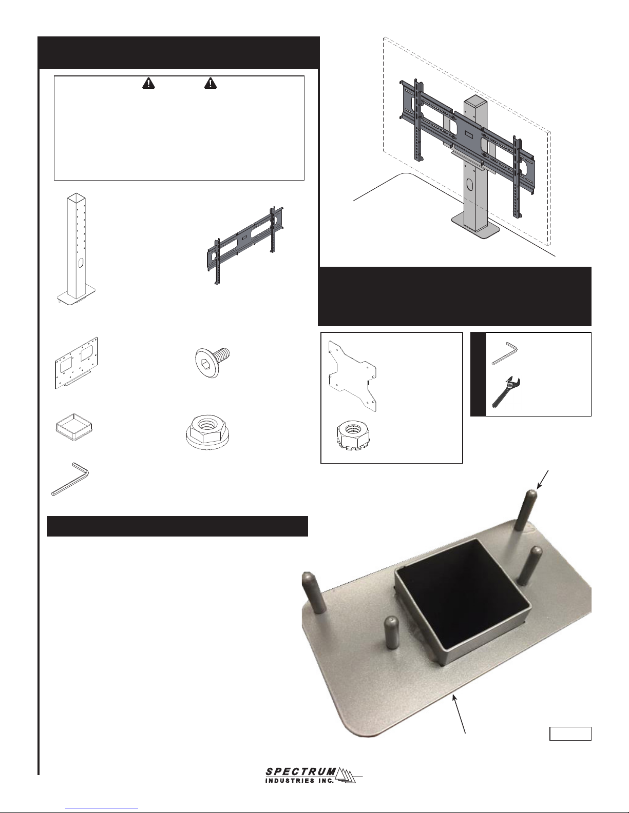
(1) 0118510
Upright assembly
(1) 0131924
Upright bracket
(1) 0118193
End cap 3” x 3”
(1) 025039
4mm Hex wrench
(1) 0119747
Monitor mount
(12) 052605
1/4-20 x 15mm
JC bolt
(4) 0108896
1/4-20 Flanged
serrated locknut
Installation
1. With the upright assembly upside-down, remove the rubber
thread protector from each threaded stud. Figure 1.
(A utility knife may be needed to cut off.)
Display Stand
37130
(1) 0139729
200mm VESA
adapter plate
(4) 0106543
1/4-20 Keps nuts
Tools Required
4mm Hex wrench
(included)
7/16” or Adjustable
wrench
Rubber thread
protectors
Bottom of upright
assembly
0118583R4 Page 1 of 4
Figure 1
Page 2
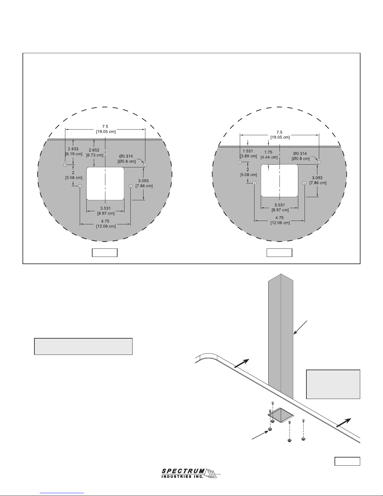
2. Be sure the worksurface being used has the cutout / hole pattern
shown in Figure 2.1, or Figure 2.2.
Mounting holes and cutout needed
(on at end of worksurface)
InVision / Element / Nano Tables
Figure 2.1
Optio Tables
Figure 2.2
3. An unattached worksurface will facilitate installation of the display
stand fasteners. If attached, remove the worksurface fasteners
securing it to the base and slide the worksurface 6” over the base to
provide access to the display stand mounting holes. Figure 3.
4. Align the studs and insert the upright into the worksurface mounting holes.
5. With a second person holding the upright, Install (4) 1/4-20 Flanged
serrated locknuts and tighten securely.
Note: For InVision Nano table installation,
see p.3 for special instructions.
Worksurface
1/4-20 Flanged
serrated locknut
(4 required)
Upright
assembly
Pull worksurface out
about 6” to access
display stand mounting
holes
Figure 3
0118583R4 Page 2 of 4
Page 3

6. Attach the upright bracket to the upright assembly as shown using
(4) 1/4-20 x 15mm JC bolts and tighten securely. (Multiple mounting
holes / height positions are available on the upright assembly).
Figure 4.
Upright bracket
1/4-20 x 15mm JC
bolts (4 required)
Upright
assembly
Figure 4
7. Refer to the instructions included with the monitor mount for
complete monitor installation procedure.
8. Install the monitor mounting plate to the upright bracket with
(4) 1/4-20 x 15mm JC bolts and tighten securely. Figure 5.
9. Install monitor and route wiring through the upright opening.
10. Install end cap on top of upright.
Note: The assembled Display Stand
accommodates most 37”-70” monitors
up to 125 lb.
WARNING
The monitor should always be lifted
off the stand before moving the table.
End cap
Monitor
mounting plate
1/4-20 x 15mm JC bolts
(4 required)
Upright opening
Figure 5
0118583R4 Page 3 of 4
Page 4

200mm VESA adapter plate (optional)
Note: The included adapter plate is for 200mm VESA monitor
applications. To install, align the adapter plate posts with the
hanging rail mounts and secure with 1/4-20 Keps nuts.
Hanging rail
200mm VESA
adapter plate
Attach 200mm VESA
monitor using these
(4) holes
(4) 1/4-20 Keps
nuts to secure
InVision Nano Table Installation only
Note: To install the Display Stand on a Nano table,
the end panel must be removed prior to installing.
1. Remove the (4) screws shown. Figure 7.1.
2. Remove end panel.
Remove these
screws
Figure 6
3. Align the studs and insert the upright into the worksurface
mounting holes.
4. With a second person holding the upright, install the (2) inner
1/4-20 Flanged serrated locknuts. Figure 7.2.
5. Replace the end panel.
6. Install the (2) outer 1/4-20 anged serrated locknuts.
7. Tighten all locknuts securely.
Upright assembly
1/4-20 Flanged
serrated locknut
(4 required)
End panel
Remove these screws
925 FIRST AVENUE, CHIPPEWA FALLS, WI 54729 / 800-235-1262 / 715-723-6750 / WWW.SPECTRUMFURNITURE.COM
Figure 7.1
Figure 7.2
0118583R4 Page 4 of 4
 Loading...