

Page 1
2011 Emission Certified
LPG Fuel System
3.0L GM Engine
Parts & Service Manual
Including Labor Time Guide
Revision A/March, 2011
Page 2

2011 Emission Certified
LPG Fuel System
3.0L GM Engine for
Parts & Service Manual
Table of Contents
General Information ................................................................................................ 5
An overview of this Service Manual
Maintenance ............................................................................................................ 9
General maintenance and maintenance interval information
Fuel System ........................................................................................................... 17
An overview of the LPG fuel system and its components
LPG Fuel System Diagnosis ................................................................................ 27
How to identify a general problem
LPG Symptom Diagnostics .................................................................................. 35
How to correct a specific problem
Electrical Section .................................................................................................. 51
Diagnostic Scan Tool ...................................................................................... 53
Using the DST for testing and trouble shooting
Page 3

Wire Schematic ................................................................................................... 81
Engine wiring schematics
Engine Wire Harness Repair ............................................................................. 85
Repairing a wire harness on the vehicle
Diagnostic Trouble Codes (DTCs) .................................................................... 89
Application, schematic and DTC specific code information
Servicing the Fuel System .................................................................................... 237
Step by step instructions on how repair and/or replace fuel related Components
LPG Parts Diagram ................................................................................................ 255
Illustrations and part views
Labor Time Guide .................................................................................................. 299
The labor reimbursed by IMPCO for warrantable service and repairs
Definitions .............................................................................................................. 317
Definitions of phrases and acronyms used throughout this Service Manual
Appendix ................................................................................................................ 323
Supplemental charts and tables
Page 4

4
Page 5

General Information
5
Page 6
INTRODUCTION
This service manual supplement has been developed to provide the service technician with the
basic understanding of the IMPCO certified fuel
and emission systems for the 3.0L GM engine.
This manual should be used in conjunction with
the base engine manual and the OEM service
manual when diagnosing fuel or electrical problems.
HOW TO IDENTIFY THE ENGINE YEAR
The emission label on the engine will identify the
specific model year.
SERVICING YOUR EMISSIONS
CERTIFIED ENGINE
Any maintenance and repair should be performed
by trained and experienced service technicians.
Proper tools and equipment should be used to
prevent injury to the servicing technician and
damage to the vehicle or components. Service
repairs should always be performed in a safe environment and the technician should always wear
protective clothing to prevent injury.
For parts or labor to be reimbursed under the
IMPCO Technologies Inc. emission warranty, only
work performed by IMPCO or OEM trained technicians using only IMPCO specified parts will qualify
for reimbursement. Refer to the IMPCO Labor
Time Guide for additional information.
For parts or labor not reimbursed under warranty,
a repair shop or person of the owner’s choosing
may maintain, replace, or repair emission-control
devices and systems. It is highly recommended
that any replacement parts used for maintenance
or for the repair of emission control systems be
new OEM replacement parts. The use of other
than genuine IMPCO replacement parts may impair the effectiveness of emission control systems,
therefore, the owner should assure that such parts
are warranted by their manufacturer to be equivalent to genuine IMPCO OEM parts in performance
and durability.
Fuel other than HD-5 or HD-10 may cause harm
to the engine’s emission control system and a
warranty claim may be denied on this basis if operators can readily find the proper fuel.* Use of
any other fuel may result in your engine no longer
operating in compliance with CARB or EPA emissions requirements.
*Not Applicable in the state of California.
FUEL LINE CONNECTIONS
Loctite® 567 is recommended for all NPT connections.
Do not use Teflon tape to seal any fuel fittings. Fragments of the tape may enter into
the fuel system, causing damage or malfunction of critical fuel system components.
AIR FILTRATION REQUIREMENTS
Dry filtration is required with maximum recommended 4” W.C. restriction @ 75 cfm. IMPCO
strongly recommends the use of OEM or factory
replacement parts.
WASHING
Caution should be used when pressure washing
near or on an engine’s electrical system. Avoid
direct pressure spray on the system electrical
connectors. The electrical connectors are splash
resistant, but if high pressure water or steam is
sprayed directly at the connectors, moisture can
become trapped behind the connector seal and
cause serious system problems, many of them
showing up as intermittent.
FUEL QUALITY
LPG engines and fuel systems are designed to
operate on HD-5 or HD-10 specification LPG fuel.
6
Page 7
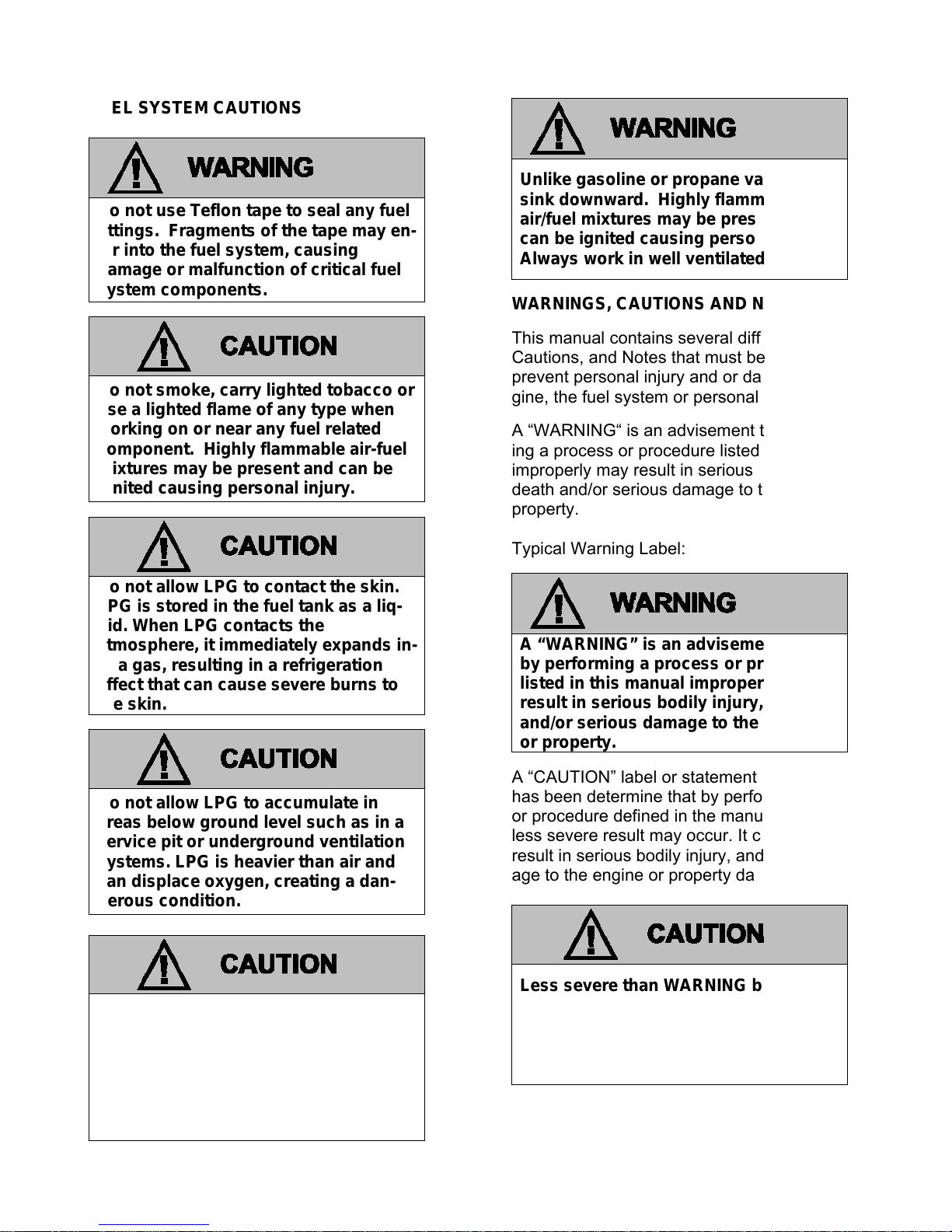
FUEL SYSTEM CAUTIONS
Do not use Teflon tape to seal any fuel
fittings. Fragments of the tape may en-
ter into the fuel system, causing
damage or malfunction of critical fuel
system components.
Do not smoke, carry lighted tobacco or
use a lighted flame of any type when
working on or near any fuel related
component. Highly flammable air-fuel
mixtures may be present and can be
ignited causing personal injury.
Do not allow LPG to contact the skin.
LPG is stored in the fuel tank as a liq-
uid. When LPG contacts the
atmosphere, it immediately expands in-
to a gas, resulting in a refrigeration
effect that can cause severe burns to
the skin.
Do not allow LPG to accumulate in
areas below ground level such as in a
service pit or underground ventilation
systems. LPG is heavier than air and
can displace oxygen, creating a dan-
gerous condition.
Unlike gasoline or propane vapors that
sink downward. Highly flammable
air/fuel mixtures may be present and
can be ignited causing personal injury.
Always work in well ventilated areas.
WARNINGS, CAUTIONS AND NOTES
This manual contains several different Warnings,
Cautions, and Notes that must be observed to
prevent personal injury and or damage to the engine, the fuel system or personal property.
A “WARNING“ is an advisement that by performing a process or procedure listed in this manual
improperly may result in serious bodily injury,
death and/or serious damage to the engine or
property.
Typical Warning Label:
A “WARNING” is an advisement that
by performing a process or procedure
listed in this manual improperly may
result in serious bodily injury, death
and/or serious damage to the engine
or property.
A “CAUTION” label or statement is used when it
has been determine that by performing a process
or procedure defined in the manual improperly a
less severe result may occur. It could however,
result in serious bodily injury, and or serious damage to the engine or property damage.
Do not make repairs to the fuel system
if you are not familiar with or trained to
service Propane fuel systems. Contact
the dealer who sold you the engine to
locate a repair facility with trained
technicians to repair your fuel system.
Less severe than WARNING but has
the potential to cause injury or damage. Also used to notify of situations
that could lead to eventual failure, injury or damage.
This caution label may also appear in area of this
manual that applies to service and repair proce-
7
Page 8
dures. In addition it may also be used to indicate
a failure to observe which may influence the terms
of the warranty.
An “IMPORTANT” statement generally denotes a
situation that requires strict adherence to the assembly, tightening, or service procedure. Failure
to observe this procedure could result in an unsafe condition or improper performance of the
engine or a component.
A “NOTE” statement applies to a specific item or
procedure that is to be followed during the servicing of the engine or its components.
PROPER USE OF THIS SERVICE MANUAL,
TOOLS AND EQUIPMENT
To reduce the potential for injury to the technician
or others and to reduce damage to the engine during service repairs the technician should observe
the following Steps:
The service procedures defined in this ma-
nual, when followed, have been found to be a
safe and efficient process to repair the fuel
system. In some cases special tools may be
required to perform the necessary procedures
to safely remove and replace a failed component.
Tools identified in this manual with the prefix
“J” or “BT” can be procured through SPX in
Warren, Michigan.
IMPCO tools identified in this manual with a
prefix “ITK” can be acquired through OEM
Parts Distribution.
IMPORTANT
It is important to remember that there may be a
combination of Metric and Imperial fasteners used
in the installation of the IMPCO fuel system.
Check to insure proper fit when using a socket or
wrench on any fastener to prevent damage to the
component being removed or injury from “slipping
off” the fastener.
The fuel system utilizes fuel lines and hoses with
high pressure connectors. Always use a wrench
of the proper size and torque to the correct value.
For hoses with swivel fittings, be sure not to turn
the fixed fitting which may cause a twisting or
kinking of the hose, possibly resulting in fuel line
restriction and/or leak.
Always leak check any fuel system connection after servicing! Use an
electronic leak detector and/or a liquid
leak detection solution. Failure to leak
check could result in serious bodily injury, death, or serious property damage.
8
Page 9

Maintenance
9
Page 10
MAINTENANCE
The maintenance of an engine and related components are critical to its operating performance
and lifespan. Industrial engines operate in environments that often include hot and cold
temperatures and extreme dust. The recommended maintenance schedule is listed in this
section, however, environmental operating conditions and additional installed equipment may
require more frequent inspection and servicing.
The owner and/or service agent should review the
operating conditions of the equipment to determine the inspection and maintenance intervals.
When performing maintenance on the engine,
turn the ignition OFF and disconnect the battery negative cable to avoid injury or damage
to the engine.
ENGINE BELTS
The engine installed in this equipment uses a serpentine drive belt configuration that drives the
water pump, alternator and additional pumps or
devices. It is important to note that the drive belt
is an integral part of the cooling and charging system and should be inspected according to the
maintenance schedule in this section. When inspecting the belts check for:
Cracks
Chunking of the belt
Splits
Material hanging loose from the belt
Glazing, hardening
If any of these conditions exist the belt should be
replaced with the recommended OEM replacement belt.
Alcohol or Methanol based anti-freeze or
plain water are not recommended for use in
the cooling system at anytime.
SERPENTINE BELT SYSTEM
Serpentine belts utilize a spring-loaded tensioner
to keep the belt properly adjusted. Serpentine
belts should be checked according to the maintenance schedule in this section.
IMPORTANT:
The use of “belt dressing” or “anti-slipping
agents” on belts is not recommended.
COOLING SYSTEM
It is important that the cooling system of the engine be maintained properly to ensure proper
performance and longevity.
Alcohol or Methanol based anti-freeze or
plain water are not recommended for use
in the cooling system at anytime.
Do not remove the cooling system pressure cap (radiator cap) when the engine is
hot. Allow the engine to cool and then
remove the cap slowly to allow pressure
to vent. Hot coolant under pressure may
discharge violently.
NOTE that the LPG vaporizer is connected to the
cooling system and the fuel system may be adversely affected by low coolant levels and
restricted or plugged radiator cores. Therefore,
the cooling system must be maintained according
to the recommend maintenance schedule in this
section and also include:
The regular removal of dust, dirt and debris
from the radiator core and fan shroud.
Inspection of coolant hoses and components
for leaks, especially at the radiator hose connections. Tighten hose clamps if necessary.
Check radiator hoses for swelling, separation,
hardening, cracks or any type of deterioration.
10
Page 11
If any of these conditions exist the hose
should be replaced with a recommended OEM
replacement part.
Inspect the radiator cap to ensure proper seal-
ing.
COOLANT
Check coolant level in coolant recovery tank and
add coolant as required. Add 50/50 mixture of
GM Dexcool antifreeze and water or coolant per
engine manufacturer’s instructions. Do not add
plain water. Replace coolant per the recommended schedule.
IMPORTANT:
The manufacturers of the engine and fuel system
do not recommend the use of “stop leak” additives
to repair leaks in the cooling system. If leaks are
present the radiator should be removed and repaired or replaced.
ENGINE ELECTRICAL SYSTEM MAINTNANCE
The engine’s electrical system incorporates computers to control various related components. The
electrical system connections and ground circuits
require good connections. Follow the recommended maintenance schedule in this section to
maintain optimum performance. When inspecting
the electrical system check the following:
Check Positive and Negative cables for corro-
sion, rubbing, chafing, burning and to ensure
tight connections at both ends.
Check battery for cracks or damage to the
case and replace if necessary.
Inspect engine wire harness for rubbing, chaf-
ing, pinching, burning, and cracks or breaks in
the wiring.
Verify that engine harness connectors are cor-
rectly locked in by pushing in and then pulling
the connector halves outward.
Inspect ignition coil wire for hardening, crack-
ing, arcing, chafing, burning, separation, split
boot covers.
Check spark plug wires for hardening, crack-
ing, chafing, arcing or burning, separation, and
split boot covers.
Replace spark plugs at the required intervals
per the recommended maintenance schedule.
Verify that all electrical components are se-
curely mounted to the engine or chassis.
Verify that any additional electrical services
installed by the owner are properly installed in
the system.
Verify that the MIL, charging, and oil pressure
lights illuminate momentarily during engine start.
ENGINE CRANKCASE OIL
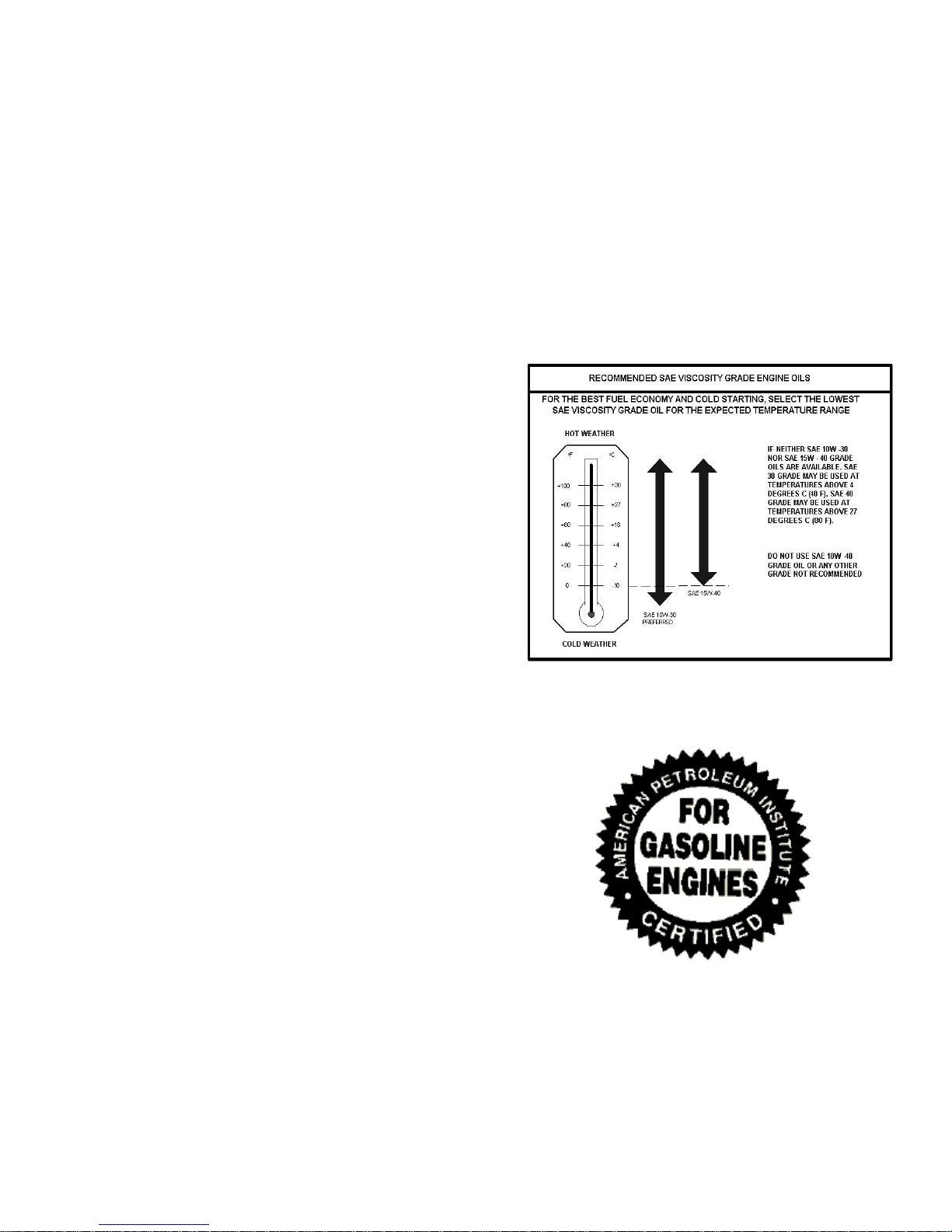
OIL RECOMMENDATION
Select an engine oil viscosity that will best match
the prevailing daytime temperature:
The oil must meet GM specification 9986231. Motor oils meeting this spec receive the API
(American Petroleum Institute) starburst symbol:
ILSAC GF-4 oils are highly recommended. Oils
meeting the SL-4 spec are improved over the previous generation GF-3 oils in many ways
Reduced Phosphorous levels (20%) for re-
duced catalyst poisoning
Improved oxidation resistance (4X oxidation
inhibitor treat level = 100% improvement)
11
Page 12
Improved hi temp deposit control (1.5X deter-
gents = 25% improvement)
It is noted that the GF-4 oils are also “backward
compatible” and are equal or better than previous
grades of oil in all aspects.
OEM’s may opt for higher viscosity oils based on
their application experience however GF-4 oils
may not be available in these viscosity ranges. In
this case it is recommended the OEM utilize high
quality oil (API rating SM).
CAUTION: Do not to operate your engine with an
oil level below the normal operating range. Severe engine damage could occur.
SYNTHETIC OILS
Synthetic oils have been available for use in industrial engines for a relatively long period of
time and may offer advantages in cold and hot
temperatures. However, it is not known if synthetic oils provide operational or economic
benefits over conventional petroleum-based oils
in industrial engines. Use of synthetic oils does
not permit the extension of oil change intervals.
CHECKING/FILLING ENGINE OIL LEVEL
IMPORTANT:
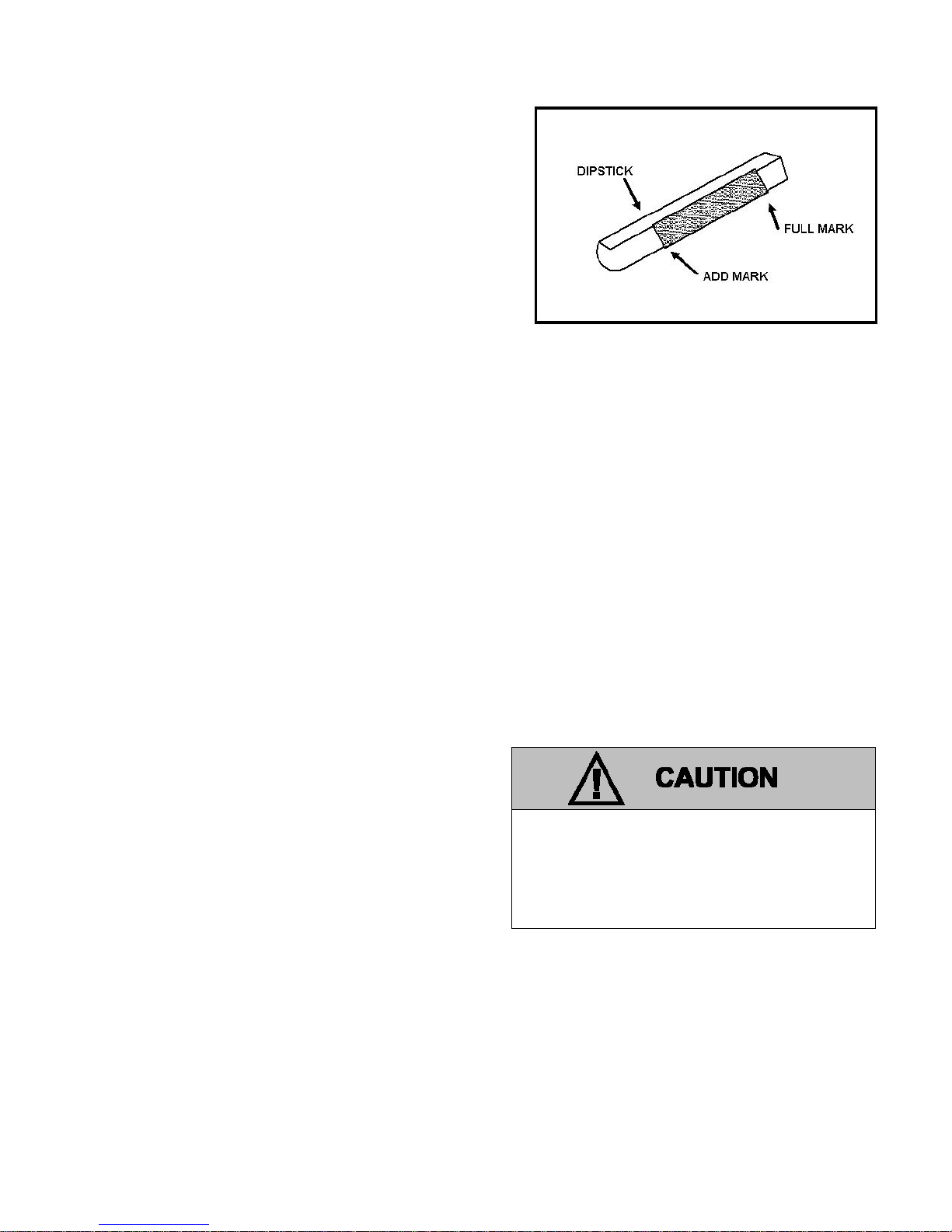
Care must be taken when checking engine oil level. Oil level must be maintained between the
“ADD” mark and the “FULL” mark on the dipstick.
To ensure that you are not getting a false reading,
make sure the following steps are taken before
checking the oil level.
1. Stop engine.
2. Allow approximately five minutes for the oil to
drain back into the oil pan.
3. Remove the dipstick. Wipe with a clean cloth
or paper towel and reinstall. Push the dipstick
all the way into the dipstick tube.
4. Remove the dipstick and note the amount of
oil on the dipstick. The oil level must be between the “FULL” and “ADD” marks.
Engine Oil Dip Stick (Typical)
5. If the oil level is below the “ADD” mark reinstall
the dipstick into the dipstick tube and proceed
to Step 6.
6. Remove the oil filler cap from the valve cover.
7. Add the required amount of oil to bring the
level up to, but not over, the “FULL” mark on
the dipstick. Reinstall the oil filler cap to the
valve rocker arm cover and wipe any excess
oil clean.
CHANGING THE ENGINE OIL
IMPORTANT:
When changing the oil, always change the oil
filter.
1. Start the engine and run until it reaches normal operating temperature.
An overfilled crankcase (oil level being too
high) can cause an oil leak, a fluctuation
or drop in oil pressure. When overfilled,
the engine crankshafts splash and agitate
the oil, causing it to aerate or foam.
IMPORTANT:
Change oil when engine is warm and the old oil
flows more freely.
2. Stop engine
12
Page 13

Engine oil will be hot. Use protective
gloves to prevent burns. Engine oil contains chemicals which may be harmful to
your health. Avoid skin contact.
3. Remove drain plug and allow the oil to drain.
4. Remove and discard oil filter and its sealing
ring.
5. Coat sealing ring on the new filter with clean
engine oil, wipe the sealing surface on the filter
mounting surface to remove any dust, dirt or
debris. Tighten filter securely (follow filter manufacturer’s instructions). Do not over tighten.
6. Check sealing ring on drain plug for any damage, replace if necessary, wipe plug with clean
rag, wipe pan sealing surface with clean rag
and re-install plug into the pan. Tighten to the
OEM specification.
7. Fill crankcase with oil.
8. Start engine and check for oil leaks.
9. Dispose of oil and filter in a safe and responsible manner.
FUEL SYSTEM INSPECTION AND
LPG FUEL SYSTEM
The LPG fuel system installed on this industrial
engine has been designed to meet the emission
standard applicable for the 2011 model year. To
ensure compliance to these standards, follow the
recommended maintenance schedule contained in
this section.
INSPECTION AND MAINTENANCE OF THE
FUEL STORAGE CYLINDER
The fuel storage cylinder should be inspected
daily or at the beginning of each operational shift
for any leaks, external damage, adequate fuel
supply and to ensure the manual service valve is
open. Fuel storage cylinders should always be
securely mounted, inspect the securing straps or
retaining devices for damage ensure that all locking devices are closed and locked. Check to
ensure that the fuel storage cylinder is positioned
with the locating pin in the tank collar on all horizontally mounted cylinders this will ensure the
proper function of the cylinder relief valve.
MAINTENANCE
When refueling or exchanging the fuel cylinder,
check the quick fill valve for thread damage. Also
verify O-ring is in place and inspect for cracks,
chunking or separation. If damage to the o-ring
is found, replace prior to filling. Check the service line quick coupler for any thread damage.
IMPORTANT:
When refueling the fuel cylinder, wipe both the
female and male connection with a clean rag prior
to filling to prevent dust, dirt and debris from being
introduced to the fuel cylinder.
INSPECTION OF THE FUEL FILTER
The LPG system on this emission certified engine
utilizes an in-line replaceable fuel filter element.
This element should be replaced, at the intervals
specified in the recommended maintenance schedule. When inspecting the fuel filter check the
following:
Check for leaks at the inlet and outlet fittings,
using a soapy solution or an electronic leak
detector and repair if necessary.
Check to make sure filter is securely mounted.
Check filter housing for external damage or
distortion. If damaged replace fuel filter.
AIR FUEL MIXER/THROTTLE CONTROL
DEVICE MAINTENANCE AND INSPECTION
IMPORTANT:
The Air Fuel Mixer components have been
specifically designed and calibrated to meet the
fuel system requirements of the emission certified
engine. The mixer should not be disassembled or
rebuilt. If the mixer fails to operate or develops a
leak the mixer should be replaced with the OEM
recommended replacement parts.
When inspecting the mixer check for the following
items:
Leaks at the inlet fitting.
Fuel inlet hose for cracking, splitting or chaff-
ing, replace if any of these condition exist.
Ensure the mixer is securely mounted.
Inspect air inlet hose connection and clamp.
Also inspect inlet hose for cracking, splitting or
chafing. Replace if any of these conditions exist.
13
Page 14
Inspect Air cleaner element according to the
Recommended Maintenance Schedule found
in this section.
Check Fuel lines for cracking, splitting or chaf-
ing. Replace if any of these conditions exist.
Verify Throttle body return action to ensure
throttle shaft is not sticking. Repair if necessary.
Check for leaks at the throttle body and intake
manifold.
PRESSURE REGULATOR MAINTENANCE AND
INSPECTION
IMPORTANT:
The Pressure Regulator components have been
specifically designed and calibrated to meet the
fuel system requirements of the emission certified
engine.
If the Regulator fails to operate or develops a
leak, it should be repaired or replaced with the
OEM recommended replacement parts. When
inspecting the regulator check for the following
items:
Check for any fuel leaks at the inlet and outlet
fittings.
Check for any fuel leaks in the regulator body.
Check the inlet and outlet fittings of the coo-
lant supply lines for water leaks.
Check the coolant supply lines for hardening,
cracking, chafing or splits. If any of these conditions exist replace coolant lines.
Check coolant supply hose clamp connec-
tions, ensure they are tight.
Check to ensure the Regulator is securely
mounted and the mounting bolts are tight.
Check the Regulator for external damage.
Check the Regulator electrical connections to
ensure the connector is seated and locked.
EXHAUST SYSTEM AND CATALYTIC
CONVERTER INSPECTION AND
MAINTENANCE
IMPORTANT:
The exhaust system on this emission certified engine contains Heated Exhaust Gas Oxygen
Sensors (HEGOs) which provide feedback to the
ECM on the amount of oxygen present in the exhaust stream after combustion.
The measurement of oxygen in the exhaust
stream is measured in voltage and sent to the
ECM. The ECM then makes corrections to the
fuel air ratio to ensure the proper fuel charge and
optimum catalytic performance. Therefore, it is
important that the exhaust connections remain
secured and air tight.
Contamination of the HEGO sensor can result from the use of an inappropriate RTV
sealer or silicone spray products. Do not use
silicone sprays or hoses which are assembled using silicone lubricants. Always use
“oxygen sensor safe” RTV sealant for repair
procedures. Silicon contamination will cause
a high but false HEGO signal voltage (rich
exhaust indication). The ECM will then reduce the amount of fuel delivery to the
engine, causing a severe driveability problem. If silicone contamination is suspected,
remove and visually inspect the sensor element. If contaminated, the portion of the
sensor exposed to the exhaust stream will
have a white powdery coating. Always be
sure to eliminate the cause of contamination
before replacing the sensor.
When inspecting the Exhaust system check the
following:
Exhaust manifold at the cylinder head for
leaks and that all retaining bolts and shields (if
used) are in place.
Manifold to exhaust pipe fasteners to ensure
they are tight and that there are no exhaust
leaks repair if necessary.
HEGO electrical connector to ensure connec-
tor is seated and locked, check wires to
ensure there is no cracking, splits chafing or
“burn through. Repair if necessary.
Exhaust pipe extension connector for leaks
tighten if necessary.
Visually inspect converter to ensure muffler is
securely mounted and tail pipe is properly
aimed.
Check for any leaks at the inlet and outlet of
the converter.
14
Page 15
V
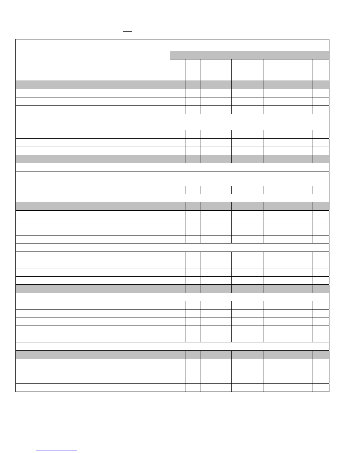
LPG CERTIFIED ENGINE MAINTENANCE REQUIREMENTS
For maintenance or other work that is not
the emission control devices and systems may be performed by any engine repair establishment or individual.
Perform the following maintenance on the engine at the hours indicated and at equivalent hour intervals thereafter.
This maintenance schedule represents the manufacturer’s recommended maintenance intervals to maintain proper engine/equipment
function. Federal, State, or Local regulations may require additional or
more frequent inspection or maintenance intervals than those specified above. Check with the authority having jurisdiction for details.
General Maintenance Section
isual check for fluid leaks X
Check engine oil level X
Check coolant level X
Change engine oil and filter
Check LPG system for leaks Prior to any service or maintenance activity
Inspect accessory drive belts for cracks, breaks, splits or glazing X X X X X
Inspect electrical system wiring for cuts, abrasions or corrosion X X
Inspect all vacuum lines and fittings for cracks, breaks or hardening X X
Engine Coolant Section
Clean debris from radiator core
Change coolant--GM 6277M specification (Dexcool) 50-50
mixture with distilled water
Inspect coolant hoses for cracks, swelling or deterioration X X X X X
Replace coolant hoses and accessory drive belt
Engine Ignition System
Inspect Battery case for leaks or damage X X X X X
Inspect battery cables for damage corrosion or contamination X X X X X
Check all electrical connector retainer locks X X X X X
Replace spark plugs X X X
Inspect crank sensor timing wheel for debris or damage
Clean ignition coil X X X X X
Check spark plug wires for cuts abrasions or hardening X
Replace distributor cap and rotor X
Replace spark plug wires X
Fuel System Maintenance
Inspect air cleaner
Replace fuel filters X X X X X
Inspect Shut-off Valve for leaks and closing X X
Leak check fuel lines, regulator, fuel rail and injectors X X
Check air induction and intake manifold for leaks X X
Check manifold for vacuum leaks X X
Drain Regulator oil build up
Engine Exhaust System
Inspect exhaust manifold for leaks X X
Inspect exhaust piping for leaks X X
Check HEGO sensor connectors and wires for burns, cuts or damage X X
Inspect catalyst for mechanical damage X X
Note that propane engines are designed to operate on HD–5 or HD–10 specification LPG fuel. Fuel other than HD–5 or HD–
10 may cause harm to the engine’s emission control system and a warranty claim may be denied on this basis if operators
can readily find the proper fuel*. Use of any other fuel may result in your engine no longer op erating in compliance with CARB
or EPA emissions requirements. * Not Applicable in the state of California.
performed under warranty, maintenance, replacement, or repair of
Interval Hours
Daily 1000 1500 2000 2500 3000 3500 4000 4500 5000
Every 100 hours or 60 days of operation
Every 100 hours or 60 days of operation
Every 5000 hours or five years
Every 2,000 hours or two years, whichever occurs first
Every 100 hours or 60 days of operation
Every 200 hours, or every 100 hours in dusty environment
Every 100 hours or 60 days of operation
15
Page 16

16
Page 17

LPG Fuel System
17
Page 18

LPG FUEL SYSTEM OPERATION
18
Page 19
DESCRIPTION AND OPERATION OF THE FUEL
SYSTEMS
LPG FUEL SYSTEM
The primary components of the LPG fuel system
are the fuel storage tank, regulator, throttle control
device, fuel injectors, engine control module (ECM),
catalytic converter and Heated Exhaust Gas Oxygen (HEGO) Sensor.
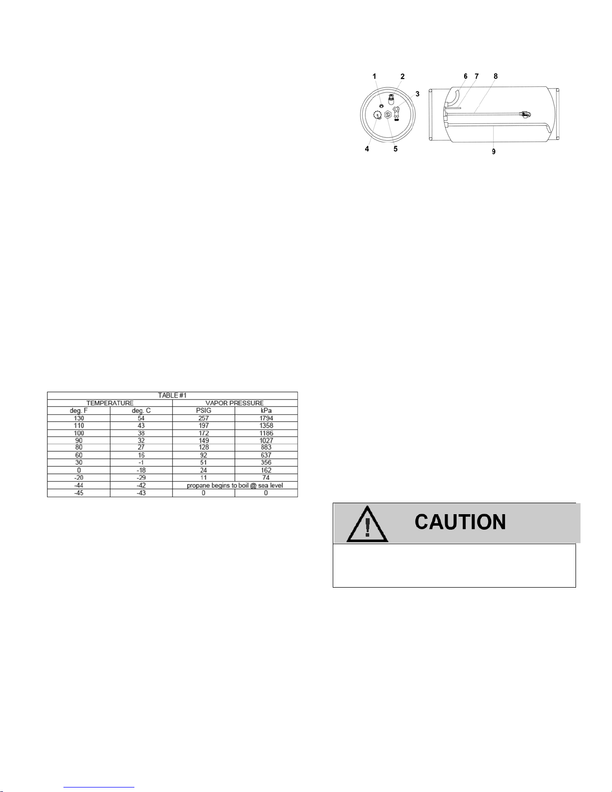
LPG FUEL TANK
LPG is stored in the fuel tank as a liquid. The approximate pressure of the fuel in the tank is 16.5
bar (240 psi) when the tank is full at an ambient
temperature of 27° C (81°F). The boiling point,
(temperature at which the liquid fuel becomes vapor) is approximately -40° C (-40° F). When the
fuel changes from liquid to vapor the fuel expands
and creates pressure inside the tank. When the
tank service valve is opened the pressure inside
the tank forces the liquid fuel out though the pickup
tube located near the bottom of the fuel cylinder.
The service valve mounted in the end of the cylinder controls the flow of fuel from the tank. By turning
the handle to its “open” position, fuel flows out of
the tank and into the service line. The service
valve is also equipped with a safety feature called
an excess flow check valve. This feature reduces
the flow from the service valve in the event of a rupture of the fuel line or any downstream fuel
transport components. A safety valve is built into
the tank. Normally set at 25.8 bar (375 psi), it will
release pressure to prevent tank rupture due to
over-pressurization of the cylinder
Typical LPG Cylinder
1. Liquid Outage Fill Check Valve
2. Pressure Relief Valve
3. Liquid Outage valve w/quick disconnect coupling
4. Filler Valve
5. Fuel Gauge
6. Vapor Withdrawal Tube (when applicable)
7. 80% Limiter Tube
8. Fuel Level Float
9. Liquid Withdrawal Tube
SERVICE LINE
LPG flows from the fuel tank to the Regulator via
the service line connected to the tank utilizing a
quick coupler. The other end of the service line is
connected to a bulkhead connector, allowing for a
safe means of passing through the sheet metal
and into the engine compartment. The service
line is made of high pressure hose with special
material or possibly tubing which is compatible
with the LPG fuel and should always be replaced
with an OEM supplied part.
The bulkhead assembly should never be
removed. Never run a service line through
the sheet metal.
FUEL FILTER
LPG, fuel like all other motor fuels is subject to
contamination from outside sources. Refueling of
the equipment tank and removal of the tank from
the equipment can inadvertently introduce dirt,
rust and other foreign matter into the fuel system.
It is therefore necessary to filter the fuel prior to
entering the fuel system components downstream
19
Page 20
of the tank. A replaceable, high pressure, inline
fuel filter is built into regulator and another is in
line between the regulator and fuel rail. Maintenance of the filters is critical to proper operation of
the fuel system and should be replaced according
to the maintenance schedule or more frequently
under severe operating conditions.
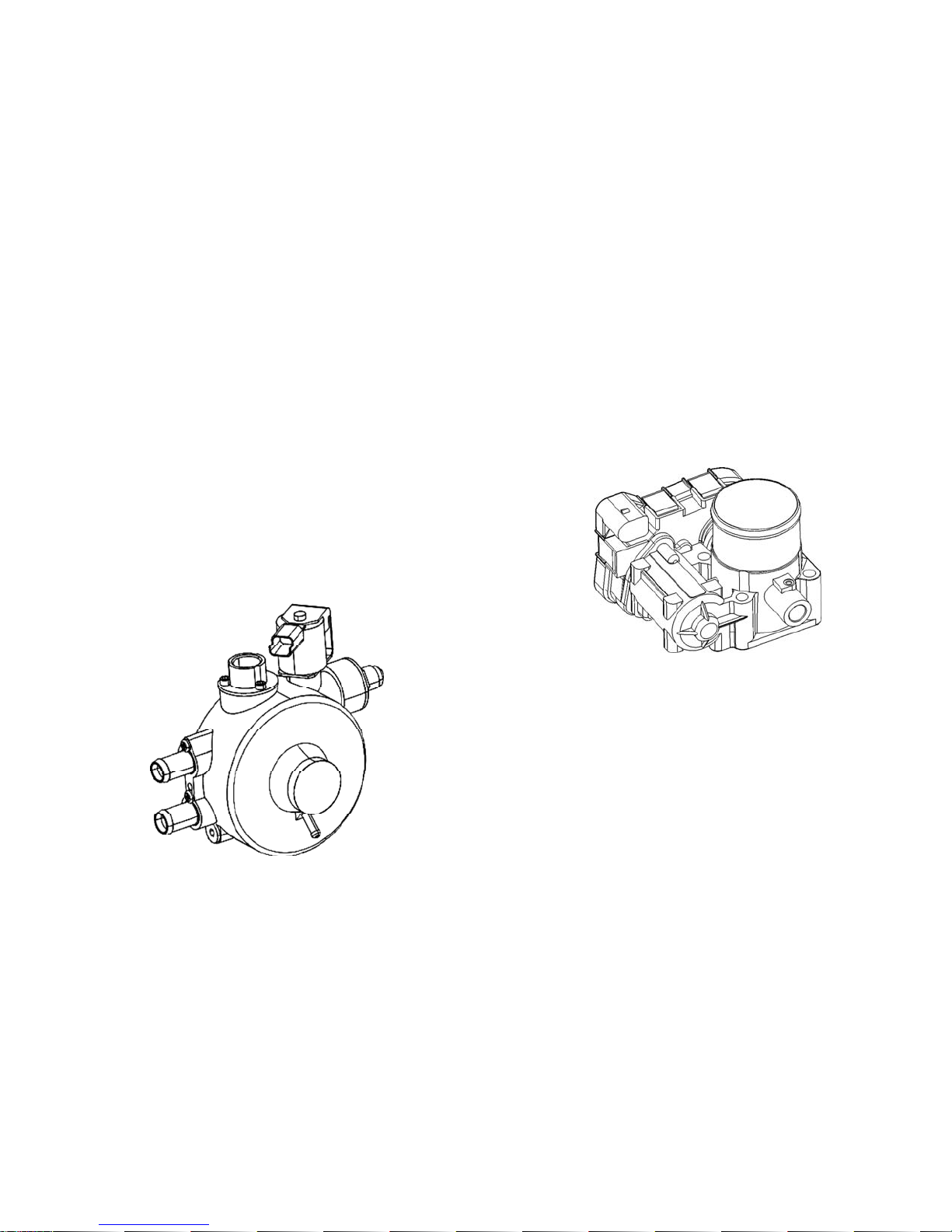
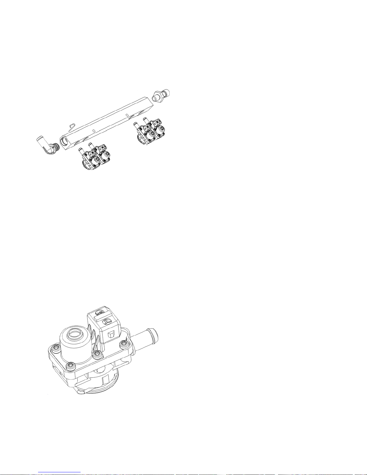
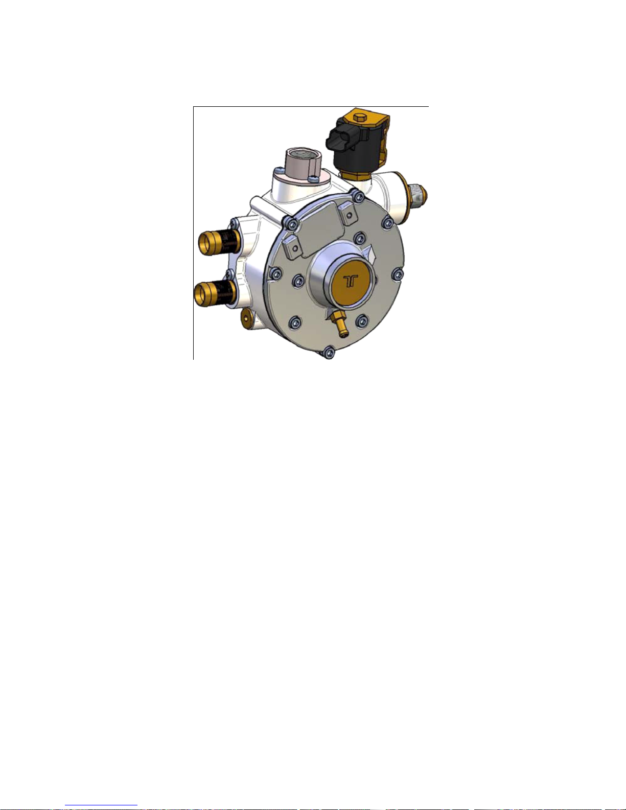
REGULATOR
The Regulator is a combination vaporizer and pressure regulating device with a built-in LPG shut-off
solenoid valve. The fuel shutoff is a normally
closed valve on the vaporizer, controlled by the
ECM. The valve is opened is opened momentarily
when the ignition is first turned on to allow the system to pressurize and when the engine is running.
When open, LPG passes into the regulator and any
liquid LPG is vaporized by heat provided by the engine coolant. The fuel vapor pressure is then
reduced to approximately 88 kPa (12.6 psi) and
delivered to the fuel rail and fuel injectors. The outlet fuel pressure is referenced to the manifold
pressure for a more stable idle.
connection with the throttle and there is no direct
mechanical (cable) connection between the pedal
and the throttle shaft.
The ECM monitors the foot pedal position sensor
when the engine is running. When the operator
depresses or releases the foot pedal, the ECM
sends an electrical signal to the motor on the
electronic throttle to increase or decrease the angle of the throttle blade thereby increasing or
decreasing the volume of air delivered to the engine. Two internal Throttle Position Sensors
(TPSs) provide feedback to the ECM indicating
the position of the throttle shaft and blade. Defaults programmed into the ECM software ensure
correct speed, load and emission control for all
throttle ranges.
Regulator
The regulator and some of components are serviceable.
THROTTLE CONTROL DEVICE—DRIVE BY
WIRE
S
peed control is maintained by the amount of pressure applied to the foot pedal located in the engine
compartment, however, in this Drive By Wire
(DBW) application, the foot pedal has an electronic
A throttle related failure will cause a “LIMP
HOME” mode of operation, where the engine has
no response to the pedal.
THREE WAY CATALYTIC CONVERTER
The Catalytic Converter is a component of the
emissions system which is designed and calibrated to meet the emission standards in effect
for 2011 model year.
The exhaust gases pass through the honeycomb
catalyst which is coated with a mixture of metals
(such as platinum, palladium, and rhodium) to
oxidize and reduce CO, HC and NOx emission
gases.
20
Page 21
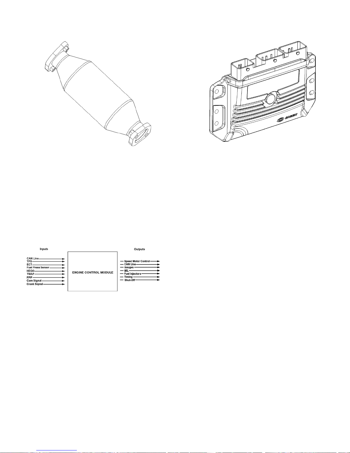
Three Way Catalytic Converter
ENGINE CONTROL MODULE
To obtain maximum effect from the catalyst and
accurate control of the air fuel ratio, the emission
certified engine is equipped with an onboard
computer or Engine Control Module (ECM). The
ECM is a controller which receives input data
from sensors mounted to the engine and fuel system and then outputs various signals to control
engine operation.
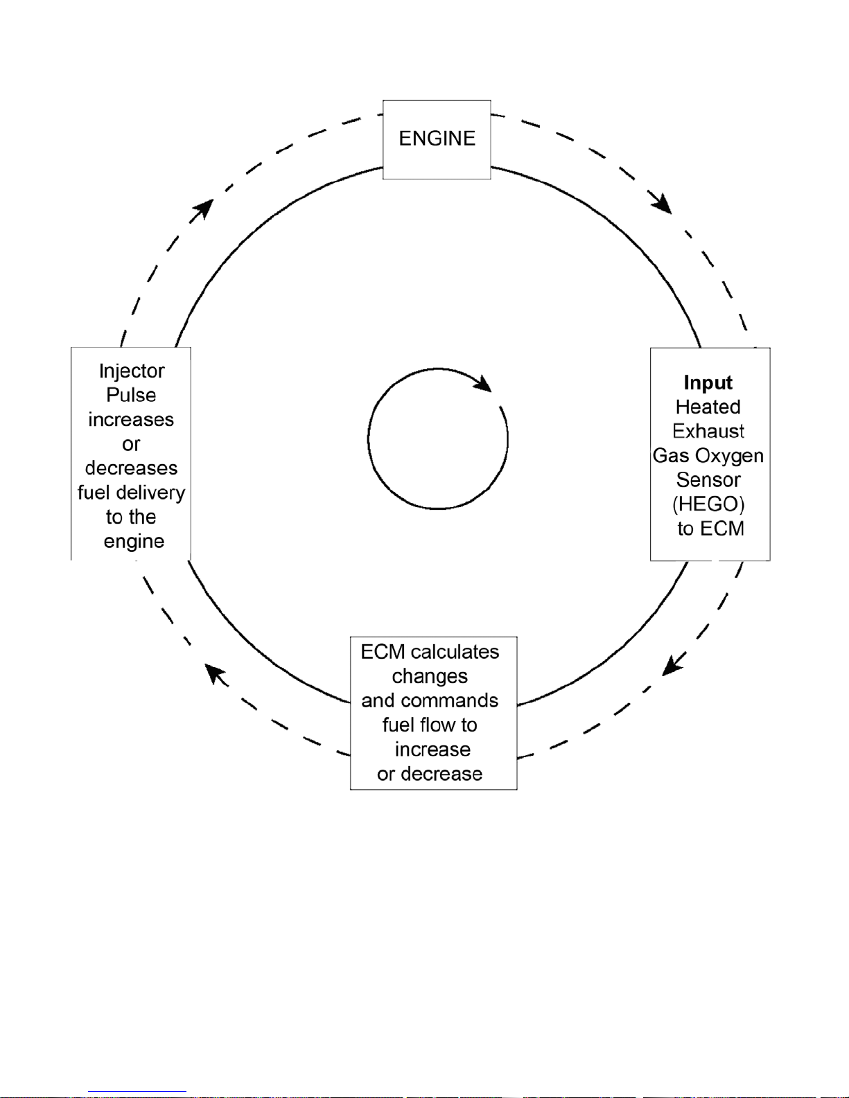
One specific function of the controller is to maintain a closed loop fuel control which is
accomplished by use of the Heated Exhaust Gas
Oxygen Sensors (HEGOs) mounted in the exhaust system. The HEGO sensors send a
voltage signal to the ECM which then changes
the amount of fuel being delivered from the injectors to the engine.
Engine Control Module (ECM)
The ECM also performs diagnostic functions on
the fuel system and notifies the operator of engine malfunctions by turning on a Malfunction
Indicator Light (MIL) mounted in the dash. Malfunctions in the system are identified by a
Diagnostic Trouble Code (DTC) number. In addition to notifying the operator of the malfunction in
the system, the controller also stores the information about the malfunction in its memory. A
technician can than utilize a computerized diagnostic scan tool to retrieve the stored diagnostic
code and by using the diagnostic charts in this
manual to determine the cause of the malfunction. In the event a technician does not have the
computerized diagnostic tool.
HEATED EXHAUST GAS OXYGEN SENSOR
The Heated Exhaust Gas Oxygen (HEGO) Sensor is mounted in the exhaust system to measure
the amount of oxygen present in the exhaust
stream. The ECM continuously monitors the
HEGO measurement to determine whether the
fuel air ratio is too rich, too lean and richen or
lean the mixture of fuel delivered to the engine. If
the ECM determines that a rich or lean condition
is present for an extended period of time which
cannot be corrected, the ECM will set a diagnostic code and turn on the MIL light in the dash.
21
Page 22
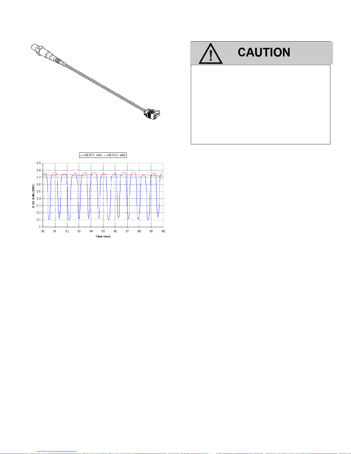
The Heat Exhaust Gas Oxygen (HEGO) Sensor
HEGO voltage output.
The Heated Exhaust Gas Oxygen Sensor
(HEGO) is an emissions control component. In the event of a failure, the HEGO
should only be replaced with the recommended OEM replacement part. The
HEGO is sensitive to silicone based products and can become contaminated.
Avoid using silicone sealers or air or fuel
hoses treated with a silicone based lubricant.
TMAP SENSOR
The Air Temperature/Manifold Absolute Pressure
or TMAP sensor is a combination of two sensors:
1) A variable resistor used to monitor the difference in pressure between the intake manifold
and outside or atmospheric pressure. The
ECM monitors the resistance of the sensor to
determine engine load (the vacuum drops
when the engine is under load or at wide
open throttle) and may alter the fuel mixture
to improve performance and emissions.
2) The Manifold Air Temperature (MAT or IAT)
sensor is a variable resistance thermistor located in the air intake passage which
measures the temperature of the incoming air.
The ECM uses the resistance value to monitor
incoming air temperature and calculate the engine’s airflow requirement. The ECM provides
a voltage divider circuit so that when the air is
cool, the signal reads a higher voltage, and
lower when warm. On cold starts, the ECM richens the fuel/air mixture.
22
Page 23
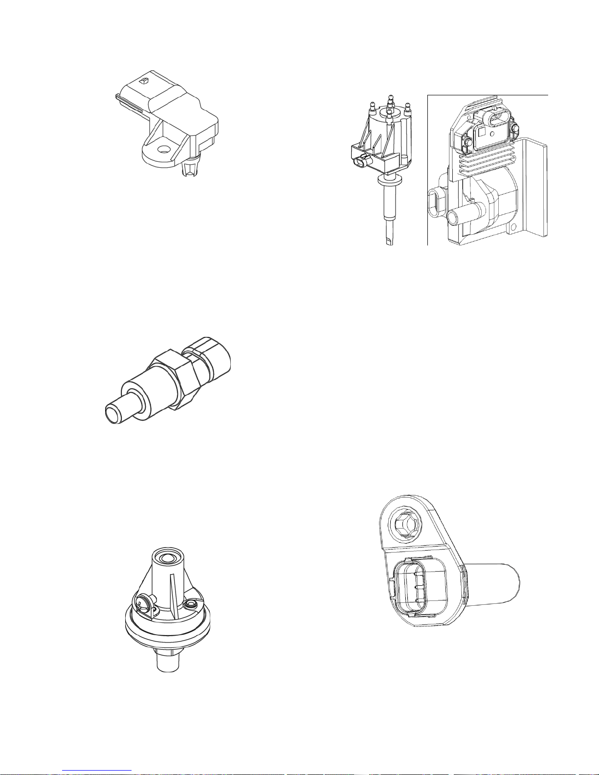
TMAP Sensor
COOLANT TEMPERATURE SENSOR
The Engine Coolant Temperature sensor or ECT is
a variable resistance thermistor that changes resistance as the engine's coolant temperature
changes. The sensor's resistance is monitored by
the ECM to determine a cold start condition and to
regulate various fuel and emission control functions
via a closed loop emission system.
Coolant Temperature Sensor
OIL PRESSURE SENDER
The Engine Oil Pressure Sender is designed to ensure adequate lubrication throughout the engine. It
is monitored by the ECM. If the pressure drops, a
MIL will occur.
IGNITION SYSTEM
The ignition system spark system uses a Crank
Position and Camshaft Position sensor for engine
timing. A coil assembly contain an ignition coil
and an ignition module supplies the ignition spark
for the system. The coil is fired for each cylinder
over two engine revolutions. The distributor
routes each spark event to the appropriate cylinder spark plug. The plug is fired near the top of
the compression stroke to ignite the fuel and air
mixture.
CAM SENSOR
In the 2011 engine the CAM sensor and a cam
signal wheel are incorporated into the ignition distributor mounted on the side of the engine block.
CRANK SENSOR
Oil Pressure Sender
Crank Sensor
The crank position sensor is a Hall effect sensor
that is triggered by a reluctor wheel on the crankshaft. Two missing teeth are used to determine
23
Page 24
engines rotational position. The crank sensor is the
source of all other ECU functions if this sensor is
not functioning the ECU will not see an engine
speed and will not provide fuel or spark to the engine.
Fuel Rail Assembly and LPG Injectors.
The gaseous LPG flows into the fuel rail where it is
distributed to the four LPG injectors. At the opposite end of the fuel rail to the inlet port there is a
Fuel Absolute Pressure (FAP) sensor (also known
as a Fuel Rail Pressure Sensor) this sensor allows
the ECU to lengthen or shorten the fuel injector
pulse width to compensate for variations in the absolute fuel pressure supplied to the injectors. This
injector assembly has one end inserted into the
manifold ports and the other end inserted into the
fuel rail ports. There is an o-ring seal on the manifold side and an o-ring and split spacer seal on the
fuel rail side. The fuel rail holds the injectors in
place.
stage, pilot actuated principal. When the coil is actuated it pulls the primary seal off the primary orifice
against the force of the flat return spring. This allows gas to flow out of the upper chamber of the
injector. Because the orifice supplying the upper
chamber is smaller than the primary orifice which is
now allowing fuel to flow out of the upper chamber,
the pressure drops in this chamber and the now
higher pressure in the lower chamber pushes the
main secondary seal off the secondary orifice and
allows full flow of the injector (this occurs in about 1
to 2 ms). When the coil is de-energized the primary
seal is returned to cover the primary orifice by the
force of the flat spring and pressure builds in the
upper chamber forcing the secondary seal down to
seal the secondary orifice and shutting off all flow of
gas.
A Spectrum IV Gaseous Fuel Injector
The 2011 saturated drive injectors operate on a two
24
Page 25
LPG Closed Loop Schematic
25
Page 26

26
Page 27

LPG System Diagnosis
27
Page 28
LPG FUEL SYSTEM DIAGNOSIS
Regulator Assembly
FUEL SYSTEM DESCRIPTION
The Engine Control Module (ECM) receives
information from various engine sensors in
order to control the operation of the engine.
LPG is stored in the tank as a liquid and delivered under pressure up to 21.5 BAR (312
psi). At Key ON the Regulator allows LPG to
flow from the tank through the fuel filter and
inside, where fuel is vaporized and reduced in
pressure.
DIAGNOSTIC AIDS
This procedure is intended to diagnose a vehicle operating on LPG. If the vehicle will not
continue to run refer to Hard Start for preliminary checks. Before starting this procedure,
complete the following tasks to verify that liquid fuel is being delivered to the EPR:
Inspect fuel tank to verify it has a sufficient
amount of fuel.
Verify the manual shut off valve on the
LPG tank is fully opened.
Verify that the excess flow valve has not
been activated.
Inspect fuel tank to ensure it is properly
mounted and rotated to the correct position.
Inspect the hoses leading from the tank
ensuring they are properly connected and
do not have any kinks or damage.
TOOLS REQUIRED:
7/16” Open end wrench (for test port
plugs)
Test port adapter
DST
Diagnostic Scan Tool (DST)
PRESSURE GAUGES
0-15 PSI Gauge
28
Page 29

FUEL SYSTEM DESCRIPTION
The Engine Control Module (ECM) receives information from various engine sensors in
order to control the operation of the Pressure Regulator and Shut-Off Valve. The ShutOff Valve solenoid prevents fuel flow unless the engine is cranking or running.
LPG is stored in the tank as a liquid and delivered under pressure of up to 21.5 BAR
(312 psi). At Key ON the Regulator allows LPG to flow from the tank through the fuel
filter and inside, where fuel is vaporized and reduced in pressure.
DIAGNOSTIC AIDS
This procedure is intended to diagnose a vehicle operating on LPG. If the vehicle will not
continue to run on LPG, refer to Hard Start for preliminary checks. Before starting this
procedure, complete the following tasks to verify that liquid fuel is being delivered to the
Regulator:
Inspect fuel tank to verify it has a sufficient amount of fuel.
Verify manual Shut Off valve on the LPG tank is fully opened.
Verify that the excess flow valve has not been activated.
Inspect fuel tank to ensure it is properly mounted and rotated to the correct position.
Inspect the hoses leading from the tank ensuring they are properly connected and do
not have any kinks or damage.
29
Page 30

LPG FUEL SYSTEM DIAGNOSTICS
Step Action Value(s) Yes No
Were you referred to this procedure by a DTC diagnostic
1
Chart?
Connect the Diagnostic Scan Tool (DST) to the ECM Data Link
Connector (DLC) and check for any DTCs.
2
Are any DTCs present in the ECM?
Perform the following visual and physical preliminary checks:
Check all ECM system fuses and circuit breakers (refer to
Engine Wiring Schematic).
Check the ECM grounds for being clean, tight and in their
proper locations (refer to Engine Wiring Schematic).
Check the vacuum hoses for damage, splits, kinks and prop-
er connections.
Check the fuel system for any type of leak or restriction from
the supply tank.
Check for air leaks at all mounting areas of the intake mani-
fold sealing surfaces.
Check for air leaks at all intake ducting between intake mani-
fold and air cleaner.
Check air cleaner and all vehicle intake ducting for restric-
3
4 Does the vehicle start and run?
5
tions.
Check exhaust system for flow obstructions or leaks.
Check the ignition wires for the following conditions:
Cracking or hardening
Proper routing
Bare or shorted wires
Carbon tracking
Check the wiring harness for the following conditions:
Proper connections
Pinches
Cuts or abrasions
Were any faulty conditions found in the preliminary checks?
Check the fuel system for the following conditions:
Verify the LPG fuel tank is at least ¼ full.
Verify the manual fuel shut-off valve is open and operating
correctly.
Verify the high-flow valve has not tripped.
Verify the quick disconnect is fully engaged and there are no
kinks or obstructions in the high pressure LPG supply hose.
Verify the LPG fuel filter is clean and unobstructed.
Were any faulty conditions found in the fuel supply system?
Go to Step
(3)
Go to appli-
cable DTC
Table
Correct
the faulty
condition
and Go to
Step 20
Go to Step
(9)
Correct
the faulty
condition
and Go to
Step 20
Go to
Step (2)
Go to
Step (3)
Go to
Step (4)
Go to
Step (5)
Go to
Step (6)
30
Page 31

Step Action Value(s) Yes No
Connect a calibrated 0-5” PSI pressure gauge to the pri-
mary pressure test port of the Regulator.
Make sure the manual shut-off valve is open and turn the
ignition to ON.
Crank the engine and observe the pressure gauge.
Does the pressure gauge indicate the proper primary fuel
6
pressure?
LPG is a gaseous fuel and requires higher secondary ignition voltages than gasoline fueled engines. Check the
ignition system for proper ignition secondary voltage output
with J 26792 or equivalent.
Remove the spark plugs and check for the following:
Correct plug type for LPG application.
Wet electrodes (oil fouling)
7
Cracks
Wear
Improper gap
Burned electrodes
Heavy deposits
Were any faulty conditions found in the ignition system
check?
Perform a leak-down test on the engine.
Are all cylinder leak-down test results within specification?
8
Turn OFF the manual fuel shut-off valve.
Start the engine and let it run until it dies.
Remove the LPG Temperature Sensor from the Regula-
tor (DO NOT disconnect the electrical connector).
9
Inspect the inside of the low-pressure fuel supply hose
for heavy-end deposits.
Are there any deposits built-up in the low-pressure fuel
supply hose?
2.0–4.0
PSI
<10%
leakage
Go to Step
(7)
Correct
the faulty
condition
and
Go to Step
(20)
Go to Step
(12)
Go to Step
(16)
If NO
pressure
was indi-
cated, Go
to Step
(14)
If LOW
or HIGH
pressure
was in-
dicated,
Go to
Step
(15)
Go to
Step (8)
Repair
the engine as
neces-
sary and
Go to
Step
(20)
Go to
Step
(10)
31
Page 32

Step Action Values Yes No
Remove the FAP sensor from the Fuel Rail and insert the
Pressure Test Adapter and connect to 103 kPa (15 PSI)
10
11
12
13
14
15
pressure gauge.
Connect the DST to the vehicle DLC connector and open the
DST software.
Turn the manual shut-off valve ON. Start the engine and
allow it to reach operating temperature.
Compare the gauge secondary pressure reading to the actual
pressure on the DST.
Is the gauge secondary pressure within the specified percentage of the actual pressure indicated on the DST?
Turn OFF the manual shut-off valve and let the engine run
until it dies.
Turn the ignition OFF.
If turned OFF, turn ON the manual shut-off valve.
Disconnect the Lock-off valve electrical connector.
Apply 12V to the lock-off valve terminals and observe the
pressure gauge.
Does the pressure gauge indicate pressure?
Repair or replace the Shut Off Valve (refer to Repair Instructions).
Is the action complete?
+/-15 kPa
(2.2 PSI)
Go to Step
19
Go to Step
(14)
Go to
Step (11)
Go to
Step (13)
Above
1.0 PSI
Go to Step
17
Go to Step
20
Go to
Step 18
NA
32
Page 33

Step Action Values Yes No
Inspect the following for heavy-end deposits:
16
17
18
19
20
21
22
23
Pressure Regulator. Inspect, clean and/or repair as neces-
sary (refer to Regulator Repair Instructions).
Are all actions complete?
Replace the ECM.
Is the action complete?
Replace the Shut Off Valve.
Is the action complete?
System working correctly at this time. Vehicle may have
intermittent electrical connection conditions.
Return vehicle to original condition (but leave the diagnostic
equipment connected).
Start the engine and wiggle test the harness while observing
the DST Faults Screen and the pressure gauge readings.
Repair any conditions encountered.
Is the action complete?
Clear any active or historic DTCs (DST Service or Faults
Screen).
Clear Adaptive from memory (DST Service Screen).
Return the vehicle to original condition.
Operate the vehicle under all load and driving conditions for
at least 10 minutes.
Park the vehicle with the engine running and connect the
DST to the vehicle’s DLC connector.
Open the DST software and switch to the Faults Screen.
Let the vehicle idle with no load for at least 30 seconds and
observe the Adaptive 1 fuel correction.
Did the Adaptive 1 fuel correction remain within the specified
values?
With engine still idling, apply a load with the hydraulic system
for at least 10 seconds and observe the Adaptive 1 value.
Did the Adaptive 1 fuel correction remain within the specified
values?
Raise the engine rpms to 75-90% of maximum full governed
speed with no load for at least 10 seconds and observe the
Adaptive 1 fuel correction.
Did the Adaptive 1 fuel correction remain within specified values?
With the engine still running at 75-90% of full governed
speed, apply a moderate load with the hydraulic system.
Observe the Adaptive 1 fuel correction.
Did the Adaptive 1 fuel correction remain within specified values?
-15% to
+15%
-15% to
+15%
-15% to
+15%
-15% to
+15%
Go to Step
20
Go to Step
20
Go to Step
20
Go to Step
20
Go to Step
21
Go to Step
22
Go to Step
23
Go to Step
29
33
NA
NA
NA
NA
Go to
Step 24
Go to
Step 24
Go to
Step 24
Go to
Step 24
Page 34

Step Action Values Yes No
24 Was the Adaptive 1 fuel correction less than -15%?
Go to Step
(26)
Go to
Step (25)
25 Was the Adaptive 1 fuel correction more than +15%?
Engine is running RICH (system is trying to compensate by decreasing the amount of fuel). Check the following for any
condition which may cause the engine to run RICH:
Ignition system (See Step 7).
26
Air cleaner and intake system (including vehicle intake
ducting) for airflow obstructions.
Exhaust system for flow obstructions.
HEGO for correct switching characteristics.
Are all actions complete?
Engine is running LEAN (system is trying to compensate by
increasing the amount of fuel). Check the following for any
condition which may cause the engine to run LEAN:
Intake manifold for leaks.
All throttle body gaskets or o-rings for leaks.
All vacuum hoses and fittings for leaks.
Exhaust system for leaks
27
NOTE: Exhaust system leaks allow for excess O
to dilute the
2
HEGO sensor giving a false reading. Engine may exhibit signs
of a rich running condition but the Adaptive 1 corrections will
indicate an excessive positive fuel adjustment.
HEGO for correct switching characteristics.
Are all actions complete?
Go to Step
(27)
Go to Step
(28)
Go to Step
(28)
NA
NA
NA
28 Repeat Step 20. NA NA
Remove all test equipment except the DST.
Connect any disconnected components, fuses, etc.
Using the DST clear DTC information from the ECM.
Turn the ignition OFF and wait 30 seconds.
Start the engine and operate the vehicle to full operating
29
temperature
NA NA
Observe the MIL
Observe engine performance and driveability
Does the engine operate normally with no stored codes?
Remove all diagnostic equipment and return vehicle to original
condition. Return vehicle to customer.
34
Page 35

Fuel Symptom Diagnostics
35
Page 36

FUEL SYMPTOM DIAGNOSTICS
Checks Action
Before using this section, you should have performed On Board Diagnostic
(OBD) Check and determined that:
1. The ECM and MIL are operating correctly.
Before Using This
Section
Fuel System Check
2. There are no Diagnostic Trouble Codes (DTCs) stored, or a DTC exists
but without a MIL.
Several of the following symptom procedures call for a careful visual and
physical check. These checks are very important as they can lead to prompt
diagnosis and correction of a problem.
1. Verify the customer complaint.
2. Locate the correct symptom table.
3. Check the items indicated under that symptom.
4. Operate the engine under the conditions the symptom occurs. Verify
HEGO switching between lean and rich (cycling of voltage).
IMPORTANT! Normal HEGO switching indicates the fuel system is
in closed loop and operating correctly at that time.
5. Take a data snapshot using the DST under the condition that the symptom occurs to review at a later time.
Visual and Physical
Checks
Check all ECM system fuses and circuit breakers.
Check the ECM ground for being clean, tight and in its proper location.
Check the vacuum hoses for splits, kinks and proper connections.
Check thoroughly for any type of leak or restriction.
Check for air leaks at all the mounting areas of the intake manifold sealing
surfaces.
Check for proper installation and leakage around the Regulator and Throt-
tle body.
Check the ignition wires for the following conditions:
Cracking
Hardening
Proper routing
Carbon tracking
Check the wiring for the following items: proper connections, pinches or
cuts.
The following symptom tables contain groups of possible causes for each
symptom. The order of these procedures is not important. If the DST readings do not indicate a problem, then proceed in a logical order, easiest to
check or most likely to cause the problem.
36
Page 37

INTERMITTENT
Checks Action
DEFINITION: The problem may or may not turn ON the (MIL) or store a Diagnostic Trouble Code
(DTC).
Preliminary Checks
Faulty Electrical Con-
nections or Wiring
Operational Test
Intermittent MIL
Illumination
Do not use the DTC table if a fault is an intermittent, the use of the DTC
tables with this condition may result in the replacement of good parts.
Faulty electrical connections or wiring can cause most intermittent problems.
Check the suspected circuit for the following conditions:
Faulty fuse or circuit breaker, connectors poorly mated, terminals not fully
seated in the connector (backed out). Terminals not properly formed or
damaged.
Wire terminals poorly connected.
Terminal tension is insufficient.
Carefully remove all the connector terminals in the problem circuit in or-
der to ensure the proper contact tension.
If necessary, replace all the connector terminals in the problem circuit in
order to ensure the proper contact tension (except those noted as “Not
Serviceable”). See section Wiring Schematics.
Checking for poor terminal to wire connections requires removing the
terminal from the connector body.
If a visual and physical check does not locate the cause of the problem, operate the engine with the DST connected. When the problem occurs, an
abnormal voltage or scan reading indicates a problem circuit.
The following components can cause intermittent MIL and no DTC(s):
A defective relay.
Switch that can cause electrical system interference. Normally, the prob-
lem will occur when the faulty component is operating.
The improper installation of add on electrical devices, such as lights, 2-
way radios, electric motors, etc.
The ignition secondary voltage shorted to a ground.
The MIL circuit or the Diagnostic Test Terminal intermittently shorted to
ground.
The MIL wire grounds.
To check for the loss of the DTC Memory:
1. Disconnect the TMAP sensor.
Loss of DTC Memory
2. Run engine under no load until the MIL illuminates.
3. The ECM should store a TMAP DTC which should remain in the memory
when the ignition is turned OFF. If the TMAP DTC does not store and
remain, the ECM is faulty.
37
Page 38

NO START
Checks Action
DEFINITION: The engine cranks OK but does not start.
Preliminary Checks None
Use the DST to :
Check for proper communication with both the ECM
ECM Checks
Sensor Checks
Fuel System Checks
Ignition System Checks
Check all system fuses engine fuse holder. Refer to Engine Controls
Schematics.
Check battery power, ignition power and ground circuits to the ECM. Re-
fer to Engine Control Schematics. Verify voltage and/or continuity for
each.
Check the TMAP sensor.
Check the cam/crank sensors for output (rpm). This can be verified by an
RPM signal on the DST.
Check the cam angle sensor for output (rpm).
Verify proper operation of the Shut-off solenoid Valves.
Important: A closed Gas supply valve will create a no start condition.
Check for air intake system leakage around the Regulator and throttle
body.
Check the fuel system pressures.
Refer to the Fuel System Diagnosis.
NOTE: Natural Gas and Propane require higher secondary ignition system
voltages for the equivalent gasoline operating conditions.
1. Check for the proper ignition voltage output with J 26792 or the equiva-
lent.
2. Verify that the spark plugs are correct.
Check the spark plugs for the following conditions:
Wet plugs (Oil Fouling)
Cracks.
Wear.
Improper gap.
Burned electrodes.
Heavy deposits.
Check for bare or shorted ignition wires.
Check for loose ignition coil connections at the coil.
38
Page 39

Checks Action
Engine Mechanical
Checks
Exhaust System Checks
Important: The LPG Fuel system is more sensitive to intake manifold lea-
kage than the gasoline fuel system.
Check for the following:
Manifold vacuum leaks.
Venturi vacuum leaks.
Engine Vacuum leaks.
Improper valve timing.
Low compression.
Improper valve clearance.
Worn rocker arms.
Broken or weak valve springs.
Worn camshaft lobes.
Check the exhaust system for a possible restriction:
Inspect the exhaust system for damaged or collapsed pipes.
Inspect the muffler for signs of heat distress or for possible internal fail-
ure.
39
Page 40

HARD START
Checks Action
DEFINITION: The engine cranks OK, but does not start for a long time. The engine does eventually run,
or may start but immediately dies.
Preliminary Checks Make sure the engine’s operator is using the correct starting procedure.
Check the Engine Coolant Temperature sensor with the DST. Compare
the engine coolant temperature with the ambient air temperature on a
cold engine. If the coolant temperature reading is more than 10 degrees
Sensor Checks
Fuel System Checks
greater or less than the ambient air temperature on a cold engine, check
for high resistance in the coolant sensor circuit. Check the cam/crank
sensors.
Check the Throttle Position (TPS) and Foot Pedal Position (FPP) sensor
connections.
Important: A closed LPG manual fuel shut off valve will create a no start
condition.
Check Venturi assembly for proper installation and leakage.
Verify proper operation of the Shut-off solenoid Valves.
Verify proper operation of the system low pressure Regulator.
Check for air intake system leakage between the Throttle Body and Air
Filter Assembly. Check the fuel system pressures. Refer to the Fuel
System Diagnosis.
Ignition System Checks
NOTE: LPG requires higher secondary ignition system voltages for the
equivalent gasoline operating conditions.
Check for the proper ignition voltage output with J 26792 tool or the
equivalent.
Verify that the spark plugs are the correct type and properly gapped.
Check the spark plugs for the following conditions:
Wet plugs (oil fouling).
Cracks.
Wear.
Burned electrodes.
Heavy deposits.
Check for bare or shorted ignition wires.
Check for moisture in the distributor cap.
Check for loose ignition coil connections.
Important:
1. If the engine starts but then immediately stalls, check the cam/crank sensor.
2. Check for improper gap, debris or faulty connections.
40
Page 41

Checks Action
Engine Mechanical
Checks
Exhaust System Checks
Important: The LPG Fuel system is more sensitive to intake manifold lea-
kage than the gasoline fuel supply system.
Check for the following:
Engine vacuum leaks
Manifold vacuum leaks.
Venturi Vacuum Leaks
Improper valve timing-how?
Low compression
Improper valve clearance.
Worn rocker arms
Broken or weak valve springs
Worn camshaft lobes.
Check the exhaust system for a possible restriction:
Inspect the exhaust system for damaged or collapsed pipes.
Inspect the muffler for signs of heat distress or for possible internal fail-
ure.
Check for possible plugged catalytic converter. Refer to Restricted Exhaust
System Diagnosis.
41
Page 42

CUTS OUT, MISSES
Checks Action
DEFINITION: A surging or jerking that follows engine speed, usually more pronounced as the engine load
increases, but normally felt below 1500 rpm. The exhaust has a steady spitting sound at low speed, or
hard acceleration for the fuel starvation that can cause the engine to cut-out.
Preliminary Checks None
1. Start the engine.
2. Check for proper ignition output voltage with spark tester J 26792.
3. Check for a cylinder misfire.
4. Verify that the spark plugs are the correct type and properly gapped.
Remove the spark plugs and check for the following conditions:
Insulation cracks.
Ignition System Checks
Engine Mechanical
Checks
Fuel System Checks
Wear.
Improper gap.
Burned electrodes.
Heavy deposits.
Visually/Physically inspect the secondary ignition for the following:
Ignition wires for arcing and proper routing.
Cross-firing.
Ignition coils for cracks or carbon tracking.
Perform a cylinder compression check. Check the engine for the following:
Improper valve timing.
Improper valve clearance.
Worn rocker arms.
Worn camshaft lobes.
Broken or weak valve springs.
Check the intake and exhaust manifold passages for casting flash.
Check the fuel system:
Plugged fuel filter (if equipped).
Low fuel pressure, etc. Refer to Fuel System Diagnosis.
Check the condition of the wiring to the Shut-off Valves.
Check for Electromagnetic Interference (EMI), which may cause a misfire condition. Using the DST, monitor the engine rpm and note sudden increases in
Additional Check
rpm displayed on the scan tool but with little change in the actual engine rpm.
If this condition exists, EMI may be present. Check the routing of the secondary wires and the ground circuit.
42
Page 43

HESITATION, SAG, STUMBLE
Checks Action
DEFINITION: The engine has a momentary lack of response when accelerating the engine. The condition can occur at any engine speed. The condition may cause the engine to stall if it’s severe enough.
Preliminary Checks None.
Check the fuel pressure. Refer to Fuel System Diagnosis.
Check for low fuel pressure during a moderate or full throttle accelera-
tion. If the fuel pressure drops below specification, there is possibly a
Fuel System Checks
Ignition System Checks
faulty low pressure regulator or a restriction in the fuel system.
Check the TMAP sensor response and accuracy.
Check Shut-Off electrical connections.
Check the Regulator, Venturi and Throttle body for proper installation
and leakage.
NOTE: Natural Gas and Propane require higher secondary ignition system
voltages for the equivalent gasoline operating conditions.
Check for the proper ignition voltage output with J 26792 or the equiva-
lent. Verify that the spark plugs are the correct type and properly gapped.
Check for faulty spark plug wires.
Check for oil fouled spark plugs.
Additional Check
Check for manifold vacuum or air induction system leaks.
Check the alternator output voltage.
43
Page 44

BACKFIRE
Checks Action
DEFINITION: The fuel ignites in the intake manifold, or in the exhaust system, making a loud popping
noise.
Preliminary Check None.
NOTE: LPG requires higher secondary ignition system voltages for the
equivalent gasoline operating conditions.
Check for the proper ignition coil output voltage using the spark tester
J26792 or the equivalent.
Check the spark plug wires by connecting an ohmmeter to the ends of
each wire in question. If the meter reads over 30,000 ohms, replace the
wires.
Check the connection at ignition coil.
Ignition System Checks
Engine Mechanical
Check
Fuel System Checks Perform a fuel system diagnosis. Refer to Fuel System Diagnosis.
Check for deteriorated spark plug wire insulation.
Remove the plugs and inspect them for the following conditions:
Wet plugs (oil fouling).
Cracks.
Wear.
Improper gap.
Burned electrodes.
Heavy deposits.
Important! The LPG Fuel system is more sensitive to intake manifold
leakage than a gasoline fuel supply system.
Check the engine for the following:
Improper valve timing.
Engine compression.
Manifold vacuum leaks.
Intake manifold gaskets.
Sticking or leaking valves.
Exhaust system leakage.
Check the intake and exhaust system for casting flash or other restric-
tions.
44
Page 45

LACK OF POWER, SLUGGISHNESS, OR SPONGINESS
Checks Action
DEFINITION: The engine delivers less than expected power. There is little or no increase in speed
when throttling the engine.
Refer to the Fuel system OBD System Check.
Compare the customer’s engine with a similar unit to verify customer has
an actual problem. Do not compare the power output of the engine op-
Preliminary Checks
Fuel System Checks
erating on Natural Gas and Propane to one operating on gasoline as the
fuels do have different performance characteristics.
Remove the air filter and check for dirt or restriction.
Check the vehicle transmission.
Refer to the OEM transmission diagnostics.
Check for a restricted fuel filter, contaminated fuel, or improper fuel pres-
sure. Refer to LPG Fuel System Diagnosis.
Check for the proper ignition output voltage with the spark tester J 26792
or the equivalent.
Check the Regulator and Throttle body for proper installation and lea-
kage. Check all air inlet ducts for condition and proper installation.
Check all air inlet ducts for condition and proper installation.
Check for fuel leaks in supply lines.
Verify that the Fuel Supply Valve on the supply line is open.
Verify that liquid fuel (not vapor) is being delivered to the Regulator.
Sensor Checks
Exhaust System Checks
Engine Mechanical
Check
Additional Check
Check the Heated Exhaust Gas Oxygen Sensor (HEGO) for contamina-
tion and performance. Check for proper operation of the TMAP sensor.
Check for proper operation of the TPS and FPP sensors.
Check the exhaust system for a possible restriction:
Inspect the exhaust system for damaged or collapsed pipes.
Inspect the muffler for signs of heat distress or for possible internal fail-
ure.
Check for possible plugged catalytic converter.
Check the engine for the following:
Engine compression.
Valve timing.
Improper or worn camshaft.
Refer to Engine Mechanical in the Service Manual.
Check the ECM grounds for being clean, tight, and in their proper loca-
tions.
Check the alternator output voltage.
If all procedures have been completed and no malfunction has been found,
review and inspect the following items:
Visually and physically, inspect all electrical connections within the sus-
pected circuit and/or systems.
Check the DST data.
45
Page 46

POOR FUEL ECONOMY
Checks Action
DEFINITION: Fuel economy, as measured by refueling records, is noticeably lower than expected.
Also, the economy is noticeably lower than it was on this vehicle at one time, as previously shown by
refueling records.
Check the air cleaner element (filter) for dirt or being plugged.
Visually check the vacuum hoses for splits, kinks, and proper connec-
tions.
Properly inflated tires.
Preliminary Checks
Fuel System Checks
Sensor Checks
Ignition System
Checks
Cooling System
Checks
Check the operators driving habits for the following:
Excessive idling or stop and go driving.
Carrying of very heavy loads.
Rapid acceleration.
Suggest to the owner to fill the fuel tank and to recheck the fuel economy
and/or suggest that a different operator use the equipment and record the
results.
Check the Regulator fuel pressure. Refer to Fuel System Diagnosis.
Check the fuel system for leakage.
Check the TMAP sensor.
Verify that the spark plugs are the correct type and properly gapped.
Remove the plugs and inspect them for the following conditions:
Wet plugs (oil fouling).
Cracks.
Wear.
Improper gap.
Burned electrodes.
Heavy deposits.
Check the ignition wires for the following items:
Cracking.
Hardness.
Proper connections.
Check the engine thermostat to see if it is stuck open or for the wrong heat
range.
46
Page 47

ROUGH, UNSTABLE, OR INCORRECT ENGINE SPEED, STALLING
Checks Action
DEFINITION: The engine runs unevenly at under no load. If severe enough, the engine may shake.
The engine speed may vary in rpm. Either condition may be severe enough to stall the engine.
Preliminary Check None.
Check the Heated Exhaust Gas Oxygen Sensor (HEGO) performance:
Check for silicone contamination from fuel or improperly used sealant. If
contaminated, the sensor may have a white powdery coating result in a high
Sensor Checks
Fuel System Checks
but false signal voltage (rich exhaust indication). The ECM will reduce the
amount of fuel delivered to the engine causing a severe performance problem.
Check the Temperature Manifold Absolute Pressure (TMAP) sensor response
and accuracy.
Check for rich or lean symptom that causes the condition.
Run the engine at the speed of the complaint.
Monitoring the oxygen sensor will help identify the problem.
Verify proper operation of the Regulator.
Perform a cylinder compression test. Refer to Engine Mechanical in the
Service Manual.
Check the Regulator fuel pressure. Refer to the Fuel System Diagnosis.
Check the Regulator, Venturi and Throttle body for proper installation and
leakage.
Ignition System
Checks
Additional Checks
Check for the proper ignition output voltage using the spark tester J26792 or
the equivalent.
Verify that the spark plugs are the correct type and properly gapped.
Remove the plugs and inspect them for the following conditions:
Wet plugs (oil fouling).
Cracks.
Wear.
Improper gap.
Burned electrodes.
Blistered insulators.
Heavy deposits.
Check the spark plug wires by connecting an ohmmeter to the ends of each
wire in question. If the meter reads over 30,000 ohms, replace the wires.
Important: The LPG Fuel system is more sensitive to intake manifold leakage
than the gasoline fuel supply system.
Check for vacuum leaks. Vacuum leaks can cause poor engine perfor-
mance.
Check the ECM grounds for being clean, tight, and in their proper locations.
Check the battery cables and ground straps. They should be clean and secure. Erratic voltage may cause all sensor readings to be skewed resulting
in poor engine performance.
47
Page 48

Engine Mechani-
cal Check
Checks Action
Check the engine for:
Broken motor mounts.
Improper valve timing.
Low compression.
Improper valve clearance.
Worn rocker arms.
Broken or weak valve springs.
Worn camshaft lobes.
48
Page 49

SURGES/CHUGGLES
Checks Action
DEFINITION: The engine has a power variation under a steady throttle. The engine feels as if it speeds
up and slows down with no change to the throttle.
Preliminary Checks None.
Sensor Checks Check the Heated Exhaust Gas Oxygen Sensor (HEGO) performance.
Check for Rich or Lean symptom that causes the condition.
Run the engine at the speed of the complaint. Monitoring the oxygen sen-
sor will help identify the problem.
Fuel System Checks
Ignition System
Checks
Check the fuel pressure while the condition exists. Refer to Fuel System
Diagnosis.
Verify proper fuel control solenoid operation.
Verify that the LPG manual shut-off valve is fully open.
Check the in-line fuel filter for restrictions.
Check for the proper ignition output voltage using the spark tester J26792 or
the equivalent.
Verify that the spark plugs are the correct type and properly gapped.
Remove the plugs and inspect them for the following conditions:
Wet plugs (oil fouling).
Cracks.
Wear.
Improper gap.
Burned electrodes.
Heavy deposits.
Check the Crankshaft Position (CKP) sensor.
Additional Check
Check the ECM grounds for being clean, tight, and in their proper locations.
Check the alternator output voltage.
Check the vacuum hoses for kinks or leaks.
Check Transmission
49
Page 50

CRANKCASE VENTILATION SYSTEM INSPECTION/DIAGNOSIS
RESULTS OF INCORRECT OPERATION
A plugged positive crankcase ventilation (PCV) orifice or hose may cause the following conditions:
Rough or unstable engine speed
Stalling or low idle speed
Oil leaks
Oil in the air cleaner
Sludge in the engine
A leaking PCV orifice or hose may cause the following problems:
Rough or unstable engine speed.
Stalling
High idle speed
Functional check:
Any blow-by in excess of the system capacity, from a badly worn engine, sustained heavy load, etc., is exhausted
into the air cleaner and is drawn back into the engine.
Proper operation of the crankcase ventilation system depends on a sealed engine. If irregular oil flow or dilution is
noted and the crankcase ventilation system is functioning properly, check the engine for another possible cause.
Correct any of these problems first.
If an engine is idling rough, inspect for a clogged PCV orifice, a dirty vent filter, air cleaner element, or plugged
hose. Replace any faulty items found. Use the following procedure:
Remove the PCV hose (positive side) from the rocker arm cover.
Operate the engine at idle.
Place your thumb over the end of the hose in order to check for vacuum. If there is no vacuum at the hose end,
inspect for the following items:
Plugged hoses
The manifold vacuum port
Turn the engine OFF.
Inspect the PCV orifice in the valve cover for debris or blockage.
50
Page 51

Electrical Section
51
Page 52

52
Page 53

DST (Diagnostic Scan Tool)
53
Page 54

DST (Diagnostic Scan Tool)
Software Installation Instructions
Installation of the USB to CAN adapter driver and utility.
Installation of the Spectrum series IV DST software program.
Software login and password functionality.
DST INSTALLATION INSTRUCTIONS
Before installing the DST software, please be sure your computer meets the minimum system requirements.
Supported operating systems are:
Windows 7 (32 bit)
Windows Vista (32 bit)
Windows XP (32 bit)
Minimum processor speed:
Pentium III 1.0 GHz
Minimum RAM requirement:
Windows 7 1 GB
Windows Vista 512 MB
Windows XP 256 MB
Additional:
Display capable of at least 1024 x 768 screen resolution and one available USB port.
Examples and snapshots used in this manual are based off of the initial DST tool release as of August, 2011 using the Windows 7 operating system. This tool is used for multiple fuel systems and is
frequently updated. Snapshot illustrations may vary depending on the installed operating system
and changes included in any updated DST display Interface. This software has the ability to automatically detect functions that may or may not be used in any one particular fuel system. In this
instance unused or irrelevant values and graphic displays will be shaded in gray on the DST display
screens. Terms, names and descriptions of systems and other servicing procedures may be updated periodically with new DST installation software.
54
Page 55

Ifak Driver and Utility Installation:
NOTE: Close any open applications prior to installing the DST.
Insert the Ifak CD included with your USB to CAN adapter and open the file folder.
For users with restricted rights using Windows 7 or Windows Vista, select Run as administrator as shown above.
For all others, select the Setup file. You may receive a Windows message asking you to confirm the installation
request by an unknown publisher. You must select Yes to continue the installation.
55
Page 56

Select the Next box to continue with the installation.
Enter your company name or organization and click the Next box. Follow the next steps using the recommended
defaults.
56
Page 57

Click the Finish box to complete the installation. It is now recommended you re-boot your computer.
Connect the Ifak adapter to an available USB port. You may see a message confirming you wish to make changes
to the computer from an unknown publisher. If so, you must select the Yes box to continue the installation. Win-
dows will now install the Ifak driver to your computer. You should see a message confirming the driver was
successfully installed as shown above.
57
Page 58

Open the Start menu. You should see the is CAN Configuration utility confirming the utility installation. Select the
is CAN Configurator.
Click the Add box.
58
Page 59

Select the USB button, then click the OK box.
Click on the Search attached device box.
59
Page 60

When the Ifak device serial number is shown, click the Select box, then click the OK box. The Ifak driver and utility
installation is now complete. If you had problems during this installation please see the additional information and
test instructions for your Ifak adapter included with your service test kit.
60
Page 61

Spectrum Series IV DST Software Installation:
In most instances the OEM manufacturer will have supplied you the DST software installation files. The installation files may have been provided to you by internet download, CD or other media storage. Regardless of the
delivery system, please follow the instructions to install the DST software below. If the files were supplied to you in
a .zip file format it is strongly recommended that the files are first unzipped before proceeding with the DST software installation.
Insert the CD, USB flash drive, other storage media or find the location where the DST software has been saved on
your computer.
Open the Spectrum_Series_IV_DST file folder.
61
Page 62

For users with restricted rights using Windows 7 or Windows Vista, it may be necessary to select the Run as
administrator box similar to the Ifak USB driver installation. For all others, click the Spectrum Engine Monitor.msi file. You may receive a Windows message asking you to confirm the installation request by an unknown
publisher. If so, you must select the Yes box to continue the installation.
Click the Next box.
62
Page 63

Follow the on screen prompts that will guide you through the installation.
The Spectrum 4 logo shortcut is placed on the desktop confirming the installation is complete. It is now recommended that you re-boot your computer.
63
Page 64

Connecting the DST:
Connect the Diagnostic Link Connector or DLC to the Ifak adapter’s connector. Connect the other end of the DLC
connector to the engine harness (3 pin connector).
Click on the Spectrum 4 shortcut to open the DST software program. Turn the engine ignition power ON.
64
Page 65

Click on the S3000 tab at the lower left of the Spectrum Engine Monitor page.
On the S3000 data stream page, pull down the Settings menu and click on Connection Settings
65
Page 66

The Select CAN Device & Channel dialog box will appear. Select the Ifak device, and then click the OK box.
Under the Connection drop down menu, select Connect
66
Page 67

When connected, the live data stream appears in the Value column.
67
Page 68

Using the Spectrum DST
The Spectrum IV DST is the next generation all CAN (Controller Area Network) enabled diagnostic tool. This is
a new tool for emission year 2011. It is designed to be compatible for all 2011 Spectrum fuel systems that use both
the MEFI (industrial) and S3000 (mobile) ECM applications. The DST operates on an expandable platform and its
functions are planned to increase in the future. The functions are listed below:
Updating the ECM calibration using the .s37 calibration file.
Provide graphical display interface for engine and sensors parameters
Display DTC (Diagnostic Trouble Codes)
Provide data stream information from engine sensors and actuators
Plot data.
Record Data
68
Page 69

Updating the ECM Calibration
In field updates (or reflashing) are possible with the S3000 ECM using the DST. Always check first to be sure
the ECM has been programmed with the latest calibration before attempting any diagnostic or service repair procedure. Calibration files are supplied in the .s37 file format. These files may be supplied to you by the OEM along
with a password unique to that particular s.37 file. You will need the password to complete the re-programming
procedure. Before re-programming the ECM, shut down any other programs running on your PC including wireless
and e-mail programs. The PC must be dedicated to the re-programming process at this time. Be sure your PC battery is adequately charged. Failure to follow these instructions may render the ECM not usable in the field.
Under the Tools drop down menu, select Reprogram S3000 Engine Control Unit. Turn ignition power ON.
The S3000 Flash Upgrade Wizard dialog box will appear. Select the Next box.
69
Page 70

Use the Browse box to navigate to the location of the calibration file.
Enter the password that was supplied with the calibration file.
70
Page 71

Select the Next box.
The progress bar shows the status updating.
Any interruption during the re-programming
process may render the ECM unusable in
the field.
71
Page 72

Please wait until you receive a message confirming the update is complete.
Turn the ignition power OFF. Wait 10 seconds and select Finish.
Turn the ignition ON. Verify the calibration updated with the new file number in the ECM Part Number data stream
shown above. The reprogramming process is now complete.
72
Page 73

Graphic Display Interface
Shown as the monitor page in the DST, the above page is the default entry page that opens with the DST program. It provides a graphical interface for important engine parameters. Graphics shown in gray are not available
for the specific application the DST may be connected to as shown above. This function is controlled by the ECM
calibration file and cannot be changed by the service technician.
73
Page 74

Display DTC (Diagnostic Trouble Codes)
DTC codes can be read by clicking on the Diagnostics tab at the bottom of the monitor page. The source of
the DTC stream can be set manually for the MEFI ECM or the S3000 ECM, or left in the default All position for auto
detection of the DTC codes from either MEFI or the S3000 ECM. Codes that can be viewed are set in two categories, active and historic. Active codes are codes that are set and the fault that is causing the code to set is
constant. Historic codes are codes that have set in the past, but the fault that caused them has been corrected
such as with an intermittent problem. This function is selectable by choosing the Active or Historic, as shown in
the above image. Codes can be cleared by clicking the Clear box. The DTC set code list may also be saved by
clicking the Save box shown above. The file will be saved in a convenient HTML file compatible with Windows In-
ternet Explorer and will provide a browse function to save the file to a location of choice for the service technician.
74
Page 75

Data Stream:
The fuel and emissions service manual will refer to the DST and asked that it be connected in the data stream
mode. This simply means it is first connected and that data is shown on the S3000 data stream page as shown
above. The data stream page can be accessed by selecting the S3000 tab shown at the lower left above.
Plot Data:
Data stream information may also be selected for a trace plot. This page is available by clicking the Plot tab at the
lower page center as shown above.
75
Page 76

The custom parameters of the plot can be selected by clicking on the plot icon just below the Settings menu item
at the top left of the page shown above. To save the custom settings select OK.
76
Page 77

Diagnosing Intermittent Problems
Intermittent fuel system problems can prove to be the most challenging to diagnose. It is of the upmost
important when diagnosing intermittent problems to operate the engine system while monitoring with the
DST and pressure gauge set. An example of this would be if the DST showed a lean fuel mixture at full
load. One of the first things to look at would be the fuel pressure. The fuel pressure would need to be monitored while the engine is operating at full load, not at low or no load because the leaning effect does not
occur until full load. Electrical problems should be treated in a similar same way. One excellent tool for
finding intermittent electrical problems is the DST plot function. Set up the plot for the sensor code that
sets. An example of this would be if an intermittent IAT code set, tag the IAT voltage and watch the plot.
While watching the plot, agitate the electrical wire connection at the sensor and ECM connector. The resolution of the plot screen is such that you will be able to see any unstable voltages that you may not see with
a standard DVOM.
Caution should be used when pressure washing the under hood of any electrical system. Avoid direct
pressure spray on the system electrical connectors. The connectors are splash proof but if high pressure
water or steam is sprayed directly at the connector moisture can become trapped behind the connector
seal and cause serious system problems, many of them showing up as intermittents. Extra care must be
taken when probing electrical pins and terminals. Do not bend or spread these terminals as this can also
be a source of intermittent problems cause by improper handling of these low voltage connectors and terminals. When running electrical diagnostics avoid back probing the wire connectors as this may damage
the wire seal. When running the continuity checks use a wire probe to only touch the wire terminal. Forcing the electrical probe into the terminal may cause the terminal to spread leading to permanent damage.
More Intermittent diagnostic information can be found on the Fuel Symptom Diagnostics, Intermittent Diagnostic Charts.
Fuel System Checks
This system has OBD (Onboard Diagnostics) for many sensors, relays and monitors, but not all malfunctions have a DTC code available to alert the service technician to a problem. A good example of this
would be the engine ignition system. If a spark plug, cap, rotor or wire fails a DTC code may not be set.
The DST provides advanced diagnostic capabilities, but some items are still left to the basics of general
engine mechanics. Following the recommended maintenance schedule is the best way to prevent this type
of problem for which a DTC code does not exist. Many times the basics are overlooked and can be attributed to improper maintenance. Some general rules to follow are:
Check to be sure the ECM is programmed with the latest calibration file
Check general engine tune up items such as spark plugs, distributor cap and rotor, spark plug wires,
air, and fuel filters if equipped with such.
Check that the charging system is working correctly.
Check block heaters, battery heaters, battery terminals and fuel supply systems for proper operation.
77
Page 78

78
Page 79

INTERMITTENT PROBLEMS
Intermittent fuel system problems can prove to be the most challenging to repair. It is most important to
remember when looking to find the cause of these problems, to operate the system in the condition when
and where the problem occurs. An example of this would be, if the DST showed a lean fuel mixture at full
load, one of the first things to look at would be the fuel pressure. The fuel pressure would need to be
monitored while the machine is operating at full load, not at idle because the leaning effect does not occur at idle. Electrical problems should be treated the same way. One excellent tool for finding
intermittent electrical problems is the DST plot/log function. Set up the plot for the code that sets. An example of this would be if an intermittent IAT code set, tag the IAT voltage and watch the plot. While
watching the plot, agitate the electrical wire connection at the sensor and ECM connector. The resolution
of the plot screen is such that you will be able to see any unstable voltages that you would otherwise not
see with a standard DVOM.
Caution should be used when pressure washing the under hood of any electrical system. Avoid direct
pressure spray on the system electrical connectors. They are splash proof, but if water is sprayed directly at the connector moisture can become trapped behind the connector seal and cause serious system
problems.
Extra care must be taken when probing electrical pins and terminals. Do not bend or spread these terminals as this can also be a source of intermittent problems cause by improper handling of these
connectors.
79
Page 80

80
Page 81

Engine Wire Schematic
81
Page 82

2011 3.0L GM Engine IMPCO Emission Certified LPG Fuel System
82
Page 83

83
Page 84

84
Page 85

Engine Wire Harness Repair
85
Page 86

ON-VEHICLE SERVICE
WIRE HARNESS REPAIR
The ECM harness electrically connects the
ECM to a various components in both the engine and passenger compartments.
Wire harnesses should be replaced with proper
part number harnesses. When wires are spliced
into a harness, use wire with high temperature
insulation only.
Low current and voltage levels are used in the
system, so it is important that the best possible
bond at all wire splices be made by soldering the
splices.
CONNECTORS AND TERMINALS
Use care when probing a connector or replacing
terminals in them to prevent shorting opposite
terminals and damage certain components. Always use jumper wires between connectors, for
circuit checking. Do not probe through the
Weather-Pack seals with oversized wire probes.
Use tachometer adapter J 35812 (or equivalent)
which provides an easy hook up of the tach lead.
The connector test adapter kit J 35616 (or
equivalent), contains an assortment of flexible
connectors used to probe terminals during diagnosis. Fuse remover and test tool BT 8616, or
equivalent, is used for removing a fuse and to
adapt fuse holder, with a meter, for diagnosis.
Do not solder oxygen sensor wire terminals as
these wire ends are used for the sensors oxygen
reference.
Open circuits are often difficult to locate by sight
due to dirt, oxidation, or terminal misalignment.
Merely wiggling a connector on a sensor, or in
the wiring harness, may correct the open circuit
condition. This should always be considered,
when an open circuit, or failed sensor is indicated. Intermittent problems may also be caused
by oxidized or loose connections.
Before making a connector repair, be certain of
the type of connector. Weather-Pack and Compact Three connectors look similar, but are
serviced differently.
REPAIRING TWISTED/SHIELDED CABLE
1. Remove outer jacket
2. Unwrap aluminum/Mylar tape. Do not re-
move Mylar.
3. Untwist conductors, strip insulation as necessary.
4. Splice wire using splice clips and rosin
core solder. Wrap each splice to insulate.
5. Wrap with Mylar and drain wire (uninsu-
lated) wire.
6. Tape over entire juncture and secure.
86
Page 87

REPAIRING TWISTED LEADS
1. Locate Damaged Wire.
2. Remove insulation as required.
3. Splice two wires together suing splice
clips and rosin core solder.
4. Cover splice with tape to insulated from
other wires.
5. Retwist as before and tape with electrical
tape and hold in place.
MICRO-PACK
Refer to Figure 2 and repair procedure for replacement of a Micro-Pack terminal.
Micropack Connector
1. Cable
2. Terminal
3. Locking Tang
4. Tool J33095/BT8234-A
METRI-PACK
Some connectors use terminals called MetriPack Series 150. They are also called “Pull-ToSeat” terminals because of the method of installation. The wire is inserted through the seal and
connector, the terminal is crimped on the wire
and then pulled back into the connector to seat it
in place.
Metri-Pack Series 150 Terminal Removal
1. Slide the seal back on the wire.
2. Insert tool BT-8518, or J 35689, or equiva-
lent, as shown in insert “A” and “B” to release
the terminal locking tab (2).
3. Push the wire and terminal out through the
connector. If reusing the terminal, reshape
the locking tab (2).
WEATHER-PACK
A Weather-Pack connector can be identified by a
rubber seal, at the rear of the connector. The
connector is used in the engine compartment to
protect against moisture and dirt that may oxidize and/or corrode the terminals. Given the low
voltage and current levels found in the electronic
system, this protection is necessary to ensure a
good connection.
87
Page 88

WEATHER-PACK TERMINAL REPAIR
1. Open secondary lock hinge on connector.
2. Remove terminal using tool.
backup, or secondary locking feature for the
connector. They are used to improve the connector reliability by retaining the terminals, if the
small terminal lock tabs are not positioned properly.
Weather-Pack connections cannot be replaced
with standard connections. Additional instructions are provided with Weather-Pack connector
and terminal packages.
3. Cut wire immediately behind cable seal
4. Replace terminal.
a. Slip new seal onto wire
b. Strip 5 mm (.2”) of insulation from wire.
c. Crimp terminal over wire and seal.
5. Push terminal and connector and engage
locking tangs.
6. Close secondary lock hinge.
Use tool J M28742, or BT8234-A or equivalent to
remove the pin and sleeve terminals. If the removal is attempted with an ordinary pick, there is
a good chance that the terminal will be bent, or
deformed. Unlike standard blade type terminals,
these terminals cannot be straightened once
they are bent.
Verify that the connectors are properly seated
and all of the sealing rings in place, when connecting leads. The hinge type flap provides a
88
Page 89

Diagnostic Trouble
Codes (DTCs)
89
Page 90

Ignition Control System Diagnostics
Before using the Ignition Control Diagnostic chart be sure to check the following items:
Spark plug wires:
Be sure spark plug wires are in good condition. Check for cuts, breaks, burns, hardness or swelling.
LPG fuel requires much higher peak firing voltages compared to gasoline. Check spark plug electrical
continuity using a DVOM. Wires should ohm out to no more than 1,000 ohms per foot of wire length.
Distributor cap and rotor:
Check the cap and rotor assembly for moisture, corrosion or carbon tracking. The ignition timing is not
adjustable. Turning the distributor assembly will not change the ignition timing, but will alter the rotor
phase. Wipe away dust and debris from the ignition coil tower.
System power fuses:
Check the system power fuses. These sources supply the ignition coil and module system power.
Check that the power and ground terminals are clean and in the proper location.
90
Page 91

Ignition Control System Diagnostic Chart
Step Action Value(s) Yes No
Did you perform the On-Board (OBD) System
1
Check? -
DST connected and in the system data mode.
Crank the engine and observe the engine
2
3
4
5
6
7
8
9
speed signal on the DST
Is the value greater than the specified value?
Check the DST for historical code sets.
(Always diagnose and repair codes with the
lowest numerical value first).
Did you find and correct the problem?
Run the diagnostic chart for DTC 522752
Did you find and correct the problem?
Disconnect the ignition module connector
C035
Using an LED type test lamp check for a sig-
nal between the ignition module connector
pin B and battery positive
Crank the engine
Does the LED test lamp flash while cranking the
engine?
Using a DVOM check for power between the
ignition module connector pin A and engine
ground
Do you have power?
Disconnect the ignition coil connector C035
Using a digital LED test lamp check for a sig-
nal between the ignition coil connector pin B
and battery positive
Crank the engine
Does the LED test lamp flash while cranking the
engine?
Using a DVOM check for voltage between the
ignition coil connector pin A and engine
ground
Does the DVOM show voltage?
Replace the ignition coil
Is the replacement complete?
~125 RPM
Go to Step(6) Go to Step (10)
System vol-
tage
System vol-
tage
Go to Step
(2)
Go to Step
(5)
Go to Step
(16)
Go to Step
(16)
Go to Step
(7)
Go to Step
(8)
Go to Step
(9)
Go to Step
(16)
Go to OBD Sys-
tem Check
Section
Go to Step (3)
Go to Step (4)
Go to Step (5)
Repair the sys-
tem power
circuit. Check
all system fuses
and power relay
connections
Go to Step (13)
Repair the sys-
tem power
circuit. Check
all system fuses
and power relay
connections
_
91
Page 92

Step Action Value(s) Yes No
Key OFF
Disconnect the connector ECU-C
Using a DVOM check for continuity between
10
11
12
13
14
15
16
ignition module connector pin B and ECM
connector pin K1
Do you have continuity between them?
Using a DVOM check for continuity between
ignition module connector pin B and engine
ground
Do you have continuity between them?
Replace ECM
Is the replacement complete?
Disconnect coil. Using a DVOM check for
continuity between the ignition module connector pin C and engine ground
Do you have continuity?
Using a DVOM check for continuity between
the ignition module connector pin D and ignition coil connector pin B
Do you have continuity?
Replace the ignition module.
Is the replacement complete?
Remove all test equipment except the DST.
Connect any disconnected components, fus-
es, etc.
Using the DST clear DTC information from
the ECM.
Turn the ignition OFF and wait 30 seconds.
Start the engine and operate the vehicle to
full operating temperature
Observe the MIL
Observe engine performance and driveability
After operating the engine check for any
stored codes.
Does the engine operate normally with no stored
codes?
System OK
Go to Step
(11)
Repair the
shorted to
ground igni-
tion control
circuit. See
wiring harness
repair section.
Go to Step
(16)
Go to Step
(14)
Go to Step
(15)
Go to Step
(16)
Repair the open
ignition control
circuit. See wir-
ing harness
repair section.
Go to Step (12)
-
Repair the open
ignition module
ground circuit.
See wiring har-
ness repair.
Repair the open
ignition module
circuit. See wir-
ing harness
repair.
-
Go to OBD Sys-
tem Check
92
Page 93

93
Page 94

DTC 51 ETC TPS 1 Range
Conditions for Setting the DTC
Electronic Throttle Control
Check Condition-Ignition ON
Fault Condition-TPS 1 voltage below 0.2 TPS 2 voltage greater than 4.95
MIL-On during active fault
Circuit Description
The electronic throttle body has two throttle position sensors TPS1 and TPS2. The voltage from these
sensors is used to determine the percentage throttle opening. The TPS sensors have a nominal output
range of 0.2 to 4.95 volts. From the throttle body itself TPS1 ranges from 0.2 to 4.95 volts as the throttle is
opened, TPS2 ranges from 4.95 to 0.2 volts for this same closed to open travel. The ECM rectifies TPS2
signal so both signals on the diagnostic monitor read from 0.2 to 4.95 as the throttle is opened. The travel
of the throttle plate from the fully closed to the fully open mechanical stops may not use this entire range of
voltages. The ECM learns the actual range of voltages used and adjusts the THROTTLE POSITION reading to range from 0 to 100% over this used range of voltages. The system looks at both TPS signals and if
the readings are outside of the upper and lower limits or do not agree with each within limits a code will be
set. The following failure combinations and resulting outcomes are possible:
a) TPS1 fails open or shorted: MIL illuminated, ECM uses TPS2, normal engine operation
b) TPS2 fails open or shorted: MIL illuminated, ECM uses TPS1, normal engine operation
c) TPS1 & 2 fail open or shorted: MIL illuminated, ECM stops controlling throttle, throttle goes to limp
home position and is non- responsive, engine will high idle or allow truck to move slowly.
d) TPS1 & 2 do not match: MIL illuminated, ECM will use the higher of the two TPS readings resulting in
normal or less than normal engine power.
94
Page 95

Typical TPS and Throttle Position Readings (assumes 5.00 supply voltage):
Actual
Throttle
Position
Fully
closed
¼ Open 1.32 3.70 1.32 1.30 25
¾ Open 3.32 1.70 3.32 3.30 75
Fully Open 4.32 0.70 4.32 4.30 100
CONDITIONS FOR SETTING THE DTC
DTC 51 will set if TPS1 and TPS2 disagree by greater than 5.96%
A short circuit code will set if the TPS1 (as shown on the diagnostic monitor) is greater than 99.02%
of the 5 Volt Power Supply 1 (approx. 4.95 volts)
A short circuit code will set if the TPS2 (as shown on the diagnostic monitor) is greater than 99.8% of
the 5 Volt Power Supply 1 (approx. 4.99 volts)
An open circuit code will set if the TPS1 (as shown on the diagnostic monitor) is less than 4% of the 5
Volt Power Supply 1 (approx. 0.2 volts)
An open circuit code will set if the TPS2 (as shown on the diagnostic monitor) is less than 4% of the 5
Volt Power Supply 1 (approx. 0.2 volts)
TPS1
reading at
Throttle
TPS2
reading at
Throttle
TPS1
reading
on Moni-
tor
TPS2
reading
on Moni-
tor
Throttle
Position
on Moni-
tor
0.32 4.70 0.32 0.30 0
95
Page 96

DTC 51 ETC TPS 1 Range
Step Action Value(s) Yes No
Did you perform the On-board diagnostics
(OBD) system check?
NOTE: If the 5 volt reference Supply 1 is shorted
1
to ground, various codes may set, including
Throttle, Pedal 1, Oil Pressure, Cam and 5 Volt
Power Supply Codes. If multiple codes are set,
refer to diagnostics for codes 524261 to verify 5
volt reference.
With the monitor connected, Key ON, read
both throttle position sensors 1 and 2 voltages.
Is either reading below 0.2 volts
Is the TPS 1 voltage above 9.95 volts or is
TPS 2 voltage above 4.99
2
3
4
Is the higher voltage minus the lower voltage divided by 5 then multiplied by 100 greater than 6.
NOTE: this is the formula the ECU uses to determine if the TPS readings are within the
specifications
Key OFF, disconnect C017 from the throttle
body.
Key ON, measure the voltage from C017 pin
6 to pin 2
Is the voltage between 4.8 and 5.2 volts?
Key OFF, disconnect ECU-B
Measure the resistance from C017 pin 2 to
ECU B pin G2
Measure the resistance from C017 pin 6 to
ECU B pin G4
Is the resistance less than 5?
NOTE: Do not probe wires without proper service tool. Permanent harness damage may
result.
TPS 1
<0.2V
TPS 2
>4.99V
Between
4.8-5.2V
Go to Step
(2)
Go to Step
(3)
Go to Step
(5)
Verify that
there are no
codes for the
5 volt supply
before pro-
ceeding.
Replace the
ECU. Go to
Step (9)
Go to On-
Board Diag-
nostics
System
Check/Malfun
ction indicator
lamp.
Intermittent
problem. Go
to Preliminary
and Intermit-
tent Checks
Go to Step (4)
Repair the
circuit as ne-
cessary. Refer
to Wire Har-
ness Repair.
Go to Step (9)
96
Page 97

Step Action Value(s) Yes No
With C017 disconnected, measure the resis-
tance from pin 6 to pin 1 of the throttle body.
Push the throttle plate to the fully closed posi-
tion, and then observe the resistance sweep
while moving the throttle to the fully open
position
5
Repeat the test across pin 6 to pin 4.
Is the resistance change smooth with no observed glitches, and does the resistance vary
from 800 to 1500 for pin 6 to 1 and from 1400
to 300 for pin 6 to 4 as the throttle is moved from
fully closed to fully open?
Key OFF, disconnect ECU-B
Measure the resistance from C017 pin 1 to
ECU-B pin G3
Measure the resistance from C017 pin 4 to
6
7
ECU-B pin D3
Is the resistance less than 5?
Remove all test equipment except the moni-
tor.
Using the monitor, reset the adaptive learn.
Connect any disconnected components, fus-
es, etc.
Using the monitor, clear DTC information
from the ECM.
Turn the ignition OFF and wait 30 seconds.
Start the engine and operate the vehicle to
full operating temperature.
Observe the MIL.
Observe engine performance and driveability.
After operating the engine within the test pa-
rameters of code, check for any stored
codes.
Does the engine operate normally with no stored
codes?
<5
System OK.
Go to Step
(6)
NOTE: Verify
that there are
no codes for
the 5 volt
supply before
proceeding.
Replace the
ECU. Got to
step 7
Replace the
throttle body
assembly. Go
to Step (7)
Repair the
circuit as ne-
cessary. Refer
to Wire Har-
ness Repair.
Go to Step
(7).
Go to On-Board
Diagnostics
System
Check/Malfuncti
on Indicator
lamp.
97
Page 98

DTC 91 ETC TPS 1 Range
Conditions for Setting the DTC
Pedal Position Voltage Table
Code Definition Condition Limit Comment
91-2
522712-3 Pedal Sensor 1 Short to Ground Less then 0.09 volts
522712-4 Pedal Sensor 1 Short to High Greater Then 4.97 volts
522713-3 Pedal Sensor 2 Short to Ground Less then 0.09 volts
5227132-4 Pedal Sensor 2 Short to High Greater Then 2.49 volts
There are two pedal position sensors on the electronic foot pedal to signal to the ECU exactly how much
throttle the driver has requested. The sensors are Hall Effect type not variable resistance sensors. The two
sensors are provided as a safety feature in case one sensor fails. While the system looks at both sensors,
sensor 1 is used to operate the system. The diagnostic tool allows the technician to monitor three signals
which relate to the foot pedal. The first is pedal position, the system automatically scales the full travel of
the pedal to equal 0 to 100 percent pedal position. The second and third signals are sensor 1 and sensor 2
voltages. Sensor 1 voltage can range from 0.66 to 4.95 volts but will usually be in the range of 1.0 to 3.6
volts. Sensor 2 voltage can range from 0.33 to 2.48 volts but will usually be in the range of 0.5 to 1.8 volts.
(Sensor 2 should read ½ of sensor 1).
Pedal Sensor 1 to Pedal Sensor 2
Coherence
Circuit Description
Differ by more
Then
12 to
25 %
Varies with Pedal
Position
98
Page 99

DTC 91 ETC TPS 1 Range
Step Action Value(s) Yes No
Did you perform the On-board diagnostics (OBD)
system check?
1
With the monitor connected, Key ON, read
both pedal position sensor voltages.
See Pedal Position Voltage Table
Slowly depress the pedal while observing the
2
3
4
monitor
Are the readings within the specifications and is
the sweep smooth without any glitches?
Check pedal position sensor
Disconnect VIC 1
Key ON, measure voltage from VIC 1 pins S
and R.
Key ON, measure voltage from VIC 1 pins M
and L.
Is the voltage between 4.8 and 5.2 volts?
Key ON, measure the voltage from VIC 1
pins S and M to ground
Is the voltage between 4.8 and 5.2 volts?
Between 4.8
and 5.2V
Go to Step
(2).
Intermittent
problem. Go
to Preliminary
and Intermittent Checks.
Go to Step
(5)
Refer to the
vehicle wiring
diagram and
check ground
back to ECU,
repair as ne-
cessary.
Go to On-
Board
Diagnostics
System
Check/
Malfunction
indicator
lamp.
If there is a
glitch in the
sweep, re-
place the
pedal position
sensor. Oth-
erwise, go to
Step (3).
Go to Step (4)
Refer to the
vehicle wiring
diagram and
repair the
power supply
problem be-
tween here
and ECU.
Check for
possible ECU
5 volt prob-
lem. Refer to
codes 524260
and 524261
for diagnostic
aids.
99
Page 100

Step Action Value(s) Yes No
Check pedal sensor
Key OFF, disconnect VIC 1. Remove pins K
and J from the connector.
Reconnect VIC 1. Key ON.
Measure the voltage from each wire to en-
gine ground while slowly depressing the
pedal.
Sweep, watch for glitch
Repeat on other side
5
NOTE: Pin J will show ½ the voltage of pin K.
This is normal operation
Does the voltage sweep with no glitches from
greater than 0.09 volts to less than 4.97 volts on
pin A and from greater than 0.09 to less than
2.49 volts on pin B?
NOTE: Do not probe wires without proper service tool. Permanent harness damage may
result.
Key OFF, disconnect ECU-A
Measure the resistance from VIC 1 pin K to
6
7
ECU-A pin H2 and VIC 1 pin J to ECU-A pin
F3.
Is the resistance less than 5?
Connect the ECU-A and VIC 1 connectors.
With the monitor or DST connected, wiggle
the ECU-A connector.
Are any glitches observed while wiggling the
connector?
>0.09 and
<4.97 V
<5
Reinstall the
pins to the
proper posi-
tions in the
connector.
Go to step 6
Go to Step
(7)
Repair or re-
place the
harness. Go
to Step (8)
Reinstall the
pins to the
proper posi-
tions in the
connector.
Replace pedal
position sen-
sor. Go to
step 8.
Repair the
open in the
harness. Go
to Step (8)
Replace the
ECU. Go to
Step (8).
100
 Loading...