

Page 1
EC 110 Meter
PRODUCT MANUAL
Item # 2220
®
Page 2

CONTENTS
General Overview 3
Data Logger Operation 4
Identifying the Correct Com Port 6
Logger Software 8
Data Files 10
Specifications 11
GPS Connection 12
Direct-Insert Probe 13
Service and Support 14
Warranty 15
This manual will familiarize you with the features and operation
of your new data logging EC 110 meter. Please read this
manual thoroughly before using your instrument. For customer
support, or to place an order, call Spectrum Technologies, Inc.
(800)248-8873 or (815) 436-4440
between 7:30 am and 5:30 p.m. CST,
FAX (815)436-4460,
e-mail: specmeters.com.
www.specmeters.com
Spectrum Technologies, Inc
12360 S. Industrial Dr. East
2
Plainfield, IL 60585
Page 3

General Overview
Thank you for purchasing the data logging EC 110
meter from Spectrum Technologies, Inc. This
user’s guide deals with the features that are
unique to the data logging EC 110 meter. Information on general meter operation is contained in
the accompanying Instruction manual.
The integrated data logger allows the user to easily collect field data with the EC 110 meter. The
logger can be used with or without GPS/DGPS.
After data has been collected, it is transferred to a
PC using the included software. The data is in
ASCII text file format and can be exported into
mapping software or popular spreadsheet
software for analysis.
Caution: Avoid touching the tip of probe as
this can affect the accuracy of the readings
(see p. 11)
NOTE: THIS BOOKLET CONTAINS INSTRUCTIONS ON OPERATING THE DATALOGGER
AND MAINTAINING THE DIRECT-INSERT
PROBE. INFORMATION REGARDING THE METER’S GENERAL OPERATION, CALIBRATION
PROCEDURE, AND DESCRIPTIONS OF ERROR MESSAGES ARE DETAILED IN THE ACCOMPANYING MANUAL.
3
Page 4

Data Logger Operation
The data logger has two modes of operation: Communication and Measurement. These modes are
indicated by the green LED in the lower left corner of
the meter. When this light is flashing, the meter is in
Communication mode. When the light glows steadily, the meter is in Measurement mode.
Communication Mode
When the meter is turned on, it will be in Communi-
cation mode for approximately 10 seconds. While in
this mode, the green LED will flash. It is only in this
mode that a user can initiate a logger communication
(download or reconfiguration). If communication between the logger and software is attempted during
this 10-second period, the logger will remain in Com-
munication mode indefinitely. The meter must be
turned off and then on to change to Measurement
mode (see following section).
Measurement Mode
Approximately 10 seconds after turning on the meter,
the LED light will glow steadily. This indicates the
logger is in Measurement mode. In this mode, you
can calibrate the meter and record data. When you
are finished collecting data, the meter must be put
into Communication mode by turning it off and back
on (see previous section). If you are collecting data
from several sites and need to turn off the meter between data collection sessions, wait until the meter
transitions from Communication to Measurement
mode after turning the meter back on.
Calibration
The procedure for calibrating the meter is given in
the accompanying meter instruction manual.
4
Page 5
Taking and Data Logging Measurements
When the probe is inserted in soil or water, the meter’s LCD will immediately begin indicating the EC.
When this value stabilizes, the meter locks on to that
value and the LCD will display READY in the upper
right corner. To capture this value with
the data logger, press the HOLD/
ENTER button followed by the Print
button. The Print button is on the
lower right corner of the keypad next to
Print button
the Range button.
If the readings are not being geo-referenced, the
green LED will briefly flash off and then back on. If
the readings are being geo-referenced (see GPS
Connection, p. 10) and a GPS signal is found, the
green LED will turn off for a slightly longer time, then
glow steadily. If the readings are being georeferenced but no GPS signal is found, the LED will
flash 3 times, then glow steadily. In this case, the
EC reading will be recorded without latitude/logitude
values. Check the GPS battery status as well as the
connection to the data logger.
Measuring Range
The meter has 5 EC measuring ranges (listed in section 4.1 of the accompanying meter instruction manual). When using the 2.76 mS/cm calibrating solution, the meter should, ideally, be in range r4. However, the range the meter is using is not generally
visible on the LCD. Pressing the Range button al-
lows the user to manually select a different range.
When the Range button is pressed, the meter will
transition to the next range which will briefly be displayed on the LCD in place of the temperature.
When initially inserted into a sample, the meter will
transition to the most appropriate range.
5
Page 6

Identifying the Correct
Com Port
The computer Communications Port to which the
PC-3.5 serial cable is connected can be identified by
using a paper clip
1. Disconnect the meter from the serial cable.
2. Click on the Com Port button on the main
software screen. This will bring up the Port
Selection screen.
3. Select the Com port to be tested and click on the
Port Test button. In the Port Test screen, click the
Test Port Now button.
6
Page 7

4. If the “Connection OK” message box (see fig. 1) is
displayed, another device (such as a modem) is
probably connected to that port. This is not the port
you will be using with your meter. If the “No
Connection” message box (see fig. 2) is displayed,
this port may be the one connected to your serial
cable and you can proceed to the next step.
Figure 2 Figure 1
5. Place a paperclip on the end of the serial pin so
that it touches both the tip of the pin and the metal
area between the two black rings (see fig. 3). Again
click on the Test Port Now button. If the message
“Connection OK” now appears, this is the Com port
connected to your serial cable.
paper clip
or wire
Figure 3
7
Page 8
Logger Software
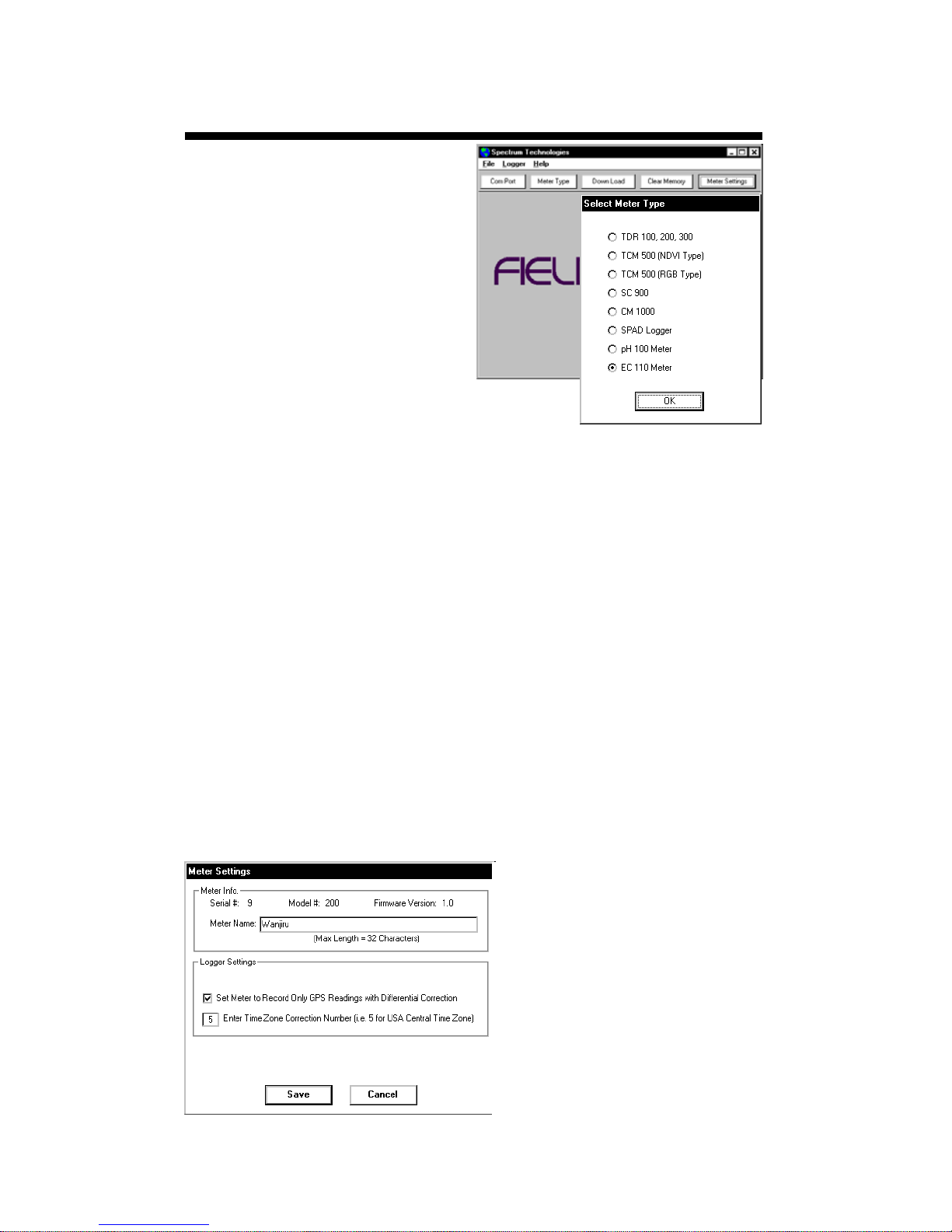
Meter Type
The Field Scout software
supports all of Spectrum
Technologies’ portable
data logging meters. Be
sure to select the EC
110 Meter from the Se-
lect Meter Type screen
Connecting to your Computer
To communicate with the data logger, connect the gray interface cable to the EC 110
meter’s RS-232 port. The port is located behind the
panel at the base of the meter (marked RS-232).
Open the software and turn on the meter so it is in
Communication mode (see Data Logger Operation,
p. 4). In order to communicate through your computer, the COM port connected to your serial port
must be selected. For most machines, this will be
COM 1. If you are having trouble connecting, try selecting another COM port. This can be done by
clicking the COM port toolbar button or by clicking
“Select Comm Port” from the File menu.
Meter Settings
Clicking on this button
will bring up the Meter
Settings screen. This
screen allows you to
configure the data log-
ger. The Meter Name
will be the title on the
first line of the
8
downloaded files.
Page 9

If the box below the logger name field is checked,
the logger will store GPS data only if it has been differentially corrected. If the differential correction is
not found, only the pH reading will be stored in the
data file. A time zone correction should be entered
in the last box.
Download
After clicking the Download button, a progress bar
will confirm that data is being extracted from the logger. When com-
pleted, the Save Data
As box will appear.
From here you can
give the data file a descriptive name and
select a folder in
which to save it. The folder selection field on the
right allows you to browse to any folder in your system.
When the file has been saved, the software will give
you the option of immediately viewing the file. The
data file is stored as a comma-delimited text file and
may be viewed in any text editor or spreadsheet software.
Clear Memory
Data is not automatically removed from the logger
memory after a download. The Clear Memory but-
ton clears all data from the memory.
9
Page 10
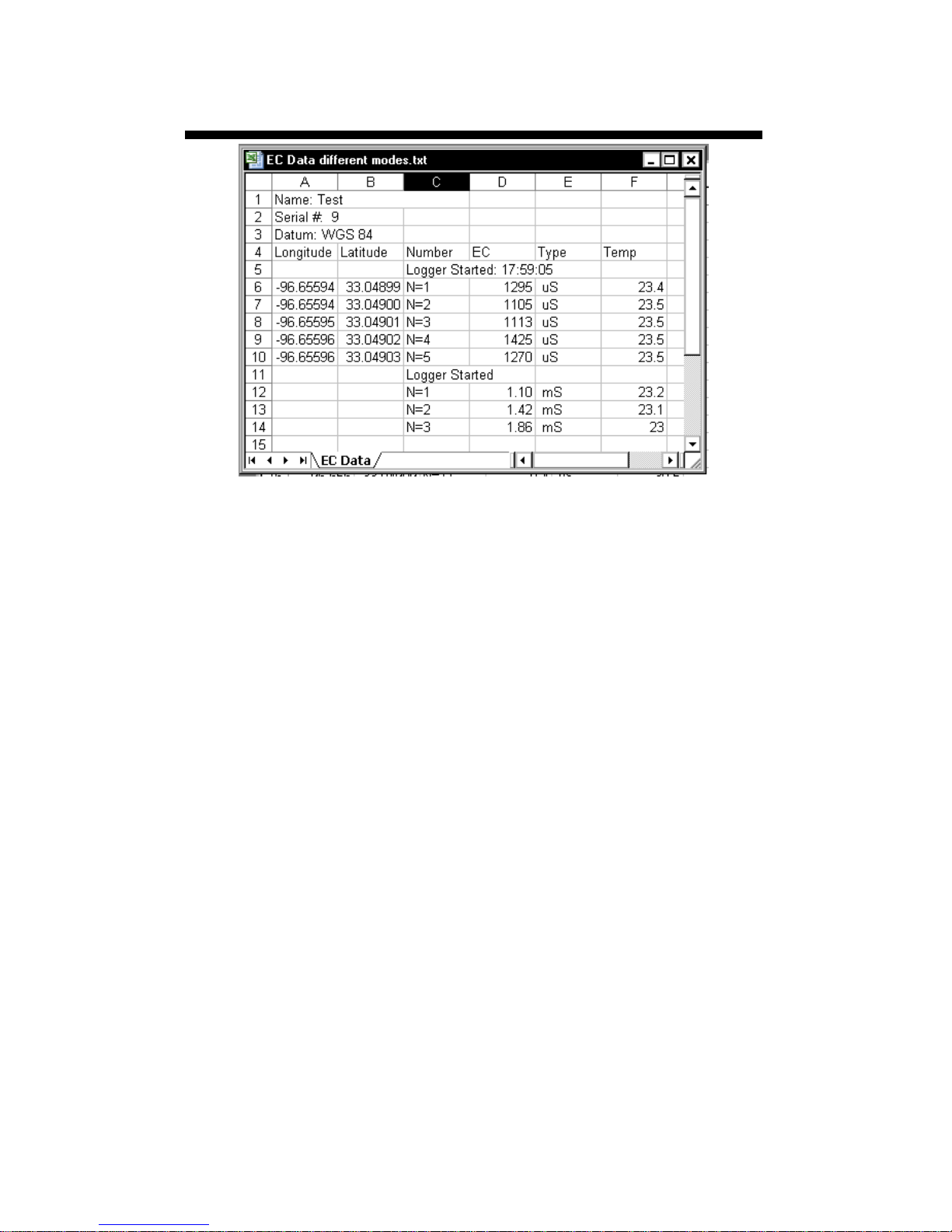
Data Files
Sample data showing results of data collected with and
without GPS activated. Note: GPS signal not found when
recording data in lines 12 through 14.
The data is stored in comma-delimited text files.
These files can be opened with text-editing software
(e.g. MicroSoft Word) or spreadsheet software (e.g.
Excel).
The first two lines of the data file give the logger’s
name and serial number. The third line indicates
that latitude and longitude are referenced to the 1984
World Geodetic Survey datum. The fourth line
shows the column headings for the rest of the data
file.
Logging sessions are started and completed by turning the meter on and off. The start of a logging session is indicated by the data line “Logger Started.” If
a GPS signal was found at the start of a logger session, a time stamp is included on the “Logger
Started” line.
10
Page 11

The data is separated into 6 fields: Latitude and Longitude (blank if a GPS unit was not connected), sample number, EC value, EC units, and temperature.
Possible measurement units for EC are μS/cm, mS/
cm or ppm. The units of temperature match what
has been selected on the meter.
Specifications
Measurement Capacity:
- 1,080 data points without GPS
- 648 data points with GPS
Operating Environment:
- Weather Resistant
Power:
- 4 x AAA batteries
- Provides 40 hours of logging
Software Requirements:
- Windows 95 or higher
- Field Scout Software v. 3.4 or higher
(included)
11
Page 12

GPS Connection
The data logger searches for a GPS signal when the
meter is powered up. If a signal is found, latitude
and longitude values will be added to the data file. If
a GPS signal is not found when powering up, the
meter will not search for it when taking readings. If
the meter is turned off and back on, it will again
search for the GPS signal. Be sure the meter is in
Measurement mode (see p. 4) before taking any
readings.
When taking a geo-referenced data measurement,
the LED will turn off while collecting the GPS signal.
The meter is again ready to take a reading when the
LED returns to a steady glow. If the datalogger
loses the GPS signal, the LED will flash briefly be-
fore returning to Measurement mode. In this case,
check the GPS battery status as well as the connec-
tion to the data logger.
GPS Settings
Your GPS unit should be set to NMEA 0183 input/
output messages. This standard requires your unit
be set to the following:
GGA data string
4800 baud rate
Timing - 1 second
8 data bits
No parity
1 stop bit
Tip: If you have your GPS unit set properly and
have checked the connection but still are not getting geo-referenced data, uncheck the box requiring the digital correction in Meter Settings
(pp. 8 - 9) .
12
Page 13
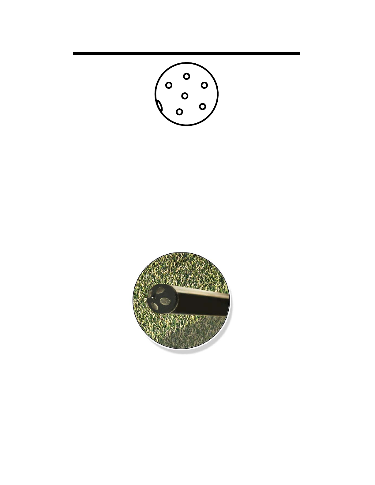
Direct- Insert Probe
Figure 4. Orientation of pins on probe/meter interface
Connecting the Probe
The female connector for the direct-insert probe
pushes straight onto the 6-pin male socket on the
digital reader (see fig. 4). When inserting the
probe, rotate the plug to align the notch on the
probe with the guide on the inner wall of the
socket. Secure the plug by rotating the locking
ring until it is snug.
Figure 5. Probe sensor tip
Probe Maintenance
The EC value measured by the sensor is highly
sensitive to surface contamination, especially from
skin oil. Therefore, the probe tip (see fig. 5)
should be cleaned regularly with rubbing alcohol
to ensure accurate conductivity measurements.
13
Page 14

Service and Support
In the unlikely event that you have a problem with
the hardware or software, please read the following.
Who do I contact?
Contact the company that you bought the
loggers from: Spectrum Technologies, Inc. or a
Spectrum Authorized Dealer.
Before calling, you can evaluate and often solve your
problem if you try the following.
1. Read this manual. It may only take a few moments
to get the answer you need.
2. Write down the events that led to the problem.
Have you changed anything in your computer
recently? Are you doing anything differently?
When Contacting Spectrum Technologies,
Inc.
Support. Be prepared to:
1. Provide details on the hardware and software
configuration of your computer including:
manufacturer, model number, peripherals, and
versions of the operating system.
2. Completely describe the problem. The more
information you provide, the faster and more
accurately we will be able to respond.
please indicate that you need Technical
14
Page 15

Warr anty
This product is warranted to be free from defects in material or
workmanship for one year from the date of purchase. During
the warranty period Spectrum will, at its option, either repair or
replace products that prove to be defective. This warranty does
not cover damage due to improper installation or use, lightning,
negligence, accident, or unauthorized modifications, or to incidental or consequential damages beyond the Spectrum product. Before returning a failed unit, you must obtain a Returned
Materials Authorization (RMA) from Spectrum. Spectrum is not
responsible for any package that is returned without a valid
RMA number or for the loss of the package by any shipping
company.
15
Page 16

This equipment has been manufactured for
Spectrum Technologies, Inc.
12360 S. Industrial Dr. East
Plainfield, IL 60585 USA
The Manufacturer’s DECLARATION OF CONFORMITY is on file at the above
address, and certifies conformity to the following:
Model Number: 2220
Description: Data Logging Electrical Conductivity Meter
Type: Electrical Equipment for Measurement, Control, and
Laboratory Use
Directive: 89/336/EEC
Standards: EN 61326 (1997)
EN 55022
EN 61000-4-2/-3
The meter also contains an add-on data logger that has been installed in other
products that have received CE certification.
Douglas L. Kieffer,
Soil/Water Products Manager March 4, 2009
(800) 248-8873 or (815) 436-4440
E-Mail: info@specmeters.com
16
12360 S. Industrial Dr. E
Plainfield IL 60585
Fax (815) 436-4460
www.specmeters.com
R 04/09
 Loading...