

Spectronics Spectroline DMXA Series, Spectroline DMHA Series Operator's Manual
OPERATOR’S MANUAL
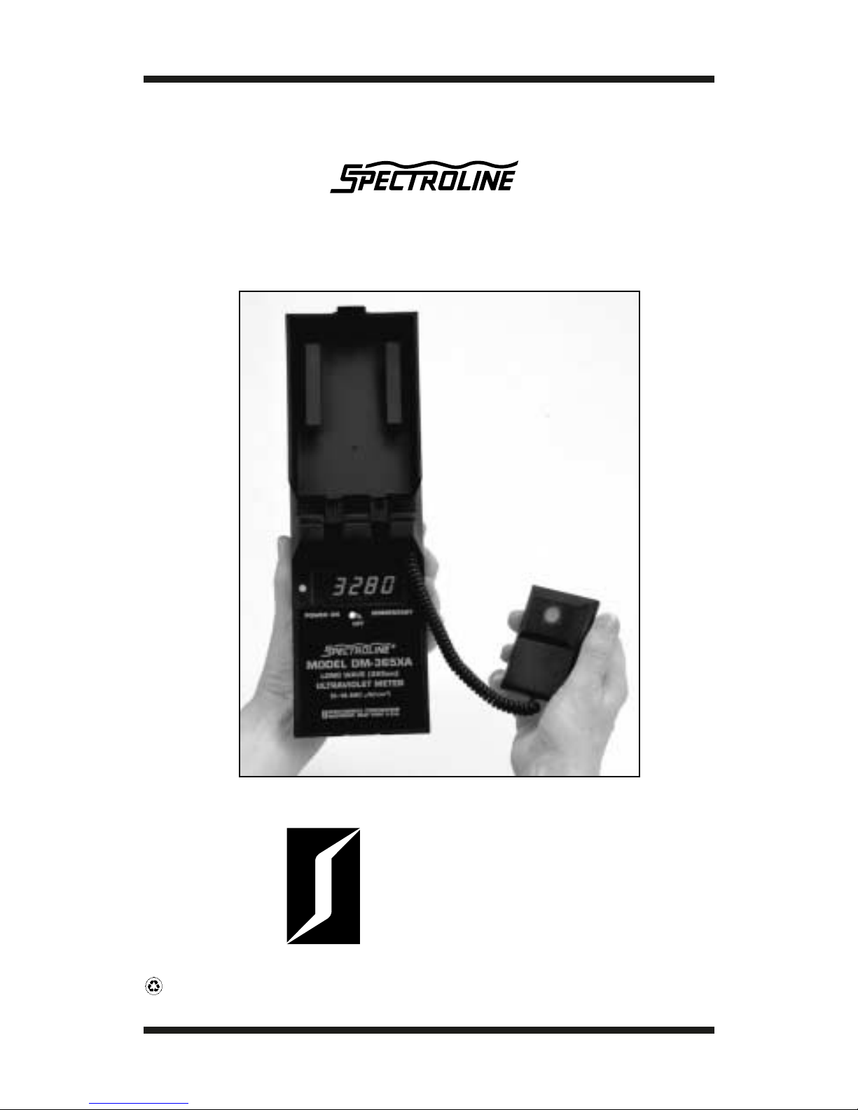
DMXA-Series and DMHA-Series
Digital Radiometers
®
SPECTRONICS
CORPORATION
956 Brush Hollow Road, P.O. Box 483
Westbury, New York 11590
800-274-8888 • 516-333-4840
Fax: 800
-491-6868 •
516
-333-4859
www.spectroline.com
Manual No. 84087-8
Printe d in U.S.A. Issue d: July 2004
Recycled
Paper

C on gr atulatio ns on ch o osin g a Sp e ctrolin e®DMXA-Seri es or DMH A-Seri es
digit al ra dio m et er.Sp e ctro nics C orporatio n h as d esi gne d it to pro vi d e
th e m ost d esir a ble f e atur es, the b est p erf or m anc e a n d, w h e n use d prop-
erly, ye ars of trouble -fr e e o p er a tion. Ple as e re a d th e instr u ctio ns in this
m anu a l c aref ul ly
b e f or e
usin g th e unit.
SECTION I INTRODUCTION
1.1 GENERAL
Th e Sp e ctro lin e DMX A-Series a n d D MH A-Series d ig it al ra d io me-
ters pro vi d e re a din gs fro m 0-19,990 µW / c m2or 0-199.9 m W / c m
2
(0-199,900 µW / cm2), resp e ctiv ely. Th e y f e atur e a n e asy-to-re a d LED
dis pl a y. Th eir ov er a ll a c cur a cy is b ett er th an ±5%.
Th ese r a dio met ers us e high-quality int erf er e n c e filt ers th a t exhi bit
a c c ur ate a nd c are fully c ontrolle d sp e ctr a l c o v er a g e, pr a ctic ally
elimin atin g un w a nt e d m e ter sensitivity to infrar e d interf er e n c e a nd
other un d esir a ble ra diatio ns. This a llo ws th e r e a din gs t o b e obt ain e d
dir e ctly inst e a d of b y c al c ul ation, a tim e-c onsu min g a nd errorpro ducin g proc edur e re quir e d b y c ert ain c om p etitiv e d evi c es. Th e
int erf ere n c e filt ers also minimiz e th e “sol ariz a tio n” eff e ct u p on th e
re sp onse of th e m e ters ov er tim e.
All Sp e ctrolin e r a dio met ers are c a librate d t o NIST st a n d ar ds b y p yro-
el e ctri c meth o ds for m axi mum a c cur a cy. Th ey ar e d esig n e d with a
lo w el e ctric a l imp e d a nc e , m akin g th eir lin e arity v astly su p erior to
th at of any other com p ar a bly pric e d r a dio meters. Th e se nsor h e a ds
are pro vid e d with a s p e ci al diff us er-sensor win d ow th at e nsur es
a c c ur ate La mb erti a n or C osin e r esp onse.
Th e m e t erin g ele ctro ni cs of th e DMXA-Series a n d D MHA-Series
ra diom ete rs f e atur e b ett er th a n ±5% a c c ura c y, inte gr ate d circ uitry,
a n d solid-st a t e LED dis pl a y. A d ditio n a l f e atur es of the ele ctro ni cs are
exc ellent te m p erature and ov er-r a n gin g c h ara c teristics. Th e DMXAS
eri es a n d D MH A-Seri es r a dio m et ers also h a v e built-in aut oz eroin g.
1.2 FE ATURES
1.2.1 Th e Sp e ctrolin e DMXA-Seri es and DMHA-Seri es digit a l r a dio me-
ters are po c ket-size d, b att ery-o p er ate d units suit a bl e for use in th e
m e asure m e nt of 254n m, 300n m, 365n m or 450n m w a v ele n gths.
1.2.2 Th e ra diom eters f e ature n o nr e char g e a ble a n d re c h arg e a bl e
o ptions. With th e no nre c h arg e a ble o ptio n, th e m et ers re q uire four
‘‘A A ’ ’ 1.5 v olt, a lk a lin e b att erie s. With the re c harg e a ble o ptio n,
th e m eters re q uire f our ‘‘ A A ’ ’ 1.25 volt, nic kel- c a d miu m b a tt eri es
a n d th e Sp e ctrolin e M od el D M-15 C 0001 b att ery ch arg er (se p arate ly
a v ail a bl e).
3

1.2.3 Th e r a di om e ters m e a s ur e irr a di a n c es as sp e cifi e d in Ta bl e 1-1.
Th e se nsor g en erate s e le c tri c al c urr ent pro p orti onal to th e irra dian c e
exp eri e n c e d a t a p l a n e d e fi n e d b y t h e f a c e of th e s e nsor.
A m plifi c ation a nd c urre nt-t o-volt a g e c on v ersio n circ uitry are c o nt ain ed within th e h a nd-h e ld displa y unit a n d its inte gr a te d n a ture
pro vi d es hi gh rel i a bility a nd a c c ur a cy in the re a din gs.
1.2.4 Th e nu m eric al displa y is a lig ht-e mittin g dio de (LED) f or pre cise
re a din g in ev e n to t al d arkn ess. Th e num er als are 0.5 in c h (12.7mm)
hig h and in a sin gl e p la n e f or dist a nt a nd wid e- a n gle vi e win g.
1.3 A C CESSORIES AND REPLA CEMENT PARTS
All a c c essori es a n d re pla c e m ent p arts re quir e d f or the op er a ti on of
th e r a dio meters are list e d in Ta bl e 7-1.
1.4 TECHNIC AL DATA
Ta ble 1-1 lists all the te c hnic al sp e cifi c atio ns f or the r a di o m e ters.
SECTION II INSTALLATION
2.1 UNPACKING AND INSPECTIO N
2.1.1 Un p a ck a nd insp e ct th e ra dio m et er for p ossi bl e d a m a g e in
ship m ent. Ch e ck th e p erform a n c e as soon as p ossi bl e. If d a m a g e is
not e d, n otify th e c arrier a nd su p plier b e fore usin g th e instru m ent.
Also c h e ck that all it e ms are in c lu d ed.
2.1.2Sa v e th e ship pin g c arton a n d p a ckin g m a teri als f or f uture
storin g or shi p pin g of the r a di o m e ter.
2.2 POWER SOURCE REQUIREMENTS
Th e ra d io meter is b a tt ery o p era te d. Th e b a tt eri es a re f a ct ory
inst a ll e d in the instru m ent.
WARNING
This r a dio mete r is c are fully d esig n e d t o pre v e nt a c cid e nt al sh o ck to
th e op er a tor wh en pro p erly use d. H o w e ve r, no en gin e erin g desi gn
c an re nd er sa f e a n instru m ent w hich is use d c arel essly. Th ere for e,
re c o m m end a tio ns presente d in this m a nu al must b e re a d c arefully
a n d th orou g hly und erstood b e fore any m e asure m ents are m a d e.
Failure to follow dire ctions could result in serious adverse effe cts.
Also, c ert ain m o d els ar e d esign e d f or use in r e gions of th e sp e ctrum,
not a bly th e ultr a viole t r a ng e, whi c h m a y be haz a rd ous to th e e y es
a n d / or skin of in divi du als. Ultr a violet pro te ctiv e e ye w e ar (UVS-30
sp e c t a cl es or UV G -50 go g gles) a nd f a c e we ar (UVF-80 f a c e shi el d)
are o bt a in a bl e fro m Sp e ctro nics C orp or a tio n.
4

2.3 INSTALLATION
Th e r a di om e ter m ay b e o p er ate d in a ny p ositio n with o ut c om pro-
mising a c c ur a cy. Th e se nsor pro b e m ay a lso b e position e d at a ny
a n gl e.
TABLE 1-1 TECHNIC AL DATA
1. Re adout Unit
Irra dia nc e Ra n g e
DMXA-Seri es . . . . . . . . . . . . . . . . . . . . . . . . . . . . . . . 0-19,990 µW / c m
2
DMH A-Seri es . . . . . . . . . . . . . . 0-199.9 mW /c m2(0-199,900 µW / cm2)
R
eso lutio n
DMXA-Seri es. . . . . . . . . . . . . . . . . . . . . . . . . . . . . . . . . . . . 10 µW / cm
2
DMH A-Seri es. . . . . . . . . . . . . . . . . . . . . . . 0.1 m W/ c m2(100 µ W /c m2)
Disp lay
DMXA-Seri es. . . . . . . . . . . . . . . . . . . . . . . . . 4
1
⁄2di git, 7 se g m e nt, LED
0.5 in c h (12.7m m) high
DMH A-Seri es . . . . . . . . . . . . . . . . . . . . . . . . 3
1
⁄2di git, 7 se g m e nt, LED
0.5 in c h (12.7m m) high
C onversion Ra te . . . . . . . . . . . . . . . . . 3 r e a din gs p er se c on d nomin a l
O v era ll Ac c ur a cy . . . . . . . . . . . . . . . . . . . . . . . . . . . . . B ett er th a n ±5%
with ref er e n c e to NIST st a nd ards
Te m p er a ture C o e ffi ci e nt . . . . . . . . . . . . . . . . . ±0.025%/° C (0 t o 50° C )
2. Sensor
S
p e ctral Ra n g es
DM-254X A, DM-254H A . . . . . . . . . . . . . . . 230-280 n a n o m et ers (nm)
DM-300X A, DM-300H A . . . . . . . . . . . . . . . 280-320 n a n o m et ers (nm)
DM-365X A, DM-365H A . . . . . . . . . . . . . . . 320-400 n a n o m et ers (nm)
DM-450X A, DM-450H A . . . . . . . . . . . . . . . 420-480 n a n o m et ers (nm)
Te m p er a ture C o e ffici e nt . . . . . . . . . . . . . . . . . . ±0.20% /° C (0 t o 50° C )
3. Power Requirem ents
Batt ery O p eratio n
Fo ur no nre charg e a ble ‘ ‘ A A ’’ siz e alk alin e b attery c ells ar e in clu d e d
as st a n d ard.
Fo ur re c h arg e a ble ‘‘ A A’’ size nic a d b att ery c ells a n d a b a tt ery
re c h arg er are a v a il a bl e as an o ptio n.
4. Reference Conditions . . . . . . Sp e cifi e d on C ertific at e of C a libratio n.
5. Dim ensions
R
e a d out Unit
L
e n gth . . . . 7.25 in (18.4c m) Width . . . . . . . 3.50 in (8.9 c m)
Thic kn ess. . . . . . 2 in (5.1c m) Weight . . . . . . . . 1 lb (0.45kg)
S
e nsor
L
e ngth . . . . . . . . 3 in (7.6 c m) Wid th . . . . . . . . . . 2 in (5.1 c m)
Thic kn ess . . . . 0.70 in (1.8 c m) We ig ht . . . . . . .
1.25 oz (35.4g)
S
e nsor C or d Le ngth . . . . . . . . . . . . . . . . . . . . . . . . . . . . . . . . 2 ft (0.6m)
5

SECTION III C ONTROLS, C O NNECTORS AND INDIC ATORS
3.1 GENERAL
All o p er a ting c ontrols, c on n e ct ors a n d in di c ators are d esc rib e d in
Ta ble 3-1. Be c o m e f a mili a r with e a ch it e m prior to op era tin g th e
ra dio m et er for th e first tim e.
TABLE 3-1 FRO NT AND B A CK PANEL DESCRIPTION
1. Pow er Swit c h: With th e du al-o p er atio n to g gl e swit c h flip p ed to
th e ‘ ‘P O WER O N’’ position, th e ra diom e ter will
re m a in a ctiv at e d u ntil m a nu a lly turn ed off. Th e
m e t er will also o p er a t e wh e n the switch is held in
th e ‘‘ M O MENT ARY’ ’ p osition, b ut the swit c h will
a ut o m ati c ally r eturn to th e ‘ ‘ OFF ’’ p os itio n onc e
pressure is rel e ase d.
2. Nu m eric al Displ a y: Th e digit al displa y uses LEDs a nd in clu des a ‘‘1 ’’
di git a nd 7-s e gm ent ty p e 0-9 digits. Th e l ast digit is
p er m anently s et a t ‘ ‘0.’ ’ O v er-ra ng e (or out-of-
rang e) c onditi on is in di c ate d by a bl a nk displ a y,
exc e p t f or the m ost si gnific a nt ‘‘ 1. ’’
3. Retra ct a bl e C ord: This c oil cord c onne c ts th e se nsor t o th e re a d out
unit.
4. Ch arg er Ja ck: Use o nly with re ch arg e a ble b att ery c ells. A ny
other typ e of c ell m a y pro du c e h az a rd ous c o n di-
tions a n d m a y d a m a g e th e instrum e nt.
5. Se nsor Win d ow :
S
a pphire d iffus er t o ensur e g o o d c osin e resp ons e.
6. B a ttery Le v el Whe n light e d, gr e en LED in di c ates th a t b att ery
In di c ator Lig ht l e v el is a d e qu ate .
(N ot Illustr a te d)
6
 Loading...