

Page 1

OPERATOR’S MANUAL
DMXA-Series and DMHA-Series
Digital Radiometers
®
Manual No. 84087-8
Printed in U.S.A. Issued: July 2004
Recycled
Paper
www.GlobalTestSupply.com
Page 2

Congratulations on choosing a Spectroline®DMXA-Series or DMHA-Series
digital radiometer. Spectronics Corporation has designed it to provide
the most desirable features, the best performance and, when used properly, years of trouble-free operation. Please read the instructions in this
manual carefully before using the unit.
SECTION I INTRODUCTION
1.1 GENERAL
The Spectroline DMXA-Series and DMHA-Series digital radiometers provide readings from 0-19,990 µW/cm
2
or 0-199.9 mW/cm
2
(0-199,900 µW/cm2), respectively. They feature an easy-to-read LED
display. Their overall accuracy is better than ±5%.
These radiometers use high-quality interference filters that exhibit
accurate and carefully controlled spectral coverage, practically
eliminating unwanted meter sensitivity to infrared interference and
other undesirable radiations. This allows the readings to be obtained
directly instead of by calculation, a time-consuming and errorproducing procedure required by certain competitive devices. The
interference filters also minimize the “solarization” effect upon the
response of the meters over time.
All Spectroline radiometers are calibrated to NIST standards by pyroelectric methods for maximum accuracy. They are designed with a
low electrical impedance, making their linearity vastly superior to
that of any other comparably priced radiometers. The sensor heads
are provided with a special diffuser-sensor window that ensures
accurate Lambertian or Cosine response.
The metering electronics of the DMXA-Series and DMHA-Series
radiometers feature better than ±5% accuracy, integrated circuitry,
and solid-state LED display. Additional features of the electronics are
excellent temperature and over-ranging characteristics. The DMXASeries and DMHA-Series radiometers also have built-in autozeroing.
1.2 FEATURES
1.2.1 The Spectroline DMXA-Series and DMHA-Series digital radiome-
ters are pocket-sized, battery-operated units suitable for use in the
measurement of 254nm, 300nm, 365nm or 450nm wavelengths.
1.2.2 The radiometers feature nonrechargeable and rechargeable
options. With the nonrechargeable option, the meters require four
‘‘AA’’ 1.5 volt, alkaline batteries. With the rechargeable option,
the meters require four ‘‘AA’’ 1.25 volt, nickel-cadmium batteries
and the Spectroline Model DM-15C0001 battery charger (separately
available).
3
www.GlobalTestSupply.com
Page 3

1.2.3 The radiometers measure irradiances as specified in Table 1-1.
The sensor generates electrical current proportional to the irradiance
experienced at a plane defined by the face of the sensor.
Amplification and current-to-voltage conversion circuitry are contained within the hand-held display unit and its integrated nature
provides high reliability and accuracy in the readings.
1.2.4 The numerical display is a light-emitting diode (LED) for precise
reading in even total darkness. The numerals are 0.5 inch (12.7mm)
high and in a single plane for distant and wide-angle viewing.
1.3 ACCESSORIES AND REPLACEMENT PAR TS
All accessories and replacement parts required for the operation of
the radiometers are listed in Table 7-1.
1.4 TECHNICAL DATA
Table 1-1 lists all the technical specifications for the radiometers.
SECTION II INSTALLATION
2.1 UNPACKING AND INSPECTION
2.1.1 Unpack and inspect the radiometer for possible damage in
shipment. Check the perfor mance as soon as possible. If damage is
noted, notify the carrier and supplier before using the instrument.
Also check that all items are included.
2.1.2 Save the shipping carton and packing materials for future
storing or shipping of the radiometer.
2.2 POWER SOURCE REQUIREMENTS
The radiometer is battery operated. The batteries are factory
installed in the instrument.
WARNING
This radiometer is carefully designed to prevent accidental shock to
the operator when properly used. However, no engineering design
can render safe an instrument which is used carelessly. Therefore,
recommendations presented in this manual must be read carefully
and thoroughly understood before any measurements are made.
Failure to follow directions could result in serious adverse effects.
Also, certain models are designed for use in regions of the spectrum,
notably the ultraviolet range, which may be hazardous to the eyes
and/or skin of individuals. Ultraviolet protective eyewear (UVS-30
spectacles or UVG-50 goggles) and facewear (UVF-80 face shield)
are obtainable from Spectronics Corporation.
4
www.GlobalTestSupply.com
Page 4

2.3 INSTALLATION
The radiometer may be operated in any position without compromising accuracy. The sensor probe may also be positioned at any
angle.
TABLE 1-1 TECHNICAL DATA
1.Readout Unit
Irradiance Range
DMXA-Series. . . . . . . . . . . . . . . . . . . . . . . . . . . . . . . 0-19,990 µW/cm
2
DMHA-Series . . . . . . . . . . . . . . 0-199.9 mW/cm2(0-199,900 µW/cm2)
Resolution
DMXA-Series. . . . . . . . . . . . . . . . . . . . . . . . . . . . . . . . . . . . 10 µW/cm
2
DMHA-Series. . . . . . . . . . . . . . . . . . . . . . . 0.1 mW/cm2(100 µW/cm2)
Display
DMXA-Series. . . . . . . . . . . . . . . . . . . . . . . . . 4
1
⁄2digit, 7 segment, LED
0.5 inch (12.7mm) high
DMHA-Series . . . . . . . . . . . . . . . . . . . . . . . . 3
1
⁄2digit, 7 segment, LED
0.5 inch (12.7mm) high
Conversion Rate. . . . . . . . . . . . . . . . . 3 readings per second nominal
Overall Accuracy. . . . . . . . . . . . . . . . . . . . . . . . . . . . . Better than ±5%
with reference to NIST standards
Temperature Coefficient . . . . . . . . . . . . . . . . . ±0.025%/°C (0 to 50°C)
2.Sensor
Spectral Ranges
DM-254XA, DM-254HA . . . . . . . . . . . . . . . 230-280 nanometers (nm)
DM-300XA, DM-300HA . . . . . . . . . . . . . . . 280-320 nanometers (nm)
DM-365XA, DM-365HA . . . . . . . . . . . . . . . 320-400 nanometers (nm)
DM-450XA, DM-450HA . . . . . . . . . . . . . . . 420-480 nanometers (nm)
Temperature Coefficient . . . . . . . . . . . . . . . . . . ±0.20%/°C (0 to 50°C)
3.Power Requirements
Battery Operation
Four nonrechargeable ‘‘AA’’ size alkaline battery cells are included
as standard.
Four rechargeable ‘‘AA’’ size nicad battery cells and a battery
recharger are available as an option.
4.Reference Conditions . . . . . . Specified on Certificate of Calibration.
5.Dimensions
Readout Unit
Length . . . . 7.25 in (18.4cm) Width . . . . . . . 3.50 in (8.9cm)
Thickness. . . . . . 2 in (5.1cm) Weight . . . . . . . . 1 lb (0.45kg)
Sensor
Length . . . . . . . . 3 in (7.6cm) Width . . . . . . . . . . 2 in (5.1cm)
Thickness. . . . 0.70 in (1.8cm) Weight . . . . . . .
1.25 oz (35.4g)
Sensor Cord Length. . . . . . . . . . . . . . . . . . . . . . . . . . . . . . . . 2 ft (0.6m)
5
www.GlobalTestSupply.com
Page 5

SECTION III CONTROLS, CONNECTORS AND INDICATORS
3.1 GENERAL
All operating controls, connectors and indicators are described in
Table 3-1. Become familiar with each item prior to operating the
radiometer for the first time.
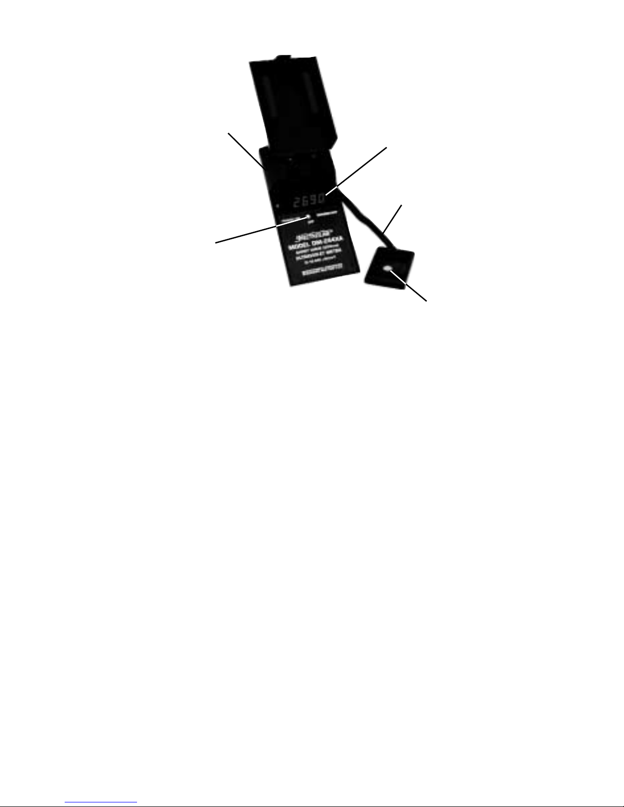
TABLE 3-1 FRONT AND BACK PANEL DESCRIPTION
1. Power Switch: With the dual-operation toggle switch flipped to
the ‘‘POWER ON’’ position, the radiometer will
remain activated until manually turned off. The
meter will also operate when the switch is held in
the ‘‘MOMENTARY’’ position, but the switch will
automatically return to the ‘‘OFF’’ position once
pressure is released.
2. Numerical Display: The digital display uses LEDs and includes a ‘‘1’’
digit and 7-segment type 0-9 digits. The last digit is
permanently set at ‘‘0.’’ Over-range (or out-ofrange) condition is indicated by a blank display,
except for the most significant ‘‘1.’’
3. Retractable Cord: This coil cord connects the sensor to the readout
unit.
4. Charger Jack: Use only with rechargeable battery cells. Any
other type of cell may produce hazardous conditions and may damage the instrument.
5. Sensor Window: Sapphire diffuser to ensure good cosine response.
6. Battery Level When lighted, green LED indicates that battery
Indicator Light level is adequate.
(Not Illustrated)
6
www.GlobalTestSupply.com
Page 6
SECTION IV OPERATION
4.1 GENERAL
This section of the manual contains information required to use and
operate the radiometer in a safe and proper manner.
4.2 IRRADIANCE MEASUREMENT PROCEDURE
a. Be sure that this meter is appropriate for the spectral region of
interest.
b. Place the sensor at the point where the irradiance is to be mea-
sured.
c. Turn on the light source.
d. Flip the power switch to the ‘‘POWER ON’’ or ‘‘MOMENTARY’’ posi-
tion as desired.
e. The value of the irradiance over the sensitive area of the sensor will
be displayed in microwatts per square centimeter (DMXA-Series)
or milliwatts per square centimeter (DMHA-Series).
f. Return the power switch to the “OFF” position and remove the
sensor from the light source.
NOTES: The least significant digits of the measured irradiance may
change as the display is being observed. The amount of variance will
depend on the stability of the light source, with the change being
smaller for tubular fluorescent-type lamps and larger for HID (High
Intensity Discharge) lamps.
7
1. Power Switch
2. Numerical Display
5. Sensor Window
3. Retractable Cord
4. Charger Jack
(Back of Instrument)
www.GlobalTestSupply.com
Page 7
Also, interference filters are not perfect band-pass filters. Therefore, if an
inappropriate measurement is attempted (for example, measurement of
small amounts of UV-B from an intense UV-A radiation source or measurement of relatively small amounts of UV-A, UV-B or UV-C in sunlight),
errors can be expected if appropriate corrections are not made.
4.2.1 REMOTE USE OF THE SENSOR
To Remove Sensor: First, release cord from retaining slot. Then slide
sensor out. Do not pull out sensor without first
releasing cord, to avoid stretching of cord.
To Replace Sensor: Slide sensor up into receptacle with cord down
and filter up. Wrap cord clockwise around
retaining slot. See diagram inside front cover of
radiometer.
SECTION V THEORY OF OPERATION
5.1 OVERALL SYSTEM
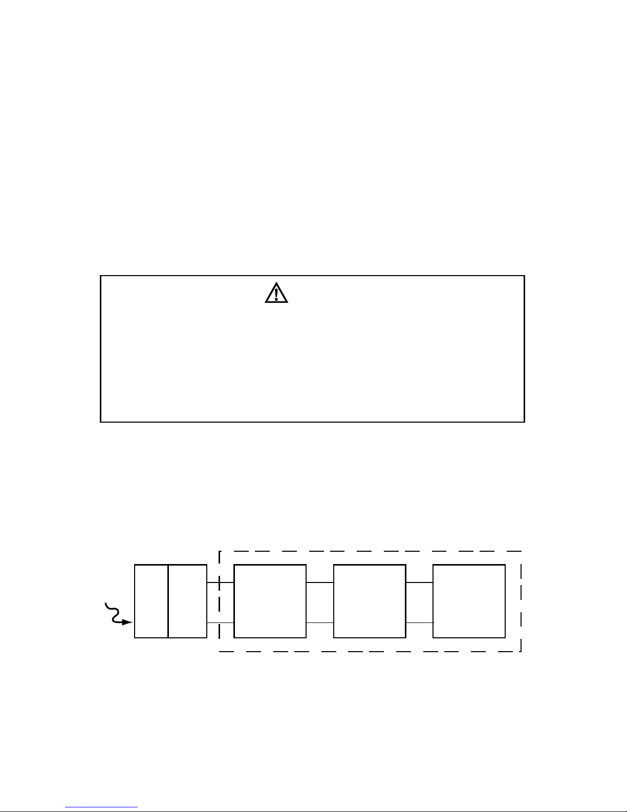
The basic block diagram for the radiometer is shown in Figure 5-1.
Figure 5-1 Basic System Block Diagram
5.1.1 THE INPUT OPTICS
The Lambertian (Cosine) response of the sensor head is desirable for
many measurement applications, especially those where the angle
from the source to the detector is variable or those situations where
OPTICAL
STACK
DETECTOR
CURRENT TO
VOLTAGE
CONVERSION
LSI
ANALOG TO
DIGITAL
CONVERSION
NUMERICAL
DISPLAY
SENSOR
RADIOMETER
LIGHT
CAUTION
This radiometer is designed for intermittent use only. Do not
leave the exposed sensor head under the light source any longer
than necessary to take measurements. Prolonged exposure
can result in premature aging and/or solarization of the sensor,
necessitating more frequent recalibration to maintain accurate
readings. In time, such exposure can cause permanent damage to
the sensor.
8
www.GlobalTestSupply.com
Page 8

the angle from the source is ‘‘extended,’’ such as in the measurement of a fluorescent lamp at distances comparable to or shorter
than its length. In the latter case, the extended source provides radiation from many angles, all of which must be properly ‘‘weighted’’
as to their effectiveness on the plane represented by the sensor
surface.
In actual practice, it is difficult to make a sensor conform to the ideal
response over the entire solid angle of 2π steradians. The sensor
heads provided with the DMXA-Series and DMHA-Series radiometers
minimize this problem by using a diffusing material (sapphire) having
excellent transmission at the various spectral regions, which is mountedclose to the surface of the sensor so that the oblique rays are not
obstructed. The spectral range is selected by providing an appropriate optical interference filter before the sensor cell assembly.
5.1.2 THE SENSOR CELL
Photovoltaic Operation
When a p-n junction is operated with no externally applied voltage,
it is considered to be operating in the photovoltaic mode. Under this
zero applied voltage condition and low levels of incident light, the
p-n junction will generate a current proportional to the light power
incident on the active surface. This photon induced current, or
photo-current, will divide between the diode parallel dynamic resistance and the parallel load resistance. The dynamic resistance is
normally a high value and is an inverse exponential function of forward voltage. The direction of current flow will produce a voltage
across the diode that opposes the band-gap potential of the photodiode junction, thus forward biasing it. As a result, the value of the
diode dynamic resistance (Rd) drops exponentially as the irradiance
increases and the photogenerated voltage is a quasi-logarithmic
function of diode irradiance when the external load resistance is
considered. Another major disadvantage is that Rdtypically has a
wide spread of values over different production batches.
One way of achieving sufficiently low load resistance and eliminating the effect of the diode parallel resistance is to feed the photocurrent into the virtual ground of an operational amplifier.
The output voltage is the result of the photocurrent being driven by
the amplifier through the feedback resistor and the input impedance
R in=Rf/A where A is the open loop gain and Rfthe feedback
resistor.
This circuit has a linear response and is low noise due to the almost
complete elimination of leakage current with the zero bias. This
results in a proportional voltage being presented to the signal conditioning section of the electronics.
9
www.GlobalTestSupply.com
Page 9
5.1.3 ANALOG TO DIGITAL CONVERTER SECTION
The analog-to-digital converter uses a large-scale integrated (LSI)
circuit and changes the DC voltage into digital information. This
digital information is decoded into 7-segment information for the LED
display.
5.1.4 DISPLAY
The DMXA-Series radiometers feature a 4
1
⁄2 digit LED display that
reads directly in microwatts per square centimeter (µW/cm
2
), while
the DMHA-Series feature a 3
1
⁄2 digit LED display that reads directly in
milliwatts per square centimeter (mW/cm
2
).
SECTION VI OPERATOR SERVICING
6.1 GENERAL
The radiometer is carefully designed and constructed with high quality
components. By providing reasonable care and following the
instructions in this manual, the user can expect a long, useful service
life from the instrument.
6.2 WARRANTY
The warranty policy for the DMXA-Series and DMHA-Series radiometers is provided on the Certificate of Limited Warranty enclosed separately with each unit.
NOTE: For assistance of any kind, contact the Customer Service
Department at Spectronics Corporation. In the U.S. and Canada,
call toll-free 1-800-274-8888. Give full details of the difficulty and
include the model and serial numbers of the unit and the date of
purchase. If return of the radiometer to the factory is deemed necessary, shipping instructions will be provided. If an estimate of
charges for nonwarranty work or other service work is required, a
quote will be furnished upon evaluation of the unit. Service work will
not be perfor med without customer approval.
WARNING
The following operator servicing instructions are intended to be used
by qualified personnel for limited maintenance of the radiometer.
Do not perform any servicing other than that contained in these
operator instructions. Return the unit to the factory for other main-
tenance not covered in this section.
10
www.GlobalTestSupply.com
Page 10
6.3 SHIPPING
Carefully pack the radiometer in the original shipping container and
packing materials. Ship it prepaid to the factory and be sure to insure
the unit for full value.
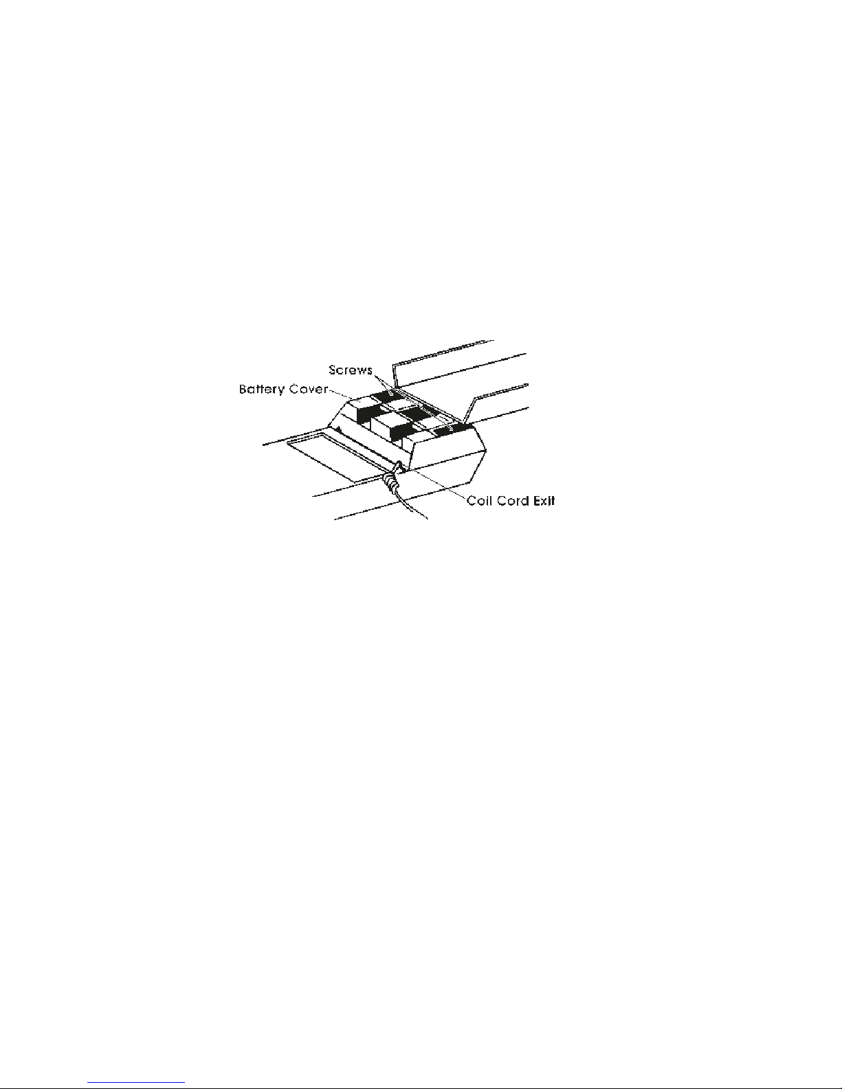
6.4 BATTERY COVER REMOVAL
The battery cover at the back of the radiometer can be removed for
maintenance purposes by the following procedure:
a. Disconnect the charger (if used) from the unit.
b. Turn the two screws in the battery cover counterclockwise until the
cover is removed.
c. Reverse this procedure when replacing the cover.
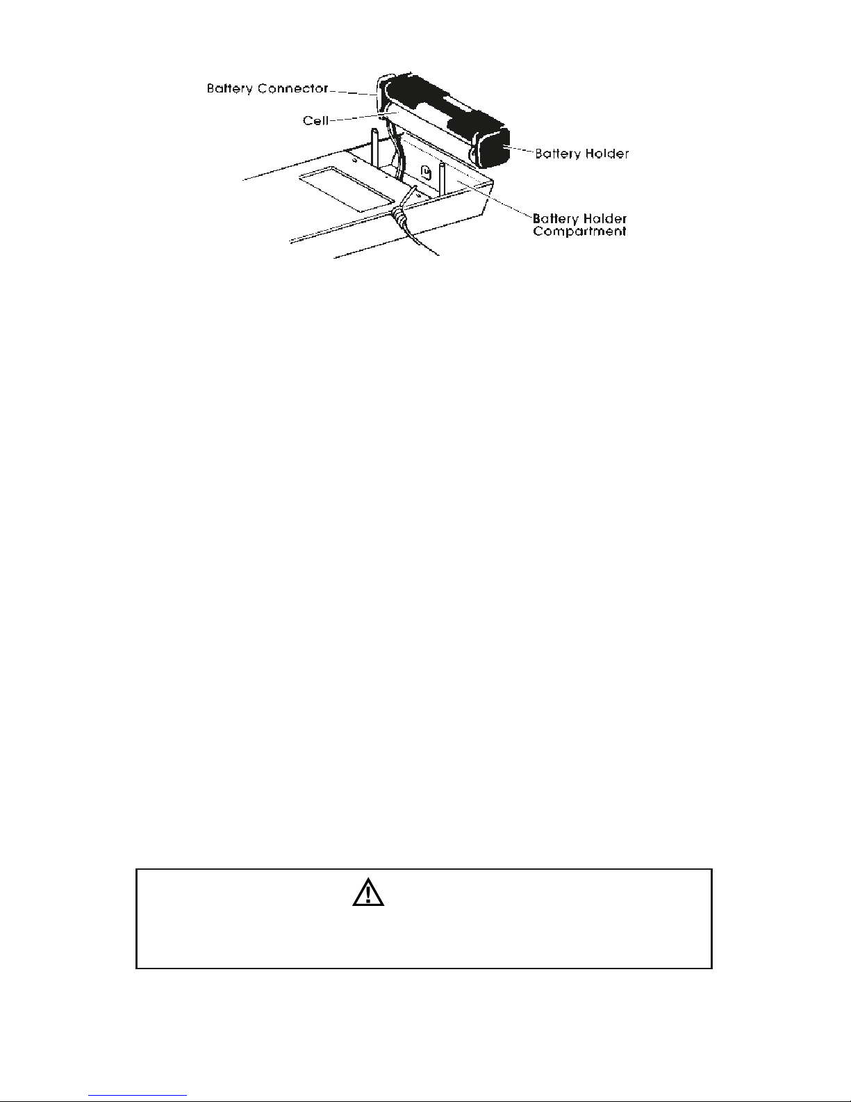
6.5 BATTERY INSTALLATION AND REPLACEMENT
The radiometer is provided with nonrechargeable, ‘‘AA’’ size alkaline cells as standard. If rechargeable nickel-cadmium batteries are
used, the Spectroline DM-15C0001 bivoltage AC recharger must be
used. Use of any other charger may damage the meter. Refer to the
markings on the DM-15C0001 for power source requirements.
Battery cells should be replaced as follows:
a. Lift out the battery holder from the radiometer and remove the
holder from the battery connector.
b. Take out the old cells from the holder.
c. Insert four new cells, ensuring that the cells are installed according
to the polarity designated on the battery holder. FAILURE TO DO
SO CAN DAMAGE THE RADIOMETER.
d. Check that the battery holder contacts are clean and making
good connection.
e. Reconnect the battery holder to the battery connector.
f. Replace the battery holder in its compartment and replace the
battery cover ensuring that the coil cord exits in the appropriate
slot.
11
www.GlobalTestSupply.com
Page 11
6.6 BATTERY CHARGING
Nickel-cadmium batteries should be recharged as follows:
a. Be sure the radiometer is turned off.
b. Plug the jack of the DM-15C0001 recharger into the receptacle at
the back of the radiometer.
c. Set the recharger at the proper voltage and plug it into an appro-
priate AC power source.
d. Approximately 12 hours are required to fully charge the batteries.
6.7 RECHARGEABLE BATTERY CARE
a. Avoid discharging rechargeable batteries completely or leaving
discharged cells in the radiometer for long periods of time.
b. Ensure that all newly purchased rechargeable cells are charged
for at least 15 minutes before operating the radiometer.
6.8 PREVENTIVE MAINTENANCE
6.8.1 Daily Care
a. Immediately clean all spilled materials from the radiometer and
wipe dry. If necessary, moisten a cloth with soap and water to
clean plastic surfaces and the sensor head. The sensor surface
should be rinsed with ethanol to remove any residual soap and/or
organic contaminants.
b. Whenever possible, avoid exposure or usage in areas that are
subject to temperature and humidity extremes, vibration or
mechanical shock, dust or corrosive fumes, or strong electrical or
electromagnetic interference.
WARNING
Do not attempt to clean this instrument when it is connected to the
charger.
12
www.GlobalTestSupply.com
Page 12

6.8.2 Monthly Care
Verify unit calibration by performing operational checks using known
value sources. If the need for recalibration is indicated, contact the
factory.
6.8.3 Semiannual or Annual Care
It is recommended that the radiometer be returned to the factory for
a complete overall check and recalibration. Return long wave units
(365nm) at least every 12 months. All others should be returned at
least every 6 months. Contact the Customer Services Department for
shipping instructions before returning the unit. In the U.S. and
Canada, call 1-800-274-8888.
6.8.4 Storage
When the radiometer is not in use, store it in a location free from temperature extremes, dust or corrosive fumes, and vibration or
mechanical shock.
6.9 TROUBLESHOOTING
6.9.1 If the radiometer does not yield satisfactory results, follow this
procedure before attempting to service the unit:
a. Review and comply with the Irradiance Measurement Procedure,
listed in paragraph 4.2.
b. Check that the irradiance intensity range being measured is with-
in the rating of the unit.
c. Be sure that the batteries are properly installed (refer to paragraph
6.5) and that they are charged.
d. Ensure that the environment in which the radiometer is being used
is within the unit specifications.
e. Inspect the sensor head and readout unit for visible damage. If
any damage is observed, the radiometer should be returned to
the factory. Be sure to contact the Customer Service Department
at Spectronics Corporation for shipping instructions before return-
ing the radiometer . In the U.S. and Canada, call toll-free 1-800-274-
8888. A quote will be furnished upon receipt and evaluation of the
unit. Out-of-warranty service work will not be perfor med without
customer approval.
NOTE
The calibration potentiometer is located inside the radiometer. Do
not attempt to recalibrate this unit. Spectronics Corporation does
not guarantee the readings if the meter has been calibrated by any
other facility.
13
www.GlobalTestSupply.com
Page 13

14
6.9.2 If the steps taken in paragraph 6.9.1 do not yield satisfaction, refer
to the Troubleshooting Chart (Table 6-1). Direct all other repair and
adjustment needs to the factory.
TABLE 6-1 TROUBLESHOOTING CHART
Symptom Probable Cause Cure
1. Low intensity on
numerical display.
Batteries not fully
charged, defective or
making poor contact.
Remove battery cover
and check that batteries are making good
contact. Refer to 6.5. If
good contact is made
check the voltage. If
symptom persists
replace batteries.
2. No numerical
display.
a. Batteries not
installed.
a. Remove battery
cover to ascertain
whether batteries
are present.
b. Batteries installed
incorrectly.
b. Remove batteries
and check that
polarity is correct.
c. Batteries not
making contact.
c. Ensure that good
contact is made.
Check voltage. If
symptom persists
replace batteries.
d. Batteries not
charged.
d. Recharge nicad
batteries or replace
alkaline batteries.
www.GlobalTestSupply.com
Page 14
15
SECTION VII ORDERING INFORMATION
ACCESSORY
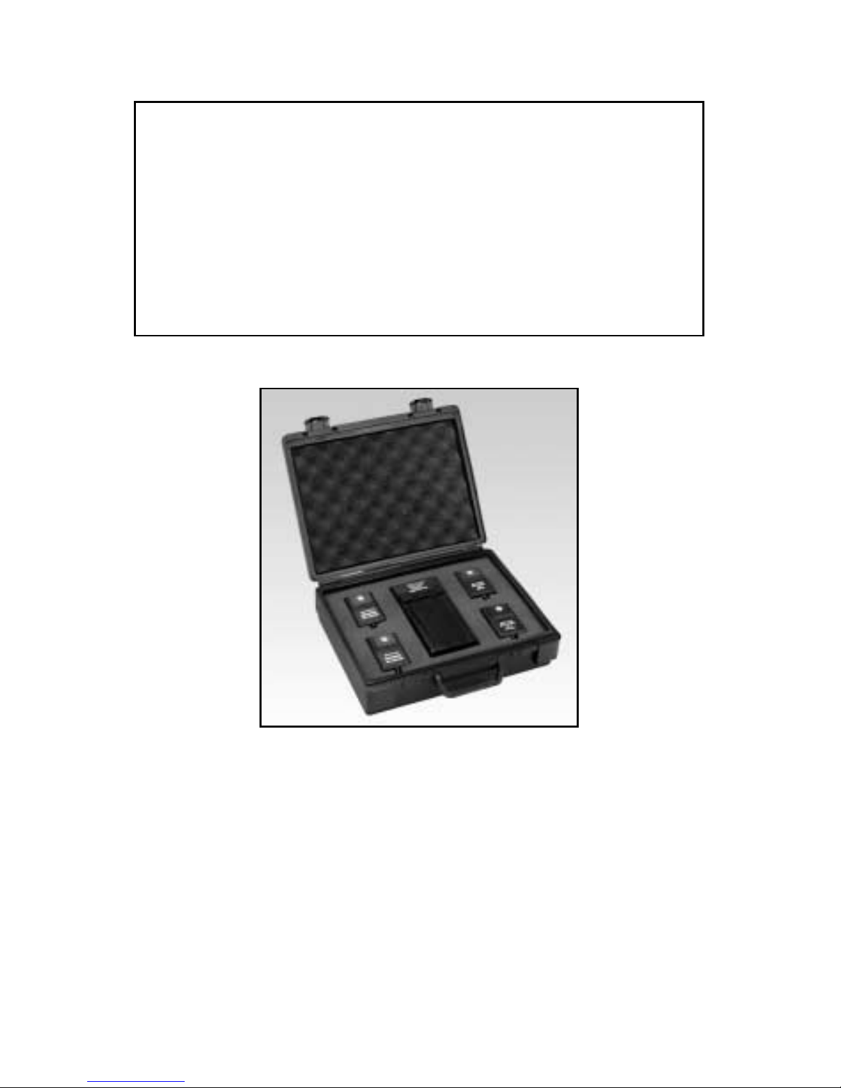
DR-75 Carrying Case
TABLE 7-1
Description Part No.
BATTERY, Alkaline, ‘‘AA’’ Size, 1.5 Volt . . . . . . . . . . . . . Commercial
(Four Required)
BATTERY, Nicad Rechargeable, ‘‘AA’’ Size, . . . . . . . . . . . . . DM-N4
1.25 Volt (Four Required)
BATTERY RECHARGER, Bivoltage . . . . . . . . . . . . . . . . . DM-15C0001
(115V/60Hz, 230V/50Hz)
CARRYING CASE . . . . . . . . . . . . . . . . . . . . . . . . . . . . . . . . . . . . DR-75
www.GlobalTestSupply.com
 Loading...