

Spectrasensors OXY5500 Operator's Manual
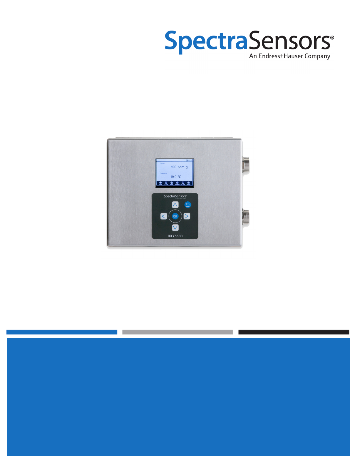
OXY5500 Oxygen Analyzer
Operator’s Manual
P/N 4900002239 rev G


OXY5500 Oxygen
Analyzer
Operator’s Manual
Products of
4333 W Sam Houston Pkwy N, Suite 100
Houston, TX 77043-1223
Tel: 800.619.2861
Fax: 713.856.6623
www.spectrasensors.com
Copyright © 2017 SpectraSensors, Inc. No part of this manual may be reproduced in
whole or in part without the express written permission of SpectraSensors, Inc.
SpectraSensors reserves the right to change product design and specifications at any
time without prior notice.

Revision History
Revision Engineering Order Date
A EO16318 Sept. 11, 2015
B ECR16427 Jan. 12, 2016
C ECR16491 Feb. 12, 2016
D ECR16527 March 4, 2016
E ECR16973 Feb. 23, 2017
F ECR17047 April 7, 2017
G ECR17157 July 11, 2017

TABLE OF CONTENTS
List of Figures . . . . . . . . . . . . . . . . . . . . . . . . . . . . . . . . . . . . . . . . . . . . . . .1
List of Tables . . . . . . . . . . . . . . . . . . . . . . . . . . . . . . . . . . . . . . . . . . . . . . . .1
1: Introduction
Who Should Read This Manual . . . . . . . . . . . . . . . . . . . . . . . . . . . . . . . . . . . . 1-1
How to Use This Manual. . . . . . . . . . . . . . . . . . . . . . . . . . . . . . . . . . . . . . . . . 1-1
General Warnings and Cautions . . . . . . . . . . . . . . . . . . . . . . . . . . . . . . . . . 1-1
Equipment Labels . . . . . . . . . . . . . . . . . . . . . . . . . . . . . . . . . . . . . . . . 1-1
Instructional Symbols . . . . . . . . . . . . . . . . . . . . . . . . . . . . . . . . . . . . . 1-2
Conventions Used in this Manual . . . . . . . . . . . . . . . . . . . . . . . . . . . . . . . . 1-3
Documents Provided with the OXY5500 Analyzer . . . . . . . . . . . . . . . . . . . . . . . 1-3
SpectraSensors Overview . . . . . . . . . . . . . . . . . . . . . . . . . . . . . . . . . . . . . . . 1-3
About the OXY5500 Analyzer . . . . . . . . . . . . . . . . . . . . . . . . . . . . . . . . . . . . . 1-4
Temperature . . . . . . . . . . . . . . . . . . . . . . . . . . . . . . . . . . . . . . . . . . . . . . 1-4
Cross-sensitivity . . . . . . . . . . . . . . . . . . . . . . . . . . . . . . . . . . . . . . . . . . . 1-4
Getting Familiar with the Analyzer . . . . . . . . . . . . . . . . . . . . . . . . . . . . . . . . . 1-4
Housing for Oxygen in Natural Gas . . . . . . . . . . . . . . . . . . . . . . . . . . . . . . 1-6
Oxygen Probe . . . . . . . . . . . . . . . . . . . . . . . . . . . . . . . . . . . . . . . . . . . . . 1-6
Schematic drawing for the Oxygen Probe. . . . . . . . . . . . . . . . . . . . . . . . 1-7
How does an oxygen sensor work?. . . . . . . . . . . . . . . . . . . . . . . . . . . . . . . 1-7
Safety Guidelines . . . . . . . . . . . . . . . . . . . . . . . . . . . . . . . . . . . . . . . . . . . . . 1-8
2: Installation
What Should be Included in the Shipping Box . . . . . . . . . . . . . . . . . . . . . . . . . 2-1
Inspecting the Analyzer . . . . . . . . . . . . . . . . . . . . . . . . . . . . . . . . . . . . . . . . . 2-1
Lifting/carrying the analyzer . . . . . . . . . . . . . . . . . . . . . . . . . . . . . . . . . . . 2-1
Installing the Analyzer. . . . . . . . . . . . . . . . . . . . . . . . . . . . . . . . . . . . . . . . . . 2-2
Required Basic Equipment . . . . . . . . . . . . . . . . . . . . . . . . . . . . . . . . . . . . . . . 2-2
Hardware and Tools for Installation. . . . . . . . . . . . . . . . . . . . . . . . . . . . . . . . . 2-2
Mounting the Analyzer. . . . . . . . . . . . . . . . . . . . . . . . . . . . . . . . . . . . . . . . . . 2-3
Connecting Electrical Power to the Analyzer . . . . . . . . . . . . . . . . . . . . . . . . . . . 2-4
AC Connection. . . . . . . . . . . . . . . . . . . . . . . . . . . . . . . . . . . . . . . . . . . . . 2-4
DC Connection. . . . . . . . . . . . . . . . . . . . . . . . . . . . . . . . . . . . . . . . . . . . . 2-4
Protective chassis and ground connections . . . . . . . . . . . . . . . . . . . . . . . . . 2-5
Analyzer Connections . . . . . . . . . . . . . . . . . . . . . . . . . . . . . . . . . . . . . . . . . . 2-7
Connecting the Analog Outputs/Analog Inputs . . . . . . . . . . . . . . . . . . . . . . . . . 2-8
3: Operation
Operation Overview . . . . . . . . . . . . . . . . . . . . . . . . . . . . . . . . . . . . . . . . . . . 3-1
Sensor Menu . . . . . . . . . . . . . . . . . . . . . . . . . . . . . . . . . . . . . . . . . . . . . . . . 3-3
Measurement Settings Menu . . . . . . . . . . . . . . . . . . . . . . . . . . . . . . . . . . . . . 3-5
To enter editing mode . . . . . . . . . . . . . . . . . . . . . . . . . . . . . . . . . . . . . . . 3-6
To exit editing mode . . . . . . . . . . . . . . . . . . . . . . . . . . . . . . . . . . . . . . . . 3-6
Measurement Menu. . . . . . . . . . . . . . . . . . . . . . . . . . . . . . . . . . . . . . . . . . . . 3-7
Device Settings Menu . . . . . . . . . . . . . . . . . . . . . . . . . . . . . . . . . . . . . . . . . . 3-8
Digitals Menu . . . . . . . . . . . . . . . . . . . . . . . . . . . . . . . . . . . . . . . . . . . . . . . . 3-8
To enter editing mode . . . . . . . . . . . . . . . . . . . . . . . . . . . . . . . . . . . . . . . 3-9
To exit the editing mode . . . . . . . . . . . . . . . . . . . . . . . . . . . . . . . . . . . . . . 3-9
Analog Output Settings (Analogues) Menu . . . . . . . . . . . . . . . . . . . . . . . . . . . 3-10
To enter editing mode . . . . . . . . . . . . . . . . . . . . . . . . . . . . . . . . . . . . . . 3-11
To exit editing mode . . . . . . . . . . . . . . . . . . . . . . . . . . . . . . . . . . . . . . . 3-11
OXY5500 Operator’s Manual i

Oxygen Analyzer
Starting Up the Analyzer . . . . . . . . . . . . . . . . . . . . . . . . . . . . . . . . . . . . . . . 3-11
Sensor Menu Options . . . . . . . . . . . . . . . . . . . . . . . . . . . . . . . . . . . . . . . . . 3-12
Change Parameters . . . . . . . . . . . . . . . . . . . . . . . . . . . . . . . . . . . . . . . . 3-12
To enter editing mode . . . . . . . . . . . . . . . . . . . . . . . . . . . . . . . . . . . . 3-13
To exit editing mode . . . . . . . . . . . . . . . . . . . . . . . . . . . . . . . . . . . . . 3-13
Changing the Sensor Type . . . . . . . . . . . . . . . . . . . . . . . . . . . . . . . . . . . 3-13
To manually change the sensor constants values . . . . . . . . . . . . . . . . . 3-14
Calibration . . . . . . . . . . . . . . . . . . . . . . . . . . . . . . . . . . . . . . . . . . . . . . 3-15
Pre-Calibration . . . . . . . . . . . . . . . . . . . . . . . . . . . . . . . . . . . . . . . . . 3-15
Manual calibration. . . . . . . . . . . . . . . . . . . . . . . . . . . . . . . . . . . . . . . 3-16
Two-point calibration. . . . . . . . . . . . . . . . . . . . . . . . . . . . . . . . . . . . . 3-17
Calibration Pressure . . . . . . . . . . . . . . . . . . . . . . . . . . . . . . . . . . . . . 3-19
Calibration Temperature . . . . . . . . . . . . . . . . . . . . . . . . . . . . . . . . . . 3-20
Calibration . . . . . . . . . . . . . . . . . . . . . . . . . . . . . . . . . . . . . . . . . . . . 3-21
Relative Accuracy Test Audit (RATA) . . . . . . . . . . . . . . . . . . . . . . . . . . . . 3-22
To enter editing mode . . . . . . . . . . . . . . . . . . . . . . . . . . . . . . . . . . . . 3-23
To exit editing mode . . . . . . . . . . . . . . . . . . . . . . . . . . . . . . . . . . . . . 3-23
Pressure for RATA calculation . . . . . . . . . . . . . . . . . . . . . . . . . . . . . . . 3-24
Temperature for RATA Calculation. . . . . . . . . . . . . . . . . . . . . . . . . . . . 3-24
Measurement Settings Options . . . . . . . . . . . . . . . . . . . . . . . . . . . . . . . . . . . 3-26
Temperature compensation. . . . . . . . . . . . . . . . . . . . . . . . . . . . . . . . . . . 3-26
Pressure compensation. . . . . . . . . . . . . . . . . . . . . . . . . . . . . . . . . . . . . . 3-27
Interval . . . . . . . . . . . . . . . . . . . . . . . . . . . . . . . . . . . . . . . . . . . . . . . . 3-29
Logging and data management . . . . . . . . . . . . . . . . . . . . . . . . . . . . . . . . 3-30
Measurement Options . . . . . . . . . . . . . . . . . . . . . . . . . . . . . . . . . . . . . . . . . 3-33
Simple screen . . . . . . . . . . . . . . . . . . . . . . . . . . . . . . . . . . . . . . . . . . . . 3-33
Details screen . . . . . . . . . . . . . . . . . . . . . . . . . . . . . . . . . . . . . . . . . . . . 3-35
Error Codes . . . . . . . . . . . . . . . . . . . . . . . . . . . . . . . . . . . . . . . . . . . 3-36
Graph screen. . . . . . . . . . . . . . . . . . . . . . . . . . . . . . . . . . . . . . . . . . . . . 3-38
Device Settings Options . . . . . . . . . . . . . . . . . . . . . . . . . . . . . . . . . . . . . . . . 3-39
Device settings screen . . . . . . . . . . . . . . . . . . . . . . . . . . . . . . . . . . . . . . 3-39
About screen . . . . . . . . . . . . . . . . . . . . . . . . . . . . . . . . . . . . . . . . . . . . . 3-41
Sensor details screen . . . . . . . . . . . . . . . . . . . . . . . . . . . . . . . . . . . . . . . 3-41
Digitals Menu Options . . . . . . . . . . . . . . . . . . . . . . . . . . . . . . . . . . . . . . . . . 3-42
RS-232 settings . . . . . . . . . . . . . . . . . . . . . . . . . . . . . . . . . . . . . . . . . . . 3-42
RS-485 settings . . . . . . . . . . . . . . . . . . . . . . . . . . . . . . . . . . . . . . . . . . . 3-43
TCP/IP settings . . . . . . . . . . . . . . . . . . . . . . . . . . . . . . . . . . . . . . . . . . . 3-44
Analog Output Settings (Analogues) Options . . . . . . . . . . . . . . . . . . . . . . . . . 3-44
4-20mA interface settings . . . . . . . . . . . . . . . . . . . . . . . . . . . . . . . . . . . . 3-45
4-20mA values . . . . . . . . . . . . . . . . . . . . . . . . . . . . . . . . . . . . . . . . . . . 3-46
Concentration alarm relay. . . . . . . . . . . . . . . . . . . . . . . . . . . . . . . . . . . . 3-48
4-20mA calibration. . . . . . . . . . . . . . . . . . . . . . . . . . . . . . . . . . . . . . . . . 3-49
Output calibration . . . . . . . . . . . . . . . . . . . . . . . . . . . . . . . . . . . . . . . 3-49
Input calibration . . . . . . . . . . . . . . . . . . . . . . . . . . . . . . . . . . . . . . . . 3-50
4: Modbus Communication
Introduction . . . . . . . . . . . . . . . . . . . . . . . . . . . . . . . . . . . . . . . . . . . . . . . . . 4-1
Protocol Definition. . . . . . . . . . . . . . . . . . . . . . . . . . . . . . . . . . . . . . . . . . . . . 4-1
General Specification . . . . . . . . . . . . . . . . . . . . . . . . . . . . . . . . . . . . . . . . 4-1
Function Codes . . . . . . . . . . . . . . . . . . . . . . . . . . . . . . . . . . . . . . . . . . . . 4-2
Data Formats . . . . . . . . . . . . . . . . . . . . . . . . . . . . . . . . . . . . . . . . . . . . . 4-2
Float . . . . . . . . . . . . . . . . . . . . . . . . . . . . . . . . . . . . . . . . . . . . . . . . . 4-2
Int32. . . . . . . . . . . . . . . . . . . . . . . . . . . . . . . . . . . . . . . . . . . . . . . . . 4-2
Character . . . . . . . . . . . . . . . . . . . . . . . . . . . . . . . . . . . . . . . . . . . . . 4-2
Boolean . . . . . . . . . . . . . . . . . . . . . . . . . . . . . . . . . . . . . . . . . . . . . . 4-3
Error response . . . . . . . . . . . . . . . . . . . . . . . . . . . . . . . . . . . . . . . . . . . . 4-3
Different Communication Channels . . . . . . . . . . . . . . . . . . . . . . . . . . . . . . 4-3
Recommendation . . . . . . . . . . . . . . . . . . . . . . . . . . . . . . . . . . . . . . . . 4-3
Holding Registers . . . . . . . . . . . . . . . . . . . . . . . . . . . . . . . . . . . . . . . . . . . . . 4-4
Measurement Control . . . . . . . . . . . . . . . . . . . . . . . . . . . . . . . . . . . . . . . 4-12
ii 4900002239 rev. G 7-11-17

Table of Contents
Compensation Temperature . . . . . . . . . . . . . . . . . . . . . . . . . . . . . . . . . . 4-13
Measurement Interval . . . . . . . . . . . . . . . . . . . . . . . . . . . . . . . . . . . . . . 4-13
Device ID RS-485, RS-232 and Ethernet. . . . . . . . . . . . . . . . . . . . . . . . . . 4-13
Measurement Values . . . . . . . . . . . . . . . . . . . . . . . . . . . . . . . . . . . . . . . 4-14
4-20mA Port1 Calibration Values . . . . . . . . . . . . . . . . . . . . . . . . . . . . . . . 4-15
4-20mA Port2 Calibration Values . . . . . . . . . . . . . . . . . . . . . . . . . . . . . . . 4-16
4-20mA Input Calibration Values . . . . . . . . . . . . . . . . . . . . . . . . . . . . . . . 4-16
Analog Input and Output Value Ranges . . . . . . . . . . . . . . . . . . . . . . . . . . 4-16
Ethernet IP . . . . . . . . . . . . . . . . . . . . . . . . . . . . . . . . . . . . . . . . . . . . . . 4-17
Ethernet Subnet Mask . . . . . . . . . . . . . . . . . . . . . . . . . . . . . . . . . . . . . . 4-18
Examples . . . . . . . . . . . . . . . . . . . . . . . . . . . . . . . . . . . . . . . . . . . . . . . . . . 4-18
Configuration of a Continuous Measurement . . . . . . . . . . . . . . . . . . . . . . . 4-18
Configuration of an Analog Output . . . . . . . . . . . . . . . . . . . . . . . . . . . . . . 4-19
1-Point Calibration of an OP-9 Sensor . . . . . . . . . . . . . . . . . . . . . . . . . . . 4-20
Appendix A: Specifications
Technical Notes . . . . . . . . . . . . . . . . . . . . . . . . . . . . . . . . . . . . . . . . . . . . . . A-2
Spare Parts . . . . . . . . . . . . . . . . . . . . . . . . . . . . . . . . . . . . . . . . . . . . . . . . . A-6
Appendix B: Troubleshooting & Maintenance
Potential Risks Affecting Personnel . . . . . . . . . . . . . . . . . . . . . . . . . . . . . . . . . B-1
Mitigating risks . . . . . . . . . . . . . . . . . . . . . . . . . . . . . . . . . . . . . . . . . . . . B-1
Electrocution hazard . . . . . . . . . . . . . . . . . . . . . . . . . . . . . . . . . . . . . . B-1
Explosion hazard . . . . . . . . . . . . . . . . . . . . . . . . . . . . . . . . . . . . . . . . B-1
Electrostatic discharge. . . . . . . . . . . . . . . . . . . . . . . . . . . . . . . . . . . . . B-2
Optical Output . . . . . . . . . . . . . . . . . . . . . . . . . . . . . . . . . . . . . . . . . . . . . . . B-2
Cleaning the Instrument . . . . . . . . . . . . . . . . . . . . . . . . . . . . . . . . . . . . . . . . B-2
SMA-fiber connector. . . . . . . . . . . . . . . . . . . . . . . . . . . . . . . . . . . . . . . . . B-2
Oxygen probe . . . . . . . . . . . . . . . . . . . . . . . . . . . . . . . . . . . . . . . . . . . . . B-2
Tools and materials. . . . . . . . . . . . . . . . . . . . . . . . . . . . . . . . . . . . . . . B-2
Temperature Probe Lifespan. . . . . . . . . . . . . . . . . . . . . . . . . . . . . . . . . . . . . . B-3
Replacing the Fuse . . . . . . . . . . . . . . . . . . . . . . . . . . . . . . . . . . . . . . . . . . . . B-3
Replacing the Electro-Optical Module. . . . . . . . . . . . . . . . . . . . . . . . . . . . . . . . B-5
Required tools and hardware. . . . . . . . . . . . . . . . . . . . . . . . . . . . . . . . . . . B-5
Installing/Replacing the Pressure Sensor . . . . . . . . . . . . . . . . . . . . . . . . . . . . . B-7
Required tools . . . . . . . . . . . . . . . . . . . . . . . . . . . . . . . . . . . . . . . . . . . . . B-8
Removing and Replacing the Oxygen Probe . . . . . . . . . . . . . . . . . . . . . . . . . . B-11
Tools/Parts . . . . . . . . . . . . . . . . . . . . . . . . . . . . . . . . . . . . . . . . . . . . . . B-11
Removing the Oxygen Probe . . . . . . . . . . . . . . . . . . . . . . . . . . . . . . . . . . B-11
Replacing the Oxygen Probe . . . . . . . . . . . . . . . . . . . . . . . . . . . . . . . . . . B-15
Correcting Error Codes . . . . . . . . . . . . . . . . . . . . . . . . . . . . . . . . . . . . . . . . B-17
High signal strength; low O2 or no O2 on OP-3, OP-6 or OP-9 probe . . . . . . B-17
Low signal strength; high O2 on OP-3, OP-6 or OP-9 probe. . . . . . . . . . . . . B-17
Recommendations for Correct Measurement . . . . . . . . . . . . . . . . . . . . . . . . . B-17
Signal Drifts due to Oxygen Gradients . . . . . . . . . . . . . . . . . . . . . . . . . . . B-17
Signal Drifts due to Temperature Gradients. . . . . . . . . . . . . . . . . . . . . . . . B-18
Signal Drift due to Photo-decomposition . . . . . . . . . . . . . . . . . . . . . . . . . . B-18
Performance Improvement. . . . . . . . . . . . . . . . . . . . . . . . . . . . . . . . . . . . . . B-18
Troubleshooting . . . . . . . . . . . . . . . . . . . . . . . . . . . . . . . . . . . . . . . . . . . . . B-19
Service Contact . . . . . . . . . . . . . . . . . . . . . . . . . . . . . . . . . . . . . . . . . . . . . B-20
Customer Service. . . . . . . . . . . . . . . . . . . . . . . . . . . . . . . . . . . . . . . . . B-20
Service Repair Order . . . . . . . . . . . . . . . . . . . . . . . . . . . . . . . . . . . . . . . B-20
Before contacting Technical Service . . . . . . . . . . . . . . . . . . . . . . . . . . . . . B-20
Packing and Storage . . . . . . . . . . . . . . . . . . . . . . . . . . . . . . . . . . . . . . . . . . B-21
Storage . . . . . . . . . . . . . . . . . . . . . . . . . . . . . . . . . . . . . . . . . . . . . . . . . . . B-22
Disclaimers . . . . . . . . . . . . . . . . . . . . . . . . . . . . . . . . . . . . . . . . . . . . . . . . B-22
Warranty . . . . . . . . . . . . . . . . . . . . . . . . . . . . . . . . . . . . . . . . . . . . . . . . . . B-22
Index . . . . . . . . . . . . . . . . . . . . . . . . . . . . . . . . . . . . . . . . . . . . . . . . . Index-1
OXY5500 Operator’s Manual iii

Oxygen Analyzer
THIS PAGE INTENTIONALLY LEFT BLANK
iv 4900002239 rev. G 7-11-17

LIST OF FIGURES
Figure 1–1. OXY5500 analyzer . . . . . . . . . . . . . . . . . . . . . . . . . . . . . . . . . . 1-5
Figure 1–2. Inside cabinet view . . . . . . . . . . . . . . . . . . . . . . . . . . . . . . . . . . 1-5
Figure 1–3. Standard fiber-optic oxygen sensors fittings. . . . . . . . . . . . . . . . . 1-6
Figure 1–4. OXY5500 probe tips . . . . . . . . . . . . . . . . . . . . . . . . . . . . . . . . . 1-7
Figure 1–5. Trace oxygen probe schematic . . . . . . . . . . . . . . . . . . . . . . . . . . 1-7
Figure 1–6. Principle of dynamic quenching of luminescence by
molecular oxygen . . . . . . . . . . . . . . . . . . . . . . . . . . . . . . . . . . . 1-8
Figure 2–1. Analyzer mounting locations . . . . . . . . . . . . . . . . . . . . . . . . . . . 2-4
Figure 2–2. AC/DC power connections . . . . . . . . . . . . . . . . . . . . . . . . . . . . . 2-7
Figure 2–3. Analyzer connections. . . . . . . . . . . . . . . . . . . . . . . . . . . . . . . . . 2-8
Figure 3–1. Main menu screen. . . . . . . . . . . . . . . . . . . . . . . . . . . . . . . . . . . 3-1
Figure 3–2. Warning: Timestamp reset. . . . . . . . . . . . . . . . . . . . . . . . . . . . . 3-2
Figure 3–3. OXY5500 Software Menu Map . . . . . . . . . . . . . . . . . . . . . . . . . . 3-3
Figure 3–4. Main Menu - Sensor selected . . . . . . . . . . . . . . . . . . . . . . . . . . . 3-3
Figure 3–5. Sensor Options. . . . . . . . . . . . . . . . . . . . . . . . . . . . . . . . . . . . . 3-4
Figure 3–6. Main menu screen - Measurement Settings selected . . . . . . . . . . . 3-5
Figure 3–7. Message window - Stop measurements during configuration . . . . . 3-5
Figure 3–8. Measurement Settings screen. . . . . . . . . . . . . . . . . . . . . . . . . . . 3-6
Figure 3–9. Main menu screen - Measurement selected . . . . . . . . . . . . . . . . . 3-7
Figure 3–10. Main menu screen - Device Settings selected . . . . . . . . . . . . . . . . 3-8
Figure 3–11. Main menu screen - Digitals selected . . . . . . . . . . . . . . . . . . . . . 3-8
Figure 3–12. Message window - Stop measurements during configuration . . . . . 3-9
Figure 3–13. Main menu screen - Analogues selected . . . . . . . . . . . . . . . . . . 3-10
Figure 3–14. Message window - Stop measurements during configuration . . . . 3-10
Figure 3–15. Initial screen - Self-check . . . . . . . . . . . . . . . . . . . . . . . . . . . . 3-11
Figure 3–16. Message window - Stop measurements during configurations . . . 3-12
Figure 3–17. Sensor Type and Sensor Constants - Sensor Type menu
selected for editing . . . . . . . . . . . . . . . . . . . . . . . . . . . . . . . . . 3-13
Figure 3–18. Example calibration certificate: Calibration data and
sensor constants. . . . . . . . . . . . . . . . . . . . . . . . . . . . . . . . . . . 3-14
Figure 3–19. Calibration Data screen . . . . . . . . . . . . . . . . . . . . . . . . . . . . . . 3-15
Figure 3–20. Calibration Data screen - changing the pressure unit . . . . . . . . . 3-16
Figure 3–21. Message window - Sensor type change resets RATA . . . . . . . . . . 3-17
Figure 3–22. Calibration button in the Sensor Options window . . . . . . . . . . . . 3-18
Figure 3–23. Message window - Stop measurements during configuration . . . . 3-18
Figure 3–24. Calibration settings screen . . . . . . . . . . . . . . . . . . . . . . . . . . . . 3-19
Figure 3–25. Calibration temperature screen . . . . . . . . . . . . . . . . . . . . . . . . 3-20
Figure 3–26. Calibration screen . . . . . . . . . . . . . . . . . . . . . . . . . . . . . . . . . . 3-21
Figure 3–27. Sensor Options screen. . . . . . . . . . . . . . . . . . . . . . . . . . . . . . . 3-22
Figure 3–28. Message window - Stop measurements for calibration. . . . . . . . . 3-23
Figure 3–29. Pressure for RATA Calculation . . . . . . . . . . . . . . . . . . . . . . . . . 3-24
Figure 3–30. Relative Accuracy Test Audit (RATA) Screen. . . . . . . . . . . . . . . . 3-25
Figure 3–31. Measurement Settings screen - Temperature compensation. . . . . 3-26
OXY5500 Operator’s Manual v

Oxygen Analyzer
Figure 3–32. Measurement Settings screen - Pressure compensation. . . . . . . . 3-27
Figure 3–33. Measurement Settings screen - Select time interval . . . . . . . . . . 3-29
Figure 3–34. Measurement Settings screen - Logging . . . . . . . . . . . . . . . . . . 3-30
Figure 3–35. Measurement Browser - List of measurement files . . . . . . . . . . . 3-31
Figure 3–36. Keyboard screen to enter measurement name . . . . . . . . . . . . . . 3-32
Figure 3–37. Simple measurement screen . . . . . . . . . . . . . . . . . . . . . . . . . . 3-33
Figure 3–38. Temperature sensor error message. . . . . . . . . . . . . . . . . . . . . . 3-34
Figure 3–39. Error message - sensor cannot be detected . . . . . . . . . . . . . . . . 3-34
Figure 3–40. Details measurement screen . . . . . . . . . . . . . . . . . . . . . . . . . . 3-35
Figure 3–41. Graph screen . . . . . . . . . . . . . . . . . . . . . . . . . . . . . . . . . . . . . 3-38
Figure 3–42. Y-Axis setup: Autoscale, . . . . . . . . . . . . . . . . . . . . . . . . . . . . . 3-39
Figure 3–43. Device settings screen. . . . . . . . . . . . . . . . . . . . . . . . . . . . . . . 3-40
Figure 3–44. About screen . . . . . . . . . . . . . . . . . . . . . . . . . . . . . . . . . . . . . 3-41
Figure 3–45. Sensor details screen . . . . . . . . . . . . . . . . . . . . . . . . . . . . . . . 3-42
Figure 3–46. Digitals - RS-232 settings . . . . . . . . . . . . . . . . . . . . . . . . . . . . 3-42
Figure 3–47. Digitals - RS-485 settings . . . . . . . . . . . . . . . . . . . . . . . . . . . . 3-43
Figure 3–48. Digitals -TCP/IP settings . . . . . . . . . . . . . . . . . . . . . . . . . . . . . 3-44
Figure 3–49. Analogues - 4-20mA interface settings . . . . . . . . . . . . . . . . . . . 3-45
Figure 3–50. Bilinear current output vs oxygen value. . . . . . . . . . . . . . . . . . . 3-46
Figure 3–51. Analogues - 4-20mA values for Mode ‘Off’ . . . . . . . . . . . . . . . . . 3-47
Figure 3–52. 4-20mA values for Mode ‘Linear’. . . . . . . . . . . . . . . . . . . . . . . . 3-47
Figure 3–53. 4-20mA values for Mode ‘Bilinear’. . . . . . . . . . . . . . . . . . . . . . . 3-48
Figure 3–54. Analogues - Concentration alarm relay . . . . . . . . . . . . . . . . . . . 3-49
Figure 3–55. Analogues - 4-20mA calibration . . . . . . . . . . . . . . . . . . . . . . . . 3-50
Figure 3–56. Analogues - 4-20mA input calibration . . . . . . . . . . . . . . . . . . . . 3-51
Figure A–1. Outline and mounting dimensions - panel mount . . . . . . . . . . . . . A-3
Figure A–2. Interconnect diagram (AC). . . . . . . . . . . . . . . . . . . . . . . . . . . . . A-4
Figure A–3. Interconnect diagram (DC) . . . . . . . . . . . . . . . . . . . . . . . . . . . . A-5
Figure B–1. Removing the fuse cover . . . . . . . . . . . . . . . . . . . . . . . . . . . . . . B-4
Figure B–2. Removing the fuse . . . . . . . . . . . . . . . . . . . . . . . . . . . . . . . . . . B-4
Figure B–3. Inserting screwdriver into clip extension . . . . . . . . . . . . . . . . . . . B-6
Figure B–4. Disconnecting the electro-optical module from the DIN rail . . . . . . B-6
Figure B–5. Removing the ground cable . . . . . . . . . . . . . . . . . . . . . . . . . . . . B-7
Figure B–6. Removing the Swagelok nuts . . . . . . . . . . . . . . . . . . . . . . . . . . . B-8
Figure B–7. Removing the tubing. . . . . . . . . . . . . . . . . . . . . . . . . . . . . . . . . B-9
Figure B–8. Removing the wiring . . . . . . . . . . . . . . . . . . . . . . . . . . . . . . . . . B-9
Figure B–9. Removing the pressure sensor . . . . . . . . . . . . . . . . . . . . . . . . . B-10
Figure B–10. Remove cable gland cap . . . . . . . . . . . . . . . . . . . . . . . . . . . . . B-12
Figure B–11. Remove tube nut . . . . . . . . . . . . . . . . . . . . . . . . . . . . . . . . . . B-12
Figure B–12. Remove conduit bracket . . . . . . . . . . . . . . . . . . . . . . . . . . . . . B-13
Figure B–13. Remove conduit clamp . . . . . . . . . . . . . . . . . . . . . . . . . . . . . . B-13
Figure B–14. Remove probe from Tee union (panel side) . . . . . . . . . . . . . . . . B-14
Figure B–15. Fittings on oxygen probe (panel side) . . . . . . . . . . . . . . . . . . . . B-14
Figure B–16. Remove connector nut (analyzer side). . . . . . . . . . . . . . . . . . . . B-15
Figure B–17. Preparing the new oxygen probe . . . . . . . . . . . . . . . . . . . . . . . B-15
Figure B–18. Remove probe safety cap (analyzer side). . . . . . . . . . . . . . . . . . B-16
vi 4900002239 rev. G 7-11-17

LIST OF TABLES
Table 2–1. Terminal Block TB1 . . . . . . . . . . . . . . . . . . . . . . . . . . . . . . . . . . 2-9
Table 2–2. Terminal Block TB2 . . . . . . . . . . . . . . . . . . . . . . . . . . . . . . . . . 2-10
Table 3–1. Calibration Specifications . . . . . . . . . . . . . . . . . . . . . . . . . . . . . 3-16
Table 3–2. Error Codes . . . . . . . . . . . . . . . . . . . . . . . . . . . . . . . . . . . . . . 3-37
Table 4–1. Holding registers . . . . . . . . . . . . . . . . . . . . . . . . . . . . . . . . . . . 4-4
Table 4–2. Definition of register 5707 . . . . . . . . . . . . . . . . . . . . . . . . . . . . 4-12
Table 4–3. Measurement control register bit definition . . . . . . . . . . . . . . . . 4-12
Table 4–4. Definition of register 2411 . . . . . . . . . . . . . . . . . . . . . . . . . . . . 4-13
Table 4–5. Definition of register 3499 . . . . . . . . . . . . . . . . . . . . . . . . . . . . 4-13
Table 4–6. Definition of register 4095 . . . . . . . . . . . . . . . . . . . . . . . . . . . . 4-13
Table 4–7. Definition of register 4109 . . . . . . . . . . . . . . . . . . . . . . . . . . . . 4-14
Table 4–8. Definition of register 5695 . . . . . . . . . . . . . . . . . . . . . . . . . . . . 4-14
Table 4–9. Definition of register 4895 . . . . . . . . . . . . . . . . . . . . . . . . . . . . 4-14
Table 4–10. Error Codes for the error register . . . . . . . . . . . . . . . . . . . . . . . 4-15
Table 4–11. Definition of register 4329 . . . . . . . . . . . . . . . . . . . . . . . . . . . . 4-15
Table 4–12. Definition of register 4979 . . . . . . . . . . . . . . . . . . . . . . . . . . . . 4-16
Table 4–13. Definition of register 5667 . . . . . . . . . . . . . . . . . . . . . . . . . . . . 4-16
Table 4–14. Oxygen units for various output, sensor and
measurement mode configuration. . . . . . . . . . . . . . . . . . . . . . . 4-16
Table 4–15. Definition of register 5677 . . . . . . . . . . . . . . . . . . . . . . . . . . . . 4-17
Table 4–16. Definition of register 5685 . . . . . . . . . . . . . . . . . . . . . . . . . . . . 4-18
Table 4–17. Configuration for a continuous measurement . . . . . . . . . . . . . . . 4-18
Table 4–18. Reading measurement example . . . . . . . . . . . . . . . . . . . . . . . . 4-19
Table 4–19. Configuration for an analog output . . . . . . . . . . . . . . . . . . . . . . 4-20
Table 4–20. 1-Point calibration of a OP-9 sensor . . . . . . . . . . . . . . . . . . . . . 4-20
Table 4–21. Measurement reading for calibration process example. . . . . . . . . 4-21
Table A–1. OXY5500 analyzer specifications. . . . . . . . . . . . . . . . . . . . . . . . . A-1
Table A–2. Replacement parts for OXY5500 analyzer . . . . . . . . . . . . . . . . . . A-6
Table B–1. Fuse specifications . . . . . . . . . . . . . . . . . . . . . . . . . . . . . . . . . . B-5
Table B–2. Sensor drift at zero reading (0 ppb) recording 3600, 50000
and 100000 data points. . . . . . . . . . . . . . . . . . . . . . . . . . . . . . B-18
Table B–3. Potential instrument problems and their solutions. . . . . . . . . . . . B-19
OXY5500 Operator’s Manual vii

Oxygen Analyzer
THIS PAGE INTENTIONALLY LEFT BLANK
viii 4900002239 rev. G 7-11-17
1 - INTRODUCTION
SpectraSensors’ OXY5500 analyzer is a stand-alone oxygen meter designed to
detect oxygen in gases such as Natural Gas and air. Its design is based on
fluorescence quenching technology that creates very stable, internally
referenced measured values.
Who Should Read This Manual
This manual should be read and referenced by anyone installing, operating or
having direct contact with the analyzer.
How to Use This Manual
Take a moment to familiarize yourself with this Operator’s Manual by reading
the "Table of Contents".
There are a number of options and accessories available for the OXY5500
analyzers. This manual has been written to address the most common options
and accessories. Images, tables and charts have been included to provide a
visual understanding of the analyzer and its functions. Special symbols are also
used to provide the user with key information regarding the system
configuration and/or operation. Pay close attention to this information.
General Warnings and Cautions
Instructional icons are provided in this manual to alert the user of potential
hazards, important information and valuable tips. Following are the symbols
and associated warning and caution types to observe when servicing the
analyzer.
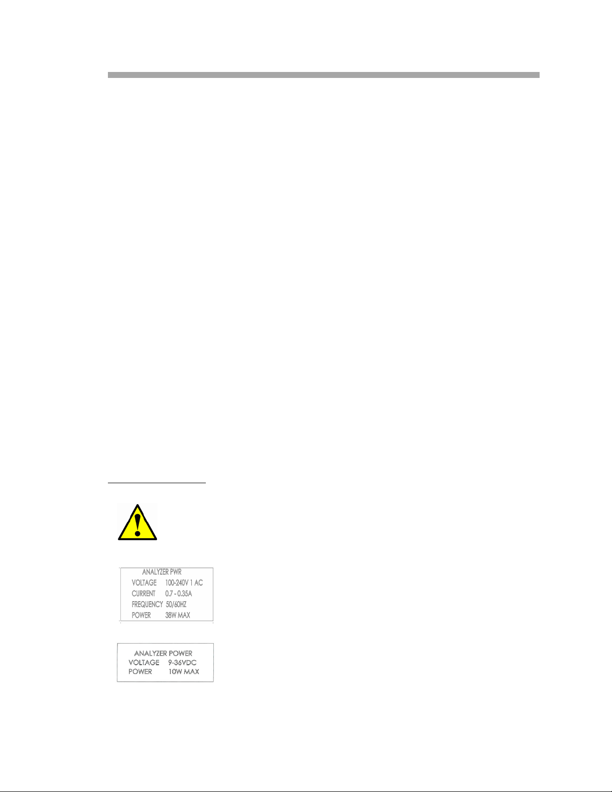
Equipment Labels
Failure to follow all directions may result in damage or
malfunction of the analyzer.
Power specifications for AC connection.
Power specifications for DC connection.
OXY5500 Operator’s Manual 1–1
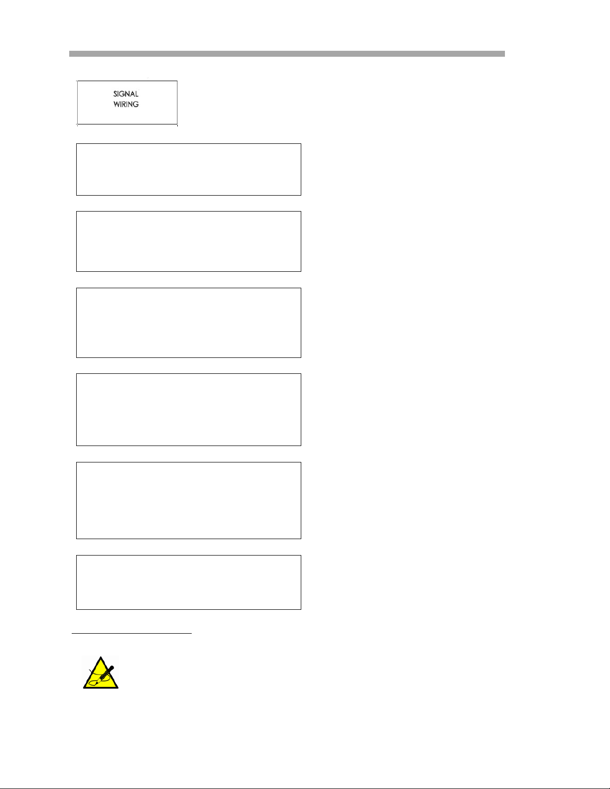
Oxygen Analyzer
Access for signal wiring.
WARNING - POTENTIAL ELECTROSTATIC CHARGING HAZARD –
SEE INSTRUCTIONS
______________________________________________________
AVERTISSEMENT - DANGER DE CHARGE ELECTROSTATIQUE
POTENTIELS - VOIR LES INSTRUCTIONS
WARNING - USE DAMP CLOTH TO CLEAN DISPLAY AND KEYPAD
TO AVOID STATIC ELECTRICITY DISCHARGE.
______________________________________________________
AVERTISSEMENT - AUX CHARGES ELECTROSTATIQUES.
UTILISER UN CHIFFON HUMIDE POUR NETTOYER L’AFFICHEUR
ET LE CLAVIER.
WARNING - EXPLOSION HAZARD – SUBSTITUTION OF COMPONENTS MAY IMPAIR SUITABILITY FOR CLASS I, DIVISION 2 OR
ZONE 2 (II 3G)
______________________________________________________
AVERTISSEMENT - RISQUE D'EXPLOSION – LA SUBSTITUTIOND
E COMPOSANTSP EUTR ENDRE CE MATERIEL INACCEPTABLE
POUR LES EMPLACEMENTS DE CLASSE I, DIVISION 2
Follow instructions to avoid
electrostatic discharge.
Use appropriate tools to
avoid electrostatic
discharge.
Substitution of components
may void certification.
WARNING - EXPLOSION HAZARD - DO NOT REPLACE ________
UNLESS POWER HAS BEEN SWITCHED OFF OR THE AREA IS
KNOWN TO BE NON-HAZARDOUS
______________________________________________________
AVERTISSEMENT - RISQUE D'EXPLOSION - COUPER LE
COURANT OU S'ASSURER QUE L'EMPLACEMENT EST DESIGNE
NON DANGEREUX AVANT DE REMPLACER LE ______
WARNING - EXPLOSION HAZARD - DO NOT DISCONNECT EQUIPMENT UNLESS POWER HAS BEEN SWITCHED OFF OR THE
AREA IS KNOWN TO BE NON-HAZARDOUS
______________________________________________________
AVERTISSEMENT - RISQUE D'EXPLOSION - AVANT DE
DECONNECTER L'EQUIPEMENT, COUPER LE COURANT OU
S'ASSURER QUE L'EMPLACEMENT EST DESIGNE NON
DANGEREUX
CAUTION: DO NOT OPERATE MACHINE WITH GROUNDING WIRE
DISCONNECTED
_______________________________________________________
ATTENTION: NE PAS METTRE L'APPAREIL EN MARCHE QUAND
LE CON DUCTEUR DE MISE A LA TERRE EST DEBRANCHE.
Instructional Symbols
General notes and important information concerning the
installation and operation of the analyzer.
Switch off power before
replacing components to
avoid explosion risk.
Switch off power before
disconnecting system to
avoid explosion risk.
Ensure grounding wire is
connected at all times
during operation.
1–2 4900002239 rev. G 7-11-17
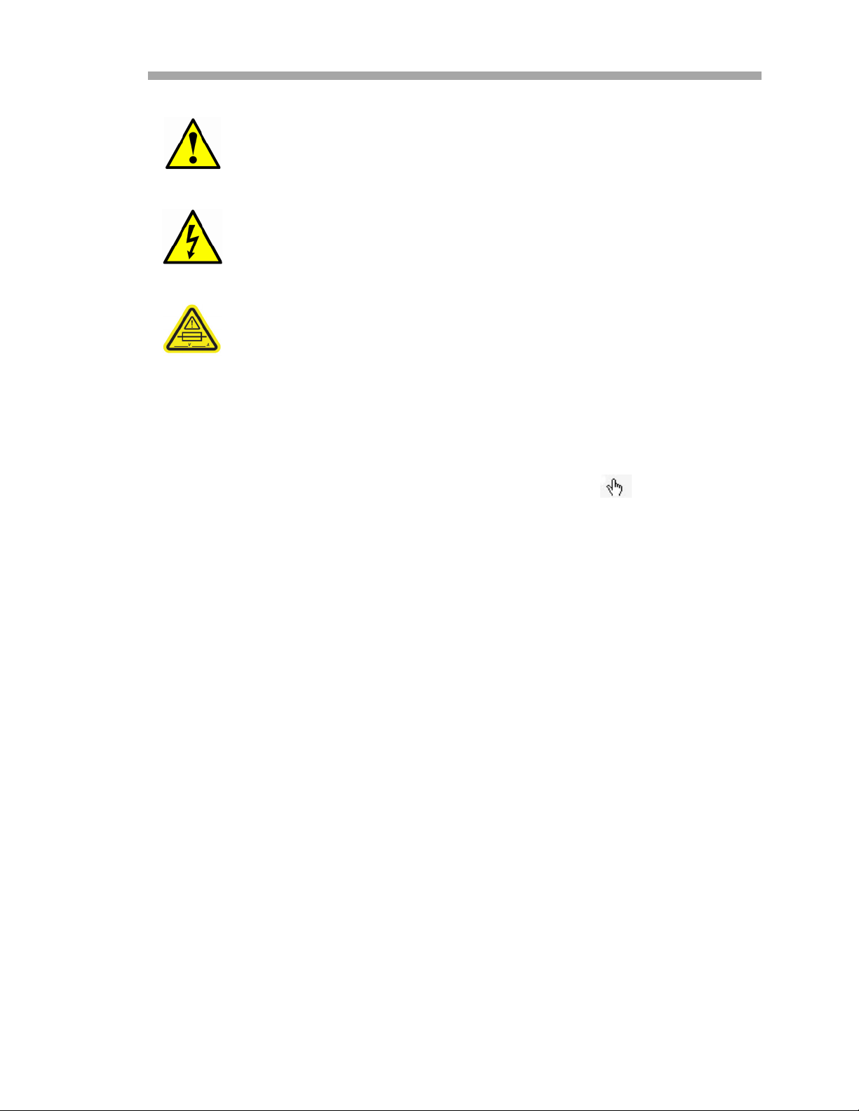
Introduction
Failure to follow all directions may result in damage or
malfunction of the analyzer.
Warning statement for hazardous voltage. Contact may cause
electric shock or burn. Turn off and lock out system before
servicing.
Maximum voltage and current specifications for fuses.
Conventions Used in this Manual
In addition to the symbols and instructional information, this manual is created
with “hot links” to enable the user to quickly navigate between different
sections within the manual. These links include table, figure and section
references and are identified by a pointing finger cursor when rolling
over the text. Simply click on the link to navigate to the associated reference.
Documents Provided with the OXY5500 Analyzer
Each OXY5500 analyzer shipped from the factory is packaged with documents
and software that may be used for system operation. Generally, the documents
included with each shipment are:
• Operator’s Manual
• Sample Conditioning System (SCS) Manual, if applicable
• Calibration Certificate
• OXY5500 Service Software Manual (and software)
• Installation Safety Manual
SpectraSensors Overview
SpectraSensors, Inc. is a leading manufacturer of technologically advanced
electro-optic gas analyzers for the industrial process, gas distribution and
environmental monitoring markets. Headquartered in Houston, Texas,
SpectraSensors was incorporated in 1999 as a spin-off of the NASA/Caltech Jet
Propulsion Laboratory (JPL) for the purpose of commercializing space-proven
measurement technologies initially developed at JPL. SpectraSensors was
acquired by the Endress + Hauser Group in 2012, which has expanded our
reach in the global marketplace.
OXY5500 Operator’s Manual 1
–3

Oxygen Analyzer
About the OXY5500 Analyzer
The OXY5500 is a stand-alone precision system enclosed in a NEMA 4X and IP66
rated stainless steel case. The rugged design and low power consumption
makes the OXY5500 ready for an indoor or outdoor application in Class 1,
Division 2, Groups A, B, C and D environments according to CSA standards
CAN/CSA C22.2 No. 0-M91, CAN/CSA C22.2 No. 94.2-07 / UL50E, CAN/CSA
C22.2 No. 213-M1987, CAN/CSA 61010-1-12, ANSI/UL 61010-1, CAN/CSA
C22.2 No. 60529:05, ANSI/ISA 12.12.01 - 2007 and ANSI/IEC 60529 - 2004.
In addition, the Oxygen analyzer is also marked as
IP66 and certified according to ATEX standard EN 60079-0:2012 + A11:2013,
EN 60079-15:2010 and IECEx standard IEC60079-0:2011 Edition 6.0 and
IEC60079-15:2010 Edition 4.
The OXY5500 is designed for three types of sensor ranges; 0-300 ppmv, 0-5%
O
and 0-50% O2. This system was specifically designed for gas measurements
2
using a flow through fiber-optic oxygen sensor mounted in a 1/4” compression
tee. The instrument LCD and data-logger are integrated into the system. The
analog outputs are programmable to provide data for oxygen and temperature.
The digital interface and PC software (included) are used for internal data
storage and external data logging. Complete control, including all calibration
and adjustments, can be completed through the PC.
II 3 G, Ex nA IIC T3 Gc
Temperature
SpectraSensors’ optical oxygen sensors must be used with an RTD Probe (Pt100
temperature sensor) in the temperature ranges shown in Table A–1 on
page A–1.
and to record temperature variations.
Each instrument is supplied with the RTD probe for compensation
Cross-sensitivity
The sensors can be used in methanol- and ethanol-water mixtures, as well as
in pure methanol and ethanol.
SpectraSensors recommends avoiding other organic solvents, such as acetone,
chloroform or methylene chloride, which may swell the sensor matrix rendering
it unusable.
There is no cross-sensitivity issues with CO
pertaining to any of three probe types.
, H2S or SO2 (iconic species)
2
Getting Familiar with the Analyzer
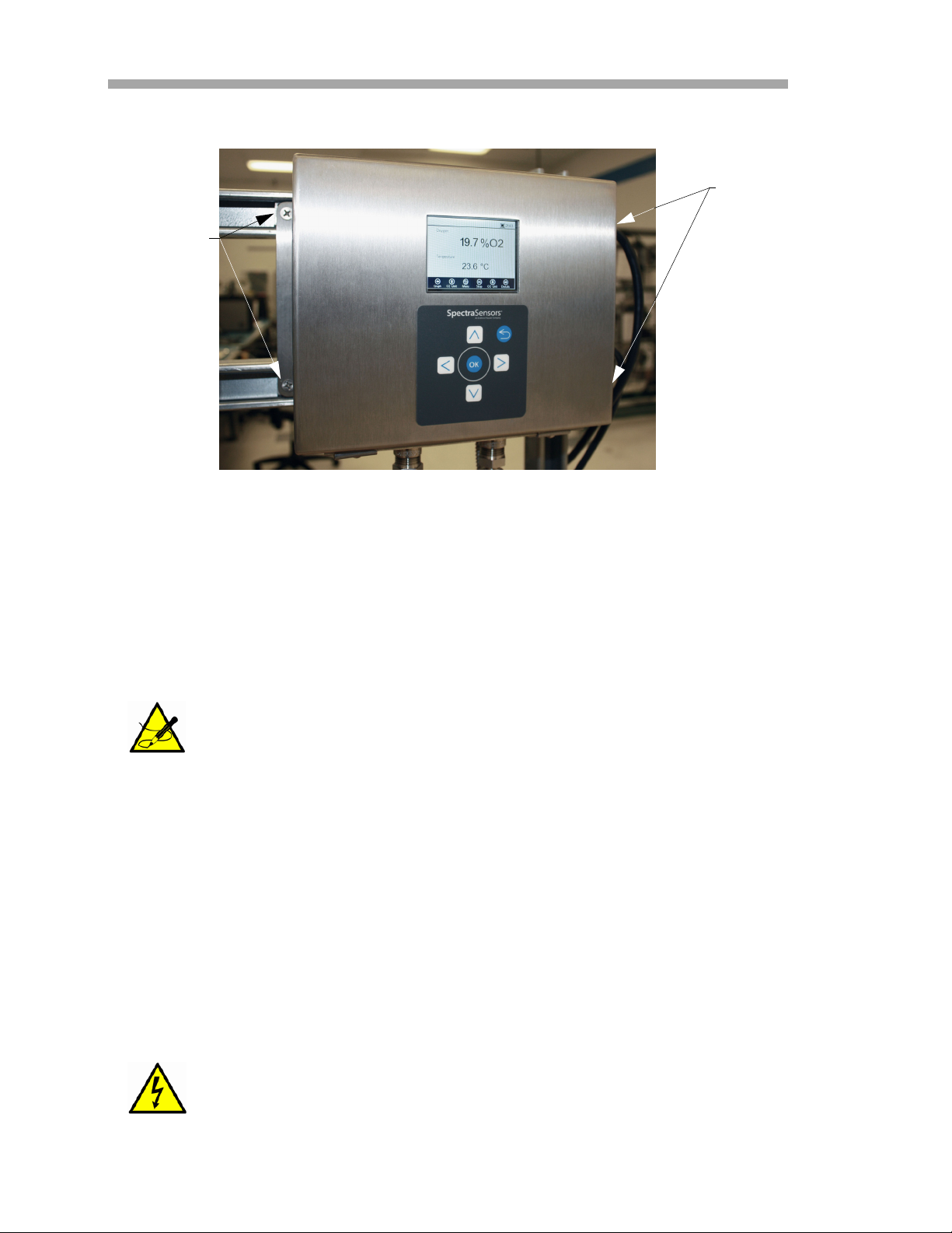
Figure 1–1 shows a sample OXY5500 analyzer. Signal wiring and analyzer
power are connected from the right side of the analyzer (facing the unit). On
the front panel of the analyzer, the LCD serves as the user interface to the
analyzer. The analyzer control electronics drive the sensor, collect the signal and
provide measurement output signals.
1–4 4900002239 rev. G 7-11-17
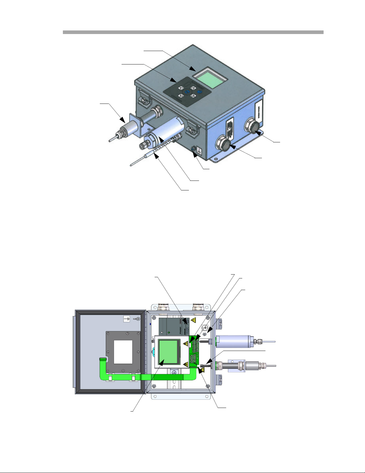
OXYGEN PROBE
Introduction
GRAPHIC DISPLAY
KEYPAD
SIGNAL WIRING
PORT
ANALYZER POWER
PORT
CHASSIS GROUND
STUD
PRESSURE SENSOR (OPTIONAL)
RTD PROBE (pt100)
Figure 1–1 OXY5500 analyzer
Inside the cabinet is the electro-optical module that provides power and other
connections to the analyzer. Refer to Figure 1–2 for an internal view of the
analyzer.
AC/DC POWER
CONNECTION
RJ-45 AND USB
CONNECTORS
RELAYS
PROTECTIVE
EARTH GROUND
OPTICAL MODULE WITH
SMA CONNECTOR
ELECTRO-OPTICAL
MODULE
FUSE ENCLOSURE
Figure 1–2 Inside cabinet view
OXY5500 Operator’s Manual 1
–5
Oxygen Analyzer
The optional sample conditioning system (SCS) contains flow devices for the
bypass loop and to control the flow to the oxygen sensor. A pressure reducing
device is also installed to reduce the pressure of the sample going to the
oxygen sensor. Depending on the application and/or ambient conditions, the
SCS may also contain a heater and thermostat to maintain the interior of the
enclosure at a constant temperature. Refer to the Sample Conditioning System
(SCS) Overview Manual for more information.
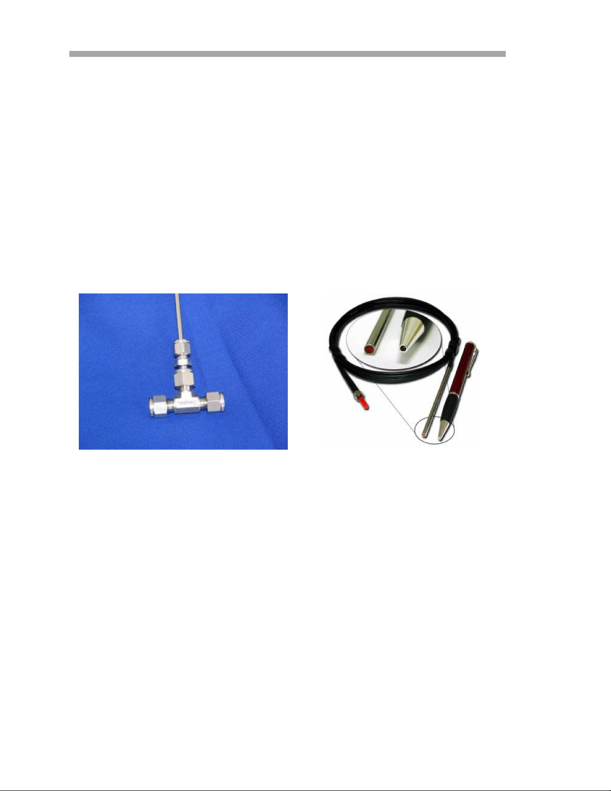
Housing for Oxygen in Natural Gas
SpectraSensors’ fiber-optic oxygen sensors are made with 2 mm polymer
optical fibers. The sensing portion is a 4 mm stainless steel probe. As a
standard, the probe is mounted in a 1/4” Swagelok Union Tee using a 1/4” x
4mm adapter as shown in Figure 1–3. Custom designs are also available.
Please contact your sales representative for more information.
1/4” compression “tee” flowthrough fitting
Figure 1–3 Standard fiber-optic oxygen sensors
fittings
4 mm oxygen dipping probe mounts in the
compression “tee”
Oxygen Probe
The oxygen sensor consists of a polymer optical fiber (POF) with a polished
distal tip that is coated with a planar oxygen-sensitive foil. The end of the
polymer optical fiber is covered with a high-grade steel tube to protect both the
sensor material and the POF. Refer to Figure 1–4. Typically, the fiber is coated
with an optical isolated sensor material in order to exclude ambient light from
the fiber tip.
1–6 4900002239 rev. G 7-11-17
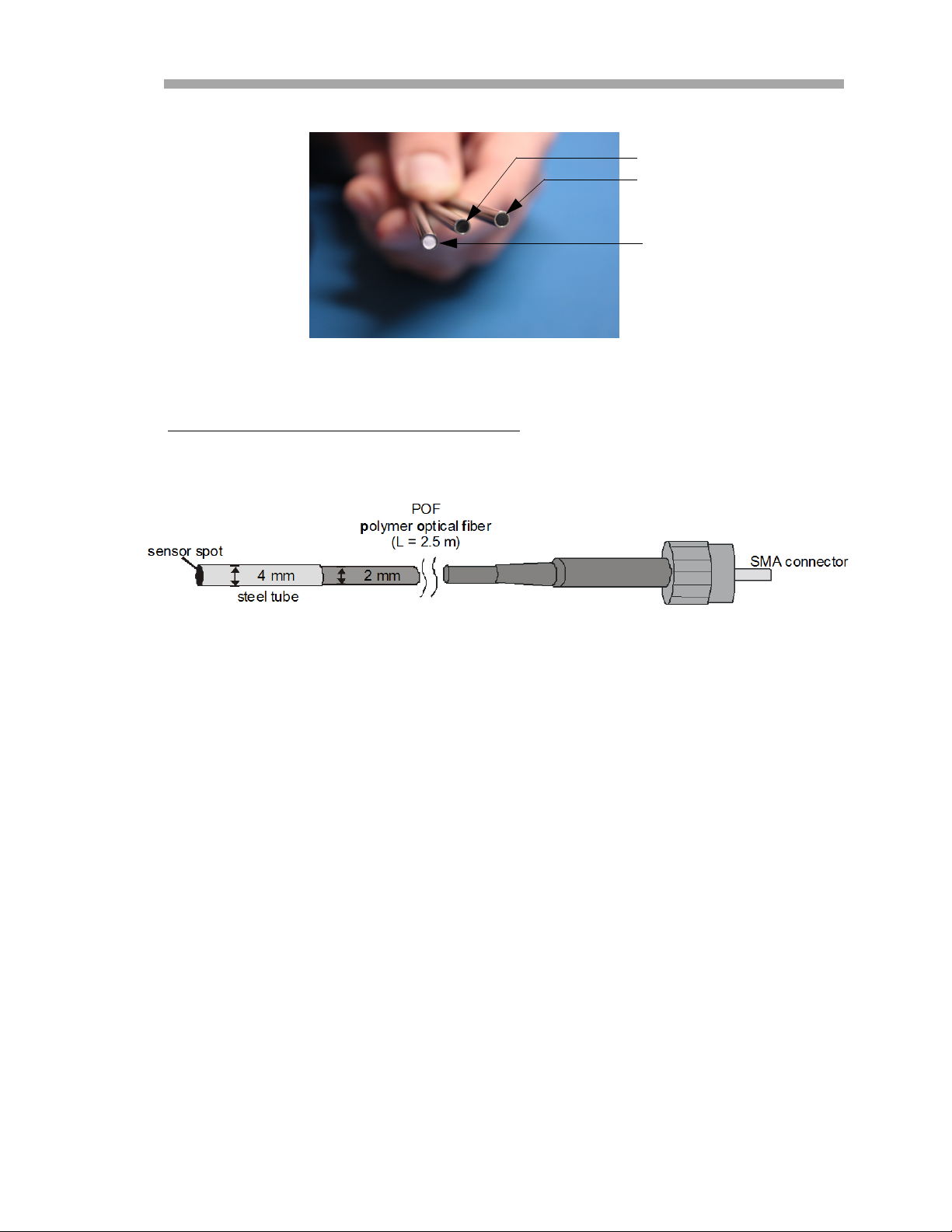
OP-3
OP-6
OP-9
Figure 1–4 OXY5500 probe tips
Schematic drawing for the Oxygen Probe
Refer to Figure 1–5 for a schematic of the trace oxygen probe.
Introduction
Figure 1–5 Trace oxygen probe schematic
This probe has a very rugged sensor with excellent long-term stability (more
than 100000 data points without drift) and is usable for process applications.
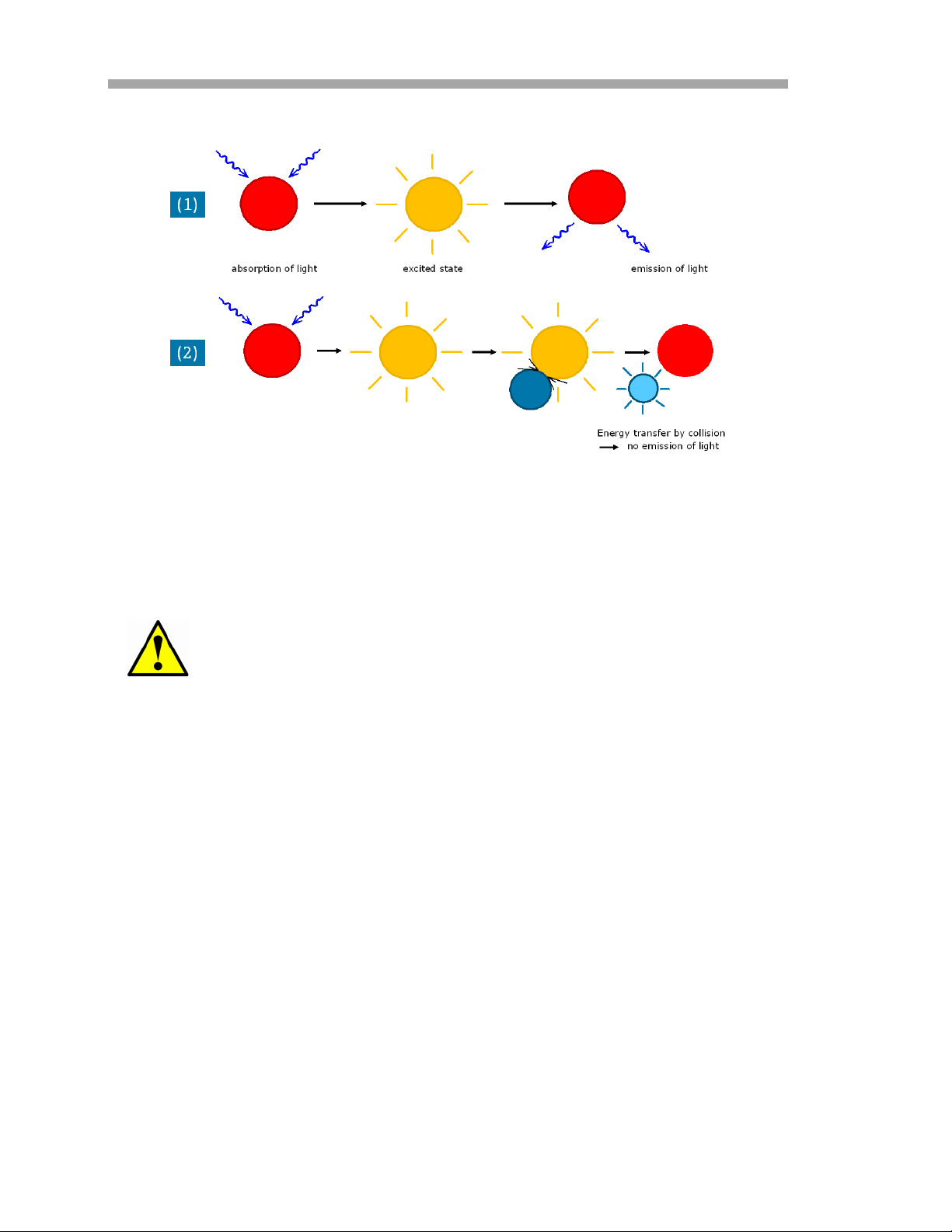
How does an oxygen sensor work?
The principle of measurement is based on the effect of dynamic luminescence
quenching by molecular oxygen. The following scheme explains the principle of
dynamic luminescence quenching by oxygen.
Principle of dynamic quenching of luminescence by molecular oxygen (refer to
Figure 1–6):
• Luminescence process in absence of oxygen (1)
• Deactivation of the luminescent indicator molecule by molecular
oxygen (2)
The collision between the oxygen-sensitive material in its excited state and the
quencher (oxygen) results in radiation-less deactivation and is called collisional
or dynamic quenching. After collision, energy transfer takes place from the
excited indicator molecule to oxygen which consequently is transferred from its
ground state (triplet state) to its excited singlet state. As a result, the indicator
molecule does not emit luminescence and the measurable luminescence signal
decreases.
OXY5500 Operator’s Manual 1
–7
Oxygen Analyzer
Figure 1–6 Principle of dynamic quenching of
luminescence by molecular oxygen
Safety Guidelines
Please read these instructions carefully before working with this
instrument. Refer also to the OXY5500 Safety Manual (P/N
4900002247) before engaging with the analyzer.
This device has been carefully tested of all functions, complying with safety
requirements, prior to leaving the factory. The correct functional and
operational safety of this instrument can only be ensured if the user observes
the necessary safety precautions and specific guidelines presented in this
manual. Refer to Appendix A, Specifications, and the list outlined below.
• Before connecting the device to the electrical supply network, ensure
that the operating voltage stated on the power supply corresponds to
the main voltage input as described in Table A–1.
• If the instrument is moved from cold to warm surroundings,
condensation may form and interfere with the functioning of the
system. In this event, wait until the instrument temperature reaches
room temperature before putting the analyzer back into operation.
• Calibration, maintenance and repair work must only be completed by
a qualified technician, trained by SpectraSensors, Inc.
• In the case of any damage to current-carrying parts, such as power
supply cable or the power supply itself, take the device out of
operation and protect it against being returned to operation.
1–8 4900002239 rev. G 7-11-17

Introduction
• If there is any reason to assume that the instrument can no longer
be operated without a risk, it must be set aside and appropriately
marked to prevent further use.
• The safety of the user may be endangered if:
– The instrument is visibly damaged
– The instrument no longer operates as specified
– The instrument has been stored under adverse conditions for a
lengthy period of time
– The instrument has been damaged in transport.
• If there is any doubt as to the working condition of the analyzer,
return the instrument to SpectraSensors for repair and maintenance.
• The operator of this measuring instrument must ensure that the
following laws and guidelines are observed when using dangerous
substances:
– National protective labor legislation
– Safety regulations for accident prevention, including National
Electrical safety standards
– Safety data sheets from the chemical manufacturer
The OXY5500 transmitter assembly is not for use in atmospheres
containing an oxygen concentration greater than 50% by volume.
OXY5500 Operator’s Manual 1
–9

Oxygen Analyzer
THIS PAGE IS INTENTIONALLY LEFT BLANK
1–10 4900002239 rev. G 7-11-17
2 - INSTALLATION
This section describes the processes used to install and setup your OXY5500
analyzer. Once the analyzer arrives, you should take a few minutes to examine
the contents before installing the unit.
The safety of the analyzer is the responsibility of the installer and
the organization he/she represents.
What Should be Included in the Shipping Box
The contents of the crates should include:
• The SpectraSensors OXY5500 analyzer
• A USB flash drive or CD, which includes this manual and other system
manuals and software
• One USB cable (for Service purposes)
• Optional Sample Conditioning System (SCS)
If any of these contents are missing, contact “Customer Service” on page
B-20.
Inspecting the Analyzer
Unpack and place the unit on a flat surface. Carefully inspect all enclosures for
dents, dings, or general damage. Inspect the supply and return connections for
damage, such as bent tubing. Report any damage to the carrier.
Avoid jolting the instrument by dropping it or banging it against a
hard surface.
Each analyzer is custom configured with various accessories and options. If
there is any discrepancy, please contact your sales representative.
Lifting/carrying the analyzer
At approximately 5.44 Kg (12 lbs) without sample conditioning system, the
OXY5500 can easily be lifted from the packaging and moved to the installation
location. Take care to lift or carry the analyzer by the enclosure and not by any
ancillary probes or cables, or damage may occur.
If the analyzer is configured with an optional integrated sample conditioning
system (SCS), two individuals may be required to lift and move the analyzer
system. Refer to the OXY5500 SCS Overview Manual (P/N 4900002244) for
more information.
OXY5500 Operator’s Manual 2–1

Oxygen Analyzer
Installing the Analyzer
Installing the analyzer is relatively easy requiring only a few steps that, when
carefully followed, will ensure proper mounting and connection. This section
includes information regarding:
• Hardware and Tools for Installation
• Mounting the Analyzer
• Connecting Electrical Power to the Analyzer
• Connecting the Analog Outputs/Analog Inputs
Required Basic Equipment
The following are the basic requirements for installing and operating the
OXY5500:
• OXY5500 oxygen instrument
• Flow-through Tee fitting with probe
• Flow-through Tee fitting for temperature probe and pressure sensor
(pressure sensor is optional)
Hardware and Tools for Installation
Depending on the particular configuration of accessories and options ordered,
you may need the following hardware and tools to complete the installation
process.
Hardware:
• 1/4” (6 mm) Unistrut
• Stainless steel tubing (SpectraSensors recommends using 1/4”
(6.4 mm) O.D. x 0.035” (0.889 mm) wall thickness, seamless
stainless steel tubing)
• 3/4” conduit or appropriate M20 x Ex e M20 cable gland
• 1/4” (6 mm) x 1-1/2” (38.1 mm) machine screws and nuts (for wall
mounting)
Tools:
®
(or equivalent) bolts and spring nuts
• Drill and bits
• Tape measure
• Level
• Pencil
• Screw driver (Phillips)
2–2 4900002239 rev. G 3-4-16
Installation
• Screw driver, small (Flat-head)
• 9/16” open-end wrench or Crescent wrench
• Needle-nose pliers
Mounting the Analyzer
The OXY5500 analyzer is manufactured for wall or Unistrut® (or equivalent)
metal framing installations. Depending on your application and configuration,
the analyzer will come mounted on a plate or Unistrut frame. Refer to
Appendix A for drawings with detailed mounting dimensions.
When mounting the analyzer, be sure not to position the
instrument so that it is difficult to operate adjacent devices. Allow
1 m (3 feet) of room in front of the analyzer and any switches.
It is critical to mount the analyzer so that the supply and return
lines reach the supply and return connections on the chassis while
still maintaining flexibility so that the sample lines are not under
excessive stress.
Mounting brackets for equipment intended to be mounted on a
wall and/or part/s that support heavy loads shall withstand four
times the maximum static load.
To mount the analyzer:
1. Select a suitable location to mount the analyzer. Choose a shaded
area or use an optional analyzer hood (or equivalent) to minimize
sun exposure.
SpectraSensors analyzers are designed for operation within the
specified ambient temperature range. Refer to Appendix A.
Intense sun exposure in some areas may cause the analyzer
temperature to exceed the maximum range.
2. Locate the mounting holes on your unit. Refer to Figure 2–1 and the
system drawings in Appendix A.
3. For wall installations, mark the centers of the top mounting holes.
Mounting dimensions are shown in Appendix A.
4. Drill the appropriate size holes for the screws you are using.
5. Hold the analyzer in place and fasten with the top screws.
6. Repeat for the bottom mounting holes.
Once all four screws are tightened the analyzer should be very secure and
ready for the electrical connections.
OXY5500 Operator’s Manual 2
–3
Oxygen Analyzer
MOUNTING
HOLES
MOUNTING
HOLES
Figure 2–1 Analyzer mounting locations
Connecting Electrical Power to the Analyzer
The OXY5500 is able to interface with either AC or DC power connections.
The OXY5500 is available in power from 100-240 VAC or 9-36
VDC. The OXY5500 can be powered by an DC source via
connection directly to the terminal of the DC/DC converter
terminals. AC powered is wired directly to the power supply
mounted to the back plate.
AC Connection
AC power is connected to the AC Power Supply at L1, N and GND. Refer to
Figure 1–1 for the Analyzer Power Port location and Figure A–2 for the wiring
connection diagram.
DC Connection
DC power is connected to the DC Power Supply at VI+ and –. Refer to Figure
1–1 for the Analyzer Power Port location and Figure A–2 for the wiring
connection diagram.
Hazardous voltage and risk of electric shock. Before
attaching the wiring to the analyzer, make sure the main
breaker/power switch is off.
2–4 4900002239 rev. G 3-4-16
Installation
Careful consideration should be taken when grounding. Properly
ground the unit by connecting the main ground lead to the
protecting grounding stud labeled with the ground symbol .
Connect the chassis ground stud to plant grounding using 6mm2
or 10-gauge wire.
Do not exceed the 36 VDC power rating or electronics will be
damaged.
Interconnection of the analyzer enclosure shall be accomplished
using wiring methods approved for Class 1, Division 2 hazardous
locations as per the Canadian Electrical Code (CEC) Appendix J
and the National Electric Code (NEC) Article 501. The installer is
responsible for complying with all local installation codes or in
accordance to ATEX/IECEx standards IEC/EN 60079-0, IEC/EN IEC/EN
60079-15 and IEC/EN 60079-14.
Protective chassis and ground connections
Before connecting any electrical signal or power, the protective and chassis
grounds must be connected. Requirements for the protective and chassis
grounds are as follows:
• The protective and chassis grounds must be of equal or greater size
than any other current-carrying conductors, including the heater
located in the sample conditioning system.
• The protective and chassis grounds must remain connected until all
other wiring is removed.
• If the protective and chassis ground is insulated, it must use the
green/yellow color.
Refer to Figure 1–1 and Figure 1–2 for the protective and chassis ground
locations.
To connect electrical power to the analyzer:
1. Open the OXY5500 analyzer electronics enclosure door. Take care
not to disturb the electrical assembly inside.
Hazardous voltage and risk of electric shock. Failure to
properly ground the analyzer may create a high-voltage shock
hazard.
OXY5500 Operator’s Manual 2
–5
Oxygen Analyzer
2. Run conduit or armored braided cable from the power distribution
panel to the conduit hub on the right side of the analyzer enclosure
labeled for power input.
Conduit seals or Ex e cable gland should be used where
appropriate in compliance with local regulations.
Because the breaker in the power distribution panel or switch will
be the primary means of disconnecting the power from the
analyzer, the power distribution panel should be located in close
proximity to the equipment and within easy reach of the operator,
or within 10 feet of the analyzer.
The electrical installation to which the apparatus is connected
must be protected against transients. The protective device has
to be set at a level not exceeding 140% of the peak rated voltage
values at the power supply terminals.
An approved switch or circuit breaker rated for 15 amps should be
used and clearly marked as the disconnecting device for the
analyzer.
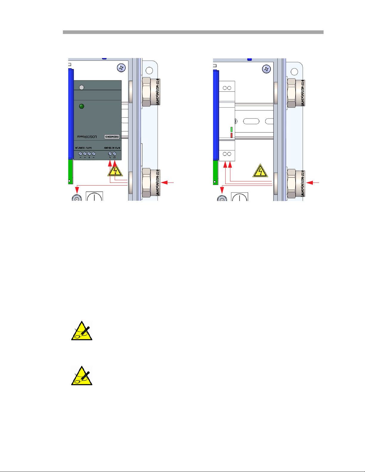
3. For AC systems, pull ground, neutral (N) and L1 wires into the
electronics enclosure. Refer to Figure 2–2.
For DC systems, pull VI +, – and ground wires into the electronics
enclosure. Refer to Figure 2–2.
4. Strip back the jacket and/or insulation of the wires just enough to
connect to the power terminal block.
5. Connect the main ground wire to the protection ground terminal
marked .
6. Close and tighten the analyzer enclosure door.
Apply 20 in-lbs of torque on each bolt to ensure the door is closed
properly to maintain required ingress protection.
2–6 4900002239 rev. G 3-4-16
DC LO
DC ON
Installation
N
AC POWER CONNECTION DC POWER CONNECTION
V1 + –
Figure 2–2 AC/DC power connections
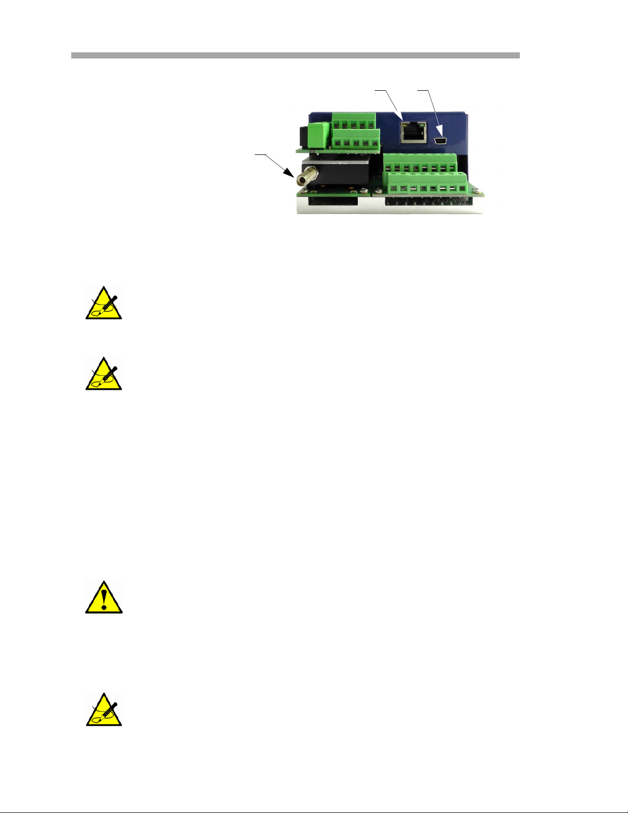
Analyzer Connections
The fiber optic oxygen cable to the SMA connector, located at the bottom of the
OXY5500, will be installed at the factory. Additional connectors are available as
shown in Figure 2–3.
RS-232/RS-485 Interface: The unit has standard RS-232
communication via Modbus protocol. Use care in making
connections as described in “Modbus Communication” on page
4-1 to avoid communication problems and potential damage to
the unit.
Optical Module with SMA Connector: The optical module with
SMA connector is used to connect to the oxygen probe, which is
installed at the factory.
OXY5500 Operator’s Manual 2
–7
Oxygen Analyzer
RJ-45
OPTICAL MODULE WITH
SMA CONNECTOR
Figure 2–3 Analyzer connections
USB Connection: The USB connection is for service and
troubleshooting purposes only. Do not connect during normal
operation. To avoid damage to the port, use only the USB Mini B
cable to connect to the unit.
Ethernet: The unit uses standard Modbus over Ethernet
communication. Use a CAT5 (or better) cable and make
connections per IEEE 802.3 standard.
USB
Connecting the Analog Outputs/Analog Inputs
The OXY5500 is equipped with two independent analog outputs and one analog
input. The 4-20 mA current loop and serial output are connected terminal
blocks located inside the analyzer electronics enclosure. By default, the 420mA current loop analog outputs (IOUT1/IOUT2) are set to inactive.
The analog outputs are programmable to oxygen and temperature. To allow
external data collection, one input port is available (i.e., external pressure
sensor).
A protective device (miniature circuit-breaker or circuit breaker)
and a disconnection unit for the power supply must be installed.
SpectraSensors recommends using a line-side miniature circuit
breaker (IEC 898): Characteristic B from 16 A or Characteristic C
from 10 A.
Connections can be made with customer-supplied cables for the current loop
and alarms. Consult the wiring diagram in Figure A–2 on page A–4.
Certified Ex e glands and cables, or conduit seal and conduit,
should be used where appropriate in compliance with local
regulations.
2–8 4900002239 rev. G 3-4-16
 Loading...