

Page 1

Drinking Water Kit with Non-Air Gap Faucet
for RO and RO/DI Systems
(Including “-MF” Systems)
Please read carefully before proceeding with installation. Failure to follow any
attached instructions or operating parameter may lead to the product’s failure and
®
SpectraPure
It is the user’s responsibility to determine that the system is leak-free.
v4 2013-12-03
Inc. assumes no responsibility for water damage due to leaks.
INSTRUCTIONS
WARNING
possible damage to property.
Page 2

SpectraPure
®
Thank You for your purchase of a
will provide you with high quality water for years to come. All SpectraPure® products are rigorously tested
by us for safety and reliability. If you have any questions or concerns, please contact our customer service
department at 1.800.685.2783 or refer to our online troubleshooting at www.spectrapure.com.
SpectraPure® System. With proper installation and maintenance, this system
TABLE OF CONTENTS
Operating Instructions
Feed water Requirements .................................................................................................................................. 3
Contents of DWK ................................................................................................................................................... 3
Configuring a Manual Flush (-MF) System For the Drinking Water Kit ............................................... 4
Configuring a Legacy (non -MF/-AF) System For the Drinking Water Kit ........................................... 5
Ice Maker Hookup (optional) ............................................................................................................................. 5
Diagram of RO/DI System With Drinking Water Kit Installed ................................................................. 6
Preparation .............................................................................................................................................................. 7
Feed Supply Valve Installation .......................................................................................................................... 8
Faucet Installation ................................................................................................................................................. 9
Drain Saddle Installation .................................................................................................................................. 10
Installing Pressurized Storage Tank and Mounting System .................................................................. 11
Startup Procedures ............................................................................................................................................. 11
Maintenance
Sanitizing the RO/DI System with DWK ...................................................................................................... 12
Recharging the Bladder Tank ......................................................................................................................... 12
Troubleshooting Guide
Troubleshooting for the Drinking Water Kits ...................................................................................... 13 -14
Warranty Information ..................................................................................................................................................... 15
Replacement & Optional Parts ..................................................................................................................................... 16
Copyright © 2013 by SpectraPure Inc.
ALL RIGHTS RESERVED
No part of this publication may be reproduced, stored in a retrieval system, or transmitted in any form or by any means,
electronic, mechanical, photocopying, recording or otherwise without the prior written permission of SpectraPure Inc.
2
SpectraPure®Inc.
480.894.5437 Call us toll-free 1.800.685.2783
2167 East Fifth St, Tempe, Arizona 85281
Page 3

SpectraPure
®
OPERATIONAL SPECIFICATIONS
RO Feed water requirements:
Operating Pressure: 40-80 psi (2.75-6.9 bar)
pH Range: 3-11
Maximum Temperature: 100°F (38°C)
Maximum Feed Turbidity: 1.0 NTU
Maximum Silt Density Index: 5.0 (based on 15 min. test time)
Maximum Chlorine: < 0.1 ppm
Maximum TDS: 1500 ppm
Maximum Hardness: 10 grains (170 ppm as CaCO3)
Maximum Iron: < 0.1 ppm
Maximum Manganese: < 0.1 ppm
Maximum Hydrogen Sulfide: 0 ppm
Langelier Saturation Index (LSI): must be negative
NOTE: MOST MUNICIPAL WATER SUPPLIES MEET THE ABOVE REQUIREMENTS. IF WELL WATER IS USED,
PLEASE MAKE SURE THAT YOU OBTAIN A WATER TEST BEFORE INSTALLATION.
NOTE: THE OPERATING PRESSURE IN YOUR HOME SHOULD BE TESTED OVER A 24 HOUR PERIOD TO OBTAIN
THE MAXIMUM PRESSURE. IF IT IS ABOVE 80 psi THEN A PRESSURE REGULATOR MAY BE REQUIRED.
CONTENTS OF DRINKING WATER KIT
DRINKING WATER ADD-ON KIT
(1) Pressurized Storage Tank (1) Inline Carbon Block w/ Push Fittings
(1) Faucet (with parts bag) (1) Feed Water Adapter
- (1) Galvanized Flange (1) Drain Saddle
- (1) Rubber Washer (1) Ball Valve, Right Angle (for the top of tank)
- (1) Flat Metal Washer with “U” Cutout (1) Automatic Shut-off Valve (ASO)
- (1) Plastic Spacer with Cutout (1) Ball Valve, (2) Check Valves
- (1) Flat Metal Washer (1) Tee (used to redirect RO water before the DI)
- (1) 3/8” Quick Connect Plastic Tubing Adapter
FEED WATER ADAPTER
RIGHT-ANGLE BALL VALVE
(FOR TANK)
2 - 1 lb. CHECK VALVES
REDUCTION TEE
2-WAY BALL VALVE
DRAIN SADDLE
(FOR WASTE TO DRAIN)
FAUCET
(FOR TAP LINE)
(1) Tee for Right-Angle Ball Valve
FAUCET
PARTS BAG
PRESSURIZED
STORAGE TANK
1/4" TEE
(USED TO TEE OFF DI
WATER FOR RO/DI
SYSTEMS)
IF ANY OF THE ITEMS LISTED ABOVE ARE MISSING PLEASE CONTACT SPECTRAPURE PRIOR TO INSTALLATION.
ALL RETURNS WITHOUT RMA# WILL BE REFUSED. CLAIMS MUST BE WITHIN 10 DAYS FROM RECEIPT.
FAUCET
ADAPTER
SpectraPure® Inc.
INLINE CARBON
BLOCK FILTER
480.894.5437 Call us toll-free 1.800.685.2783
2167 East Fifth St, Tempe, Arizona 85281
ASO VALVE
3
Page 4

SpectraPure
®
CONFIGURING A MANUAL FLUSH SYSTEM FOR THE DRINKING WATER KIT:
SpectraPure “-MF” Systems (MC-RODI-xx-MF, CSPDI-xx-MF, CSP-xx-MF) are configured in such a way as to be incompatible
with the Drinking Water Kit. Follow these steps to convert your “-MF” system into a compatible configuration.
THIS DOES NOT WORK WITH “-AF” SYSTEMS.
1. Disconnect the blue tube, the short yellow tube and the red (or green - whichever you chose during Setup) tube
from the ASO Valve. You should find the short Flow Restrictor inside the red (or green) tube.
2. Disconnect the black tube from the RO membrane housing. Reroute it from the center hole in the back of the bracket
to the left-hand hole (as viewed from behind). Measure 3 inches of black tube above the bracket and cut the black
tube in two. That black tube from the carbon block connects to the only IN port of the ASO.
3. The OUT port of the ASO now connects to the membrane housing input, using a newly-cut length of black tubing
supplied in the kit.
4. Cut the blue tube still connected to the membrane housing down so there is only 1 inch of tubing exposed. Connect
a 1/4" Check Valve to this blue tube with the arrow pointing away from the blue tube.
5. Cut a piece of blue tube down to 2 inches. Connect one end to the the remaining free end of the Check Valve and
the other end to the ASO Valve. (Note: the arrow should be pointed towards the ASO valve.)
6. Disconnect the short yellow tubing from the Y fitting that was once connected to the ASO valve.
7. Insert the red (or green) tube with the Flow Restrictor in that end into that Y fitting.
8. Cut the longer yellow tube that is still attached to the ball valve so that it, the ball valve, and the short yellow tube
matches the length of the red (or green) tube.
9. Reconnect the yellow and red (or green) tubes to the Y fitting. Now you are ready to hook up your drinking water
kit as it is shown in the following pages.
CORRECT CONFIGURATION OF MANUAL FLUSH AND
ASO AFTER CONVERSION FOR DRINKING WATER KIT
Waste
Water Port
Check Valve
IN port of ASO Valve
Membrane Housing
ASO Valve
OUT port of ASO Valve
CORRECT CONFIGURATION OF MANUAL FLUSH
AFTER CONVERSION FOR DRINKING WATER KIT
Stem Adaptor
4
SpectraPure®Inc.
Connect Yellow
Tubing to Drain
Flow Restrictor Inside
480.894.5437 Call us toll-free 1.800.685.2783
2167 East Fifth St, Tempe, Arizona 85281
Page 5

SpectraPure
®
CONFIGURING A LEGACY SYSTEM FOR THE DRINKING WATER KIT:
(Including MPRO, MPDI, CSP, CSPDI and MAXCAP models without automatic or manual flush)
1. Locate the Black Tube between the Carbon Filter and the Membrane.
2. Cut the Black Tube in two.
3. Insert the cut end from the Carbon Filter into the IN Port of the ASO Valve.
4. Insert the cut end from the RO Membrane Housing into the OUT Port of the ASO Valve.
5. Locate the Blue Tube (product water) that leaves the RO Membrane Housing.
6. Cut the Blue Tube 2” from the membrane housing.
7. Using the 1 lb Check Valve, reconnect the two cut ends with the arrow pointing away from the membrane.
8. Position the Blue Tube along side the ASO Valve to determine where the blue tube needs to be cut. Then cut the
blue tube and reconnect the two cut ends with the two remaining ports of the ASO Valve. (See Diagram on Page 6.)
ICE MAKER HOOKUP (OPTIONAL)
1. Turn off feed supply valve and the ball valve on tank.
2. Locate the Blue tube that leads to the faucet.
3. Cut the tube and reconnect the cut ends with a 3/8” x 3/8” x 1/4” Tee.
4. Connect 1/4” Tubing to the third leg of the tee and route to refrigerator.
5. Turn on feed supply valve and the ball valve on tank.
SpectraPure® Inc.
480.894.5437 Call us toll-free 1.800.685.2783
2167 East Fifth St, Tempe, Arizona 85281
5
Page 6

SpectraPure
®
“B”
RO/DI SYSTEM WITH DRINKING WATER KIT INSTALLED
“A”
FOR RO-ONLY SYSTEMS:
CONNECT ASO PORT “A” TO TANK TEE “B” .
(CHECK VALVE AND TEE NOT REQUIRED)
6
SpectraPure®Inc.
480.894.5437 Call us toll-free 1.800.685.2783
2167 East Fifth St, Tempe, Arizona 85281
Page 7

SpectraPure
®
PREPARATION
1. Prepare for installation by removing all items from under the sink. Locate and turn off the COLD water supply and
open the sink faucet to relieve any remaining pressure.
2. Determine an appropriate location for the Drinking Water System, Bladder Tank, Feed Water Connection, Drain
Saddle, and the Non -Air Gap Faucet for your specific application.
3. TOOLS RECOMMENDED FOR INSTALLATION:
- Adjustable Wrench
- Sharp Knife
- Open End Wrench
- Phillips Screw Driver
- Needle Nose Pliers- Adjustable Pliers
- Electric Drill
- 1/2" Hole Saw Bit for Faucet Opening (depends on faucet used)
- Round Knock out Punch for Stainless Sinks, 1/2"
DRILL HOLE FOR FAUCET IN A PORCELAIN SINK
NOTE: Porcelain sink material is extremely hard and can crack or chip quite easily. To avoid this, use extreme caution
when drilling. A carbide tipped masonry bit is recommended. SpectraPure® accepts no responsibility for
consequential damage resulting from the installation of the faucet.
STEP 1. Determine a desired location for the faucet on your sink and place a piece of masking tape on the location
where the hole is to be drilled. Mark the center of the hole on the tape.
STEP 2. Use a variable speed drill on the slowest speed. Drill a 1/8" Pilot hole through both porcelain and metal casing
of sink at the center of the desired location. (If drill bit gets hot it may cause the porcelain to crack or chip.)
STEP 3. Use a 1/2” hole saw and proceed to drill the large hole. Keep drill speed on the slowest speed and use lubricating
oil or liquid soap to keep the hole saw cool during cutting.
STEP 4. Make sure the surroundings of the sink are cooled before mounting the faucet to the sink after drilling. Remove
all sharp edges with a file.
PUNCH HOLE FOR FAUCET IN STAINLESS STEEL SINK
STEP 1. If mounting faucet to a Stainless Steel Sink you will need a bimetal or carbide tipped hole saw.
STEP 2. The Faucet opening should be centered between the back splash and the edge of the sink, ideally on the
same side as the vertical drain pipe.
STEP 3. Drill a 1/4” pilot hole. Use a bimetal or carbide tipped hole saw to punch the 1/2” hole in the sink.
SpectraPure® Inc.
480.894.5437 Call us toll-free 1.800.685.2783
2167 East Fifth St, Tempe, Arizona 85281
7
Page 8

SpectraPure
®
FEED SUPPLY VALVE INSTALLATION
STEP 1. Follow the cold water line from shut-off valve to the existing faucet and unscrew the threaded connection.
STEP 2. Insert feed supply valve between cold water line and existing connection.
STEP 3. Follow the assembly sequence shown for attaching valve to the existing cold water line.
STEP 4. Connect Black line from RO system as shown in Fig 1.
a. Remove the 1/2" Compression Nut from Valve body. Be carefull not to loose the plastic or brass Insert and
the Conical Compression Sleeve.
b. Insert the 1/4” Black Tubing into the Compression Nut with the threads towards the end of the tube.
c. Slip the Conical Compression Sleeve onto the Black Tube with the long slope pointing toward the end of
the tube.
d. Place the Insert into the end of the Black Tubing. Make sure you push the insert in all the way.
e. Tighten Compression Nut back on the Valve body.
STEP 5. When installation of the valve is complete, check for leaks as follows:
a. Close Feed Supply Valve that you just installed.
b. Open cold water supply valve and check for leaks around feed supply valve fittings. Tighten if necessary.
NOTE: To be certain of the cold line; turn on the hot water, allow water to run until pipe becomes warm. Then
attach fitting to the cold water line. If you run hot water through your system it will damage the membrane.
FEED VALVE
INSTALL ON COLD WATER LINE
8
SpectraPure®Inc.
FIGURE 1: FEED SUPPLY INSTALLATION
480.894.5437 Call us toll-free 1.800.685.2783
2167 East Fifth St, Tempe, Arizona 85281
Page 9

SpectraPure
®
FAUCET INSTALLATION
1. Place the chrome counter plate and large rubber washer over the threaded shaft on the faucet and insert this
assembly into hole previously drilled on page 7.
2. Place the small rubber washer, locating washer, flat metal washer, and hex nut in sequence over the threaded shaft
and temporarily hand-tighten. (Fig. 2)
3. Insert the Blue Tube into the Compression Nut with the threads towards the end of the tube. Then add the
Compression Sleeve.
4. Place the Insert into the end of the Blue Tubing. Make sure you push the insert in all the way. Screw the Compression
Nut onto the threaded shaft.
5. Securely tighten both hex nut and Compression Nut.
6. DO NOT CUT EXCESS TUBING AT THIS POINT. YOU WILL NEED THE TUBING TO INSTALL THE TANK.
TIP: When connecting the tubes to the hose barbs, try using HOT water to soften the plastic tubes. When connecting the
drain lines to the saddle, make the lengths as short and straight as possible to reduce drainage noise.
NON AIR-GAP FAUCET PARTS LIST
– Faucet
– Chrome Counter Plate
– Locating Washer
– Large Rubber Washer
– Small Rubber Washer
– Flat Metal Washer
– Hex Nut
– Plastic Conical Compression Sleeve
– Insert
– Compression Nut
Figure 2 Figure 3: INSTALLATION FOR TYPICAL 3-STAGE RO SYSTEM
SpectraPure® Inc.
2167 East Fifth St, Tempe, Arizona 85281
480.894.5437 Call us toll-free 1.800.685.2783
9
Page 10
SpectraPure
®
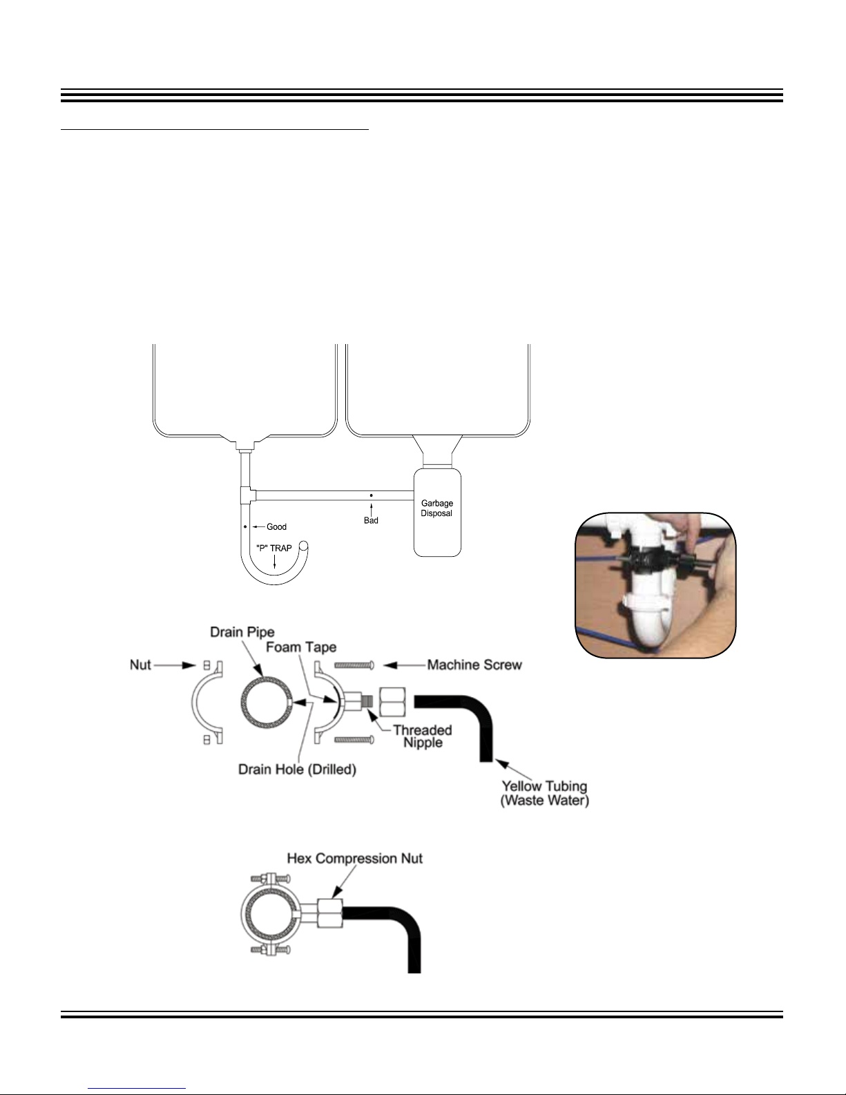
DRAIN SADDLE INSTALLATION
1. Refer to Figure 4 and determine the location for the drain saddle assembly and drain hole. It must be located above
the “P” trap (“U” shaped bend in drain pipe) on the sink side of the drain pipe.
2. Place the half of the drain saddle with threaded nipple at a predetermined location. Slide a pencil through the plastic
nipple and make a mark on the drain pipe.
3. Use a small punch and indent a start position to prevent the drill bit from wandering. Drill a 3/8" hole in the drain
pipe through the mark on one side only, do not drill through both sides of the drain pipe.
4. Clean any loose shavings from around the hole.
5. Refer to Figure 5 showing the drain saddle assembly sequence. Press nuts in back half of drain saddle assembly.
6. Align the front half of the drain saddle by inserting a pencil through the plastic nipple and the newly drilled hole in
the drain pipe.
7. Install the back half of the drain saddle and clamp assembly to drain pipe by screwing in the mounting bolts until snug.
Figure 4: Drain Saddle Mounting Locations
Figure 5: Drain Saddle Assembly Sequence
10
SpectraPure®Inc.
480.894.5437 Call us toll-free 1.800.685.2783
2167 East Fifth St, Tempe, Arizona 85281
Page 11

SpectraPure
®
INSTALLING BALL VALVE ON TANK
STEP 1. If there is not Teflon tape applied to the nipple on the tank, wrap (7-12 turns)
around the pipe threads (MPT) on the Stainless Steel fitting.
STEP 2. Thread the Ball Valve (supplied in the parts bag) onto the stainless steel nipple
on top of the tank. Hand tighten only.
NOTE: The storage tank is pressurized with air at the factory to 6 psi with the tank totally drained. Over a period of
time, air may leak out causing the delivery rate of the stored water to decrease. If this occurs, verify correct tank
pressure using a low pressure air gauge on the tire valve stem located on the bottom, or near the flange at the
top of the tank with tank completely empty of water and faucet opened.
Refer to operation and maintenance on page 12.
MOUNTING SYSTEMS INSTALLATION
STEP 1. Determine best location for the RO system to be
mounted to allow for future system maintenance.
Use two (2) self - tapping (or wood) screws and
a Phillips screwdriver. Measure the distance
between the key hole slots on the back of the
bracket and install screws . Leave enough space
and tubing so that you can pull the system out
for maintenance.
STARTUP PROCEDURES
1. Slowly turn the cold water supply to full flow. Check for leaks.
2. Turn the valve on the storage tank to the “OFF” position and open the faucet.
3. Watch the clear housings fill with water. When water comes out of the faucet, turn the faucet off. The system will
pressurize rapidly and should shut off with a “click”.
NOTE: It is important that air is purged from system during initial operation. To do this, orient the RO unit with the
product (permeate) and reject (brine) water ports pointing upwards. (Round end of RO membrane housing
is up, prefilter housings are horizontal). Allow a minimum of 10 minutes operation with this orientation.
4. Look for leaks and do not leave the system alone until you are sure there are no leaks. Now, turn the valve on
the tank to the “ON” position.
5. Before using the system, allow three tank fillings to occur, then flushing the contents between each filling by locking
the faucet lever to the open position until drained.
6. Wait for an hour before drawing water from of the faucet.
Note: NEVER RUN HOT WATER (>100°F) THROUGH THE SYSTEM.
SpectraPure® Inc.
480.894.5437 Call us toll-free 1.800.685.2783
2167 East Fifth St, Tempe, Arizona 85281
11
Page 12

SpectraPure
®
MAINTENANCE PROCEDURES
SANITIZING THE RO/DI SYSTEM WITH DWK
Sanitizing is recommended at least once every year or if water smells (or tastes) bad even after a post carbon filter
replacement. A convenient time for sanitization is during a filter changeout. IT IS IMPORTANT THAT YOU HAVE CLEAN
HANDS WHILE HANDLING INNER PARTS OF THE SYSTEM.
1. Be sure water supply to the RO/DI system is turned off, and the dispenser faucet is open. This will completely
drain the pressure tank. Block the water flow to drain by doubling-over the yellow tubing and secure with wire
or a “Ty-Rap”.
2. Next, remove the 1/4" black tubing from the feed port of the membrane and lift membrane housing from clips.
3. Remove the membrane housing cap by unscrewing it counterclockwise. Grasp the membrane stem with a pair
of pliers and pull the membrane from the housing.
4. Screw the cap back on to the membrane housing making sure that the o-rings are in place.
5. Reconnect the 1/4" black tubing to the feed port of the membrane.
6. Remove sediment, carbon block, deionization cartridge and in-line post carbon filter.
7. Put 1.5 - 2.0 oz. of household bleach in the left filter housing and fill it halfway with tap water. Now, put all filter
housings back on the bracket, keeping the one with the bleach on the left side.
8. Next, close the dispenser faucet (put lever in DOWN position).
9. Open feed supply valve 1/4 turn from closed position. Open the dispenser faucet.
10. Allow 15 minutes for the bleach solution to flow through the system. Then, open dispenser faucet and keep
the lever in the UP position until some bleach solution is dispensed through the faucet. IMMEDIATELY close the
faucet as soon as the bleach solution appears. This will sterilize the faucet and the line going to the faucet.
11. Let the system sit for 2 hours.
12. Open the dispenser faucet to drain bleach solution from the pressure tank as completely as possible and then
close the faucet.
13. Open the feed supply valve fully.
14. Allow the tank to fill until pressure gauge reaches 40 psi. Then open the dispenser faucet and flush system until
all bleach solution has been dispensed from the system.
15. Close the feed supply valve.
16. Remove filter housings and membrane housings from the system and then rinse them with tap water and drain
them completely.
17. Put new replacement filters (sediment filter, carbon block filter and inline post carbon filter) into the filter housings
and put the membrane back into the membrane housing. You can use the same deionization cartridge if the DI
cartridge has not been exhausted.
Open the feed supply valve and check for leaks. This completes the procedure.
RECHARGING THE BLADDER TANK
If the storage capacity of the tank is diminished significantly it is likely that the tank has lost its air charge. Recharging
the bladder tank will restore its capacity.
1. Be sure water supply to the RO/DI system is turned off, and the dispenser faucet is open (lever in up position).
2. Leave the faucet in the open position unil the procedure is completed.
3. Drain as much water as possible from the tank. If there is no air charge remaining, very little water will come out.
4. Connect an air pump to the “schrader” (tire) valve on the pressure tank and start pumping air into the tank.
5. Expel all the water from the tank.
6. Continue pumping air into the tank until the pressure reads NO MORE than 7 PSI.
7. This completes the procedure. Turn system back on.
NOTE: Should this procedure fail to restore the capacity of the tank, it is very likely that the bladder in the tank is
ruptured and the tank needs replacement.
12
SpectraPure®Inc.
480.894.5437 Call us toll-free 1.800.685.2783
2167 East Fifth St, Tempe, Arizona 85281
Page 13

SpectraPure
®
TROUBLESHOOTING GUIDE
Problem Cause Corrective Action
1. LOW PRODUCTION RATE
a. plugged prefilters. i. Replace prefilters.
b. low water temperature. ii. Use higher GPD membrane.
c. low water pressure (< 40 psi). iii. Use booster pump OR use higher GPD
membrane.
d. high TDS content (> 1000 ppm). iv. Use booster pump OR use higher GPD
membrane.
e. fouled membrane. v. Replace membrane.
f. plugged flow restrictor. vi. Replace flow restrictor & membrane.
g. tank bladder lost air charge. vii. Repressurize bladder to 7 psi (when empty).
h. too much pressure in bladder tank. viii. Repressure bladder to 7 psi (when empty).
i. ruptured bladder. ix. Replace tank.
j. back pressure exerted by the
pressurized bladder tank causes a
reduction in production rate.
2. ZERO PRODUCTION RATE
a. missing flow restrictor. i. Put flow restrictor in the yellow brine line.
b. dried membrane. ii. Replace membrane.
c. plugged flow restrictor. iii. Replace flow restrictor and membrane.
d. bladder lost air charge. iv. Repressurize bladder to 7 psi (when empty).
e. ruptured bladder. v. Replace tank.
3. EXTREMELY HIGH PRODUCTION RATE
a. Ruptured membrane. i. Replace it.
b. Very high line pressure (over 80 psi). ii. Use a pressure reducing valve.
x. Use of permeate pump retrofit kit (PPRFK-DI)
eliminates the back pressure.
SpectraPure® Inc.
(continued on next page)
480.894.5437 Call us toll-free 1.800.685.2783
2167 East Fifth St, Tempe, Arizona 85281
13
Page 14

SpectraPure
®
TROUBLESHOOTING GUIDE (continued)
Problem Cause Corrective Action
WATER SMELLS BAD.
4.
a. Bacterial contamination of bladder
tank.
b. Ruptured bladder in storage tank. ii. Replace tank.
c. Exhaused post carbon filter. iii. Replace post carbon filter.
MILKY COLORED WATER.
5.
a. Air in system. i. Air in the system is a normal occurrence with
REJECT (YELLOW) LINE NEVER STOPS FLOWING WATER.
6.
a. Faulty 1 lb. check valve. i. Replace it.
b. Faulty auto shut-off valve. ii. Replace it.
i. Sanitize RO/DI System.
intial startup of the RO/DI system. This milky
appearance will disappear during normal use
within 1-2 weeks. If condition recurs after filter
changes, drain tank 1 to 2 times.
NOISE FROM DRAIN.
7.
a. Location of drain saddle. i. See Figure 7 for proper location of drain
14
SpectraPure®Inc.
saddle.
480.894.5437 Call us toll-free 1.800.685.2783
2167 East Fifth St, Tempe, Arizona 85281
Page 15

SpectraPure
®
THREE YEAR LIMITED WARRANTY
All standard water purification products manufactured by SpectraPure have a 3 year limited warranty with
the exception of Industrial, Laboratory, Custom Systems and electrical products which have a 1 year limited
warranty. LiterMeters™ have a 5 year limited warranty. OEM equipment resold by SpectraPure carry the
original manufacturer’s warranty.
®
SpectraPure, Inc.
workmanship for a period of three years (see exceptions above) from the date of receipt. SpectraPure’s liability
under this warranty shall be limited to repairing or replacing at SpectraPure’s option, without charge, F.O.B.
SpectraPure’s factory, any product of SpectraPure’s manufacture. SpectraPure will not be liable for any cost
of removal, installation, transportation or any other charges which may arise in connection with a warranty
claim. Products which are sold but not manufactured by SpectraPure are subject to the warranty provided
by the manufacturer of said products and not by SpectraPure’s warranty. SpectraPure will not be liable for
damage or wear to products caused by abnormal operating conditions, accident, abuse, misuse, unauthorized
alteration or repair, products not installed in accordance with SpectraPure’s or other manufacture’s printed
installation and operating conditions, or damage caused by hot water, freezing, flood, fire or acts of God.
SpectraPure will not be responsible for any consequential damages arising from installation or use of the
product, including any water or mold damage due to flooding which may occur due to malfunction or faulty
installation, including, but not limited to failure by installer to over- or under-tighten fittings, housings, and/
or push-style fittings, or improper installation of push-style fittings.
warrants the product to the original owner only to be free of defects in material and
To obtain service under this warranty, the defective system or components must be returned to SpectraPure
with proof of purchase, installation date, failure date and supporting installation data. Any defective product
to be returned to the factory must be sent freight prepaid; documentation supporting the warranty claim
and a Return Merchandise Authorization (RMA) number must be included. SpectraPure will not be liable for
shipping damages due to the improper packaging of the returned equipment and all returned goods must
also have adequate insurance coverage and a tracking number.
SpectraPure will not pay for loss or damage caused directly or indirectly by the presence, growth, proliferation,
spread or any activity of “fungus”, wet or dry rot or bacteria. Such loss or damage is excluded regardless of
any other cause or event that contributes concurrently or in any sequence to the loss. We will not pay for loss
or damage caused by or resulting from continuous or repeated seepage or leakage of water, or the presence
or condensation of humidity, moisture or vapor, that occurs over time. “Fungus” and “fungi” mean any type
or form of fungus or Mycota or any by-product or type of infestation produced by such fungus or Mycota,
including but not limited to, mold, mildew, mycotoxins, spores, scents or any biogenic aerosols.
SpectraPure will not be liable for any incidental or consequential damages, losses or expenses arising from
installation, use, or any other causes. There are no expressed or implied warranties, including merchantability
or fitness for a particular purpose, which extend beyond those warranties described or referred to above.
* The three year limited warranty does not apply to consumable items, including but not limited to,
filters and cartridges unless specifically stated above.
SpectraPure® Inc.
480.894.5437 Call us toll-free 1.800.685.2783
2167 East Fifth St, Tempe, Arizona 85281
15
Page 16

SpectraPure
®
REPLACEMENT PARTS:
Part Number Part Description
CF-IN-10 -6JG 10" inline post carbon filter Polishes water and removes any taste
V-ASO-4JG ASO Valve Completely shuts off Product water and Waste water
V-CK- IL-1LB-4JG Check Valve Used in conjunction with the ASO Valve.
OPTIONAL PARTS:
Part Number Description
PPRFK-DI
BPLF- PS -115
BPHF- PS-115
V-PREG-0-125 -4GJ
TANK-SN03-4
TANK-SN04-4
Permeate Pump Retrofit Kit used for RO/DI systems
Booster pump kit for use with up to 25-60 GPD system
Booster pump kit for use with over 60 GPD systems
Pressure reducing valve (pressure regulator)
3 Gallon Pressurized Storage Tank
4 Gallon Pressurized storage Tank
16
SpectraPure®Inc.
480.894.5437 Call us toll-free 1.800.685.2783
2167 East Fifth St, Tempe, Arizona 85281
 Loading...