

Page 1

Coffee Lovers System
4-Stage Compact DWS-CLS-3™
and
5-Stage Deluxe DWS-CLS-4™
OPERATIONS MANUAL
RO Drinking Water System
for
Coffee Lovers
DWS-CLS Rev. 10-13-2005
Page 2

®
SpectraPure
TABLE OF CONTENTS
Warranty Information.......................................................................................................................................................................3
RO Feed Water Requirements...........................................................................................................................................3
What is Reverse Osmosis ?..............................................................................................................................................................4
What does the System do? .............................................................................................................................................................4
System Description ............................................................................................................................................................................5
System Specifications...............................................................................................................................................................6
Installation ............................................................................................................................................................................................7
Preparation.................................................................................................................................................................................7
Air-Gap Faucet Installation............................................................................................................................................. 8-10
Installation Instructions for Push Fittings....................................................................................................................... 11
Drain Saddle Installation ..................................................................................................................................................... 12
System Tubing Connections ..............................................................................................................................................13
Ice Maker Hook-up................................................................................................................................................................ 13
Measuring Product to Waste Ratio.....................................................................................................................................14-15
Maintenance..................................................................................................................................................................................... 16
RO Membrane Replacement .............................................................................................................................................16
Post-Filter Replacement ....................................................................................................................................................... 17
Recharging the Bladder Tank............................................................................................................................................17
Sanitizing DWS System ........................................................................................................................................................18
Troubleshooting Guide...........................................................................................................................................................19-22
Testing Membrane Quality .......................................................................................................................................................... 23
TERMS AND CONDITIONS OF SALE
1. Shipping charges on units or parts submitted to our facility for repair or replacement must be borne by the registered purchaser.
After repair or replacement, the factory will return the unit or part freight prepaid to the customer.
2. We assume no warranty liability in connection with our equipment other than as herein specified.
3. This warranty is in lieu of all other warranties expressed or implied, including warranties of fitness for a particular purpose.
4. We do not authorize any person or representative to assume for us any other oblligation on the sale of our equipment. This is
the exclusive remedy and liability for consequential damages under any and all warranties which are excluded to the extent
exclusion is permitted by law.
5. Proof of original purchase date must accompany all warranty claims.
6. SpectraPure, Inc. reserves the right to change prices without notice when necessary. All prices in the catalog are quoted in US
dollars.
7. Claims for error in quantity or condition must be made within 10 days of receipt of material. SpectraPure, Inc. will not be
responsible for any claimed shortages not reported within 10 days. Returns other than warranty claims may be subject to 20%
restocking fee.
8. SpectraPure, Inc. cannot be held liable for damage or loss to a shipment by a freight carrier. Check shipment for damage before
acceptance or note on freight bill subject to inspection for concealed damage. Consignee must file claim. SpectraPure, Inc. will
offer as much assistance as possible.
9. A complete credit check is required prior to shipping on a Net 30 or “C.O.D. - CUSTOMER CHECK ACCEPTABLE” basis. In the
interim period during which credit references are being evaluated, all orders must be shipped “C.O.D. - CERTIFIED FUNDS”
(cash, cashiers check or money order).
10. All returned checks (due to insufficients funds or closed accounts) will be subjected to a $25 penalty charge.
Invoices on Net 30 accounts not paid within 30 days of shipment will be considered delinquent and will accure
Finance charges at the rate of 1.5% per month (18% per annum).
SpectraPure®Inc.
2
480.894.5437 Call us toll-free 1.800.685.2783
2167 East Fifth St, Tempe, Arizona 85281
Page 3

®
SpectraPure
WARRANTY
THEE YEAR LIMITED WARRANTY
Effective on products purchased after March 10, 2005.
All standard water purification products manufactured by SpectraPure have a 3 year limited warranty, except the Eliminator™
MarinePro™, Industrial, Laboratory, Custom Systems, and electrical products which have a 1 year limited warranty. LiterMeters™ have a
2 year limited warranty. OEM equipment resold by SpectraPure carry the original manufacturer’s warranty.
SpectraPure, Inc.® warrants the product to the original owner only to be free of defects in material and workmanship for a period
of three years (see exceptions above) from the date of receipt. SpectraPure’s liability under this warranty shall be limited to repairing
or replacing at SpectraPure’s option, without charge, F.O.B. SpectraPure’s factory, any product of SpectraPure’s manufacture.
SpectraPure will not be liable for any cost of removal, installation, transportation or any other charges which may arise in connection
with a warranty claim. Products which are sold but not manufactured by SpectraPure are subject to the warranty provided by the
manufacturer of said products and not by SpectraPure’s warranty. SpectraPure will not be liable for damage or wear to products caused
by abnormal operating conditions, accident, abuse, misuse, unauthorized alteration or repair or, if the product was not installed in
accordance with SpectraPure’s or other manufacture’s printed installation and operating conditions, or damage caused by hot water,
freezing, flood, fire or acts of God.
SpectraPure will not be responsible for any consequential damages arising from installation or use of the product, including any water
or mold damage due to flooding which may occur due to malfunction or faulty installation, including, but not limited to failure by
installer to over- or under-tighten fittings, housings, and/or push-style fittings, or improper installation of push-style fittings.
SpectraPure warrants (pro-rated) the performance of tested SpectraSelect™ RO membrane elements only, for one year from date of
receipt by the buyer, providing that the loss of performance was not caused by fouling , neglect or water conditions exceeding the
feed water parameters listed in the applicable product manual (refer to detailed membrane warranty information). SpectraPure will, on
confirmation of loss of performance during the warranty period, credit the pro-rated amount of the current catalog price of the element.
The disposable filters and cartridges are not covered under the warranty.
To obtain service under this warranty, the defective system or components must be returned to SpectraPure with proof of purchase,
installation date, failure date and supporting installation data. Any defective product to be returned to the factory must be sent
freight prepaid; documentation supporting the warranty claim and a Return Goods Authorization (RGA) number must be included.
SpectraPure will not be liable for shipping damages due to the improper packaging of the returned equipment and all returned goods
must also have adequate insurance coverage and a tracking number.
SpectraPure will not pay for loss or damage caused directly or indirectly by the presence, growth, proliferation, spread or any activity
of “fungus”, wet or dry rot or bacterica. Such loss or damage is excluded regardless of any other cause or event that contributes
concurrently or in any sequence to the loss. We will not pay for loss or damage caused by or resulting from continuous or repeated
seepage or leakage of water, or the presence or condensation of humidity, moisture or vapor, that occurs over a period of 14 days or
more. “Fungus” and “fungi” mean any type or form of fungus or Mycota or any by-product or type of infestation produced by such
fungus or Mycota, including but not limited to, mold, mildew, mycotoxins, spores, scents or any biogenic aerosols.
SpectraPure will not be liable for any incidental or consequential damages, losses or expenses arising from installation, use, or any
other causes. There are no expressed or implied warranties, including merchantability or fitness for a particular purpose, which extend
beyond those warranties described or referred to above.
* The three year limited warranty does not apply to consumable items, including but not limited to, filters and cartridges unless
specifically stated above
RO Feed water requirements*
• Operating Pressure: 40-80 psi (2.75-6.9 bar).
• pH Range: 3-11.
• Max. Temperature: 100°F (38°C).
• Max. Feed Turbidity: 1.0 NTU.
• Max. Silt Density Index: 5.0 (based on 15 min. test time).
• Maximum Chlorine: < 0.1 ppm
• Maximum TDS: 2000 ppm.
• Maximum Hardness: 10 grains (170 ppm as CaCO
• Maximum Iron: < 0.1 ppm.
• Maximum Manganese: < 0.1 ppm
• Maximum Hydrogen Sulfide: 0 ppm.
• Langlier Saturation Index (LSI): must be negative.
Most municipal water supplies meet the above requirements.
SpectraPure®Inc.
3
2167 East Fifth St, Tempe, Arizona 85281
480.894.5437 Call us toll-free 1.800.685.2783
).
3
Page 4

®
SpectraPure
WHAT IS RO?
WHAT IS REVERSE OSMOSIS
Osmosis is a process in nature that allows fluid of a lower concentration to pass through a semi-permeable membrane
into a fluid of a higher concentration (See Figure 1). Because of the difference in salt concentration, pure water flows
through the membrane as though a pressure were being applied to it (Figure 2). The effective driving force is called the
osmotic pressure. As a rough guide, the osmotic pressure is equal to about 1 psi (pounds per square inch) per 100 ppm
Total Dissolved Solids (TDS). When enough pressure is applied to the solution with a higher concentration it can then pass
through the membrane into the solution of lower concentration. (See Figure 3). This is the basis of Reverse Osmosis.
Figure 1
Household water pressure is used to force tap water through the semipermeable R.O. membrane. The membrane only
allows the purest of water molecules to pass through it while over 98% of most salts and other impurities are rejected and
automatically rinsed from the membrane down the drain.
Figure 2
Figure 3
WHAT DOES THE SYSTEM DO?
SpectraPure’s Coffee Lovers System uses household water pressure to reverse a natural physical process called osmosis.
Water, under pressure is forced through a semi-permeable membrane where minerals and impurites are screened out
and sent down the drain with waste water. These minerals and impurities are measured as total dissolved solids (TDS).
SpectraPure’s Coffee Lovers System uses a Patented Dual Pass TM Technology that controls the pH and mineral content to
levels optimized for perfect brewing (and drinking).
The undersink system connects to a house COLD water pipe for a water supply. The system includes replaceable sediment
and/or carbon pre-filters and a post carbon filter. The optional sediment pre-filter removes sand, dirt, rust particles and
other particulates while the carbon pre-filter takes chlorine and organics out of the feed water. The water then passes
through the RO membrane, through the post-carbon filter and the StablePureTM Re-minerization filter before being
stored in the pressurized tank. The storage tank holds almost 4 gallons (10 gallons optional) of once treated RO product
water. When water is called for, the water stored in the tank passes through the carbon post-filter and the Stable Pure Reminerization filter AGAIN before being delivered. A built-in auto shut-off valve will shut the system off when the tank is full.
The system also uses a permeate pump which reduces water waste by 80% over other traditional systems.
The Coffee Lovers system gives you a continous supply of sparkling clear, delicious water for drinking, cooking, coffeemaking etc. Foods will look better and taste better too. The carful control of pH and water hardness at proper levels is also
necessary to ensure your expensive brewing equipment is not corroded (low pH) or clogged (excessive mineral content).
Thus reliability with the Coffee Lovers TM Water Treatment System is greatly improved over other systems and costly
maintenance is avoided. The system eliminates the need to buy bottled water. Instead, it puts high quality water at your
fingertips.
SpectraPure®Inc.
4
480.894.5437 Call us toll-free 1.800.685.2783
2167 East Fifth St, Tempe, Arizona 85281
Page 5

®
SpectraPure
SYSTEM DESCRIPTION
SYSTEM DESCRIPTION
Coffee Lovers System TM (CLS) is a four or five stage reverse osmosis drinking water system.
The incoming feed water from cold supply pipe valve is directed through 1/4” tubing and is first passed
through an optional 0.5 micron Micro-Tec TM sediment pre-filter. This filter is used to remove excessive
turbidity, sand, dust, silt etc.that may cause the carbon filter to plug up. The next stage of filtration is a 0.5
carbon block pre-filter. This filter is used to remove organics and chlorine from the feed water that can damage
the membrane. The final stage of the system is the R.O. membrane. A high rejection Thin Film Composite (TFC)
membrane is used in this system. This removes over 98% of most inorganic salts, all micro-organisms and almost
all high molecular weight organics in the water. DualPass TM technology post-processes the RO water twice
for proper taste and hardness.
Pressure Gauge - The pressure gauge will alert you when it is time to change the sediment and the carbon prefilters.
Faucet - The sinktop or countertop faucet dispenses the drinking water. It has a hand operated, spring loaded
lever to keep the faucet closed and to prevent waste. You can keep the faucet open by pushing upward on
the lever and locking it against the spout. To meet plumbing codes, an air-gap is built into the faucet drain
water tubes. The air-gap prevents a back siphon of drain water.
Automatic Shutoff - When the pressurized storage tank has filled with product water, this valve automatically
shuts off feed water flow to the membrane and resumes flow to the membrane when the pressure tank is half
emptied.
Check valve - A check valve is built into the product water outlet of the RO housing. The check valve prevents
a backward flow of product water from the pressurzied storage tank to the membrane. A backward flow could
rupture the membrane.
Sump Kit (Optional) - An optional sump kit can be added to the DWS System enabling you to fill an open
reservoir with pure water for aquarium, hydroponics or other uses.
Permeate Pump - Most ordinary RO drinking water systems needlessly waste huge quantities of water.
SpectraPure’s drinking water systems with Permeate Pump provides a solution with the introduction of the
non-electric permeate pump. The permeate pump can reduce waste water by 80% compared to conventional
RO drinking water systems. Additonal advantages include longer membrane life, greatly improved water
quality, tank refills in half the time, greater holding capacity, and extended low line pressure operation.
Re-Mineralization Cartridge - Reintroduces certain minerals to the RO water to provide a pH-balanced
and better-tasting water especially suited for brewing coffee and tea.
SpectraPure®Inc.
5
480.894.5437 Call us toll-free 1.800.685.2783
2167 East Fifth St, Tempe, Arizona 85281
Page 6

®
SpectraPure
SYSTEM SPECIFICATIONS
SYSTEM SPECIFICATIONS
• (Optional) Sediment Pre-filter: 0.5 micron micro-tec sediment pre-filter
• Carbon Filter: 0.5 micron carbon block pre-filter
• Membrane Type: Thin film composite (TFC)
• Membrane Rejection Rate: 98% Average
• Membrane Production Rate: Rated GPD at 500 ppm TDS, 60 psi line pressure and 77°F (25°C) water
temperature.
• Postfilters: - 64 cu.in. granulated carbon filter.
- StablePure TM Re-mineralization Cartridge.
System Features
• pre-tested high rejection & high flow TFC membrane
• high efficiency pre-filters and post filter
• StablePure TM patented DualPass TM technology
• pressure gauge
• permeate pump (non electric)
• filter wrench
• code-approved air gap faucet
• automatic shut-off valve
• 4 gal. pressurized storage tank (10 gal. tank optional)
• compact, complete and pre-assembled
• easy to troubleshoot
• sump kit - SK - allows separate lines to aquarium, open reservoir etc. (Optional)
System Characteristics
• removes over 98% of most ionic impurities
• removes over 95% of organic impurities
• removes colloidal and particulate impurities
• removes all micro-organisms and pyrogens
• removes chlorine, chloramines, pesticides etc.
• reduce waste water by 80%
• pH and mineral content controlled for optimum drinking / brewing taste and increased equimpment
longevity.
SpectraPure®Inc.
6
480.894.5437 Call us toll-free 1.800.685.2783
2167 East Fifth St, Tempe, Arizona 85281
Page 7

®
SpectraPure
INSTALLATION
INSTALLATION
Preparation
Prepare area for installation by removing all items from under the sink. Locate and turn off cold water
1.
supply and open faucet to relieve any remaining pressure.
2. Look at typical undersink installation diagram in Figure 6. Determine appropriate location for DWS system,
bladder tank, feed water connection, drain connection and air gap faucet for your specific application.
3. Locate and close the cold water shut-off valve.
4. Follow the cold water line from shut-off valve to the existing faucet and unscrew the threaded connection.
Insert feed supply valve between cold water line and existing connection. Refer to Figure 4 and follow the
assembly sequence shown for attaching valve to the existing cold water line. When installation of the valve
is complete, check for leaks as follows:
a. Close feed supply valve.
b. Open cold water supply valve and check for leaks around feed supply valve fittings. Tighten
if necessary.
Note: To be certain of the cold line; turn on the hot water, allow water to run until pipe becomes warm. Then
attach fitting to the cold water line. If you run hot water through your system it will damage the membrane.
SpectraPure®Inc.
7
Figure 4
480.894.5437 Call us toll-free 1.800.685.2783
2167 East Fifth St, Tempe, Arizona 85281
Page 8

®
SpectraPure
INSTALLATION continued
AIR-GAP FAUCET INSTALLATION
1. Drill hole for air-gap faucet:
a. Determine the desired location to drill a 7/8” inch hole for the air gap faucet. Make certain ample
clearance exists and there are no obstructions in the form of reinforcement ribs, mounting hardware,
brackets, etc., that block or restrict access to the bottom of the faucet.
b. Once the hole location has been determined, use a small punch and indent a start position to
prevent the drill bit from wandering. Before drilling any holes, be certain to wear eye protection in the form
of safety glasses. Choose the appropiate drill bit for the type of sink on which the faucet will be mounted.
Note: For porcelain, a carbide tipped masonary bit is recommended. On stainless steel sinks, use a bimetal or
carbide tipped hole saw.
For any drilling operation, ensure the bits are sharp, and an adequately sized drill motor is used.
Note: If you are uncomfortable with this part of the installation, seek assistance from a plumber or other
qualified trade professional.
2. Air gap faucet assembly & installation:
a. Place the chrome flange and rubber washer over the threaded shaft and barbed nipples on
the faucet (Refer to Figure 5).
b. Get under the sink and place the flat metal washer (with “U” shaped cutout), plastic spacer, flat
washer, and hex nut in sequence over the threaded shaft of the non air gap faucet. Position the
air gap faucet for desired use and securely tighten the hex nut.
3. Screw 3/8” plastic adapter on the threaded shaft of the air gap faucet and tighten securely by hand.
(DO NOT OVER TIGHTEN PLASTIC FITTINGS).
SpectraPure®Inc.
8
Figure 5
480.894.5437 Call us toll-free 1.800.685.2783
2167 East Fifth St, Tempe, Arizona 85281
Page 9

SpectraPure
®
Figure 6-A : Typical Under Sink Installation for Compact Coffee Lovers System
SpectraPure®Inc.
9
480.894.5437 Call us toll-free 1.800.685.2783
2167 East Fifth St, Tempe, Arizona 85281
Page 10
SpectraPure
®
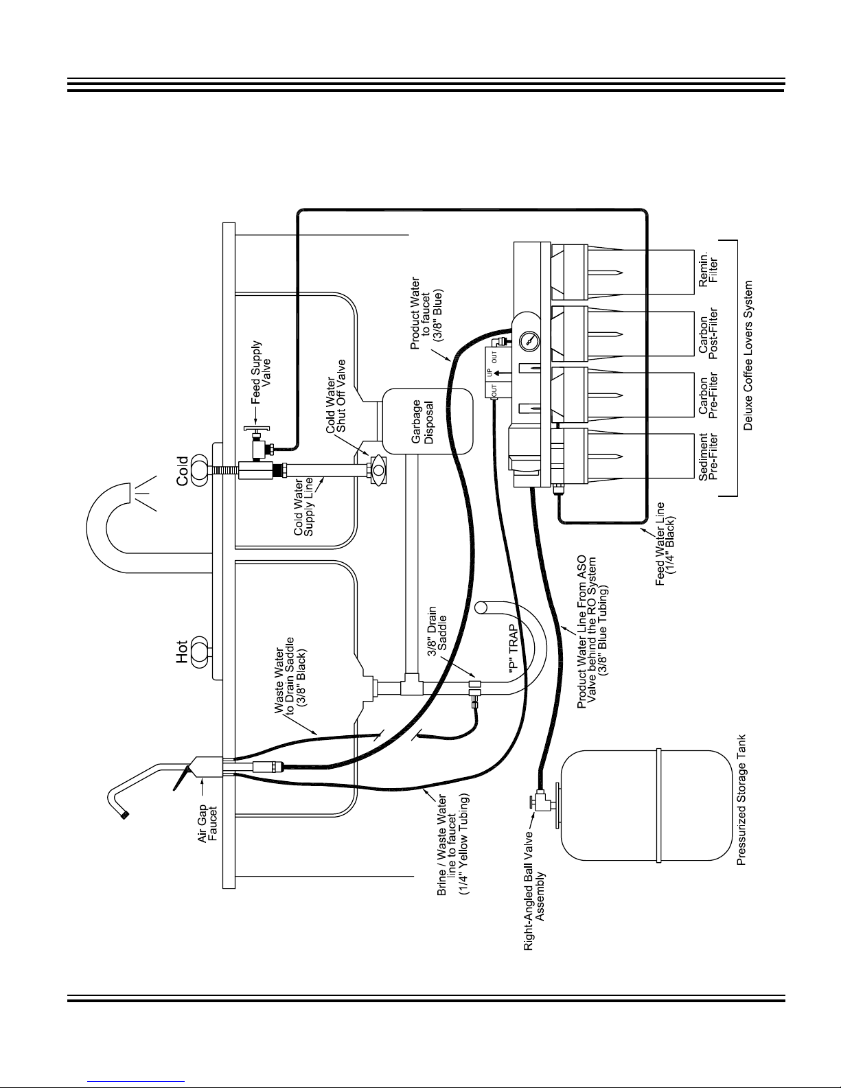
Figure 6B: System Schematic for Deluxe Coffee Lovers System.
SpectraPure®Inc.
10
480.894.5437 Call us toll-free 1.800.685.2783
2167 East Fifth St, Tempe, Arizona 85281
Page 11

®
SpectraPure
INSTALLATION continued
INSTRUCTIONS FOR PUSH-TYPE FITTINGS
1. Remove the tubing from its push-fitting as follows: (shown in Figure 7)
a.) Firmly depress and hold the push-fitting collette down with your thumbnail.
b.) While the push-fitting collar is depressed, pull the tubing straight out of the push-
fitting. Once the tubing is removed, release the collar.
2. Re-insert the tubing into its push-fitting as follows: (shown in Figure 7)
a.) Moisten the O-ring seal inside the fitting by dripping a few drops
of clean water onto the fitting.
b.) Grasp the tubing near its end, and insert the tubing into the push-fitting. Push
the tubing into the fitting until resistance is felt, approximately 1/2 inch (12.7 mm). The tubing is
now resting on the O-ring seal inside the fitting.
c.) Firmly push the tubing approximately an additional 1/4 inch (6.35 mm) further into
the fitting to completely seat the line into the fitting and O-ring seal.
11
SpectraPure®Inc.
2167 East Fifth St, Tempe, Arizona 85281
Figure 7
480.894.5437 Call us toll-free 1.800.685.2783
Page 12

®
SpectraPure
INSTALLATION continued
DRAIN SADDLE INSTALLATION
Refer to Figure 8A and determine the location for the drain saddle assembly and drain hole. It must be located above
the “P” trap (“U” shaped bend in drain pipe) preferably on the sink side of the drain pipe. Place the half of the drain
saddle with threaded nipple at a pre-determined location. Slide a pencil through the plastic nipple and make a mark
on the drain pipe. Use a small punch and indent a start position to prevent the drill bit from wandering. Drill a 3/8”
hole in the drain pipe through the mark on one side only, do not drill through both sides of the drain pipe. Clean any
loose shavings from around the hole.
Refer to Figure 8B showing the drain saddle assembly sequence. Press nuts in back half of drain saddle assembly. Align the
front half of the drain saddle by inserting a pencil through the plastic nipple and the newly drilled hole in the drain pipe.
Install the back half of the drain saddle and clamp assembly to drain pipe by screwing in the mounting bolts until snug.
Figure 8A: Drain Saddle Mounting Locations
Figure 8B: Drain Saddle Assembly Sequence
SpectraPure®Inc.
12
480.894.5437 Call us toll-free 1.800.685.2783
2167 East Fifth St, Tempe, Arizona 85281
Page 13

®
SpectraPure
INSTALLATION continued
SYSTEM TUBING CONNECTIONS
1. Using a length of the 3/8” blue tubing, check to make sure end of tubing is cut square. Insert one end into the 3/8”
plastic adapter on the air gap faucet. Push it into the adapter until it bottoms out, then pull down on the tubing to
lock it in place. Route the free end of the blue 3/8” tubing from the air gap faucet to the 3/8” tee behind the post
carbon filter housing. (Refer to Figure 9).
2. Screw the right-angled tank ball valve assembly onto the pressure tank and route the 3/8” blue product water tubing
from the 3/8” “T” behind the left-most filter to the tank valve.
3. Route 3/8” black tubing from barbed nipple on air gap faucet to drain saddle. Make this length as direct as possible
with no dips, then cut with sharp knife or razor. Remove hex compression nut from drain saddle, slip over the tubing,
then insert tubing in drain saddle until bottomed and tighten nut securely.
4. Slip the compression nut into the end of the 1/4” black feed water tubing from the RO system. Next, slip the conical
plastic compression sleeve over the same end. Make certain the taper on the compression sleeve faces the Feed
Supply Valve. Press the insert into the end of the tube. Place the tubing into the Feed Supply Valve until bottomed,
then tighten the hex compression nut securely with a 1/2” wrench.
5. Make sure all connections are tight, turn water on at Feed Supply Valve and watch for leaks. Tighten connections as
necessary if leaks occur.
6. NOTE: The storage tank is pressurized with air at the factory to 6 psi with the tank totally drained. Over a period of
time, air may bleed out causing the delivery rate of the stored water to decrease. If this occurs, verify correct tank
pressure using a low pressure air gauge on the tire valve stem located on the bottom of the tank with the tank
completely empty of water.
7. Refer to operation and maintainence sections of the manual.
Ice Maker Hook-Up (Optional)
1. Turn off feed supply valve and the ball valve on tank.
2. Locate the 3/8” Blue tube that leads to the faucet.
3. Cut the tube and reconnect the cut ends with a 3/8” x 3/8” x 1/4” Tee.
4. Connect 1/4” Tubing to the third leg of the tee and rotate to refrigerator.
5. Turn on feed supply valve and the ball valve.
This completes installation for the Ice Maker.
OPERATING INSTRUCTION
Operating the DWS system
1. Slowly turn the cold water supply to full flow.
Note 1: Wait for an hour before drawing water from of the faucet.
Note 2: It is recommended that at least 3 full tanks of purified water be discarded before using.
Note 3: Never run hot water (>100°F) through the system.
2. Waste water to product water ratio should be at least 4:1. This ratio is pre-set at the factory and should not require
adjustment until membrane is replaced.
3. It may require adjustment if any of the following conditions exist:
a. Extremely hard water (> 15 grains hardness).
b. Very warm water temperatures (> 80 °F water temperatures).
c. Line pressure outside of 50-70 psi range. If line pressure is over 80 psi, a pressure regulator. Please
contact the factory.
4. NOTE: It is important that air is bled from the system during initial operation. To do this, orient the RO unit with the
product (permeate) and reject (brine) water ports facing upwards. (Round end of RO membrane housing is up, prefilter housings are horizontal). Allow a minimum of 15 minutes operation with this orientation.
5. Before using the system, allow three tank fillings to occur, then flushing the contents by locking the air gap faucet
lever to the open position until drained.
SpectraPure®Inc.
13
480.894.5437 Call us toll-free 1.800.685.2783
2167 East Fifth St, Tempe, Arizona 85281
Page 14

SpectraPure
®
Figure 9: System Schematic for Coffee Lovers System with Air-Gap Faucet
SpectraPure®Inc.
14
480.894.5437 Call us toll-free 1.800.685.2783
2167 East Fifth St, Tempe, Arizona 85281
Page 15

®
FR-90
SpectraPure
PROCEDURE FOR WASTE TO PRODUCT RATIO
PROCEDURE FOR MEASURING WASTE TO PRODUCT WATER RATIO
This procedure will assure you of maximum life and reliability of your SpectraPure System. Failure to perform this proce-
dure can permanently damage the membrane and will void the pro-rated Membrane Warranty.
In order to maximize the life of your SpectraPure RO Membrane, you may need to adjust the ratio of the concentrate to
purified water. If not enough concentrate is allowed to flow past the membrane during operation, the impurities will
precipitate out on the membrane surface, clogging the RO Membrane. To keep this from happening, the Concentrate to
Purified Water Ratio must be checked and adjusted in order to compensate for pressure and temperature variations that
exist in all water supplies. The flow rate of the concentrate must be a minimum of 4X the product flow rate. 4X to 6X is an
acceptable concentrate flow rate.
Procedure:
1. Turn off the feed supply valve.
2. Turn the right-angle ball valve on the top of the pressure tank to the off position.
3. Disconnect the blue line from the tank.
4. Disconnect the black line from the drain saddle. (See figure 9)
5. Open the cold water supply valve and let the system run for 15 minutes. Direct both tubes down the
drain.
6. Collect product water from the blue tubing into a measuring cup for one minutes. Measure the collected amount
in milli-liters. Do the same with the waste from the yellow line.
WASTE (YELLOW) IN MILILITERS______________
DIVIDED BY
PRODUCT (BLUE) IN MILILITERS______________
The resultant is the Concentrate to Product Ratio
(Although not needed in this proceedure, the daily product flow rate in Gallons per Day (GPD) can be calculated to be
equal to the product flow rate times 0.38 ).
7. If ratio is less than 4:1
Disconnect yellow drain line from the membrane housing and then remove flow restrictor. Use
Waste to Product ratio chart in your system’s installation guide to determine where to cut the flow
restrictor in order to obtain a 4:1 ratio. (FR-90 Chart)
8. If ratio is greater than 6:1, flow restrictor requires replacement (Please contact SpectraPure Inc).
9. Turn the right-angled ball valve on the top of the pressure tank to the ON position.
10. Reconnect the 1/4” yellow drain line to the drain saddle. Turn on feed supply.
11. This completes the procedure.
PRODUCT RATE CUT TO LENGTH
ml./min. gpd
269 102 1 2.5
233 88 2 5.1
213 81 3 7.6
198 75 4 10.2
183 69 5 12.7
175 67 6 15.2
164 62 7 17.8
154 58 8 20.3
148 56 9 22.9
141 54 10 25.4
136 52 11 27.9
133 50 12 30.5
129 49 13 33.0
128 48 14 35.6
124 47 15 38.1
124 47 16 40.6
(Yellow)
in. cm.
SpectraPure®Inc.
15
480.894.5437 Call us toll-free 1.800.685.2783
2167 East Fifth St, Tempe, Arizona 85281
Page 16

®
SpectraPure
MAINTENANCE
MAINTENANCE
For maximum contaminant removal and long membrane life, the sediment and carbon pre-filters should be changed at
6-month intervals. If your water contains a great deal of sediment or chlorine, the pre-filters might have to be changed at
more frequent intervals to maintain an adequate production rate.
Sediment pre-filter and Carbon block pre-filter Replacement
Maintenance Regime: 15-20% drop in pressure OR at least once in 6 months OR when chlorine
breakthrough occurs.
Materials Needed: 0.5 micron micro-tec sediment pre-filter, 0.5 micron carbon block pre-filter, filter wrench.
Procedure:
1. Shut off feed supply valve and allow pressure to bleed down.
2. Remove the filter housings from their caps by unscrewing them clockwise as viewed from top or side. A filter wrench
may be needed.
3. Discard old filters.
4. Thoroughly wash out the housings with hot soapy water to which a few teaspoons of household bleach have been
added, and rinse well with clean hot water.
5. Install the new sediment pre-filter ( for the Deluxe System Only) in the left most housing, check to see if O-ring is
positioned in its groove and firmly tighten housing.
6. Install carbon block pre-filter in appropriate housing making sure, O-ring and black gaskets are in place. Hand tighten
housing.
7. Turn feed supply valve and check for leaks.
RO membrane Replacement
Maintenance Regime: As needed (Refer to procedure for testing membrane quality on page 23).
Materials Needed: Replacement TFC membrane, pliers.
Procedure:
1. Shut off feed supply valve to the DWS System and wait until pressure is relieved from the housing.
2. Next, remove the short 1/4” black tubing from the input elbow of the membrane and lift the membrane housing
from the clips.
3. Unscrew the RO housing lid counterclockwise from base.
4. With a pair of pliers, grasp the membrane stem and pull the membrane from the housing.
5. Wash housing with soapy water and rinse thorougly with hot clean water.
6. Insert new membrane into the housing, with the o-ring end first. The o-ringed tube must fit into the recess at the
bottom of the RO housing. When the membrane is aligned with the hole, push the membrane into the hole until it
bottoms out.
7. Replace housing o-ring on the housing rim and carefully screw the lid back on to the base.
8. Reconnect the 1/4” black tubing to the input elbow of the membrane.
9. Disconnect the yellow drain line from the membrane housing and remove the flow restrictor from the end of the
yellow tubing and reconnect the yellow tubing without the flow restrictor to the membrane housing.
10. Turn on feed supply valve to the DWS System. Flush the membrane and membrane housing for 10 minutes.
11. Turn off the water supply to the System. Remove the yellow drain line from the membrane housing and replace the
flow restrictor in the yellow line.
12. Reconnect the yellow drain line with the flow restrictor to the membrane housing, turn water supply on and check
for leaks.
13. Check ratio of waste water to product water. It should be at least 4: 1. If it is not 4:1, check the flow restrictor for
particle plugging or adjust ratio to 4:1.
SpectraPure®Inc.
16
480.894.5437 Call us toll-free 1.800.685.2783
2167 East Fifth St, Tempe, Arizona 85281
Page 17

®
SpectraPure
MAINTENANCE continued
Post-filter Replacement
Maintenance Regime: At least once in 12 months or whenever odor or bad taste occurs.
Materials Needed: Replacement Carbon Post-Flter.
Procedure:
1. Turn off feed supply valve and tank shut-off valve.
2. Remove the filter housing from its cap by unscrewing it clockwise as viewed from the top or side.
3. Discard old filter.
4. Thoroughly wash out the housing with hot soapy water to which a few teaspoons of household bleach have been
added, and rinse well with clean hot water.
5. Install the new post-filter.
6. Turn on both tank shut-off valve and feed supply valve. (Check for leaks)
Re-Mineralization Cartridge Replacement
Maintenance Regime: At least once in 12 months or whenever more than 50% of the minerals are exhausted.
Materials Needed: Replacement StablePure
Procedure:
1. Turn off feed supply valve and tank shut-off valve.
2. Remove the filter housing from its cap by unscrewing it clockwise as viewed from the top or side.
3. Discard old cartridge.
4. Thoroughly wash out the housing with hot soapy water to which a few teaspoons of household bleach have been
added, and rinse well with clean hot water.
5. Install the new cartridge.
6. Turn on both tank shut-off valve and feed supply valve. (Check for leaks)
TM Re-Mineralization Cartridge
Recharging the bladder tank
If the storage capacity of the tank is diminished significantly it is likely that the tank has lost its air charge. Recharging the
bladder tank will restore its capacity.
1. Put the dispenser faucet in the “open” position (lever in up position). Leave the faucet in the open position till the
procedure is completed.
2. Drain as much water as possible from the tank.
3. Hook up an air pump to the “Schrader” (tire) valve on the pressure tank and start pumping air into the tank.
4. Expel all the water from the tank.
5. Continue pumping air into the tank until the pressure reads 6 psi.
6. This completes the procedure.
Note: Should this procedure fail to restore the capacity of the tank, it is very likely that the bladder in the tank is ruptured
and the tank needs replacement.
SpectraPure®Inc.
17
480.894.5437 Call us toll-free 1.800.685.2783
2167 East Fifth St, Tempe, Arizona 85281
Page 18

®
SpectraPure
MAINTENANCE continued
SANITIZING THE DRINKING WATER SYSTEMS
Sanitizing is recommended at least once every year or if water smells (or tastes) bad even after a post carbon
filter replacement. A convenient time for sanitization is during a filter change-out. IT IS IMPORTANT THAT YOU
HAVE CLEAN HANDS WHILE HANDLING INNER PARTS OF THE SYSTEM.
1. Be sure water supply to the RO system is turned off, and the dispenser faucet is open. This will completely
drain the pressure tank.
2. Remove the post carbon filter and the remineralization filter from the system.
3. Put 1.5 - 2.0 oz. of household bleach in the right filter housing and fill it half-way with tap water.
4. Next, close the dispenser faucet (put lever in DOWN position).
5. Open the feed supply valve.
6. Allow 10 minutes for the bleach solution to flow through the system and into the storage tank.
7. Open dispenser faucet and keep the lever in the UP position till some bleach solution is dispensed through
the faucet. IMMEDIATELY close the faucet as soon as the bleach solution is detected. This will sterilize the
faucet and the line going to the faucet.
8. Let the system sit for 2 hours.
9. Open the dispenser faucet to drain bleach solution from the pressure tank as completely as possible and
then close the faucet.
10. Open the feed supply valve fully.
11. Allow the tank to fill until pressure gauge reaches at least 40 psi. Then open the dispenser faucet and flush
system until all bleach solution has been dispensed from the system.
12. Close the feed supply valve.
13. Remove post-filter housings from the system and then rinse them with tap water and drain completely.
14. Install new post-carbon and remineralization filters and hand tighten the housings.
15. Open the feed supply valve and check for leaks. This completes the procedure.
NOTE: Do not use filter wrench to tighten housings. Over-tightening will damage housings and void
your warranty.
SpectraPure®Inc.
18
480.894.5437 Call us toll-free 1.800.685.2783
2167 East Fifth St, Tempe, Arizona 85281
Page 19

®
SpectraPure
TROUBLESHOOTING
Problem Cause Corrective Action
1. Low production rate. a. plugged pre-fi lters. i. Replace pre-fi lters.
b. low water temperature. ii. Use higher GPD membrane.
c. low water pressure (<
40 psi).
d. high TDS content (<
1000 ppm).
e. fouled membrane. v. Replace membrane.
f. plugged fl ow restrictor. vi. Replace fl ow restrictor &
g. tank bladder lost air
charge.
h. too much pressure in
bladder tank.
i. ruptured bladder. ix. Replace tank.
j. back pressure exerted
by the pressurized
bladder tank causes a
reduction in production
rate.
2. Zero production rate. a. Missing fl ow restrictor. i. Put fl ow restrictor in the
iii. Use booster pump OR use
higher GPD membrane.
iv. Use booster pump OR use
higher GPD membrane.
membrane.
vii. Repressurize bladder to 6 psi
(when empty).
viii. Repressure bladder to 6 psi
(when empty).
x.
Use of permeate pump
retro-fi t kit (PPRFK-
DW) eliminates the back
pressure.
yellow brine line.
b. Dried out membrane. ii. Replace membrane.
c. Plugged fl ow restrictor. iii. Replace fl ow restrictor and
d. bladder lost air charge. iv. Repressurize bladder to 6 psi
e. ruptured bladder. v. Replace tank.
3. Extremely high production
rate.
a. Ruptured membrane. i. Replace it.
b. Very high line pressure
(over 90 psi).
Troubleshooting Guide Continued on Next Page.
19
SpectraPure®Inc.
2167 East Fifth St, Tempe, Arizona 85281
480.894.5437 Call us toll-free 1.800.685.2783
membrane.
(when empty).
ii. Use a pressure reducing
regulator.
Page 20

®
SpectraPure
TROUBLESHOOTING continued
Problem Cause Corrective Action
4. Red light on push to test
button monitor comes on
- When RO water stored in
tank is being tested.
5. Red light on push-to-test
button monitor comes on
- When membrane product
water is being tested.
6. Pressure gauge does not
register anything.
a. TDS build-up in the
bladder tank.
b. Bad membrane. ii. Replace membrane.
c. Faulty monitor/probe. iii. Replace monitor/probe.
a. Bad membrane. i. Replace membrane.
b. Faulty monitor/probe. ii. Replace monitor/probe.
a. Plugged pre-fi lters. i. Replace pre-fi lters
b. Missing fl ow restrictor. ii. Put fl ow restrictor in the yellow
c. Pressure gauge screwed
in too far.
d. Plugged pressure gauge
orifi ce.
i. Drain tank completely and re-
test TDS.
brine line.
iii. Unscrew pressure gauge one
turn and re-test.
iv. Clean orifi ce with a needle.
e. Defective pressure
gauge.
7. Water smells bad. a. Exhausted post-carbon
fi lter.
b. Ruptured bladder in
storage tank.
c. Bacterial contamination
of bladder tank.
8. Milky colored water. a. Air in system. i. Air in the system is a normal
9. Reject (yellow) line never
stops fl owing water.
a. Faulty check valve. i. Replace it.
b. Faulty auto shut-off
valve.
v. Replace it.
i. Replace it.
ii. Replace tank.
iii. Sanitize RO system.
occurrence with intial start-up
of the RO system. This milky
appearance will disappear
during normal use within 1-2
weeks. If condition reoccurs
after fi lter changes, drain tank
1 to 2 times.
ii. Replace it.
10. Broken faucet handle. a. i. Purchase a faucet repair kit.
SpectraPure®Inc.
20
480.894.5437 Call us toll-free 1.800.685.2783
2167 East Fifth St, Tempe, Arizona 85281
Page 21

®
SpectraPure
TROUBLESHOOTING continued
Problem Cause Corrective Action
11. Leak under the faucet
handle.
12. Leak around the base of the
spout.
13. Noise from faucet or drain. a. Air gap faucet. i. Inherent sound with air-gap
14. Faucet leaks from air gap
hole on side of faucet.
a. i. Purchase a faucet repair kit.
a. Displaced O-rings. i. Pull the faucet spout out. Seat
O-rings in place.
b. Worn O-rings. ii. Replace O-rings (Purchase a
faucet repair kit).
faucets.
b. Location of drain
saddle.
c. Restriction in drain
tube - sometimes
caused by debris from
garbage disposal or
dishwasher.
d. Water pressure exceeds
80 psi.
a. Drain tube clogged. v. Caused from dishwasher or
b. Crimp or sag in the
3/8” black drain line.
ii. See Figure 8A for proper
location of drain saddle.
iii. Clear blockage.
iv. Use a pressure regulator.
garbage disposal. Disconnect
the 3/8” black line at the drain,
clean the 3/8” black line out
with a wire, then re-connect.
Note: Blowing air through the
line will not always remove
clog.
i. Check tubing.
SpectraPure®Inc.
21
c. Restriction in 3/8”
black drain line.
480.894.5437 Call us toll-free 1.800.685.2783
2167 East Fifth St, Tempe, Arizona 85281
ii. Straighten all drain lines. Cut
off any excess tubing.
Page 22

®
SpectraPure
TROUBLESHOOTING continued
CALCULATING EXPECTED GPD/LPD FROM THE MEMBRANE
Membranes produce the rated gallons per day (GPD) at 60 psi (4.1 bars) operating pressure, 77°F (25°C) operating temperature and 500
ppm total dissolved solids.
Membrane output gallons per day (GPD) depends on operating pressure, water temperature and the ppm TDS in the feed water.
Expected GPD = Rated GPD × PCF × TCF × OCF
where PCF is the pressure correction factor, TCF is the temperature correction factor and OCF is the osmotic correction factor.
1. Calculation of PCF:The output GPD from the membrane are directly proportional to the applied pressure. Note: The membrane
is rated to produce the rated GPD at 60 psi. For any pressure other than 60 psi the output GPD is multipled by the PCF (Pressure
correction factor).
PCF = Pressure available (in psi) ÷ 60
2. Calculation of TCF: The output GPD also decreases with decrease in temperature. This is because the water viscosity increases with
decrease in water temperature.
The GPD increases by approximately 3% for every °C rise in temperature. (Refer to the following table for TCF values).
°F (°C) TCF °F (°C) TCF °F (°C) TCF
41.0 (5) 0.521 59.0 (15) 0.730 77.0 (25) 1.000
42.8 (6) 0.540 60.8 (16) 0.754 78.8 (26) 1.031
44.6 (7) 0.560 62.6 (17) 0.779 80.6 (27) 1.063
46.4 (8) 0.578 64.4 (18) 0.804 82.4 (28) 1.094
48.2 (9) 0.598 66.2 (19) 0.830 84.2 (29) 1.127
50.0 (10) 0.620 68.0 (20) 0.857 86.0 (30) 1.161
51.8 (11) 0.640 69.8 (21) 0.884 87.8 (31) 1.196
53.6 (12) 0.661 71.6 (22) 0.912 89.6 (32) 1.232
55.4 (13) 0.684 73.4 (23) 0.941 91.4 (33) 1.267
57.2 (14) 0.707 75.2 (24) 0.970 93.2 (34) 1.304
Table 1: Temperature Correction Factor (TCF
3. Calculation of OCF:The output GPD of the system decreases with an increase in ppm TDS of tap water. This is because the osmotic
presssure increases with increase in ppm TDS, and the increased osmotic pressure reduces the net driving force for pure water
passage through the membrane. The osmotic pressure is approximately 1 psi for every 100 ppm TDS.
Note: Generally speaking, the effect of osmotic pressure can be neglected for most tap water supplies and the OCF can be assumed to
be 1.
Example: What is the expected GPD from a 50 GPD DWS system at 40 psi pressure and 60°F water temperature?
PCF = 40 ÷ 60 = 0.666
TCF = 0.754 (from Table 1)
OCF = 1
Expected GPD = 50 ´ 0.666 ´ 0.754 = 25.1 GPD
Important Note: This calculation makes the assumption that purified water from the system is going into an open tank or reservoir.
Actual System GPD will be lower for the DWS System because of the back pressure exerted by the pressurized storage tank. Addition of
the Permeate Pump Retrofit-Kit (PPRFK-DW, Part #: KT2300-015) eliminates the back pressure and operates your DWS System as if the
product water were going into a open tank.
SpectraPure®Inc.
22
480.894.5437 Call us toll-free 1.800.685.2783
2167 East Fifth St, Tempe, Arizona 85281
Page 23

®
SpectraPure
TESTING MEMBRANE QUALITY
TESTING THE QUALTIY OF THE MEMBRANE
The performance of a RO membrane is measured in terms of its rejection characteristics. Note:Test the quality of the
membrane once every 6 months.
Method 1: Using a test kit
The rejection of the membrane is measured using the following procedure.
1. Turn the right-angled ball valve on the top of the pressure tank to the OFF position. Flip the faucet lever into the UP
position.
2. Measure tap water conductivity* (Call it X).
3. Run the system for 30 minutes.
4. Rinse test instrument cell 2-3 times with RO water.
5. Measure RO water conductivity* (Call it Y).
6. Subtract RO water conductivity* from tap water conductivity* (X - Y) .
7. Divide this quantity by tap water conductivity* (X - Y) ¸ X .
8. Rejection = [(X - Y) ¸X ] ´ 100 .
9. Put the faucet lever back to the DOWN position and then turn the right-angled ball valve to the ON position.
* Conductivity in the above procedure could be replaced by hardness, alkalinity, nitrate, phosphate, silica etc. (measured in
ppm or mg/l). These test kits are commonly available at aquarium stores.
Example: Calculation of Rejection of the RO Membrane.
1. Tap water hardness = 150 ppm (X).
2. RO water hardness = 7 ppm (Y).
3. X - Y = 143 ppm.
4. (X - Y) ÷ X = 143 ÷ 150 = 0.953
5. Rejection = [ ( X - Y) ÷ X ] ×100 = 0.953 ×100 = 95.3
Membrane Hardness Rejection = 95.3 % Þ Membrane OK.
Depending on your tap water chemistry, the rejection characteristics of the membrane may vary significantly.
Tips for good membrane life
Following tips will ensure a good membrane life. They are:
1. Replacement of 0.5 micron Micro-Tec TM sediment filter once every 6 months OR when the pressure indicated by the
pressure gauge drops by 15-20% (whatever happens first). This will prevent membrane fouling due to silt or sediment
depositing on the membrane.
2. Replacement of 0.5 micron carbon block filter at least once every 6 months OR when the pressure indicated by the
pressure gauge drops 15-20% (whatever happens first) OR when chlorine breakthrough occurs *. This will ensure
good membrane life and prevent membrane from chlorine damage.
3. Membrane should not be operated at lower than 4:1 waste water to product water ratios. If you have a lower ratio,
change the length of the flow restrictor to adjust to at least 4:1.
4. Running reverse osmosis systems on softened feed water reduces the chances of membrane fouling.
* Method to check for chlorine breakthrough : Detection of chlorine levels > 0.1 ppm in brine (1/4” yellow waste water
line). USE PART #: CTK-05 (Total Chlorine Test Kit).
No part of this publication may be reproduced, stored in a retrieval system, or transmitted in any form or by any means, electronic, mechanical,
photocopying, recording or otherwise without the prior written permission of SpectraPure Inc.
SpectraPure®Inc.
23
Copyright © 1997-2005 by SpectraPure Inc.
ALL RIGHTS RESERVED
480.894.5437 Call us toll-free 1.800.685.2783
2167 East Fifth St, Tempe, Arizona 85281
Page 24

®
b
u
gy
SpectraPure
MEMBRANE: 90 GPD Membrane (MEM-S-0090).
PRE-FILTER (4-Stage): 5.0 Micron Carbon Block Filter (CF-5-10).
PRE-FILTER (5-Stage): 0.5 Micron Sediment Filter (SF-MT-0.5-10).
PRE-FILTER (5-Stage): 0.5 Micron Carbon Block Filter (CF-0.5-10).
POST-FILTERS (4 & 5-Stage): 0.5 Micron Carbon Block Filter (CF-0.5-10).
Remineralization Cartridge (FA-REMIN-10).
FLOW RESTRICTOR: (FR-90).
REPLACEMENT PARTS
PERMEATE PUMP: (PUMP-PP-ERP1000)
4-STAGE COMPACT COFEE LOVERS SYSTEM
RO Mem
5 Micron Carbon
Block
5-STAGE DELUXE COFFEE LOVERS SYSTEM
.
PATENTS PENDING
al-Pass™
chnolo
Remineralization
0.5 Micron Carbon block
PATENTS PENDING
Cartridge
0.5 Micron
Sediment
Filter
SpectraPure®Inc.
24
0.5 Carbon Block
Filter
0.5 Carbon Block
Filter
480.894.5437 Call us toll-free 1.800.685.2783
2167 East Fifth St, Tempe, Arizona 85281
Remineralization
Cartridge
 Loading...