

Page 1

Exhibit 8 – Users Manual
SpectraPoint Wireless LLC
SP2000 Series Node Transmitter
FCC ID: NNSTX2000-HG-99
Model Number: TX2000-28-HG-510
Information Provided in this Exhibit:
Operating Instructions for the SpectraPoint High Gain Transmitter (Stand-Alone
Configuration)
The SpectraPoint Wireless High Gain Transmitter, under operational conditions is under control
of the SpectraPoint Element Controller and Network Management software which automatically
determines the operating frequencies and power levels and monitors the performance of the
system.
The User Manuals delivered with the SpectraPoint System describes the installation of the
entire system but does not include stand-alone operation of the individual components of the
system. Therefore, this document describes the equipment setup and operation employed for
stand-alone operation of the High Gain Transmitter, as applicable to compliance testing.
For stand-alone testing such as functional checkout or compliance testing, this user’s manual
provides the instructions so that the High Gain Transmitter may be operated at maximum rated
output power with automatic power control disabled. In addition, the High Gain Transmitter may
be commanded to various operating frequencies within the allocated band of operation and
modulated with actual or simulated IF input signals.
Exhibit 8
FCC ID: NNSTX2000-HG-99
10/27/99
Page 1 of 8
Page 2

Instructions for Stand-Alone Operation
of the SpectraPont High Gain Transmitter
1.0 Scope
This document provides the instructions for operation of a single SpectraPoint High Gain
Transmitter for test purposes (i.e., without the control of the SpectraPoint System).
2.0 Introduction
The SpectraPoint High Gain Transmitters, when operating under control of the
SpectraPoint System, receive an RF reference tone and QPSK modulated L-Band
intermediate frequency (IF) signals (telephony, digitized video or digital data) from the
Base equipment located in the LMDS hub. The Transmitter upconverts this QPSK
modulated signal to Ka-Band and transmits it “downstream” to the Customer Premises
Equipment (subscriber) Roof Unit and Network Interface Unit (NIU).
For test purposes, the QPSK modulated input signal to the Roof Unit transmitter, at the
appropriate center frequency, modulation, bandwidth and level is provided by test
hardware and software which is defined in this document.
3.0 Interconnection of Support Equipment
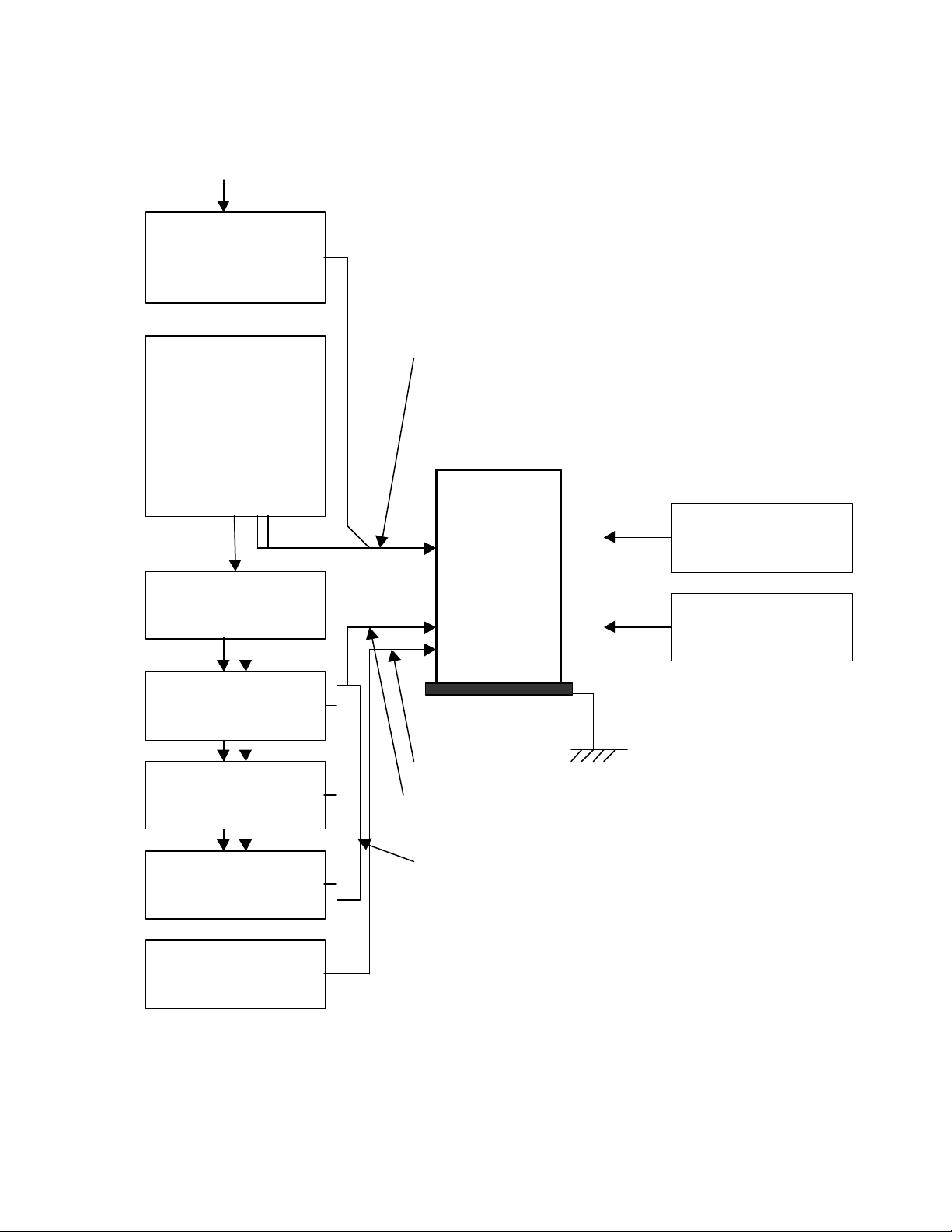
The interconnection of the High Gain Transmitter with the test support equipment is
shown in figure 8-1. The support hardware and software is shown in Table 8-1.
Using this support test equipment, the High Gain Transmitter will produce single or
multiple QPSK phase modulated Ka-Band output at user-selected bandwidths (as in the
SpectraPoint System) .
4.0 Description of the Test and Support Equipment
The support equipment required to operate the High Gain Transmitter in a stand-alone
mode is shown in Figure 8-1 and consists of:
• DC power source for the High Gain Transmitter
• 960 MHz reference signal
• source of the QPSK digitally-modulated signal (Rohde & Schwarz AMIQ Arbitrary
Waveform Generator and SMIQ Vector Signal Generator)
• Personal Computer with WinSim software to generate the QPSK I and Q Signals at
the AMIQ and NA1 software to provide RS-485 control to the High Gain Transmitter.
Page 2 of 8
Exhibit 8
FCC ID: NNSTX2000-HG-99
10/27/99
Page 3
-48 Vdc Power &
40 GHz
120 VAC 60 Hz
Power Input
AMIQ
Freq. Synthesizer
L-Band IF Signal
40 GHz
SMIQ
SMIQ
SMIQ
DC Power Supply
(-48 Volts)
Personal
Computer
(WinSim Software)
(NA1 Software)
(IEEE-488 Interface)
(Dual RS-485 Interface)
GPIB
Arbitrary Waveform
Generator
I Q
Vector Signal Generator
Vector Signal Generator
RS-485 Command Bus
High Gain
Transmitter
Reference Signal
(Single or Multicarrier QPSK)
Spectrum Analyzer
Power Meter
3-Way Signal Combiner
Vector Signal Generator
(960 MHz -7 dBm)
Figure 8-1 High Gain Transmitter Test and Support Equipment
Exhibit 8
FCC ID: NNSTX2000-HG-99
10/27/99
Page 3 of 8
Page 4

4.1 Generation of QPSK Test Signals
Test signals for the High Gain Transmitter, simulating I/F input from the SpectraPoint
Base Equipment, are generated in the AMIQ and transferred by operator command to
the SMIQ.
The WinSim software program is launched by double-clicking on the WinSim icon or by
selection from the Windows Program Start menu. The modulation parameters may be
manually entered through the PC keyboard or recalled from predefined parameters
stored on disk.
The NIU is capable of generating QPSK-modulated signals ranging from
approximately1.5 MHz bandwidth to 14.5 MHz bandwidth depending on a variety of
operating rates and error correction schemes required for reliable operation of an
SpectraPoint LMDS installation. The CPE Roof Unit test and support equipment has the
capability to simulate these complex signals and provide the DC power and enable
command to operate the unit for test and analysis.
4.1.1 Test Signals
The standard signal is stored in a data file on disk representing the widest bandwidth
signal that will be produced by the SpectraPoint Base Channel Group in operation.
Refer to Table 8-1 for the parameters.
Table 8.1 Parameters for Rohde & Schwarz AMIQ Modulation Setup
AMIQ Window
Data Source PRBS PRBS 9
Modulation Coding None
Modulation Type QPSK
Modulation Sequence Length 10,000
Modulation Filter Function Root Cosine
Modulation Window Function Rect
Modulation Symbol Rate 27.9 MSps
Modulation Oversampling 3
Main Sampling Rate 83.700MHz
Main Samples 30,000
Parameter Setting
Page 4 of 8
Exhibit 8
FCC ID: NNSTX2000-HG-99
10/27/99
Page 5

4.1.2 Single and Multiple Carrier Signals
One, two or three wideband QPSK channels may be applied to a High Gain Transmitter
in normal operation. The test support equipment setup shown in Figure 8-1 shows three
SMIQ vector signal generators driven be one AMIQ arbitrary waveform generator.
For single-channel operation, only one SMIQ vector signal generator is required. For
two-channel or three –channel operation, two or three SMIQ vector signal generators will
be required.
4.2 Command/Control of High Gain Transmitter
The operation of the High Gain Transmitter is software controlled using the NA1
software on the Personal Computer and transmitted to the High Gain Transmitter over
the RS-485 bus (part of the power/command multiconductor interface cable to the High
Gain Transmitter). The control program is activated by double-clicking on the NA1
program icon. Apply –48 Vdc power to the High Gain Transmitter prior to changing
operating parameters.
Caution:
Do not operate the High Gain Transmitter without a proper load on the RF output
port, either the High Gain antenna assembly or a dummy load.
If operating into the High Gain antenna, stay toward the rear (connector end) of
the transmitter to avoid potential hazardous RF radiation.
4.2.1 On the main NA1 window (refer to Figure 8-2), single-click on the Solid State Transmitter
“button”.
Page 5 of 8
Exhibit 8
FCC ID: NNSTX2000-HG-99
10/27/99
Page 6
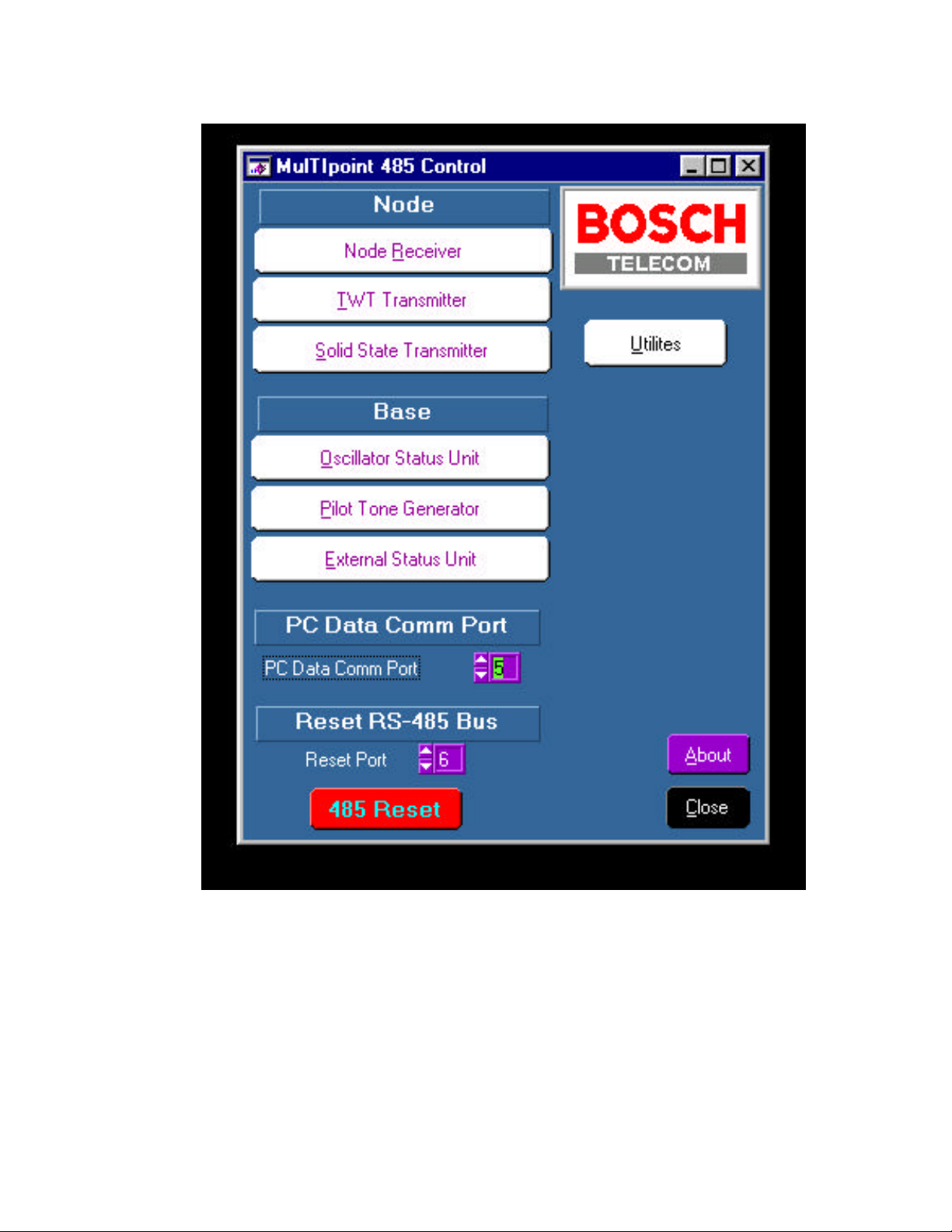
Figure 8-2 NA1 Main Window
Page 6 of 8
Exhibit 8
FCC ID: NNSTX2000-HG-99
10/27/99
Page 7

4.2.2 On the Parameters Selection Window (refer to Figure 8-3), update the
parameters per Table 8-1:
Table 8-1 SpectraPoint High Gain Transmitter Operating Mode Setup
Transmitter Parameter Range
Transmitter Address 129 to 191 191
Set Light On/Off Don’t Care
ALC Mode On/Off Off
RF Bit Threshold 12.0 to 30.0 [dBm]
Power Control On/Off On, press “Send”
Read from EPROM 0 to 255
Store to EPROM 0 to 255
LO Frequency 25880 – 27050 MHz 26550 MHz, press “Send”
IF Attenuation 0 – 40 [dB] 0 dB, press “Send”
RF Target 12.0 to 30.0 [dBm]
IF Bit Threshold -17.0 to 3.0 [dBm]
Do not press “Send”
Do not press “Send”
Do not press “Send”
Do not press “Send”
Do not press “Send”
Setting
Page 7 of 8
Exhibit 8
FCC ID: NNSTX2000-HG-99
10/27/99
Page 8
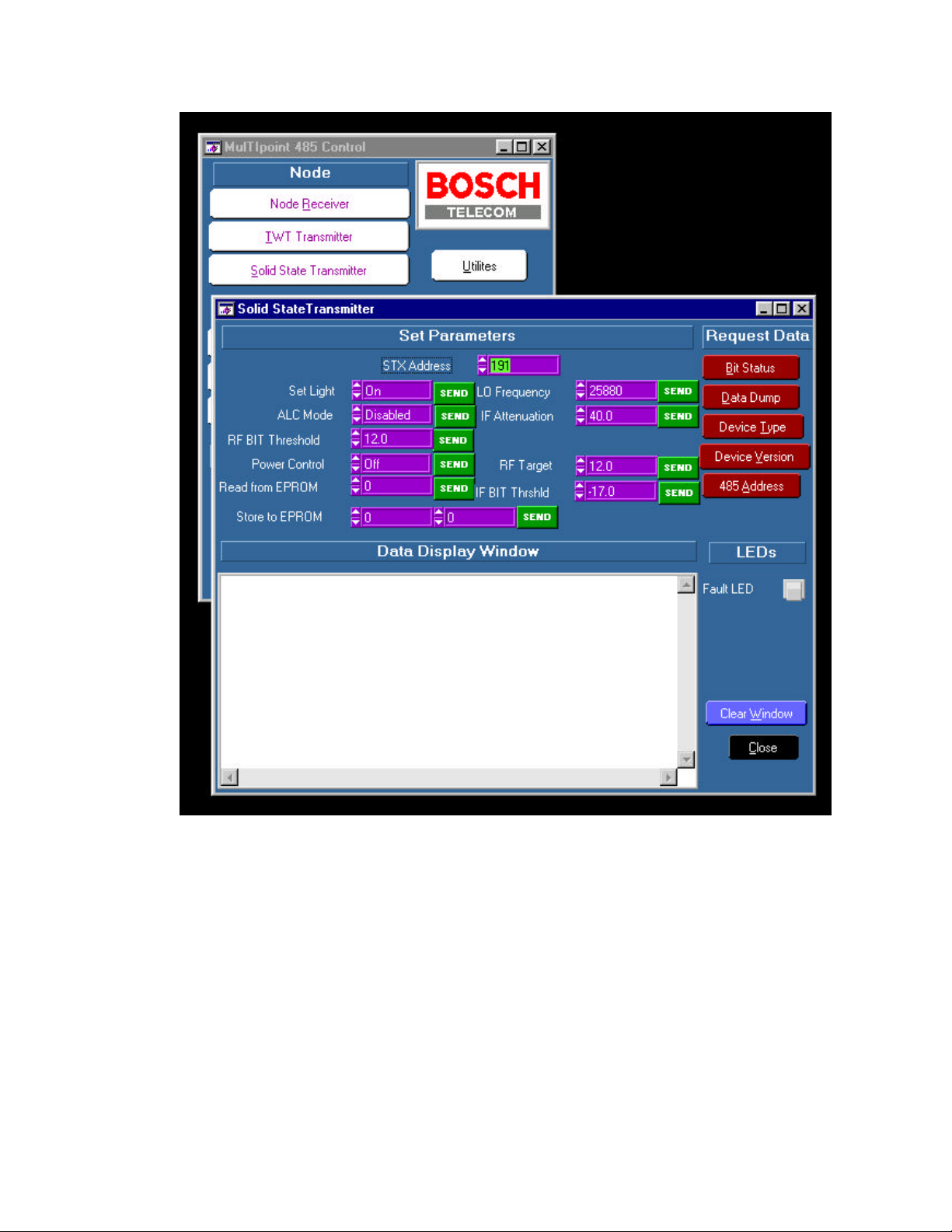
Figure 8-3 Solid State Transmitter Parameter Selection Window
4.2.3 Press the Data Dump “button” to display status of the High Gain Transmitter and verify
that commands have been properly processed.
4.2.4 Increase the IF power input for the desired RF output power level.
Exhibit 8
FCC ID: NNSTX2000-HG-99
10/27/99
Page 8 of 8
 Loading...