

Spectra-Physics Quanta-Ray GCR-16, Quanta-Ray GCR-14, Quanta-Ray GCR-12, Quanta-Ray GCR-18 Instruction Manual
—©
Quanta-Ray
4.’—
Pulsed
,
.
.
iia
)IIIIIlIIIIIflhIIIIiliii
IIlIllhIlllhIllllhIIIfII
IIIllhlIIOhlllllflIllhI
11111
Nd:YAG
Instruction
Lasers
Manual
GCR-12
GCR-L4
GCR-18
Spectra-Physics
SpectraPhysics
Lasers

—©
Quanta-Ray
Pulsed
Nd:YAG
Instruction
Lasers
Manual
GCR-12
GCR-14
GCR-16
GCR-18
Spectra-Physics
Spectra-Physics
Bella
Terra
1330
Post
Office
Mountain
Part
View,CA94039-7013
International
Siemensstrasse
D-61
Number
0000-225A,
Headquarters
00
Lasers
Avenue
7013
Box
Darmstadt
Germany
Rev.
1992
April
20
A

This
manual
operation
Nd:YAG
operation,
contains
and
maintenance
Laser
System. You
preventive
andatroubleshooting
elements—the
tion
to instructions
installation
laser
and
operation
information
you
of your
will
find
maintenance,abrief
and
repair
head
power
for these
of
guide.
supply,
components,
the
HG-2
will
need
QuantaRay®
instructions
descriptionofits
The
system
and
remote
the
manual
harmonic
Preface
for
day-to-day
OCR
for installation,
generator.
Series
circuitiy,
comprises
control. In
describes
three
addi
the
While
this
intended
Please
wait
assigned
those
up
The
you
as
to
failures
The
damage
over,
put
Laser
qualified
your
laser
Service
guide your
guidetorepairs
a
repair
to
OCR
eyes
focused
energy
Safety
hazards.
carefully
If
you
encounter
please let
problems
Physics
instruments.
manual
as
a
for
this
containsabrief
guide
to
the
Spectra-Physics
taskaspartofyour
and
authorized
system.
and
Repair
field
service
you
the
unit
while
Spectra-Physics
Series
can
To
follow
us
to
lasers
and
skin,
back
reflections
destroy
section
minimize
these
any
know.
our
attention.
contains
the
instructions.
difficulty
The
installation
the
initial
installation and
service
purchase agreement.
Spectra-Physicstoinstall
by
sectionisintended
engineer
may
choose
itisunder
customer
emit
laser
ignite
fires,
of
expensive
to
to
warranty;
service
radiation
and vaporize
evenasmall
internal
information
risk
of
injury,
the
with
last
page
isaformtoaidinbringing
Thank
you
procedure,
set-upofyour
engineer
both
as
the
sourceofproblems,
do
yourself.
instead,
for
warranty repair.
that
can
substances.
percentage
optical
and
guidance
death,
content
for
or
or
your
expensive
styleofthis
purchase of
itisnot
who
has
been
Allow
and
an
aidtohelp
not
Do
report
attempt
all
permanently
More
of
its
components.
about
repairs,
manual,
Spectra
laser.
only
set
and
system
out
The
these
such
III
Table
of
Contents
Chapter
Emission
Population
Nd:YAG
Q-switching
Resonant
Longitudinal
Producing
Resonator
Pulse
Specifications
Chapter
Precautions
Focused
Maintenance
in
Compliance
Radiological
Sources
Introduction
1
Absorption
and
Inversion
an
as
Optical
Modes
Other
Structural
Triggering
Laser
2
for
Back
Required
Health
of
Excitation
Cavity
and
Wavelengths
Considerations
Sequence
Safety
Safe
the
Reflection
to
with
Center
(CDRH)
Laser
Safety
Light
of
Medium
Linewidth
and
Timing
Operation
Safety
this
keep
Devices
for
Regulations
Standards
of
Class
Laser
Product...
and
IV-High
Power
Lasers
1—1
1—1
1-3
1-4
1-6
1-7
1-8
1-10
1—11
1-12
1-14
2-1
2-1
2-3
2-3
2-4
Chapter
Unpacking
Installing
Connecting
Filling
Controls
Controls
OUTPUT
lNPUTConnectors
REMOTE
COMPUTER
POWER
PURGE
Power
Installation
3
your
Laser
the
Cooling
the
Connections—Remote
and
and
Connections—Power
Connectors
Connector
Controls
Controls
Supply
Laser
the
Electrical
Connector
Rear
and
System
Panel
Operation
Service
Supply
Control
Module
3—1
3-1
3-1
3-1
3-2
3-3
3-5
3-5
3-5
3-6
3-6
3-6
3-7
3-7
V

Table
Contents
of
(cont.)
Chapter
Controls
Q-switch
Emission
Convenience
Starting
Chapter
Functional
Computer
IEEE
RS-232-C
Message
CIM-1
Examples
Example
Installation
3
Connections—Laser
and
Driver
Indicator
Laser
the
Computer
4
Overview
Control
Power-On
Computer
488
Operation
Remote
Serial
SW2
Operation
Data
SW1
SW3
Command
Response
Commands
CONFIGURE
SAMPLE
SELECTc
WRITEp,n
SELECT
SELECT
SELECT
SELECT
SETd,n
External
Variable
Q-switch
Sample
Default
Safety
Interface
Reset
Status
Poll
Switch
DIP
Serial
Transfer
DIP
Switch
DIP
Switch
Formats
Format
a
1,
1,
1,
1,
lamp
rep
Advance
Analog-to-Digital
Commands
(Marx
Receptacle
and
State
(Watchdog)
Byte
Setting
Interface
and
Setting
Setting
Format
OUTPUT,
p,
WRITE
WRITE
WRITE
WRITE
fire
rate
Operation
and
Bank)
Box
Interface
Diagnostic
System
and
Handshaking
NONCLOCKED
4,
n
n
5,
n
6,
7,
n
Sync
Conversion
Using
GW
Head
Module
Functions
Interlock
BASIC
(cont..)
Initialization
a
Personal
on
Computer
3-1
3-8
3-8
3-8
3-8
3-9
4-1
4-1
4-3
4-3
4-4
4-4
4-4
4-4
4-5
4-6
4-6
4-6
4-7
4-8
4-8
4-8
4-8
4-9
4-10
4-10
4-11
4-11
4-13
4-13
4-13
4-13
4-15
4-15
4-15
4-15
4-16
4-17
4-18
VI
Chapter
Installing
5
HG-2
and
Harmonic
Operating
Generator
the
TableofContents
(cont.)
5-1
HG-2
Installing
Operation
TypeIandIICrystals
HG-2
Controls
Operating
Second
Third
Chapter6
Maintaining
Maintaining
Maintaining
Replacing
Procedure
Replacing
Procedure
Replacing
Procedure
Controls
the
Temperature
Voltage
Harmonic
and
Fourth
Maintenance
the
Cooling
Air
the
the
HG-2
the
Deionizing
the
Air
Flash
the
HG-2
Controller
Harmonic
Purge
Filters
Lamps
(TypesIand
Generation
System
System
Water
Filter
II)
5-3
5-3
5-4
5-5
5-6
5-6
5-6
5-7
6—1
6-1
6-i
6-i
6-2
6-2
6-3
6-3
6-4
6-4
Chapter7ServiceandRepair
System
System
Description
Computer/Internal
Enabling
Analog
Q-switch
Q-switch
Mode
Q-switch
Single-Shot
Inhibit
OFF
Interlock
Pulse
Flash
Signals
Signals
Delay
Advanced
Switch
Switch
[STOP]/ON
Forming
Lamp
Start-up
(Ui
Drivers
Operation
Logic
Simmer
Tests
Network
Switch
Sync
1)
[ENABLE]
Supply
Generator
buttons
7-1
7-i
7-1
7-i
7-1
7-2
7-2
7-2
7-3
7-3
7-3
7-3
7-4
7-4
7-5
7-5
VII

Table
Contents
of
(cont.)
ChapterlOCustomerService
Warranty
Instrument
the
Centers
Electrons
probability
the
radial
A
Compared
Energy
The
polarization
Stable
Frequency
Etaton
Simplified
Radiation
Warning
Main
Cooling
Remote
Power
Q-switch
Head
Location
Diagram
Standard
Command
4-4:
CIM-1
4-5:
HG-2
5-1:
Temperature
5-2:
Short
6-1:
when
occupy
of
shape
Typical
of
and
Four-level
angular
Level
Q-switch
and
Loss
Block
Control
Labels
autotransformer
System
Control
Supply
Driver
Emission
of
of
RS-232-C
Proprietary
Component
together
servicing
to
rotator,
Unstable
Distribution
CIM-1
the
Word
List
Return
Service
Figures
of
Figure
Figure
Figure
Figure
Figure
Figure
Figure
Figure
Figure
Figure
Figure
Figure
Figure
Figure
Figure
Figure
Figure
Figure
Figure
Figure
Figure
Figure
Figure
Figure
of
1-1:
1-2:
1-3:
1-4:
1-5:
1-6:
1-7:
1-8:
2-1:
2-2:
3-1:
3-2:
3-3:
3-4:
3-5:
3-6:
4-1:
4-2:
4-3:
Repair
for
distinct
finding
the
orbital
dependence
Transition
of
that
Scheme
comprises
and
Minimum
Diagram
Drawing
Component
Panel
Control
(Marx
Indicator
PC
serial
Abbreviations
PC
Identification
Control
posts
flash
the
defined
at
determined
the
of
an
orbitats
electron
being
Scheme
Nd:YAG
for
Resonator
of
Tuned
is
(b)
Nd:YAG
the
polarizer,
a
Pockets
a
Configurations
Longitudinal
Laser
to
GCR
of
tapped
for
Series
Identification
Panel
Bank)
Box
Boards
poll
status
byte
Interconnections
Board
Panel
prevent
to
B
and
A
lamps.
given
a
probability.
(a)
Laser
quarter-wave
a
cell.
Modes
Gain
Electronics
several
shock
the
by
position,
the
by
Source
for
Maximum
operating
Single
a
Line
voltages
8-1
8-1
8-2
8-2
1-2
1-4
1-5
1-6
1-7
1-9
1-9
1-12
2-5
2-6
3-2
3-3
3-4
3-6
3-8
3-9
4-2
4-5
4-7
4-10
4-14
5-1
5-6
6-5
VIII
List
of
Tables
Table
of
Contents
(cont.)
Table
Table
Table
Table
Table
Table
Table
Table
Table
Table
4—1:
SW2
DIP
4-2:
SW1
Baud
4—3:
SW1
Mode
4—4:
Sample
4—5:
SELECT
4-6:
SELECT2,WRITE
5—1:
Summary
Summary
5—2:
System
7—1:
7—2:
Replacement
Switch
Rate
Select
Command
a
1,
WRITE
of
Translation
of
HG-2
Start-up
Parts
Settings
Settings
Settings
Functions
Command
Command
Positions
for
Arm
Selecting
Functions
Functions
Positions
Device
Address
4-6
4-8
4-8
4-11
4-12
4-13
5-2
5-2
Tests 7-7
7-13
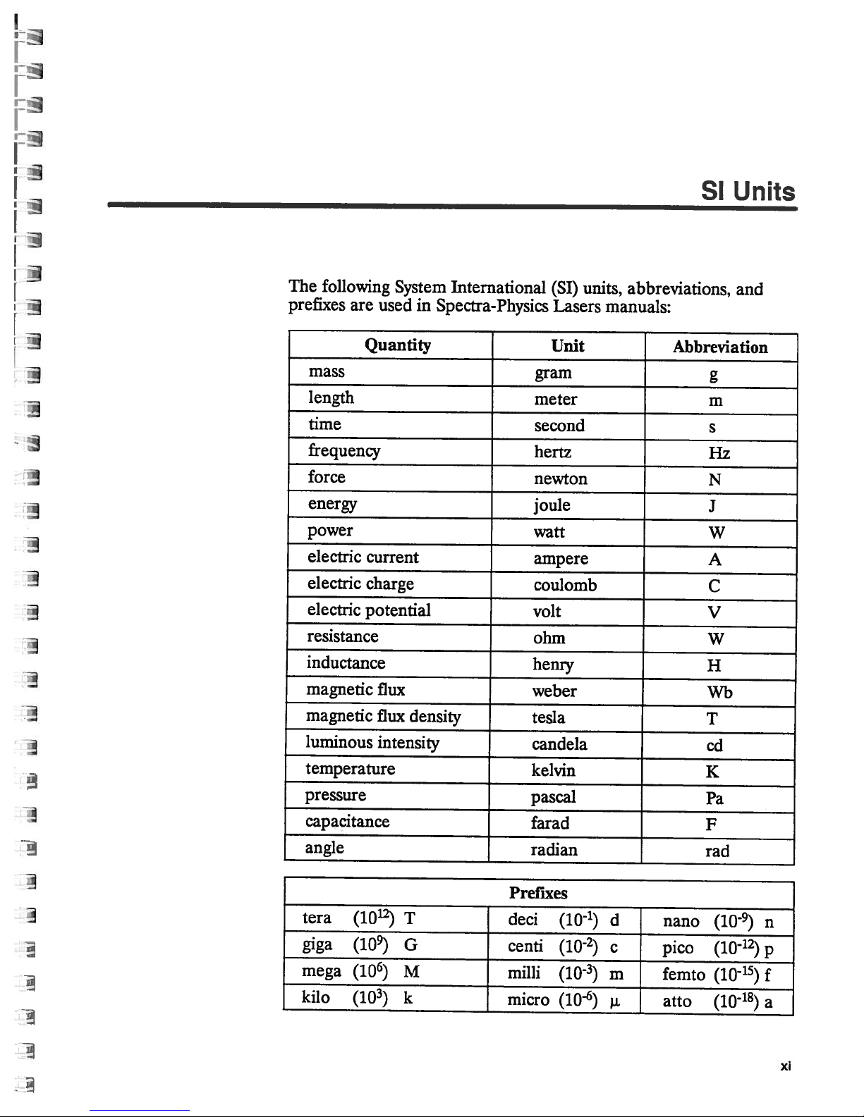
The
following
prefixes
are
System
used
International
in
Spectra-Physics
units,
(SI)
Lasers
abbreviations,
manuals:
SI
Units
and
Quantity
mass
length
time
frequency
force
energy
power
electric
electric
electric
current
charge
potential
resistance
inductance
magnetic
magnetic
luminous
temperature
pressure
capacitance
angle
flux
flux
density
intensity
Unit
gram
meter
second
hertz
newton
joule
watt
ampere
coulomb
volt
ohm
henry
weber
tesla
candela
kelvin
pascal
farad
radian
Abbreviation
g
m
s
Hz
N
J
W
A
C
V
W
H
Wb
T
cd
K
Pa
F
rad
tera
giga
mega
kilo
(1012)
(1O)
(106)
(10)
T
G
M
k
Prefixes
deci
centi
milli
micro
(10-1)
(102)
(10)
(10-6)
d
c
m
nano
pico
femto
atto
(10)
(1012)
(10-15)
(10-18)
n
p
f
a
xi
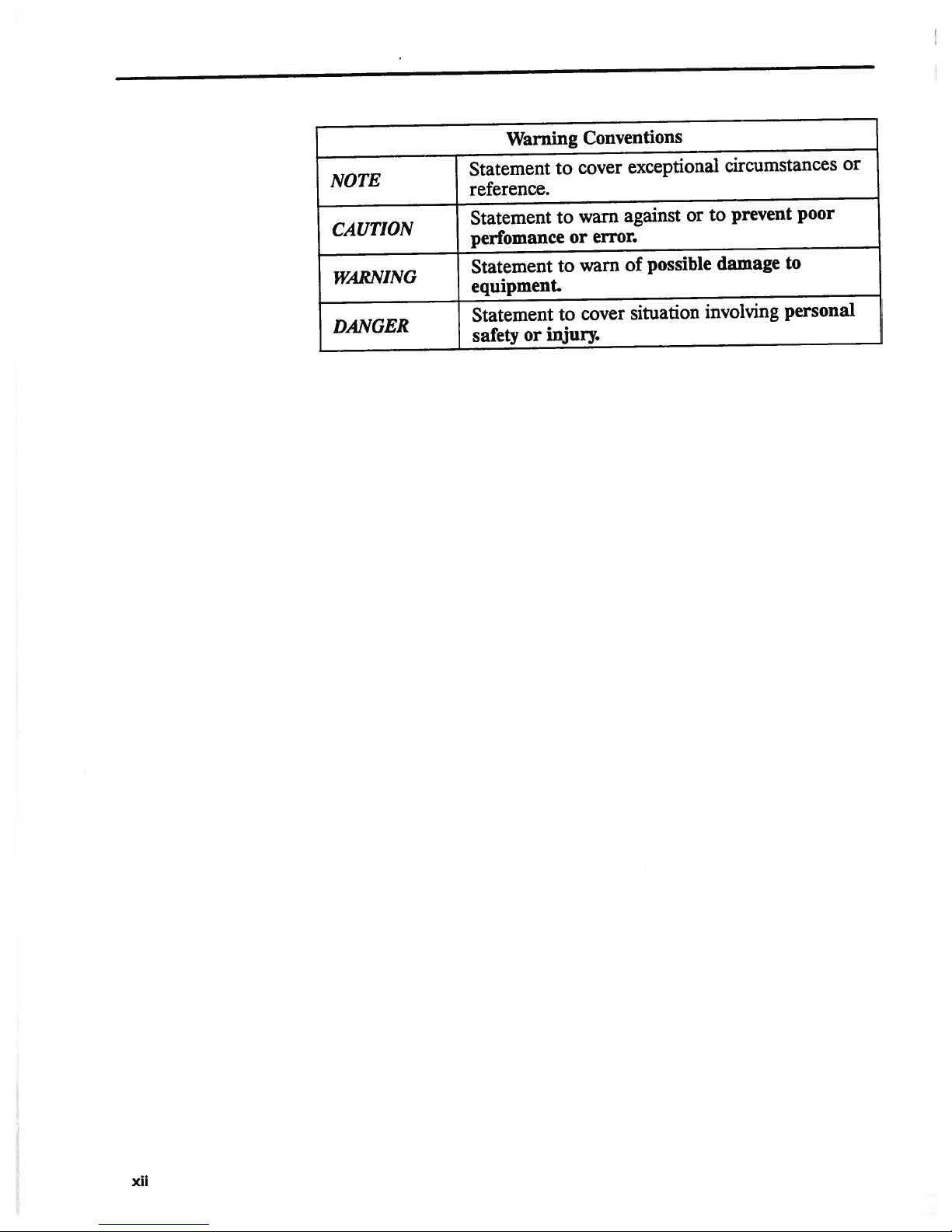
NOTE
CAUTION
WARNING
DANGER
Warning
Statement
reference.
Statement
perfomance
Statement
equipment.
Statement
injury.
safety
or
Conventions
cover
to
warn
to
error.
or
warn
to
cover
to
exceptional
against
of
or
possible
situation
circumstances
prevent
to
damage
involving
or
poor
to
personal
XII

Chapter
1
Introduction
Emission
and
Absorption
Laser
lated
emit
relationship
amplifier
identical
sources.
matic,
Radiant
molecular
structure
nucleus
a
distinct
at
a
teristic
that
all
“p”
lobed
mined
atom—its energy
throughout
levels:
state,
in
its
forces.
Light*
of
is
an
acronym
Emission
light
in
all
with
of
light,
in
phase,
Its
output
and coherent.
emission
structure
describes
with
oneormore
orbital
given
position
shape
thatisdefined
probability,
orbitals
configuration
by
the
orbital
the
the
level
and
higher
ground
state,itwill
derived
of
Radiation.”
directions,
one
another.
and
because
direction,
beam
and
that
is
absorption
of
materials.
an
electrically
represents
relative
all
e.g.,
surround
“s”
the
(Figure
thatitoccupies,
level—depends
available
with
energy
the
orbitals.
lowest
levels
from
Thermal
the
individual
But
its
and
singularly
electrons
the
to
the
by
the radial
orbitals
x,
andzaxes
y,
1—1).
possible
are
stay
there
“Light
Amplification
radiators,
photons
because
output
comprises
amplitude,
directional,
take
place
The
contemporary
neutral
system
bound
probability
nucleus.
and
are
spherically
The
energy
and the
on
the
distribution
Each
atom
energy
called
excited
untilitis
the
laser
itisunique
within
to
it.
Each electron
of
Each
orbital
angular
of
the
of
over-all
has
is
excited
by
Stimu
suchasthe
having
is
an
no
oscillating
photons
among
intense,
the
atomic
model
monochro
of
composed
finding
the
has
dependence of
symmetrical,
nucleus
an
inadouble-
electronisdeter
energy
of
its
electrons
array
an
called
states.
the
If
by
of
an
external
sun,
definite
that
are
light
or
atomic
of
a
occupies
electron
a
charac
and
of
an
energy
ground
atom
is
*
“Light”
infrared
will
be
usedtodescribe
to ultraviolet.
the
portion
of
the electromagnetic
spectrum
from
far
1—1

Quanta-Ray
GCR
Series
x.
x
Figure
the
of
dence
1—1:
probability
orbital
the
of
Movement
when
be
the
caused
transitions
photon
content
energy
levels,
where
of
is
of
i.e.,
h
Likewise,
equal
state,
energy
to
the
hv
probabiit
the
from
atom
by
in
light.
E
1
the
Planck’s
is
when
E2—E1.
atom
and
Electrons
finding
of
being
determined
one
either
collision
directions
both
Consider
higher
a
to
incident
constant,
atom
an
Because
may
frequency
occupy
energy
absorbs
with
a
one
photon
hv=E
2—E1
excited
its
decay
distinct
electron
an
the
by
another—a
to
level
emits
or
electron
free
a
occur
as
transition
energy
with
matches
v
and
E
2
to
tendency
spontaneously,
orbitals
at
radial
energy.
result
a
from
the
the
is
decays
is
given
a
and
Upward
an
or
of
lower
a
It
E2.
energy
[1]
frequency
toward
emitting
[2]
defined
are
that
shape
position,
angular
the
depen
transition—happens
transitions
with
occur
the
energy
and
energy
if
between
photon.
energy
excited
interaction
level
only
will
difference
of
it
E1,
to
lower
the
atom,
whose
loses
photon
a
by
can
a
the
with
1-2
Spontaneous
energy
lost
collision
ulated
shedding
the
with
decay
to
energy
incident
spontaneous
phase
relationship
decay
taking
another
to
one
emission
can
another
E
1
in
the
in
phase,
with
also
form,
atom.
interacting
by
form
frequency,
produces
one
occur
e.g.,
atom
An
pair
of
a
photons
another.
without
transfer
excited
with
of
and
emission
of
to
photon
a
photons
direction.
have
that
of
kinetic
can
E
2
of
that
By
no
photon,
a
energy
be
also
frequency
identical
are
contrast,
directional
the
by
stim
v,
to
or

Introduction
Population
Inversion
laser
A
taneous
conditions
describe
The
tween the
be
both
probability.
to
Moreover,
dent
tion.”
same
depends
andN2
When
of
all
frequencies
any
is
and
these
absorption
shown
number
the
the population
wave
It
can
regardless
only
,
and
material
a
its
atoms
atoms
frequency
designed
stimulated
favorable
conditions.
coefficient
rates
of
that
the
Similarly,
the
transition
and
a
also
of
on
flux
the
over
in
ground
the
exceeds
positive.
is
take
to
to
emission
rate
of
atoms
of the
characteristic
be
shown
direction.
the
difference
of
isatthermal
the array
that
advantage
emission
light
at
of excitation
in
the
rate
upper
probability
that
incident
the
of
state.
of
of
phenomena,
amplification.
given
a
and
the
of
level
of
Therefore,
between
equilibrium,
available
Since
emission,
frequency
absorption
from
lower
stimulated
(N2)
depends
transition
the
the
transition
wave.
energy
the
the
absorption,
using
The
at that
E
1
to
(N1)
level
emission
the
and
on
cross
absorption
the
the
populations
a
Boltzmann
levels
rate
of
absorption
and
them
following
is
E
2
called
difference
the
frequency.
is
proportional
and
the
is
transition
the
flux
its
section
exists
absorption
coefficient
both
spon
create
to
paragraphs
be
can
It
transition
proportional
probability.
is
of
inci
sec
the
nearly
all
at
of the
“cross
coefficient
involved,
distribution
with
to
N
1
If
enough
shifted
and
frequency
levels,
equality;
sition
However,
relationship
excitation
A
(a).
toE4.If
E1,
E3.
lifetime,
from
ton of
to
ing
kept
inversion
coefficient
through
greater
untilN2
stimulated
it
is
is
matched
model
A
photon
theE4
and
if
IfE3
the
above.
frequency.
the
ground
the
rate
large
the
the
that
four-level
is
between
light
of
frequency
=
N1.
emission
v
is
zero.
If
impossible
is,N2
if
three
satisfies
can
of
E
4
is
metastable,
population
TheE3
state,
of
and
atv2becomes
material,
population
can
by
or
certain
create
laser
frequency
E
3
to
unstable,
atom
Finally,
E1,
absorption
that
of
E
3
v
Under
the transition
to
one
more
a
transition
E
2
and
which
these
are
equal,
drive
never
in
the opposite
energy
requirements
population
transition
v1
excites—or
the
atom
i.e.,
atoms
will
grow
will
eventually
ifE2
keeping
of
v2
.
remains
E2.
Under
negative.
is
now
inversion,
is
supplied,
conditions
and
scheme
the populations
exceed
levels
inversion,
scheme
probability
will
that
rapidly
is
unstable,
the
population
In
this
low,
these
Lightisamplified
called
the
the
the
because
N
1
direction.
are
described
“pumps”—an
is
decay
occupy
as
decay
its
way
thus
establishing
conditions,
an “active
greater
populations
the
rates of
absorption
is
limited
involved
every
employed,
below,
in
which
is
depicted
greater
almost
it
excited
atoms
the
the
immediately
have
atoms
toE2,emitting
will
of
E
2
population
as
medium.”
gain.
absorption
coefficient
two
to
beyond
upward
andiftheir
additional
N2>
in
Figure
atom
than
thatofE
a
relatively
cascade
rapidly
small
of
a
population
the
absorption
it
passes
can
N1.
and
be
energy
tran
from
to
long
a
pho
return
reduc
E3is
The
at
1—2
E
1
4
to
1-3
Quanta-Ray
GCR
Series
cm
1
E
3
E
2
I9/2
11502
2111
Nd
ctrf
1
3
+
Nd:YAG
as
Excitation
an
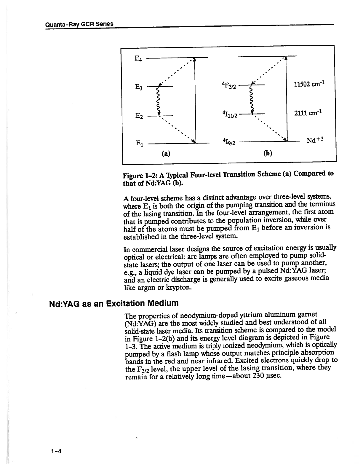
Figure
that
A
where
of
that
half
1—2:
Nd:YAG
of
four-level
E
1
lasing
the
pumped
is
the
of
established
commercial
In
optical
state
e.g.,
and
like
or
lasers;
liquid
a
electric
an
argon
Medium
properties
The
(Nd:YAG)
solid-state
Figure
in
The
1-3.
pumped
F
372
in
for
bands
the
remain
(a)
Typical
A
scheme
is
both
transition.
atoms
the
in
laser
electrical:
the
dye
or
krypton.
are
laser
1—2(b)
active
flash
by
a
the
red
level,
the
relatively
a
Four-level
(b).
distinct
a
has
In
be
of
the
to
pumped
origin
the
contributes
must
three-level
designs
lamps
arc
one
output
laser
discharge
of
the
media.
and
medium
and
of
be
can
generally
is
neodymium-doped
widely
most
transition
Its
energy
its
triply
is
whose
lamp
infrared.
near
upper
level
long
Transition
advantage
pumping
the
four-level
population
the
from
system.
source
the
often
are
can
laser
pumped
used
yttrium
studied
scheme
diagram
IeveJ
ionized
output
Excited
the
of
lasing
time—about
(b)
Scheme
over
transition
arrangement,
inversion,
E1before
excitation
of
employed
used
be
pulsed
a
by
excite
to
aluminum
best
and
compared
is
is
neodymium,
matches
electrons
transition,
230
lisec.
Compared
(a)
three-level
and
the
while
inversion
an
energy
to
pump
pump
to
Nd:YAG
gaseous
understood
depicted
which
principle
quickly
where
systems,
terminus
the
atom
first
over
usually
is
solid-
another,
laser;
media
garnet
all
of
model
the
to
Figure
in
is
optically
absorption
drop
they
to
is
to
1-4
Introduction
—
20
FZ
Pump
Bands
18
16
-
_—
11502
cmR2
11414
R
1
Transition
cm
1
6000
“4000
cm
2473
I15/2,
113/2,:
111/2
-‘:_______
%/2
---_____
,:-
—------.
Laser
—2526
—---—--
.-.-.-.-
14
-
E
12-
C.)
Laser
10
8-
6-
4.
2-
-
115/2
13/2
Transition
--- -
--
-.
-
__4
-.
- -
-
-
- -
-
- -
0-
Ground
Level
311
134
\
0
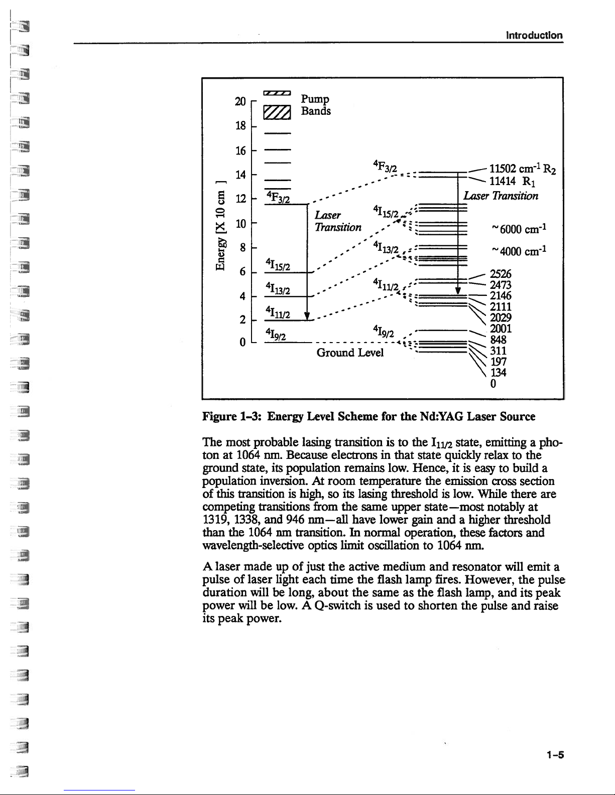
Figure
most
The
ton
at
ground
population
of
this
competing
1319,
than
1338,
the
Energy
1—3:
probable
1064
nm.
Because
its
state,
population
inversion.Atroom
transitionishigh,
transitions
and
946
1064
nm
transition.
wavelength-selective
A laser
pulse
duration
power
its
peak
made
of laser
willbelong,
will
be
power.
upofjust
light each
low.
Level
lasing
Scheme
transition
electronsinthat
remains
its
so
from
the
nm—all
optics
limit
the
time
about
A
Q-switch
for
the
is
to the
low.
Hence, itiseasytobuild
temperature
lasing
have lower
In
same
normal
threshold
upper
gain
operation,
oscillationto1064
active
the
medium and
the
flash
sameasthe
is
used
lamp
to
Nd:YAG
‘1i12
state
the
Laser
state,
quickly
emission
is
low.
Source
emitting
relax
cross
While
state—most notably
and
higher
a
these
factors
nm.
resonator
fires.
However,
flash
shorten
lamp,
the
and
pulse
pho
a
to
the
a
section
there
are
at
threshold
and
will
emit
the
pulse
its
peak
and
raise
a
1—5
Quanta-Ray
0-switching
GCR
Series
Because
population
much
while
quickly
as
the
released,
upper
the
excited
of
capacitor
a
population
level
the
stores
inversion
laser
transition
the
of
neodymium
electrical
builds,
emit
will
ions
energy.
short
a
can
and
has
build
If
if
pulse
the
lifetime,
long
a
in
up
oscillation
stored
high
of
the
YAG
prevented
be
energy
intensity
a
large
rod,
can
light.
be
electro-optic
An
cillation.
quarter-wave
a
the
istics,
closed
As
Pockels
which
(high
ctor
Quarter-Wave
Plate
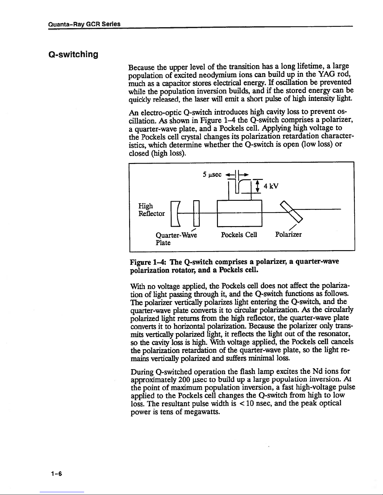
Figure
1—4:
polarization
With
tion
The
voltage
no
light
of
polarizer
quarter-wave
polarized
converts
mits
the
so
the
mains
light
it
vertically
cavity
polarization
vertically
0-switch
shown
plate,
cell
crystal
determine
loss).
Q-switch
The
rotator,
applied,
passing
vertically
plate
returns
horizontal
to
polarized
is
loss
retardation
polarized
Figure
in
and
changes
whether
sec
5
and
the
through
polarizes
converts
from
polarization.
light,
With
high.
introduces
1—4
Pockels
a
its
the
Pockels
comprises
Pockels
a
Pockels
it,
and
light
circular
to
it
high
the
it
reflects
voltage
the
of
suffers
and
cavity
high
Q-switch
the
Applying
cell.
polarization
0-switch
—
—i’
Cell
polarizer,
a
cell.
does
cell
Q-switch
the
entering
polarization.
reflector,
Because
light
the
applied,
quarter-wave
minimal
loss
comprises
high
retardation
open
is
Polarizer
a
quarter-wave
not
affect
functions
the
Q-switch,
quarter-wave
the
polarizer
the
outofthe
Pockels
the
plate,
loss.
prevent
to
voltage
(low
the
As
so
polarizer,
a
character
loss)
polariza
follows.
as
and
circularly
the
only
resonator,
cancels
cell
light
the
Os
to
or
the
plate
trans
re
1—6
During
0-switched
approximately
the
point
applied
loss.
power
of
the
to
resultant
The
is
tensofmegawatts.
operation
jisec
200
maximum
Pockels
pulse
the
build
to
population
changes
cell
width
is
flash
a
large
up
inversion,
the
nsec,
<10
lamp
excites
population
a
0-switch
and
the
fast
high-voltage
from
peak
the
ions
Nd
inversion.
pulse
hightolow
optical
for
At

Introduction
Resonant
Optical
This
short
the
pulsed
conversion
doubling,
conversion.
fast
phenomena
An
alternative
GCR.
fires,
result
Voltage
and
is
between
pulse
train
pulse
mode
ments
where
critical
Cavity
A
resonant
the
cavity
active
and
to
the
Stimulated
direction
eight,
equilibrium
pulse
Nd:YAG
through
frequency
A short
the
Q-switch
train
a
individual
similar
is
allows
total
factor.
cavity,
medium.
are
reflected,
emission
from
the
between
of
high
laser.
several
mixing,
pulse
like
“long
is
applied
of
pulses
pulsesof2
to
safer
pulse
which
produces
interaction.
each
numbers
peak
Its
nonlinear
provides
pulse”
to
held
is
chemical
mode
the
rapid
about
that
of
alignment
energy,
is
defined
Photons
returning
continue
excitation
power
high
dye
Pockels
open
200
to
a
single
emitted
two
The
to
and
peak
laser
excellent
reactions
of
for
i.zsec
4
isec.
and
its
not
by
interact
to
photons
two
increase
emission
is
the
key
power
processes,
pumping,
operation
cell
as
entire
the
long,
The
Q-switched
set-up,
distribution
mirrors,
two
parallel
with
of
become
geometrically
is
to
the usefulness
permits
e.g.,
or
Raman
temporal
or
high-speed
is
built
soon
lamp
with
a
energy
total
pulse.
and
is
useful
in
provides
the
to
other
equal
energy,
four,
reached.
wavelength
frequency
frequency
resolution
in
to
the
flash
as
firing.
separation
of
This
in
time,
feedback
optical
excited
phase
four
become
until
of
motion.
the
lamp
The
the
long
experi
the
is
axis
of
ions.
an
of
and
Both
mirrors
interest
while
are
transmitting
coupler—transmits
the
escaping
There
(Figure
ray
of
light
the
stable
cavity
laser.
mirrors,
By
reflected
Figure
are
1—5:
radiation
two
1—5).
traveling
resonator
contrast,
away
Stable
major
The
so
from
coated
fraction
a
becomes
types
difference
close
the
ray
it
is
always
a
ray
travellinginan
the
axis
and
Unstable
reflect
to
all
others.
of
the
the
of
optical
between
to,
and
parallel
is
reflected
contained along
one
by
Stabl
Unstable
Resonator
wavelength,
the
One
energy
output
resonators:
them
toward
unstable
of
the
or
of the
beam
stored
mirrors—the
in
of
the
stable
in
lies
with
the
the
the
what
optical
optical
primary
resonator
cavity
mirrors.
Configurations
wavelengths,
output
the
cavity,
laser.
and
unstable
happens
axis.
axis
by
axis
of
can
be
and
to
In
of
a
its
the
1—7
Quanta—Ray
GCR
Series
Stable
the
put.
Thus,
resonators
optical
axis
Conversely,
can
they
cross-sectional
In
the
coupler
the
and
resonator
output
The
forms.
substrate
escapes
“diffraction
partially
(an
a
The
is
replaced
RVR
employs
substrate.
reflector
tivity
near-gaussian
sian
coupled
If
Nd:YAG
at
to
formance,
rod,
energy
the
focus
one
reflected
be
Uniform
Nd:YAG
length
focal
which
the
of
be
rod
carefully
rod
cooling
lasers.
depends
the
must
also
controlled
can
of
the
unstable
efficiently
is
area
in
case,
first
placed
coupled
reflective
is
third
by
optic).
spatial
resonator”
the
be
elliptical
an
output
of
must
of
through
is
also
When
reflector
high
remain
causes
extract
only
resonator,
resonators
extract
large,
an
unstable
small
a
the
on
diffracting
by
resonator”
variation
a
a
partial
reflector
This
profile
at
(OCR)
beam
uniformly
chamber
the
rod,
essential
heated,
average
the
on
must
stable
radially
a
the
for
energy
which
can
energy
of
that
like
resonator
reflector
high
optical
axis
around
(DCR)
on
that
the
coating
reflector
is
capable
the laser
name.
its
is
to
illuminated.
causes
whichisplaced
optimal
to
Nd:YAG
the
power
matched
be
during
operation.
variable
beam
best
from
have
from
the
large
active
limits
typical
can
is
the
of
this
name.
its
uniformly
where
first,
radially
with
of
output,
be
uniformly
Placing
all
performance
rod
absorbed.
to
polarization
quality.
small
volume
a
energyofthe
beam
media
Nd:YAG
one
take
mounted
resonator.
which
dot,
second
A
covers
the
variable
producing
gives
and
distributed,
the
the
light
the
at
other
of
becomes
For
focal
the
The
thermal
rotation
diameters.
whose
rods.
laser
three
of
a
clear
on
Energy
gives
form
the
small
reflec
gaussian
the
“gaus
lamp
flash
produces
it
focus.
pulsed
lens
a
optimal
length
gradient
that
near
out
the
whole
high
or
the
whose
per
of
the
must
Longitudinal
1—8
Modes
Linewidth
and
oscillates
laser
The
transition
frequency.
Iinewidth—and
perature,
determined
is
the
width
(full
The
broadened
ity,
and
will
cal
cavity
a
is
set
such
and
of
width
at
output
any
oscillate.
length,
discrete
of
that
the
of
line.
frequency
within
The
its
amplitude
the
magnitude
by
half
the
plotting
curve
A
maximum,
laser
standing
the
where
is
that
=
Vm
frequency,
the
is
Vm
is
m
and
frequencies—called
zv=c/2L.
of
range
the
a
narrow
width
depend
of
net
the
Figure
population
the
gain
gain
1—6).
discontinuous
propagates
wave
satisfies
the
mc/2L
is
c
an
integer.
of frequencies
frequency
the
active
on
inversion.
of
has
frequency
each
fallentoone-half
within
the
within
resonance
[4]
the
of
output
the
Thus,
speed
“longitudinal
[51
around
distribution—the
medium,
its
Linewidth
measuring
and
maximum
homogeneously
the
optical
cav
condition
light,
Listhe
of
a
given
modes”—spaced
the
tem
opti
line
Introduction
I
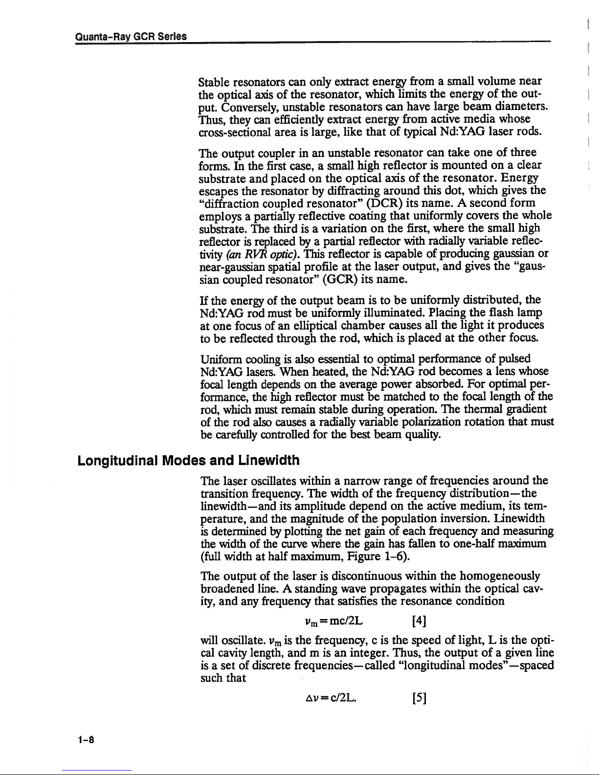
Figure
Single
An
in
an
1—6:
Line
etalon,
cavity
the
optional
introducing
lasing
the
ing
distance
over
tionship—is
Longitudinal
Modes
Frequency
which
in
is
order
Fabry-Perot
enough
threshold
which
inversely
/
/
-/
I
/
Distribution
frequency-selecting
a
to
reduce
the
interferometer
in
loss
(Figure
output beam
the
other
modes
1—7).
proportional
Longitudinal
of
element,
linewidth.
that
to
The
coherence
maintains
the
to
linewidth:
MHz
220
Spacing
Modes
must be
Spectra-Physics
asabandpass
acts
prevent
them
length—the
fixed
a
30GHz
Linewidth
for
inserted
utilizes
reach
from
phase
rela
a
filter,
Reducing
width
is
increases
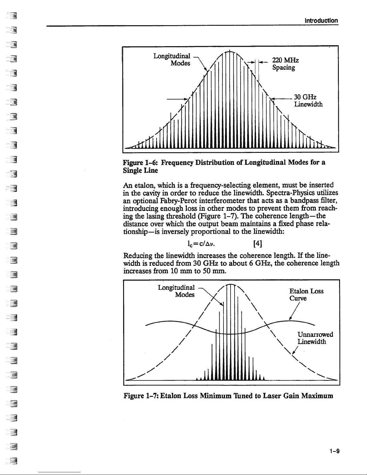
Figure
the
reduced
from
Longitudinal
Etalon
1—7:
1=
linewidth
from
10
mm
Modes
Loss
c/v.
increases
0Hz
30
to
50
Minimum
to
mm.
z
coherence
the
about
Tuned
\
6
[4]
0Hz,
to
length.
Laser
the
coherence
Gain
If
Etalon
Curve
Maximum
the
line-
length
Loss
1—9
Quanta-Ray
GCR
Series
Producing
Other
Wavelengths
peak
high
The
nonlinear
version
(KD*p).
interacts
fundamental
For
and
tion
wavelength
their
gating
length
propagate
most
Phase
crystal
axes
With
matching,
larized
wavelength
an
put
wavelength
matching
in
efficiency.
the
may
in
In
with
maximum
phase
most
of
index
waves.
matches
efficient
matching
and
the
of
KD*P
along
angle
between
remains
K1)*P
residual
yield
can
Type
power
simplest
the
crystal
the
wavelength.
efficiency
relationship
materials
longer.
gets
refraction
of
these
In
extraordinary
the
in
phase
and
under
critically
is
angle
the
crystal.
phase
two
input
the
extraordinary
the
linearly
the
polarized
elliptically
is
used
be
more
is
II
However,
nm
1064
better
overall
the
of
crystals
Q-switched
like
case
produce
to
waves
the
throughout
depends
However,
depends
materials,
the
at
“phase
these
dependent
between
matching
is
along
the
polarized.
extraordinary
along
the
polarized.
generate
to
widely
light
experiments
for
some
system
potassium
1064
the
secondary
a
must
crystal.
the
wavelength,
the
on
some
the
on
the
if
index
speed.
same
matching”
direction
the
alternatives
ordinary
This
axis.
In
Type
and
extraordinary
Although
second
the
because
used
highest
efficiency,
performance.
pulses
permit
dideuterium
Nd:YAG
nm
maintain
The
materials
polarization
ordinary
the
of
other,
Frequency
conditions.
temperature
the
on
polarization
of
exist.
and
axis,
leaves
the
input
LI
ordinary
axis.
either
harmonic
of
require
frequency
fundamental
with
wave
the
same
index
decreasing
birefringent:
are
of
index
of
the
conversion
In
Type
the
the
residual
polarization
axes,
residual
The
type
higher
its
and
Type
polarization
linear
phosphate
half
speed
refrac
of
propa
the
wave
one
waves
the
of
and
phase
I
output
input
phase
of
Nd:YAG
of
the
while
conversion
doubling
I
con
the
as
the
po
is
is
input
the
is
at
out
of
1—10
resultant
The
through
mixed
355
in
nm
—cover
ultraviolet,
the
and
532
and
355
studies
optical
These
of
modification
fixed
shifting
continuously
is
532
second
a
KD*P
wave.
the
with
These
electromagnetic
which
will
nm
355
266
nm
many
molecules.
frequencies
by
using
or
tunable
wave
nm
crystal,
the
four
enhances
pump
useful
are
of
them
be
can
which
residual
yields
1064
wavelengths—
spectrum
the
lasers
dye
for
dissociation
nm
1064
extended
be
pump
over
and
materials
can
to
output
doubled
266
a
nm
1064,
from
usefulness
with
266
and
probing
further
laser.
dye
a
wide
a
nm
by
wave.
again
fundamental
355,
532,
the
near
of
the
conversion
high
and
photodestructive
are
nm
of
semiconductors.
through
result
The
of
range
wavelengths.
passing
It
can
produce
to
and
infrared
Nd:YAG
efficiency.
widely
Raman
of
it
also
266
laser.
used
the
be
a
nm
to
for
latter
Introduction
Resonator
Structural
Considerations
The
stability
the
resonator
several
cause
length
where
the
eliminate
The
The
high
a
the
Graphite
have
structural
compensation
The
expansion
over
sources
corresponding
changes
is
L
the
resonator
frequency
choice
ideal
material
ability
length
negative
a
the
wide
lowest
of
composite,
material.
of
of
the
structure.
including
due
cavity
structure
of
materials
to
distribute
the
structure.
thermal
system
expansion
the
metal
range
oscillating
Small
temperature
changes
to
temperature
L=
length,
and
drift,
either
affects
has
both
heat
such
as
expansion
Since
of
its
of
the
of
parts,
temperatures.
frequency
changes
in
the
oLT
cisthe
T
is
c
the
low
a
evenly,
that
used
coefficient
resonator
the
graphite
so
the
depends
in
cavity
changes
resonant
can
be
expressed
[5]
thermal
temperature
or
T
must
length
thermal
coefficient
net
stability
expansion
causing
in
the
is
also
structure
rods
change
on
length,
and
mechanical
frequency.
expansion
change.
zero.
be
of
constant
a
OCR
offsets
series
of
any
negative,
can
be
the
remains
the
design
which
Cavity
as
coefficient
In
order
the
structure.
coefficient
zT
resonators,
currently
the
thermal
kept
simple.
positive
near
of
have
shifts,
of
to
and
along
used
zero
Frequency
resonator
movement
resonator
the
case
stability
structure.
of
cavity
structure
that
surrounds
also
depends
Modulation
mirrors,
or
acoustic
the
laser
can
on
due
be
noise.
helps
the
mechanical
“jitter,”
to
caused
Isolation
reduce
by
jitter.
rigidity
the
microphonic
external
the
of
of
shock
resonator
to
the
the
from
1—11
Quanta—Ray
Pulse
Triggering
GCR
Series
Sequence
and
__rn__
Timing
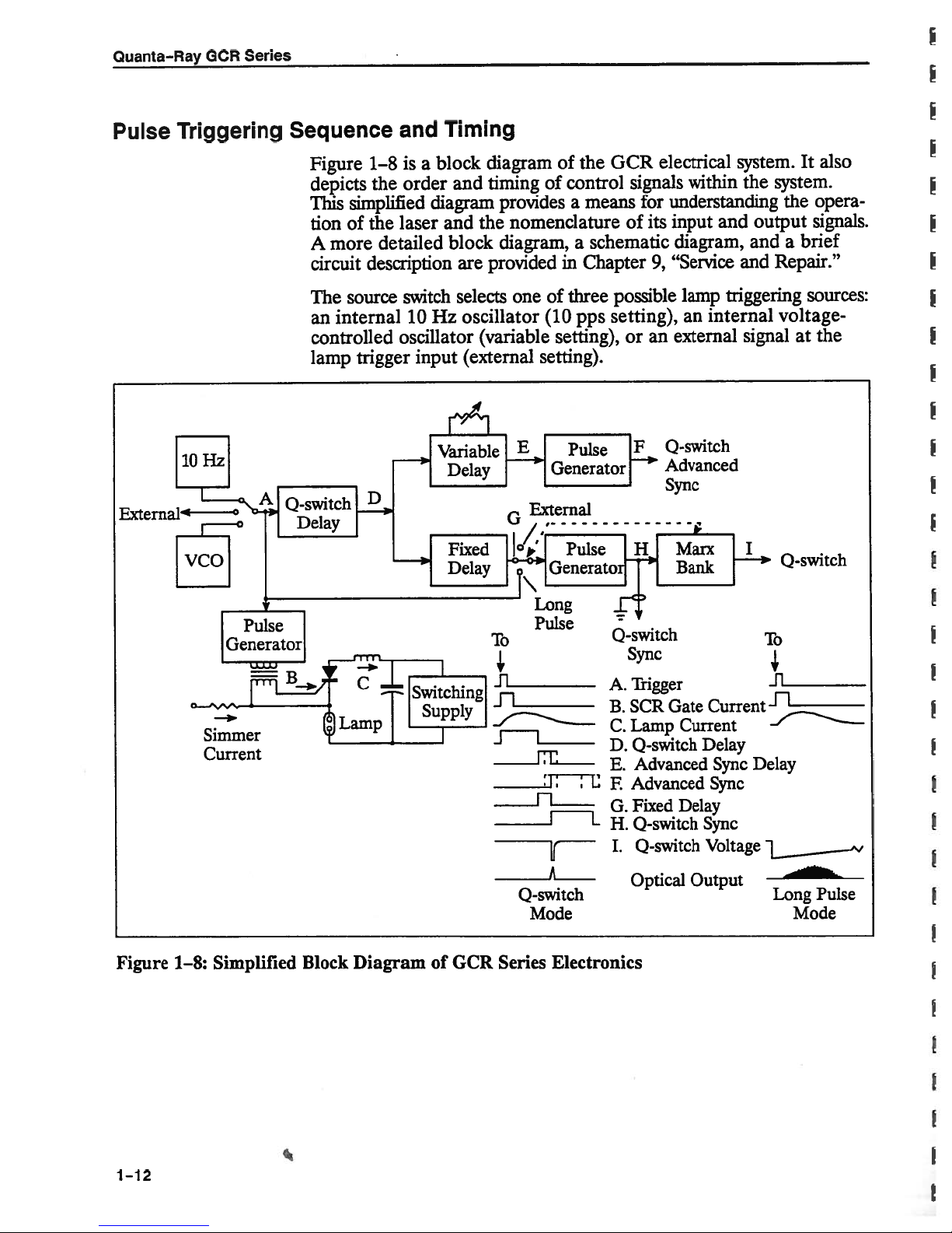
Figure
depicts
This
tion
A
circuit
The
an
controlled
lamp
1—8isa
the
simplified
the
of
more
description
source
internal
trigger
order
laser
detailed
switch
10
oscillator
input
block
and
diagram
the
and
block
are
selects
oscillator
Hz
(variable
(external
diagram
timing
provided
of control
provides
nomenclature
diagram,
one
of
(10
setting).
of
the
means
a
schematic
a
in
Chapter
three
pps
setting),
GCR
signals
for
of
its
9,
possible
setting),
or
an
electrical
within
understanding
input
diagram,
“Service
lamp
an
external
Advanced
Sync
system.
and
triggering
internal
It
the
system.
opera
the
output
and
and
signalatthe
signals.
brief
a
Repair.”
sources:
voltage-
0-switch
also
Figure
Simmer
Current
1—8:
Simplified
Block
Diagram
of
GCR
To
Ji
11
JL
Series
Pulse
A
0-switch
Mode
Electronics
0-switch
Sync
Trigger
A.
SCR
B.
Lamp
C.
D.
0-switch
Advanced
E.
Advanced
F
Fixed
G.
H.
0-switch
I.
0-switch
Optical
Gate
Current
Delay
Output
Current
Delay
Sync
Sync
Sync
Voltage
To
.fl_________
Delay
Long
Pulse
Mode
.4
1—12
Introduction
signal
This
the
fires
and
the
forming
pulse
rent
ingofthe
Nd:YAG
the
0
Pockels
mode
The
Pockels
triggering
long
pulse
system
In
the normal
(A)
SCR
0-switch
network,
(C)
Q-switch
rod.
of
the
cell.
switch
cell
pulseatthe
mode
alignment.
Subsequently,
nal
voltage
dation
total
The
delay
triggering
and
output
characteristic
delayofD
Q-switch
Signal
(D).
andavariable
The
variable
after
the
or
follows
end
the
advanced
the
post-trigger
the trigger
is
gate
delay.
whose
through
After
cavity
selects
be fired
can
that
mode,
the
the
of
+0.
advanced
D
delay
delay
of
the
sync
opening
pulse
current
generator
The
discharge
lamp.
the
until
the
approximately
to
maximum
the
internally
0-switch
provides
the
0-switch
pulse
generator
electro-optic
the
Marx
the
of
bank
Pockels
sync
triggers
(E),
pulse
fixed
pulse
with
both
setting
adjustable,
is
delay pulse.
generator
of
the
range
a
for
source
all
for
current
gate
SCR
produces
Q-switch
The
population
225
jisec,
applying
by
configuration
(normal
trigger
pulseoflow
a
input (external
delay
fired
is
driver
(I)
changes
cell,
is
up
the
also
fixed
race
a
signal
soitcan
The
(F),
whose
0-switch
of
(I).
±500
subsequent
the
pulse
(B)
a
critically
delay
inversion
its
high
of
the
mode),
peak
firesafixed
(D)
providing
(H),
(Marx
the
opening
derived
delay
between
variable
output
This
nsec.
functions.
forming network
the
fires
pulse
damped
prevents
built
has
output
voltage
0-switch.
up
(D)
increases
(I)tothe
The
externally
mode),
power
useful
delay
sync
a
bank).
The
polarization
the
0-switch
the
from
(G)
these
end
either
delay
creates
described
either
two
before
pulse
pre-
a
0-switch
precedes
It
cur
open
the
in
a
by
orina
for
(0).
sig
high
retar
after
above
pulses.
triggers
or
a
or
In
the
firing.
lamp
pulse
that
inhibited
long
pulse
It
yields
this
in
mode
is
internally
long
a
mode.
the
Pockels
charged
optical
cell
to
pulse.
triggered
is
provide
The
0-switch
a
4
long,
at
sync
the
high
moment
voltage
output
of
is
1-13
Quanta—Ray
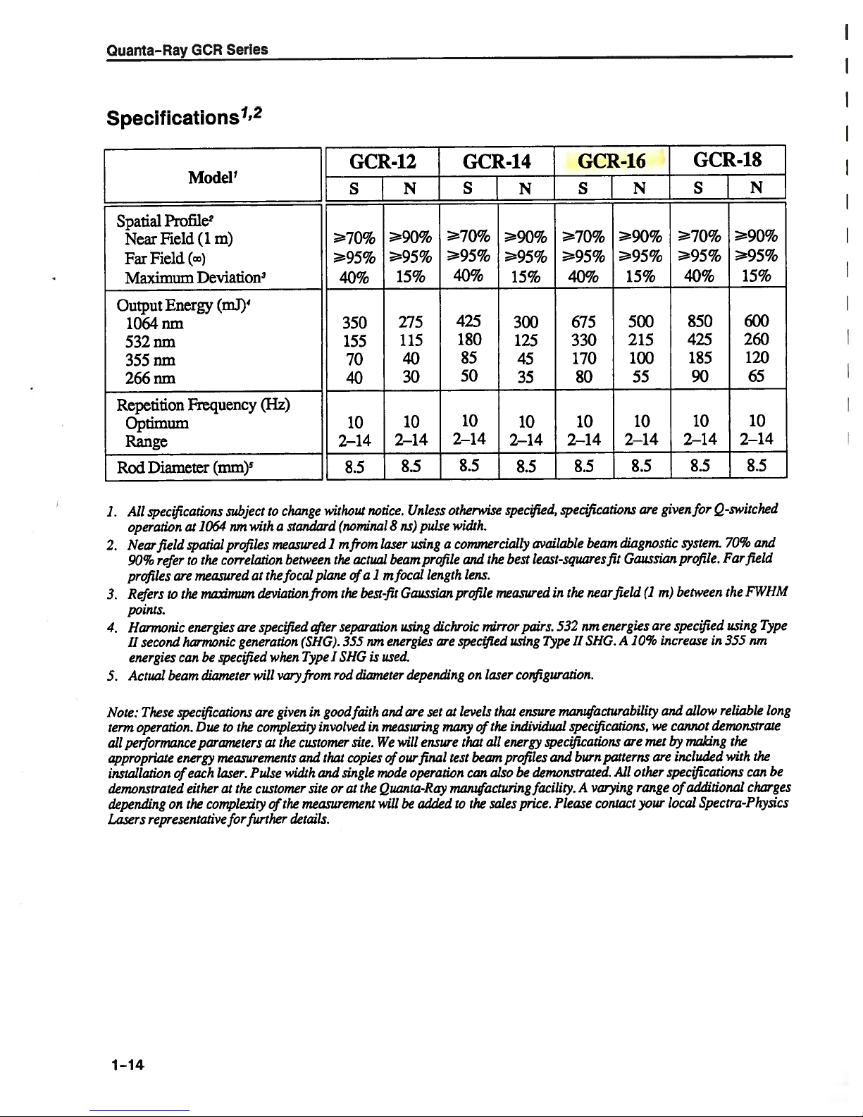
Specifications
1’2
GCR
Series
Spatial
Near
Field
Far
Maximum
Output
1064nm
532nm
355nm
266nm
Repetition
Optimum
Range
Diameter
Rod
All
specflcations
1.
operation
Near
2.
90%
profiles
Refers
3.
points.
Harmonic
4.
II
second
energies
Actual
5.
Profile
2
Field
Energy
as
field
refer
are
the
to
hannonic
can
beam
Model
1
(1
m)
(cc)
Deviation
3
(mJ)
4
Frequency
(mm)’
subject
1(364
nm
profiles
spatial
to
the
correlation
measured
maximwn
energies
are
generation
specfled
be
diameter
(Hz)
change
to
a
standard
with
measured1mfrom
between
focal
vary
plane
from
after
(SHG).
Type
from
at
the
deviation
spec(fIed
when
will
GCR-12
s{N
70%
95%
40%
350
155
70
40
10
2—14
8.5
without
notice.
(nominal8ns)
actual
the
of
a1mfocal
best-fit
the
separation
nm
355
is
I
SHG
diameter
rod
90%
95%
15%
275
115
40
30
10
2—14
8.5
Unless
using
laser
beam
Gaussian
using
energies
used.
depending
pulse
profile
length
dichroic
are
70%
95%
otherwise
width.
a
GCR-14
S
40%
425
180
85
50
10
2—14
8.5
commercially
and
lens.
profile
spec
on
9O%
95%
15%
300
125
45
35
2—14
8.5
specified,
the
best
measured
mirror
jfied
using
configuration.
laser
N
10
70%
95%
40%
675
330
170
2—14
specifications
available
least-squares
in
the
532
pairs.
Type
II
GCR-16
S(N
90%
95%
15%
80
10
2—14
8.5
diagnostic
beam
fit
Gaussian
field
near
energies
nm
A
SHG.
500
215
100
55
10
8.5
are
10%
given
(1
m)
are
increase
GCR-18
SjN
70%
95%
40%
850
425
185
90
10
2—14
8.5
for
Q-switched
system.
profile.
between
specified
in
90%
95%
70%
Far
the
using
355
15%
600
260
120
65
10
2—14
8.5
and
field
FWHM
Type
nm
given
Note:
term
performance
all
appropriate
installation
demonstrated
dependingonthe complexity
Losers
1-14
specifications
These
operation.
representative
Due
energy
each
of
either
parametersatthe
are
to
complexity
the
measurements
width
Pulse
laser.
at
customer
the
the
of
her
for
fun
good
in
involved
customer
and
that
single
and
oratthe
site
measurement
details.
faith
in
site.
copies
are
and
measuring
We
mode
Quanta-Ray
will
of
will
our
be
set
ensure
final
operation
added
levels
that
beam
can
the
to
of
that
the
all
also
sales
energy
profiles
at
many
test
manufacturing
manufacturability
ensure
individual
specifications
and
demonstrated.
be
facility.
price.
Please
and
allow
specflcations,wecannot
burn
A
are
patterns
All
varying
contact
other
range
your
maldng
met
by
included
are
specflcations
additional
of
local
reliable
demonstrate
Spectra-Physics
the
with
long
the
can
be
charges
X
1064nm
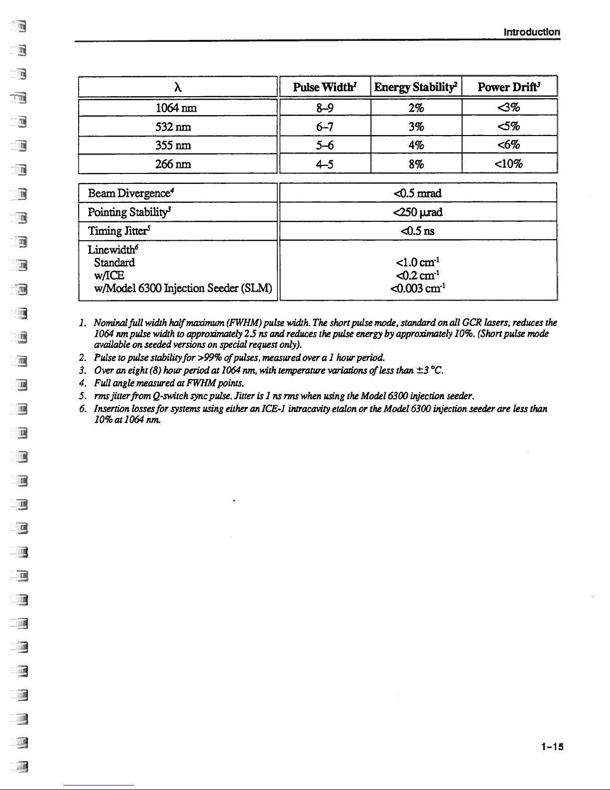
Pulse
Width
1
8-9
Energy
Stability
2
2%
{
Power
<3%
Introduction
Drift
3
Beam
Pointing
Timing
Linewidth
6
Standard
w/ICE
w/Model
1.
Nominalfull
1064
available
Pulse
2.
Over
3.
4.
Full
nnsfltterfrom
5.
Insertion
6.
10%
Divergence
4
Stability
3
Jitter
5
6300
width
urn
pulse
width
on
seeded
pulse
eight
(8)
measured
losses
nm.
stabilizyfor
Q-,switch
to
an
angle
at1064
532nm
355nm
266nm
Injection
half
to
versions
hour
at
for
systems
Seeder
on
>99%
at
pulse.
using
(FWHM)
special
of
1064
points.
either
maximum
approximately
period
FWHM
rync
(SLM)
2Susand
request
pulses,
nrn,
Jitter
an
pulse
only).
measured
with
temperature
is
1
ns
ICE-i
6—7
5—6
4-5
width.
The
reduces
over
when
rms
intracavity
short
the
pulse
1
hour
a
variations
using
the
etalonorthe
pulse
energy
period.
Model
mode,
less
of
<250
<0.003
by
6300
Model
3%
4%
8%
mrad
<0.5
I.Lrad
ns
<0.5
<1.Ocnr’
cm-
1
<0.2
cm’
standard
approximately
than
on
±3°C.
injection
6300 injection
GCR
all
10%.
seeder.
lasers,
(Short
seeder
<5%
<6%
<10%
reduces
pulse
are
less
the
mode
than
1-15
Quanta-Ray
GCR
Series
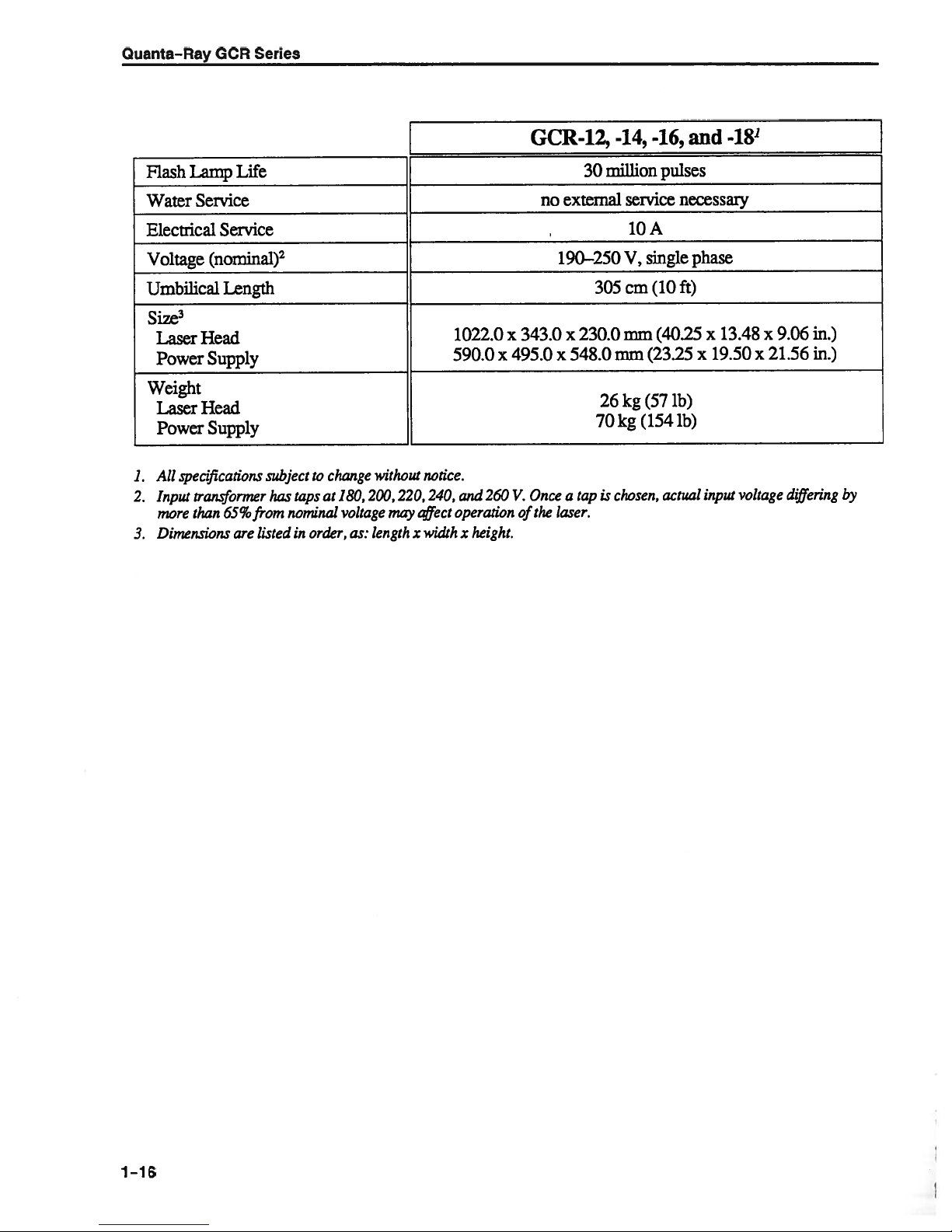
GCR-12,_-14,
-16,
and
-18
Flash
Water
Electrical
Voltage
Umbilical
Size
3
Laser
Power
Weight
Laser
Power
All
specflcations
1.
2.
Input
more
Dimensions
3.
Lamp
Life
Service
Service
(nominal)
2
Length
Head
Supply
Head
Supply
transformer
than
65%
are
subject
has
from
listed
to
change
taps
at
nominal
order,
in
may
notice.
t’4ject
width
x
without
180,200,220,240,
voltage
length
as:
1022.0
x
590.0
260
and
operation
x
height.
no external
x
343.0
495.0
Once
V.
the
of
million
30
190—250
305
x
230.0
x
548.0mm
26
70
tap
is
a
laser.
chosen,
service
10
single
V,
cm
mm
(23.25
kg
(57
(154
kg
pulses
necessary
A
(10
ft)
(40.25
ib)
ib)
actual
phase
x
13.48
19.50
x
input
x
21.56
x
voltage
9.06
differing
in.)
in.)
by
1-16
Chapter
2
Laser
Safety
Precautions
of
Class
for
IV-High
the
Power
•
•
•
•
•
•
•
•
•
•
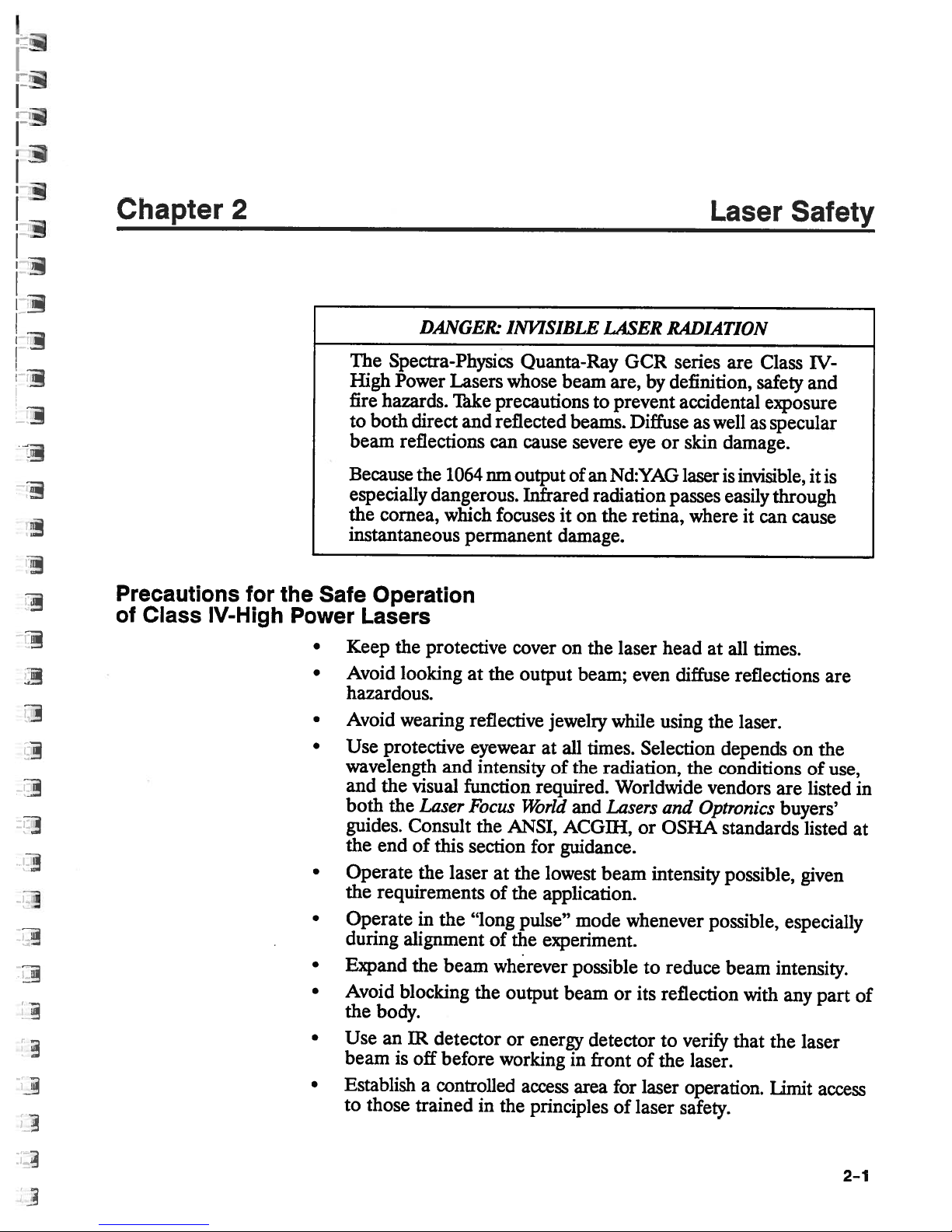
The
High
fire
to
both
beam
Because
especially
the
instantaneous
Safe
Operation
Lasers
Keep
Avoid
hazardous.
Avoid
Use
wavelength
and
both
guides.
the
end
Operate
the
requirements
Operate
during
Expand
Avoid
the
body.
Use
beam
Establish
to
those
DAJ’JGER.
Spectra-Physics
Power
hazards.
reflections
cornea,
the
looking
wearing
protective
the
the
blocking
an
is
Lasers
Take
direct
visual
and
the
1064
dangerous.
which
permanent
protective
and
function
Laser
Consult
of
this
the
laser
in
the
alignment
the
beam
IR
detector
off
before
a
controlled
trained
at
reflective
eyewear
intensity
Focus
the
section
“long
the
in
INVISIBLE
Quanta-Ray
whose
precautionstoprevent
reflected
cause
can
nm
output
Infrared
focuses
cover
the
output
jewelry
at
of
required.
World
ANSI,
for
the
at
of
of
wherever
working
the
pulse”
the
output
or
energy
access
the
principles
lowest
application.
experiment.
LASER
beam
it
damage.
on
all
ACGIII,
guidance.
beam
are,
beams.
severe
of
an Nd:YAG
radiation
on
the
the
laser
beam;
while
times.
the
radiation,
Worldwide
and
Lasers
beam
mode
possible
or
detector
in
front
area
for
of
GCR
Diffuse
eye
retina,
even
whenever
its
of
laser
RADIATION
series
by
definition,
accidental
as
or
skin
laser
passes
where
head
diffuse
using
Selection
the
and
Optronics
or OSHA
intensity
reduce
to
reflection
verify
to
the
laser.
laser
operation.
safety.
are
Class
safety
well
as
damage.
is
invisible,
easily
it
can
at
all
times.
reflections
the
laser.
depends
conditions
vendors
standards
possible,
possible,
beam
with
that
IV-
and
exposure
specular
it
through
cause
on
the
of
listed
are
buyers’
listed
given
especially
intensity.
any
part
the
laser
Limit
access
is
are
use,
in
at
of
2—1

Quanta—Ray
GCR
Series
Maintain
•
the
so
damage.
prominent
Post
•
up
Set
•
level.
eye
Provide
•
up
Set
•
up
Set
•
preventing
of
Use
other
ation
Follow
your
of
your
of
ation*
ance
than
exposure.
the
laser.
laser,
that
Standards
Regulations,
high
a
eye’s
ambient
pupil
warning
experiments
enclosures
shields
an
to
energy
unnecessary
those
or
specified
controls
instructions
all
At
avoid
exceeds
times
unnecessary
the
for
Laser
21CFRI.040
light
remains
signs
the
so
for
beam
prevent
unnecessary
absorbing
reflections
CAUTION
adjustments,
herein
contained
during
accessible
Products,”
10(d).
level
constricted,
the
near
beam
laser
paths
target
whenever
to
or
or
performance
may
this
in
operation,
exposure
emission
United
laser
the
in
reducing
laser
either
is
specular
capture
scattering.
result
manual
maintenance,
laser
to
limits
States
operation
the
operation
above
possible.
reflections.
laser
the
of
in
hazardous
safe
for
collateral
or
listed
Code
area
possibility
area.
below
or
beam,
procedures
radi
operation
service
or
“Perform
in
Federal
of
of
radi
Focused
Back
*
Any
a
as
Reflection
Focused
energyofany
illustrate,
To
of
4%
tion
second
enough
laser.
the
to
damage
avoid
To
put
beam,
the
optical
The
back
electronic
result
Safety
back
the
the
off
focuses,
to
damage
OCR
reflections.
product
or
of
reflections
OCR
consider
energy
first
destroy
Even
optical
and
axis.
necessary
where
warranty
radiation,
for,
the
of
series
laser
an
uncoated
incident
surface
and
the
antireflection
components
to
diverges
power
the
Q-switch,
your
laser,
they
does
except
operation
even
can
eachofits
on
density
Nd:YAG
coated
of
minimize
are
unavoidable,
WARNING
not
radiation,
laser
laser
a
of
a
small
percentage
destroy
convex
surfaces.
harmlessly,
the
at
optics
laser.
the
back
cover
damage
emittedbya
incorporated
optical
its
which
lens,
the
point
and
rod,
reflect
can
reflections
direct
caused
loser
into
the
of
components.
reflects
of
focus
output
enough
by
the
away
While
reflection
them
product
product.
that
output
about
reflec
off
high
is
coupler
energy
its
of
from
focused
p
the
of
out-
2-2
p
p

Laser Safety
Maintenance
in
Compliance
logical
Health
Required
with
Center
(CDRH)
This
Federal
1040.11,
of
has
flood,
on
1.
2.
3.
4.
5.
6.
to
keep
for
Regulations
laser
product
Regulations,
applicable.
as
features
all
been
subjected
mechanical
radiation
the
Verify
operation.
Verify
ON
switchisin
Verify
a
Verify
and
action to
Verify
Verify
mechanism
until
that
that
position,
that
visible
the
starting of
that
that,
disengaged.
this
Devices
complies
listed
shock,
control
removing
the
and
the
the
signal
time
avoid
removing
when
clearly
is
and
with
maintain
To
either
spilled
drawing
the
will
the
position.
between
laser;
the
cover
visible
Product
Radio
Title
1,
SubchapterJ,Parts
environmental
solvents).
(Figure
remote
only
key can
indicator
the
it must
cover
interlockisdefeated,
and
Laser
Chapter
below,
adverse
to
laser
that
OFF
emission
whenever
delay
the
exposuretolaser
the
21ofthe
compliance,
annuallyorwhenever
2—1).
interlock
operate
laserison.
turn-on
shuts
prevents
with
only
works
give
enough
radiation.
off
United
verify
conditions
The
features
plug
the
key
be removed
properly;
of
the
emission
warningtoallow
the
laser.
installation
1040.10
prevents
States
the
the
(e.g.,
are
switch
when
that
the
of the
Code
and
operation
product
fire,
identified
laser
the
in
the
is,itemits
indicator
defeat
cover
of
the
laser
Both
operatingatlethal
turn
off
the
protective
after
powerisoff,
before
If
tremely
components.
Allow
ics,
repair
Disconnect
ponents
power
you
and
touching
must
carefultoavoid
only
who
the
to ground
supply.
head
laser
covers.
have
those
understand
laser.
the
power
DANGER:
and
voltage
and
disconnect
After
short
them.
the
covers
trainedinhigh
line
where
HIGH
power
and
waiting
high
off
contact
the
circuitry
and
appropriate,
VOLTAGE
supply
current
the power
at
least1mm
voltage
while
with
voltage,
short
high
contain
levels.
components
operating
high voltage
ofthe
before
electrical
Whenever
line
before
for
the laser,
high
current
OCR,toservice
voltage electrical
working
circuits
possible,
removing
bleed
ground
to
terminals
electron
on
down
be
ex
and
and
com
the
2-3

Quanta—Ray
GCR
Series
Sources
of
Laser
Safety
“Safe
American
11th
New
Tel:
“A
American
Industrial
6500
Cincinnati,
Tel:
Occupational
U.S.
200
Washington,
Standards
Use
West
York,
(212)
Guide
Glenway
(513)
Department
Constitution
(202)
Tel:
Lasers”
of
National
Street
42nd
10036
NY
642—4900
Control
for
Conference
Hygienists
Avenue,
45211
OH
661—7881
Safety
of
Avenue
20210
DC
523—8148
(Z136.1)
Standards
Laser
of
Governmental
of
(ACGIH)
Bldg.
Health
and
Labor
N.W.
Institute
(ANSI)
Hazards”
D-7
Administration
and
(OSHA)
2-4

/
,,—
Protective
Interlock
Housing
(Far
Side)
Aperture
Label
Laser
Safety
Interlock
Label
Certification
Identification
Protective
(Far
11111
IIIININIIIIIIIIII
and
Label
Side/Back)
‘Naming
Logotype
Housing
iZ7
Interlock
H
Emission
Indicator
Th
0
INIIIIIIIIIIIIIIIIIIIII
[
lull
ulIIlllIullIllIllIllllll
r
0
11111
0
Key
Activated
Control
Master
E
0
“ON”
Emission
I
r
Indicator
Lamp
Remote
Interlock—j-”-
Connector
(Far
Side/Back)
Figure
2—1:
Radiation
Control
Drawing
2—5

Quanta-Ray
GCR
_______
Series
SPECTRA-PHYSICS
1330
TERRA
MTN.
VIEW,
MANUFACTURED:
MONTH
MODEL
ThIS
LASER
21
CFR
MADE
PRODUCT
WITh
Certification
Identification
DANGER
VISIBLE
RADIATiON
LASER
I
AND
INTERLOCK
I
AVOID
EYE
I
TO
DIRECT
I
LON
Interlock
DELLA AVE.
CA
94043
1
D40
AS
IN
AND
INVISIBLE
OR
SKIN
SCATTERED
OR
YR
SIN_______
COMPUES
APPUCABLE
U.S.A.
and
Label
WHEN
OPEN
DEFEATED
EXPOSURE
Label
INC.
AIBtS
EMITTED
[AVOID
Aperture
•
SEE
AVOID
DIRECTORSCATTERED
UANLIA.
Warning
AND
INVISIBLE
ER
RADIATION
FROM
ThIS
APERTURE
EXPOSURE]
Label
LASER
SKIN
a
IV
LASER
INVISIBLE
&
RADIATION
EXPOSURE
Nd/1.5J/10
VISIBLE
EYE
CLASS
Logotype
.
TO
RADIATION
PRODUCT
k
Figure
2—2:
Warning
Labels
2—6
Chapter
3
Installation
and
Operation
Unpacking
Installing
your
the
Laser
Laser
OCR
Your
arrive
Inspect
damage.
carrier
the
Physics
claim.
your
Keep
show
to
service,
for
following
The
is
not
laser.
tion
appointment,
only
those
up
set
series
damaged,
unit
each
If
you
and
will
correct
the
shipping
shipping
that
these
intended
Please
your
call
qualified
laser
was
laser
the
have
as
you
discover
notify
installation
asaguide
your
the
crates.
special
your
which
problem
caused
service
and
system.
carefully
shipper’s
unpack
any
damage,
it:
look
Spectra-Physics
without
you
If
damage.
the
crates
is
authorized
provide
procedure
to
initial
the
representative
of
part
CAUTION
your
present
for
for
dents,
packed
agent
immediately
representative.
waiting
file
claim,
a
If
you
maximum
is
provided
installation
purchase
Spectra-Physics
by
shipment;
for
you
must
for
arrange
to
file
you
claim
a
when
scratches,
settlement
will
need
return
protection.
reference
set-up
and
an
agreement.
to
if
its
crates
unpack.
or
other
against
Spectra-
of
them
the
only;
of your
installa
Allow
install
unit
it
and
the
Connecting
Electrical
1.
2.
of
Use
dures
controls
other
radiation
Service
main
The
most
of
the
with
the
green
marked
transformer
that
range
Connect
sure
or
adjustments
than
those
exposure.
autotransformer
a
different
is
closely
OCR
the
power
171
wire
252
to
matches
is
±5%
cord
is
specified
(Figure
operating
Connect
V.
available
of
this
the
to
connected
or
herein
3—1)
voltage.
voltage.
power
to
performance
result
may
several
has
The
black
the
voltage.
line
circuit
line
earth
ground,
proce
of
hazardous
in
taps,
rangeofthe
the
to
wire
operating
The
breaker;
not
neutral.
each
auto-
tap
be
3-1
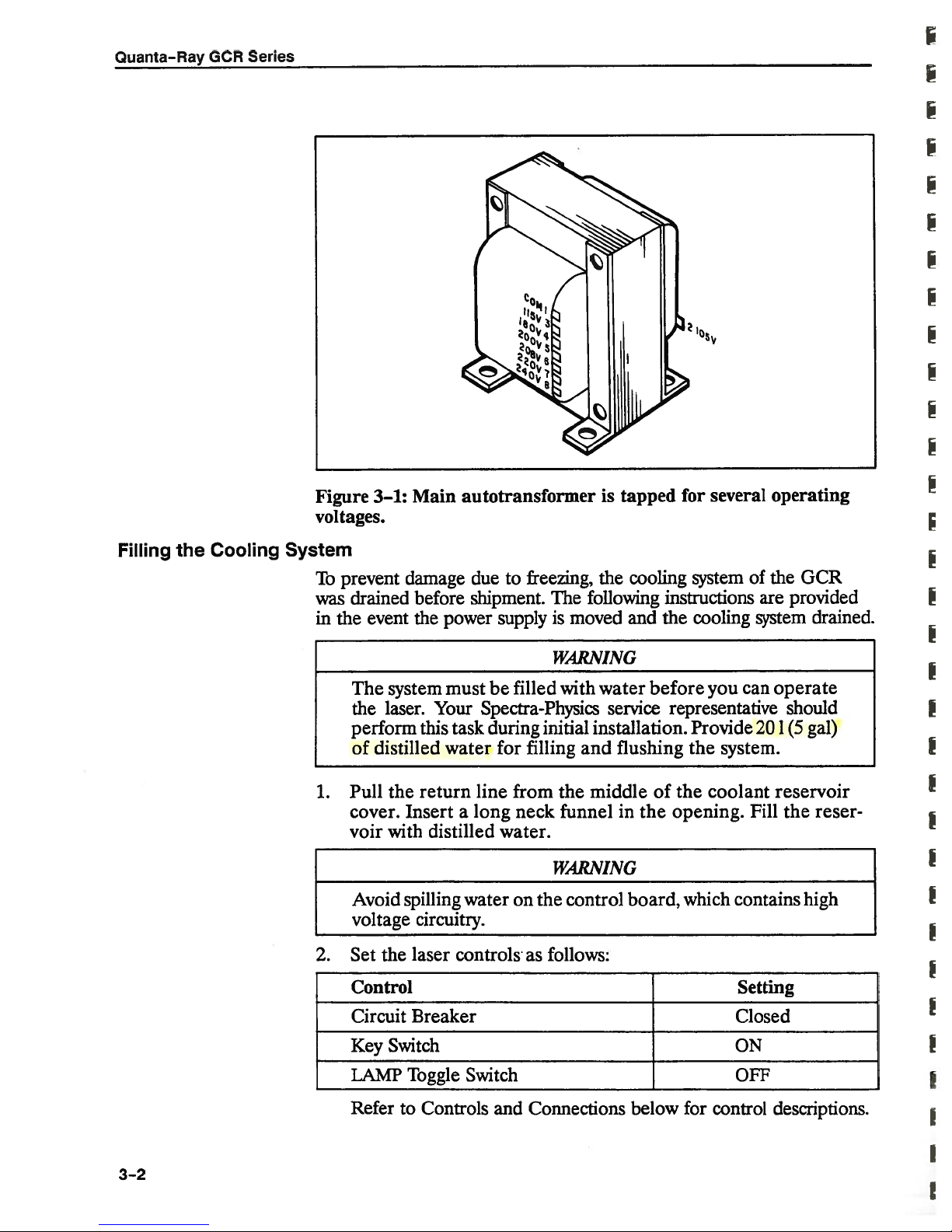
Quanta—Ray
GCR
Series
Filling
the
Cooling
Figure
voltages.
System
To
was
in
1.
3—1:
prevent
drained
event
the
The
the
perform
distilled
of
Pull
cover.
voir
Avoid
voltage
Main
damage due
before
power
the
Your
this
must
task
system
laser.
water
the
return
Insertalong
with
distilled
spilling
circuitry.
autotransformer
freezing,
to
shipment.
The
supplyismoved
WARNING
filled
be
with
Spectra-Physics
during
line
initial
for
filling
from the middle
funnel
neck
water.
WARNING
wateronthe
control
is
tapped
cooling
the
following
and
water
service
installation.
and
flushing
in
the
board,
several
for
system
instructions
the
cooling
before
you
representative
Provide
the
system.
of
the
coolant reservoir
opening.
which
operating
of
the
are
system
can
operate
201(5
Fill
the
contains
OCR
provided
drained.
should
gal)
reser
high
2.
3—2
the
laser
controls
as
follows:
Set
Control Setting
Circuit
Key
LAMP
Refer
Breaker
Switch
Toggle
to
Controls
Switch
and
Connections
below
Closed
ON
OFF
for control
descriptions.
p
p

Installation
and
Operation
Controls
and
Figure
3.
4.
3—2:
Hold
the
reservoir,
Shut off
return
the
ON
line
Cooling
coolant
button
keeping
laser,
the
back
Connections—Remote
SIMMER
LAMP
calibrated
is
Q-SWitch
range
VARIABLE
approximately
indicator—glows
ENERGY
is
150—550
control—sets
lamp
in
DELAY
control—sets
1—15
System
return
to start
it
into
the
full,
then
the
Component
line
cooling
until
fill
the
hole
Control
when
the
joules
control—adjusts
psec;
pps.
(U).
the
surrounding
the
variable
over
a
system
water
reservoir
the
of
Module
the
flash
energy
the
lamp
Identification
drain
or bucket,
pump.
from
flows
to
capacity.
reservoir
lamp
simmer
of
the
flash
timing
scale
of
is
firing
Q-switch
relative.
rate;
Md
return
the
cover.
current
lamp;
then
water
Shove
the
press
to
line.
the
is
its scale
firing.
range
the
on.
The
is
3-3
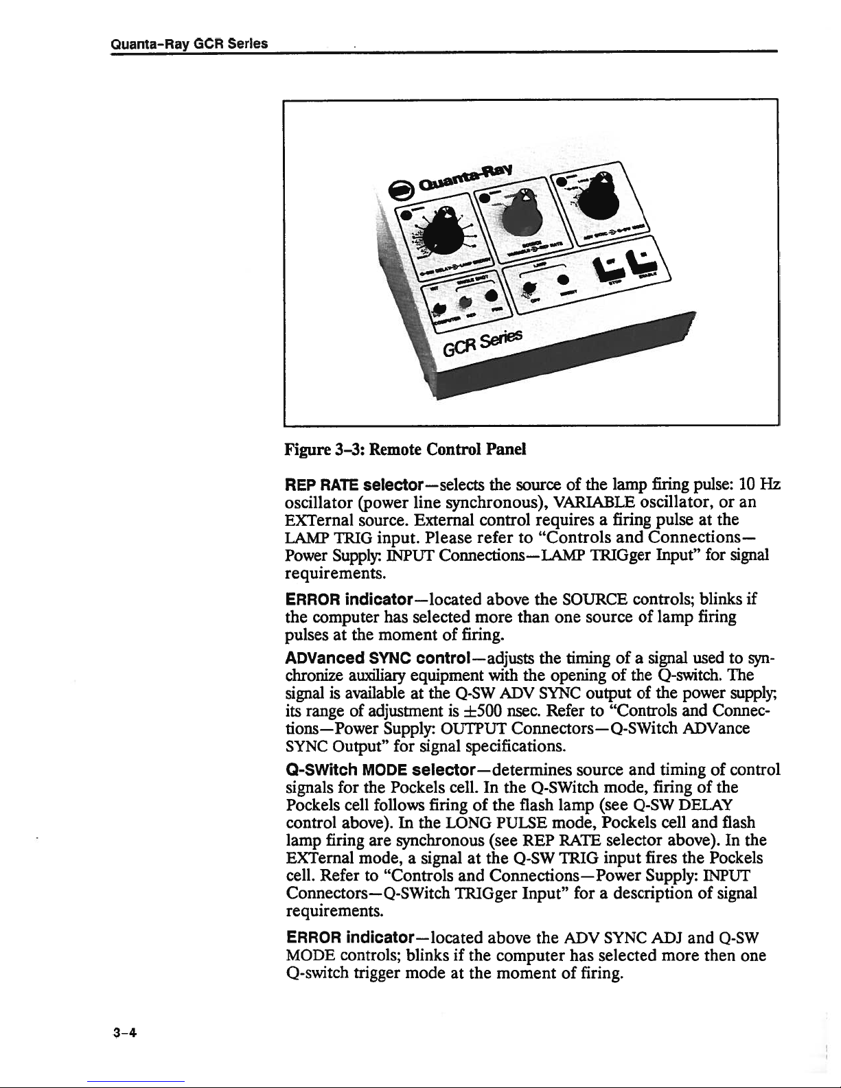
Quanta-Ray
GCR
Series
3—3:
Figure
RATE
REP
oscillator
EXTernal
LAMP
Power
Remote
selector—selects
(power
source.
TRIG
Supply:
input.
INPUT
requirements.
ERROR
the
pulses
ADVanced
chronize
signal
its
tions—Power
SYNC
0-SWitch
signals
Pockels
control
lamp
EXTernal
cell.
indicator—located
computer
the
at
SYNC
auxiliary
available
is
range
of
adjustment
Output”
MODE
for
the
cell
follows
above).
firing
are
mode,
Refer
to
has
moment
Supply:
“Controls
Connectors—Q-S
requirements.
Control
Panel
the
line
synchronous),
External
Please
control
refer
Connections—LAMP
above
of
more
firing.
selected
control—adjusts
equipment
the
at
0-SW
is
±500
with
OUTPUT
for
signal
specifications.
selector—determines
In
firing
the
signal
Witch
cell.
of
LONG
at
and
TRIGger
the
(see
the
Connections—Power
Pockels
In
synchronous
a
source
the lamp
of
VARIABLE
requires
to
“Controls
the
SOURCE
than
one
timing
the
opening
the
ADV
SYNC
Refer
nsec.
Connectors—Q-S
source
Q-SWitch
the
lamp
flash
REP
0-SW
Input”
mode,
RATE
TRIG
for
PULSE
a
firing
and
TRiGger
source
of
of
output
“Controls
to
mode,
(see
Pockels
selector
input
a
description
pulse:
firing
oscillator,
pulse
Connections—
Input”
controls;
lamp
of
a
the
of
signal
used
Q-switch.
power
the
and
Witch
and
ADVance
timing
firing
Q-SW
DELAY
cell
and
above).
the
fires
Supply:
or
the
at
for
blinks
firing
The
Connec
of
of
the
flash
In
Pockels
INPUT
signal
of
Hz
10
an
signal
if
syn
to
supply:
control
the
3-4
ERROR
MODE
Q-switch
indicator—located
controls;
trigger
blinks
mode
at
if
above
the
the
the
computer
moment
ADV
has
of
firing.
SYNC
selected
ADJ
more
and
Q-SW
then
one

installation
and
Operation
Controls
SINGLE
lively
tion
the
single
firing
COMPUTER/INTernal
trol
when
restored
LAMP
lamp
indicator
OFF
cator,
ON
circuit
serves
Connections—Power
and
SHOT
or
in
(down),
SINGLE
pulse
signal,
module
the laser
by
switch—determines
single
the
SHOT
that
regardless
or
a
is
switching
switch—turns
to
fire.
If
the
will
glow.
button—turns
glowing
whenever
button—starts
breaker
is
asanemission
pulses
REP
on command.
RATE
position
synchronous
is
of
its
toggle
computer
under
computer
ittoINTERNAL.
on
the
switch
off
is
the
the power
the
laser;
closed
and
indicator,
Supply
whether
selector
(up),
pressing
with
controls
the
source.
switch—selects
as
controller.
control,
switching
OFF,
the
lamp
laser.
The
supply
only
operates
the
key
switch
glowing
When
the FII.E
next
This
so
power
button
is
whenever
the
in
the
available
either
switch
manual
supply,
is
off,
serves
on
after
is
turned
laser
the
REPetitive
firing
button
remains
allowing
and
asapower
the
but
the
power
the
will
rate.
flash
the
remote
control
INHIBIT
the
laser
on.
The
laser
repeti
fire
posi
When
triggers
lamp
active
can
the
is
supply
button
is
on.
in
a
con
be
flash
indi
off.
OUTPUT
INPUT
Connectors
Connectors
LAMP
Pulse
(p-p)
0-SWitch
SYNC (BNC)
width
when
loaded
SYNC
Q-switching
amplitude
mately
0-Switch
either
20
nsec.
in
advance
of2V
ADVance
approximately
amplitude
mately
0-SWitch
(Zm
delay
LAMP
flash
20 nsec.
=
16
is
required.
TRiGger
lamp
of
TRiGger
k).
(Z
—provides
is
approximately
with
(BNC)
of
the
laser.
(p-p)
SYNC
or
slightly
V
nsec.
(p-p)
±500
2
(BNC)—accepts
The
circuit
(BNC)—accepts
=
16
k2).
a
pulse
2.5
50
.
Rise
—provides
Pulse
width
when
loaded
(BNC)—provides
after
Pulse
width
when
loaded
is
overload
a5V
The
circuit
msec
time
a
with
firing
with
pulse
is
is
a5V
synchronous
having
an
amplitude
approximately
is
synchronous
approximately
2;
the
Q-switch.
rise
a
pulse
50
of
approximately
.
signal
Rise
to
50
protected.
signal
is
to
overload
externally
with
lamp
of2V
20
nsec.
with
5
msec
with
timeisapproxi
that
appears
The
range
5
msec
time
is
approxi
fire
the
Q-switch
An external
fire
protected.
firing.
with
time
the
an
is
an
3—5

Quanta-Ray
GCR
Series
:...
IuhIIIIIIIIIIIlIIIIIIlI
•
.
IIIlIIIIIIIIIIlIIIIIIIh
:
.
pIaI,iiat.i..*at.
IhnhI1IlIlllhlllll
liii;
11111
REMOTE
COMPUTER
POWER
Connector
Controls
Connector
Figure
ANALOG
information
circuitisoverload
data
transfer.
fires.
mode.
for
Accepts
Access
Circuit
switch,
Key
cuit
control
panel
3—4:
Power
STROBE
from
transfer.
This
Please
details.
to
Breaker—applies
and
Switch—applies
breaker
module
glows
Shorting
This allows
function
refer
37-pin
a
the
basic
all
110
and
when
Supply
(BNC)—a
the
protected.
analog
may
to
“D”
computer
V
key
will
operate.
power
Control
5
V
remote
the
Chapter
connector
convenience
power
switch
control
The
BNC
programming
be
operated
port;
powertopower
to
must
The
is
applied
Panel
signal
module
port
is
connector
inalevel
4,
‘Analog/TrL
from
the
50-pin
receptacles.
the
control
turned
be
lamp
OFF
but
enables
(Z
wired
to
be
to
remote
“D”
supply
electronics.
on
on
the laser
transmission
=
16
high
which
ground
done
or
Computer
connector.
before
the
stops
before
edge
control
circuitry,
remote
is
off.
triggered
the
of
kfl).
allows
data
the
Interface,”
cable.
the
Both
the
remote
control
analog
The
laser
key
cir
3-6

Installation
and
Operation
PURGE
Controls
INTERLOCK
which
sor,
supply
switches.
laser
cooling
ant
the
zero
PUMP
Flow
for
purge
comprises
auxiliary
cover
When
is
off,
water
pump,
laser.
clearing
To
LI)
(0
ON—starts
meter—monitors
normal
system
NITROGEN
purge
ble
pump
of
regulating
Desiccant
mounted
tal
row
consumed,
from
the
right
oil
filter,
color,
section.
than
of
left
i.e.,
At
1000
behind
ventilating
its
to
as
and
when
a
hrs
FAULT
the
interlock,
interlock
the
INTERLOCK
the
flowisshut
this
restart,
wait
and
the
operation.
and
starting
IN—fitting
when
using
under
condition
the
color
right,
the
the
cartridge
the
particle
the
flow
rate
under
lamp—indicates
switching
laser
switch,
circuit
supply
head
and
breaker
FAULT
off.
Pressing
interlock
clear
for
the
air
purge
Allow
for
external
1
the
purge
the
an
psi
fault,
time
system.
gas
about
laser.
external
should
fault.
delay
gas.
monitor—the
control
holes
changes
boundary
pink
of
conditions
panel,
above
from
ages.
filter
portion
0.25
between
Change
when
reaches
scf/h,
of
the
status
flow
water
two
and
lamp
then
air
laser
key
the
An
to
sensor,
temperature
head
switches
will
ON
interlock
turn
the
actuate,
flow.Itshould
mm
10
between
nitrogen
pressure
A
be
used
on
desiccant
can
be
seen
the
flow
meter.
blue
moderate
all
the
pink.
to
the
the
desiccant
of
the
the
cartridge
humidity.
colors
white
of
the
interlock
water
sensor,
cover
are
glow
because
button
fault
LAMP
about
be
set
turning
supply.
control
the
nitrogen
cartridge,
through
As
the
Since
the
will
cartridge,
desiccant
molecular
should
flow
interlock
on
but
starts
shuts
ENERGY
10
at
0.25
on
Turn
valve
which
the
desiccant
gas
progress
has
last
loop,
sen
power
the
the
the
cool
off
sec.
scf/h
the
off
the
capa
source.
is
horizon
flow
to
the
changed
sieve
more
to
is
is
Power
Supply
Rear
Panel
Convenience
sories,
the
Remote
e.g.,aswitch
shuts
interlocks
from
If
e.g.,
power
off
ground.
Accidental
the
age
no
remote
receptacle—provides
a
dye
supply
interlock
mounted
the
laser
using
grounding
laser
interlock
pump.
circuit
breaker
plug—allows
on
if
the
door
a
shielded
circuitry.
is
Maximum
useofother
the
doorofthe
opens
pair
of
WARNING
through
used,
install
110
power
energizes
while
twisted
the
remote
a
jumper
V
for
available
the
safety
laser
the
laser
wires
interlock
relay
control
is
10W.Closing
receptacle.
interlock
operation
is
on.
that
are
will
to
close
the
of
devices,
area
Wire
remote
isolated
dam
circuit.
acces
that
3-7
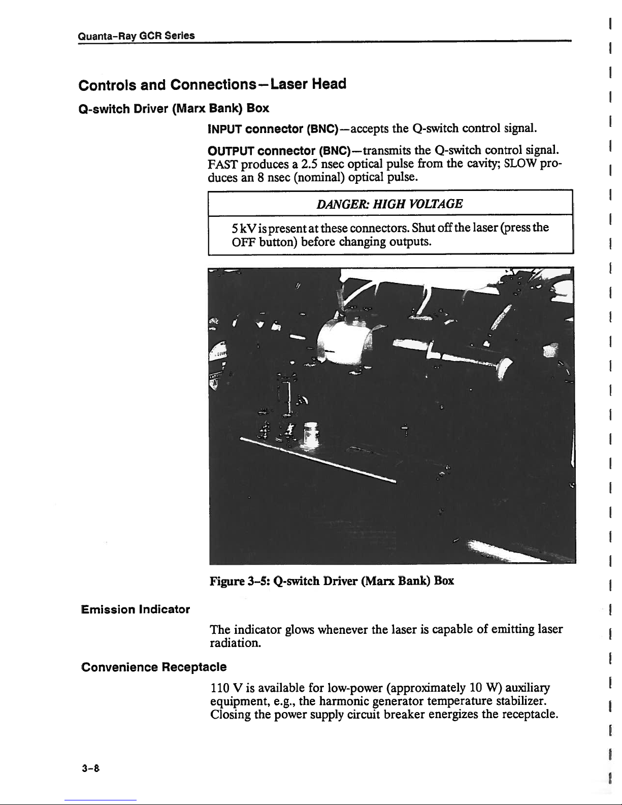
Quanta-Ray
GCR
Series
Controls
0-switch
and
Driver
Connections—Laser
(Marx
Bank)
INPUT
OUTPUT
FAST
duces
Box
connector
connector
produces
an
8
is
kV
5
OFF
nsec
present
button)
Head
(BNC)—accepts
(BNC)—transmits
optical
nsec
a
2.5
these
changing
optical
connectors.
(nominal)
DANGE&
at
before
the
pulse
pulse.
HIGH
outputs.
Q-switch
the
Q-switch
the
from
VOLTAGE
the
off
Shut
control
control
cavity;
laser
signal.
SLOW
(press
signal.
pro
the
Emission
Convenience
3-8
Indicator
Receptacle
Figure
The
3—5:
indicator
radiation.
V
is
110
equipment,
Closing
the
Q-switch
glows
available
e.g.,
power
whenever
for
the
harmonic
supply
Driver
(Marx
low-power
circuit
Bank)
is
laser
the
(approximately
generator
breaker
Box
capable
of
10
temperature
energizes
emitting
auxiliary
W)
stabilizer.
the
receptacle.
laser
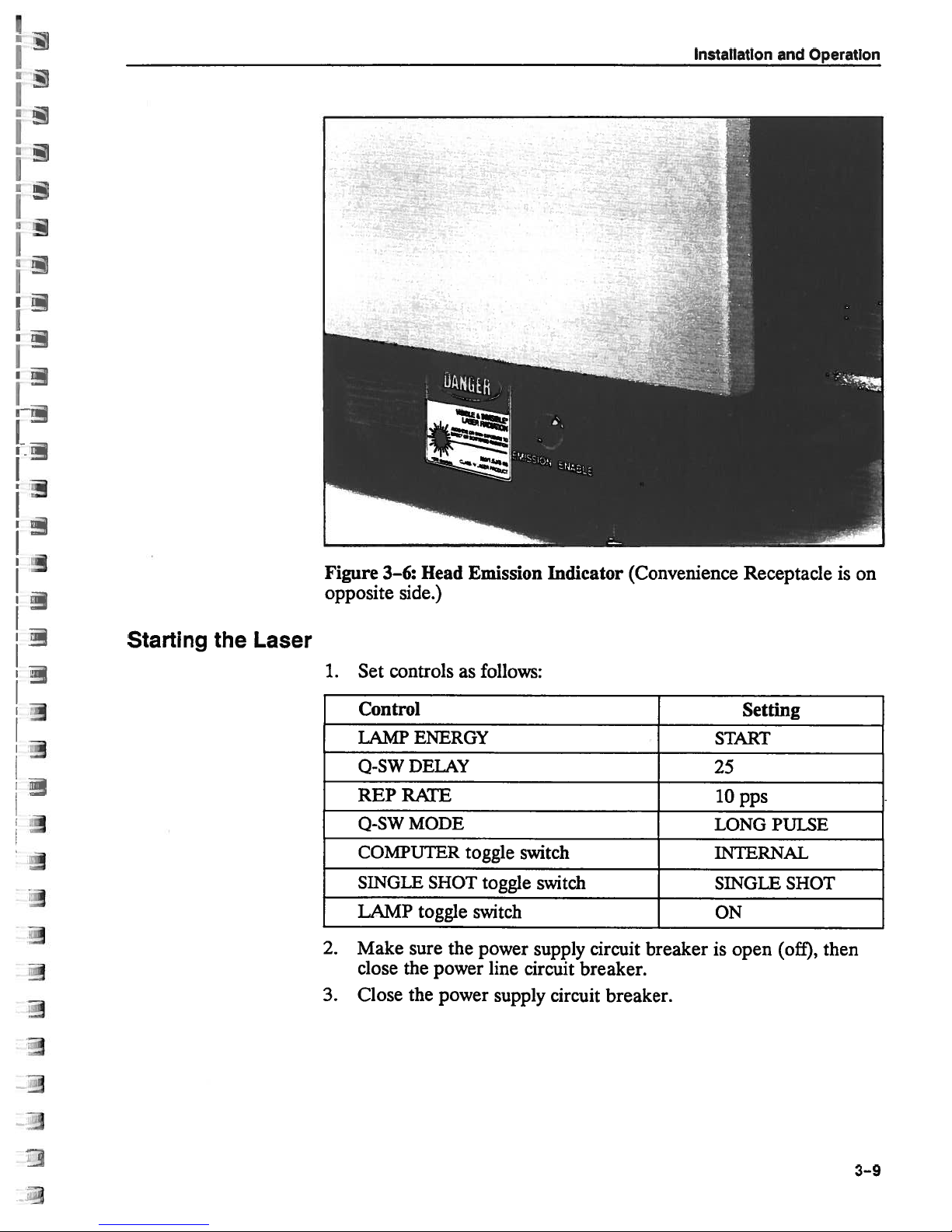
Installation
and
Operation
Starting
the
Laser
Figure
opposite
1.
Set
Control
LAMP
Q-SW
REPRATE
Q-SW
COMPUTER
SINGLE
LAMP
2.
Make
close
3.
Close
Head
3—6:
side.)
controls
ENERGY
DELAY
MODE
toggle
sure
the
the
as follows:
toggle
SHOT
the
power
power
Emission
switch
toggle
switch
power
line
supply
Indicator
(Convenience
START
25
lOpps
LONG
INTERNAL
switch SINGLE
ON
supply
circuit
breaker.
circuit
circuit
breaker.
breaker
is
open
Receptacle
Setting
PULSE
SHOT
(off),
is
then
on
3—9

Quanta—Ray
GCR
Series
NOTE
Low
tective
switching
the
Press
4.
Switchonthe
5.
about
Raise
6.
7.
Obtain
Polaroid
and
Avoid
the
If
8.
cavity
Q-SW
the
symmetrical,
mum
10
to
level
line
voltage
circuitry
power
power
the
ON
10
mm.
the
LAMP
burn
a
film
the
press
looking
burn
alignment.
MODE
SINGLE
increase
and
or
pps
desired.
or
in
supply
supply
circuit
button.
pump
air
operation
ENERGY
pattern.
in
the
SINGLE
the
at
pattern
If
to
Q-SW.
SHOT
you
switchitto
momentary
a
laser.
the
will
breaker,
and
to
Placeapiece
beam
SHOT
DANGER
film
is
asymmetrical
burn
the
Obtain
FIRE
can
the
button
safely
repetition
VARIABLE
If
glow.
set
purge
to
path
when
pattern
line
this
To
then
the
the
position
about
FIRE
taking
another
once.
raise
rate,
dropout
happens,
restore
close
flow
rate
cavity
7
on
of
unexposed
m
1
button
a
or
has
is
symmetrical,
burn
If
the
LAMP
the
i.e.,
and
will
an
operation,
it
again.
to
before
the
the
from
once.
pattern.
burn
flared
pattern
burn
ENERGY
switch
increase
trigger
LED
scf/h;
0.25
proceeding.
dial.
but
output
edges,
switch
pattern
the
the
pro
the
on
open
allow
developed
coupler
check
the
by
pressing
remains
maxi
to
RATE
REP
rate
to
p
the
the
allow
Only
adjust
permanently
can
covered
the
alignment
by
those
trained
damage
warranty.
WARNING
and
your
of
cavity
authorized
GCR
series
optics,
Spectra-Physics
by
laser.
and
Misalignment
such
damage
is
to
not
3-10

Chapter
4
Computer
Interface
Module
(CIM-1)
Functional
Overview
The
OCR
troller
log/TTL
(CIM-1)
or
remote
connected,
the
system
switch
With
RS-232-C
General
for
each
ports
right
The
OCR
controller
attached
COMPUTER
ON/ENABLE
computer.
this
mode
located
the
are
of
and
and
the
in
offers
Purpose
is
laser
COMPUTER
interface.
computer
is
to
key
CIM4
or
described
located
can
attached.
requires
Because
provides
a
system
The
standard
two
active
operate
switch
the
parallel
Interface
on
REMOTE
be
controlled
someone
switch
pushbutton
someone
an
remote
comes
interface,
optional
or
terminal
no
matter
with
must
GCR
IEEE
in
detail
the
control
connector.
Using
must
be
pressed
extra
area.
standard
interfaces
if
the
CIM-1,
be
on.
can
be
488
interface
Bus
in
by
the
system
to
manually
set
is
required
measure
with
the
latter
Computer
to
source.
computer
the
both
operated
or
OPIB).
chapter.
this
panel
computer
to
of
with
COMPUTER
in
order
of
Interface
connect
The
the
from
(the
Setup
the
with
the
enable
to
manually
to
safety
both
a
REMOTE
being
remote
latter
power
transfer
a
the
interface
OCR
either
also
and
Connectors
or
without
remote
the
system.
and
when
con
proprietary
Module
laser
to
a
controller,
is
used.
circuit
programming
supply,
the
control
start
the
breaker
serial
a
known
for
both
to
the
remote
controller
The
to
the
system,
computer
as
the
ana
local
if
For
the
INT/
the
is
Disconnecting
computer,
local
connected
including
operator.
in
the
This
place
remote
automatic
mode
of
the
controller
turn
of
operation
remote
transfers
on,
without
requires
controller.
control
intervention
a
jumper
entirely
plug
to
by
to
the
a
be
4-1

Quanta-Ray
GCR
I
Series
CIM-
The
IEEE
the
switches
one
common
choice,
The
dard
or
interface
set
CIM-1
interface
proprietary
located
is
REMOTE
and
gram
CIM-1
Power
computer
1
parallel
488
jumpers
can
both.
to
parameters
the
module
pc
interface
behind
interface
the
use
Low
Supply
interface
and
used
used
be
Simply
comprises
board
board
pc
front
the
connectors.
CIM-1.
Voltage
RS-232-C
select
to
at
a
connect
that
for
three
bottom
(the
(the
panel,
module
serial
one
time;
CIM-1
Interface
each
the
interface,
components:
pc
top
the
to
chapter
This
contains
interfaces.
the
or
controls
computer
board,
board).
pc
right
Standard
Board
separate
other.
OCR
the
to
use
and
power
Figure
The
COMPUTER
the
of
describes
inputs
hardware
interface
it.
supply,
and
CIM-1
how
are
to
There
However,
4-1),
for
no
only
of
stan
the
module
and
pro
I
I
I
RS-232-C
Interface
Figure
IEEE
Interface
4—1:
488
Location
of
CIM-1
PC
Boards
CIM-1
Interface
Proprietary
Board
4-2

Computer
Interface
Module
Computer
Control
Diagnostic
and
following
The
computer
Control
Laser
•
External
•
Variable
•
10
•
Q-switch
•
Long
•
External
•
Single
•
Single
•
Analog
•
Lamp
•
Lamp
•
Computer
•
Computer
•
Q-switch
•
Pulse
•
Rep
•
Q-switch
•
control:
Functions
on/off
lamp
rep
enable
pps
pulse
shot/rep
shot
strobe
blank
fire
forming
rate
Functions
control
fire
rate
enable
fire
enable
Q-switch
rate
fire
interlock
interlock
delay
network
set
advance
and
enable
enable
fire
select
clock
enable
sync
diagnostic
enable
(PFN)
functions
voltage
set
are
available
under
Power-On
Default
Diagnostic
•
•
•
•
State
When
prevent
PFN
Simmer
System
Computer
System
and
the
can
ware
the
must
voltage)
same
mands
initializes
GURE”
Secondly,
(PFN
is
START.)
Functions
voltage
voltage
interlock
system
occurrence
the
configure
be
CIM-1
the
provides
command
the
setting
as
monitor
monitor
monitor
first
of
control
and
before
module
a
the
monitor
turned
interlock
Initialization
is
used
information
zero,
to
on,
random
the
system
the
itself.
about
2,0
SET
pre-requisite
remote
must
control’s
C1M-1
the
events
system.
will
“CIM-1
routine.
this
be
for
interface
before
Commands:
used
operating
Lamp
the
initializing
Two
operate.
to
Energy
controlling
The
the
set
the
disabled
is
com
first
CONFI
lamp
GCR.
control
to
soft
energy
(This
to
4-3

Quanta—Ray
GCR
Series
Computer
IEEE
Operation
488
Safety
Interface
(Watchdog)
The
GCR.Ifa
shuts
Commands:
The
488-1978
I/O
32
talkers,
Talkers
the
to
Conversely,
and send
verters
CIM-1
the
controller
IEEE
Command
terminated
488
interfaces,
terminate
Interlock
CIM-1
down
IEEE
and
devices
listeners,
are
controller,
signals
(DACs).
is
just
488
can
detect a
failure
the
488
input
bus.
strings
by
messagestoit
occurs,
This
laser.
WRiTE
interface
comprises
listeners
suchadevice.
a
the
7,
that
are
or
talker-listeners.
devices
digital
e.g.,
are
fromitto
Talker-listeners
will
execute
sent
comma
CIM-1
communication
CIM-1
the
feature
for
n”
from
information
conformstothe
user-supplied
a
defined
that
voltmeters.
output
the
When
data
the
or line
(,)
does
(refer
opens
can
addressed
and
only
can
devices
real
world,
operate
the
transfers
controller to
feed
require
not
“Message
to
failure
the
disabled.
be
on
ANSI/IEEE
bus
monitor
They
that
e.g.,
in
both
C1M-1
to
(<LF>).
the
between
interlock
initializing
controller
by
events
“talk”
“listen”tothe controller
digitaltoanalog
directions.
is
properly
and
the
END
Formats”
itself
circuit
Refer
the
from it
CIM-1
to
this
standard
and
controller
and send
to the
programmed,
need
Unlike
command to
below).
“C]M-1
controller.
via
some IEEE
the
and
and
function.
from
The
the
to
1
as
data
con
be
to
Remote
Reset
Nevertheless,
END
The
sendingiteitheraDevice
for
command,
CIM-1
(SDC)
“Power-On
bus
details.
After
CIM-1
must
will
requireadelay
command.
receivingaDCL
not
conform
to
the
can
be
message,
Default
takes
about
send
CIM-1
reset
or
Inter
State”
0.5
messages to
with
controllers
sends
the power-on
to
CLear
above
sec
routine
ittoterminate
Face
andtoyour
NOTE
or
SDC
reinitialize.
to
the
programmed
default
or
(DCL)
Clear
command,
CIM-1during
immediately
Select
(IFC)
controller’s
Therefore,
to
all
data
state
Device
bus
reset.
or
TFC
the
this time.
following
recognize
transfers.
any
time
Clear
Refer
user
signal,
controller
Programs
any
the
by
to
manual
the
reset
4-4

Computer
Interface
Module
Serial
Poll
Status
Byte
The
sage
the
firmware
to
all
CIM-1
returning
by
command
last
(used
composition
facilitate
488
IEEE
Most
Significant
Bit
7
0
Figure
6
0
4—2:
responds
status
a
received,
factory
for
status
the
of
error
masking
controllers.
5
I
Firmware
Diagram
to
of
the
4
IEEE
byte
and
diagnostic
byte.
and
I
Version
serial
the
Serial
488
indicating
the
(b)
purposes).
This
status
recovery.
3
Command
poll
(a)
version
byte
This
2
Error
status
Poll
the
feature
byte.
Enable
execution
number
Figure
provided
is
is
1
Data
Ready
(SPE)
status
of
the
CIM-1
4-2
shows
primarily
standard
Least
Significant
0
Operation
Complete
mes
of
the
on
Bit
is
Bit
reset
Bit
command,
is
controller.
Bit
CIM-1
Bits
number.
Bits
The
ing
sending
set
0
(0)
is
set
1
when
reset
2isset
has
4,
3,
and
6
IEEE
an
SPE
Each
querying
IEEE
statements
(1)
during
when
and
when
aborted
and
Bit
5
7
are
488
command.
back
IEEE
488
when
the
5
is
controller
the
the
controller
the
the
execution
CIM-1
the
response data
CIM-1
error
an
the
indicate
the
most
always
The
status
488
controller
device
input
be
to
used.
CIM-1
has
command.
the
zero.
performs
byte.
hardware
finishes
of
has
ready
is
finished
is
detected
firmware
significant
CIM-1
NOTE
manufacturer
for the
a
command.
finished
for
sending
in
version
bit.
a serial
will
serial
manual
executing
executing
output
command
the
poll
automatically
status
for
to
the
as
a
of
the
has
byte.
samples
a
response
three-bit
command.
the
SAMPLE
controller.
the
line,
CIM-1byexecut
respond
own
its
Refer
of
It
to
the
and
binary
by
way
your
to
BASIC
the
is
It
of
4-5

Quanta-Ray
GCR
Series
SW2
DIP
Switch
Setting
followingisa
The
GPIB
Print
CIM-1
SPE
fertoyour
information
Input
CIM-1
one
The
SIC
The
selectadevice
attachedtothe
board
Controller
?rnt
#1,
Input
#2,
BASIC
is
a
has
command
BASIC
is
a
has
controller
requested
variable
CIM-1
sets
been
IEEE
and
been
IEEE
the
BASIC
Card:
“SPOLE’
A$
output
designated
that
causes
488
controller
command
input
designated
cardislikely
status
‘A$.”
address
address
byte
488
hardware interfaceiseasy
same bus.
statement
statement.
device
controller
its
language.
statement.
device
to be
is
read
is
that
from
different from
Dll
0
to
The
#1
manual
The
#2
used
into the
switch
31.
used
for
for
SW2
The factory
the
by
controller
output.
requestastatus
to
for
specific
controller
input,
for
both
IEEE
that
on
JO-Tech
attached
“SPOLE’isthe
attached
even
input
488
configure.
to
of
the
standard
setting
Personal
I/O
device
though
and
controller
all
other
is
the
to
byte.
setup
the
to
only
output.
as
Simply
devices
interface
25.
488
Re
BA
RS-232-C
Operation
Serial
Table
4—1:
Switch
Weight
Bit
Factory
Interface
RS-232-C
The
Data
Terminal
ment
(DCE).
25
pin,
D-sub
lines.
trol
signals
these
have
provided
that
anty
hardware
the requirements
Number
Setting
interface
The
type,
However,
and,
any
two
and
data
SW2
Device
Equipment
incompatible
DIP
Address
(25)
standard
and defines
unfortunately,
devices
format
of
standard
the
the
On
standard
will
mating
Switch
1
16
(16)
(DTE)
further
definitions.
settings
Settings
2
8
On
(8)
classifies
or
Data
identifiesaserial
its25pinsasvarious
does
not
manufacturers of
communicate
have
been
device.
for
Selecting
3
4
4
2
Off Off On
serial
As
I/O
devices
Communications
connector
data
narrowly define each
result
a
with
each
configured
serial
I/O
there
other
and
is
to
either
as
Equip
as
con
devices
no
guar
until
match
5
1
(1)
a
of
all
4-6
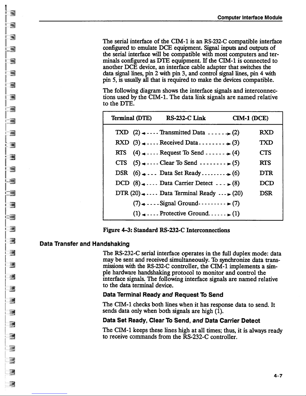
Computer
Interface
Module
The
serial
configured
the
serial
minals
another
data
pin5,is
The
tions
to
configured
DCE
signal
usually
following
used
the
DTE.
Terminal
TXD
RXD
RTS
CTS
DSR
DCD
interface
emulate
to
interface
will
as
of
DCE
DTh
device,aninterface
lines,
pin2with
all
thatisrequired
diagram
the
by
CIM-1.
(DTE)
(2)
(3)
(4)
(5)
(6)
(8)
.--
.
*
..,
..
-
--- -
-
- -
-
-
-
-
-
-
-.
-
-
-
-
Transmitted
Received
Request
Clear
Data
Data
the
CIM-1
equipment.
be
compatible
equipment.Ifthe
pin3,and
shows
the interface
The
data
RS-232-C
Data
To
Send
To
Set
Ready
Carrier
an
is
cable
make
to
link
Link
Data
Send
Detect
RS-232-C
Signal
with
most
adapter
control
the
signals
signals
- -
compatible
inputs
computers
CIM-1
that
signal
lines,
devices
and
are
CIM-1 (DCE)
(2)
a
(3)
.
(4)
.
(5)
(6)
a
(8)
a
and
outputs
is
connected
switches
pin4with
compatible.
interconnec
named
interface
of
and
ter
the
relative
RXD
TXD
CTS
RTS
DTR
DCD
to
Data
Transfer
and
Handshaking
DTR
Figure
The
4—3:
RS-232-C
maybesent
missions
ple
interface
to
the
Data
The
sends
Data
The
to
receive
with
hardware
signals.
data
Terminal
CIM-1
data
Set
CIM-l.
(20)
(7)
(1)
-
.
---
-
Standard
serial
and received
RS-232-C
the
handshaking
The
terminal
Ready
checks
only
when
Ready,
keeps
Clear
these
commands
- - -
Data
-
Signal
-
-.
Protective
RS-232-C
interface
following
device.
both
both
from
Terminal
Ground
GrouncL
Interconnections
operates
simultaneously.
controller,
protocol
interface
and
Request
lines when
signals
To
Send,
lines
highatall
the
RS-232-C
to
it
are
and
Ready
in
the
CIM-1
monitor
signals
To
Send
has
response
high
Data
times;
controller.
-
,
,..
the
full
To
synchronize
and
(1).
Carrier
thus,
(20)
(7)
(1)
duplex
mode:
implements
control
are
named
data
to
Detect
it
is
always
DSR
data
the
relative
send.
trans
a
data
sim
It
ready
4-7
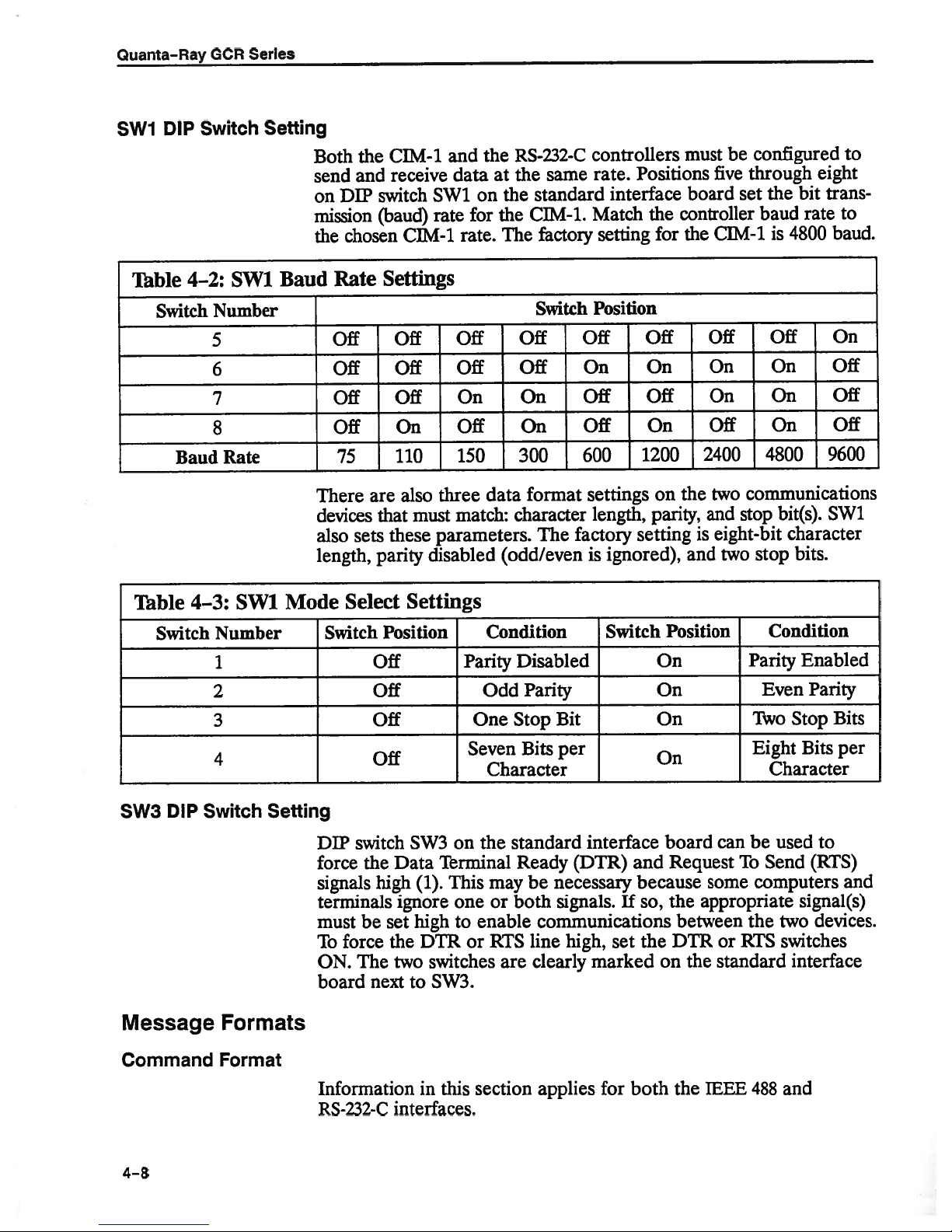
Quanta-Ray
GCR
Series
SW1
Table
DIP
4—2:
Switch
Baud
Switch
SW1
Number
5
6
7
8
Rate
Setting
Baud
Both
and
send
on
DIP
mission
chosen
the
Rate
Off
Off
Off
Off
75
There
devices
also
sets
length,
the
switch
(baud)
are
that
parity
CIM4
receive
(DIM-i
Settings
Off
Off
Off
On
110
also
must
these
disabled
the
and
at
data
the
on
SW1
for
rate.
Off
Off
On
Off
150
data
match:
the
The
(odd/even
rate
three
parameters.
RS-232-C
same
the
standard
C]M-1.
factory
Switch
Off
Off
On
On
300
format
character
The
factory
controllers
Positions
rate.
interface
Match
setting
Position
Off
On
Off
Off
600
settings
length,
is
1200
setting
ignored),
the
for
Off
On
Off
On
on
parity,
be
must
five
board
controller
the
the
and
CIM-i
Off
On
On
Off
2400
two
and
eight-bit
is
two
set
configured
through
the
baud
4800
is
Off
On
On
On
4800
communications
bit(s).
stop
character
bits.
stop
bit
rate
to
eight
trans
to
baud.
On
Off
Off
Off
9600
SW1
Table
Switch
DIP
5W3
Message
4—3:
SW1_Mode_Select_Settings
Number
1
2
3
4
Switch
Setting
Switch
Off
Off
Off
Off
DIP
switch
force
the
signals
terminals
must
be
force
To
ON.
The
board
next
high
Formats
Position
SW3
Data
(1).
ignore
high
set
DTR
the
switches
two
to
SW3.
Condition
Parity
Odd
One
Seven
Character
the
on
Terminal
may
This
or
one
enable
to
or
RTS
Disabled
Parity
Bit
Stop
per
Bits
standard
Ready
both
are
(DTR)
necessary
be
signals.
communications
high,
line
clearly
Switch
interface
and
because
If
so,
the
set
marked
Position
On
On
On
On
board
Request
the
between
DTR
the
on
Condition
Parity
Even
Two
Eight
Character
can
be
Send
To
some
computers
appropriate
the
or
RTS
standard
Enabled
Parity
Stop
Bits
used
to
(RTS)
signal(s)
devices.
two
switches
interface
Bits
per
and
Command
4-8
Format
Information
RS-232-C
in
this
interfaces.
section
applies
for
both
the
IEEE
488
and
commandisa
A
the
to
CIM-1.
three
forms:
to
up
lowing
string
A
command
additional
ASCII
of
consistsofa
or
data
characters
keyword
Computer
that
single
elements
Interface
the
computer
command
using
word and
one
of
Module
sends
the
fol
<command
<commandword>
<command
<commandword>
For
each
command
keyword
or
Command
meaning
words
to the
purposes.
A
command
elements
(<LF>)
cally
<LF>
command
Command
case
<LF>,
preted
Examples
and
characters
the
commaisused
used
word
words
alpha
characters.
are ignored
as
a
word>
word>
elements
and
CIM-1
includes
terminate
terminate
to
and the
and
single
<LF>
<data>
<data>,
<data>,
word,
the
following
CIM-1
keywords
and
can
delimiter
each
command.
are
keywords
Spaces
by
delimiter, and
interchangeably
used
between
the
element(s)
and
the
CIM-1.Consecutive
<LF>
<data>
<keyword>,
expectstofind
it.
Dataisalways
are
reserved
onlybeused
characters
that
The comma
elements
command. The
following
contain
may
all
all
but
ofacommand
nonprintable
the
<LF>
<keyword>
appropriate
in
integer
that
words
for
narrowly
separate
for
this
delimiter
may
be
either
delimiters
firstisignored.
have
command
and line
(,)
purpose.
between
omitted.
upper
characters,
<LF>
form.
unique
defined
Typi
with
or
lower
except
inter
are
data
feed
the
Response
Format
SET
WRITE4,1001B,
Sample3<IF>
Command
they
must
or
out
be
aborted.
An
input
spelled
incorrect
is
detected,
next
command.
set
(1)
After
data
to
<response>
The
CIM-1
the
IEEE
127
1,
words
includeatleast
abbreviated,
error
command
number
the
(refer
executing a
the
computer
also
488
<LF>
WRITES,
and
keywords
the
commands
occursifany
word
or
keyword,adata
of
elements
CIM-1
Bit2of
to
“IEEE
sends
interface
aborts
the
488
Interface:
SAMPLE command,
followed
<CR>
the
is
<LF>
END
used.
O11OB
may
first
three
must
part
ofacommandisinvalid,
in
the
command
IEEE
488
byacarriage
message
<LF>
be
abbreviated
characters.
be
spelled
value
command.
processing and
interface
Serial
the
Poll
CIM-1
return
to
terminate
(Figure
Whether
correctlyorthey
out
of
When
status
Status
an
byte
Byte”).
sends
and
4—4),
spelled
e.g.,
range,
input
waits
register
requested
the
line
feed:
transmission
or
for
but
will
mis
a
an
error
the
is
if
4-9
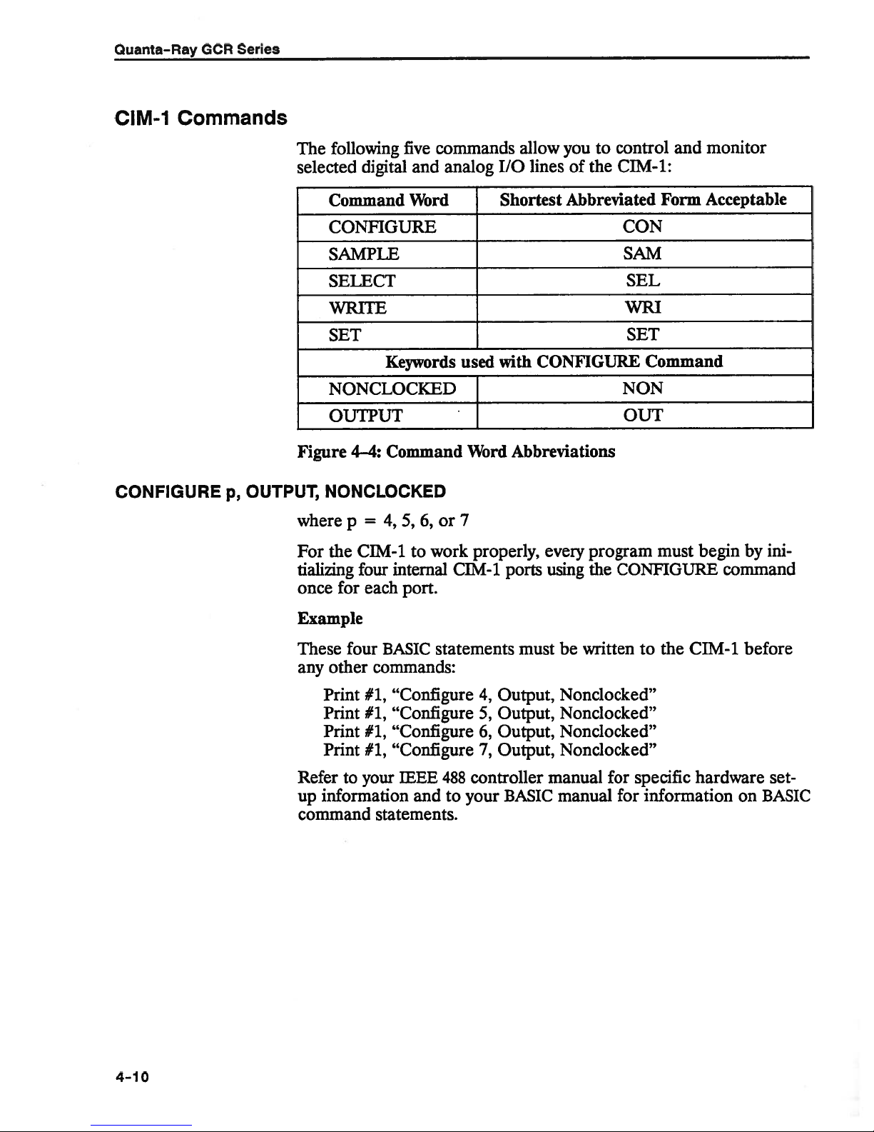
Quanta-Ray
GCR
Series
CIM-1
Commands
CONFIGURE
OUTPUT,
p,
following
The
selected
digital
Command
CONFIGURE
SAMPLE
SELECT
UTE
SET
NONCLOCKED
OUTPUT
Figure
4—4:
NONCLOCKED
where
=
p
five
commands
and
Word
Keywords
Command
5,
6,
or
4,
analog
used
Word
7
you
allow
I/O
Shortest
with
Abbreviations
of
lines
Abbreviated
CONFIGURE
to
the
control
CIM-1:
CON
SAM
SEL
WRI
SET
Command
NON
OUT
and
Form
monitor
Acceptable
the
For
tializing
for
once
Example
These
any
four
other
Print
Print
Print
Print
Refer
up
to
information
command
CIM-1
four
each
to
internal
port.
BASIC
work
CIM-1
statements
commands:
#1,
“Configure
#1,
“Configure5,Output,
#1,
“Configure
#1,
“Configure7,Output,
IEEE
your
and
488
to
your
controller
statements.
properly,
ports
must
4,
Output,
6,
Output,
BASIC
program
every
be
the
written
using
Nonclocked”
Nonclocked”
Nonclocked”
Nonclocked”
manual
for
manual
must
begin
CONFIGURE
the
to
specific
for
information
CIM-1
hardware
ini
by
command
before
set
on
BASIC
4-10

Computer
Interface
Module
SAMPLE
SELECT
WRITE
p,
a
where
This
Table
a
1
2
3
4
c
where
The
etaiy
major
Tables
n
where
The
that
major
4—5
is
represented
require
no
=
1to4
a
command directs
4-4:
SAMPLE
Monitor
PFN
Function
Voltage
•
Simmer
Interlock
Computer
Interlock
or
c=1
CIM-1
interface
groups
4—5
=
p
n
=
2
multiplexes
board.
to
be
and
4—6
4,
5,
four-bit
a
equivalent from
WRiTE
belong
groups
and
to
4—6.
command
oneoffour
selected
The
as
four
digits
suffix.
CIM-1
the
Command Functions
a
Data
Data
Data
Data
Data
Data
Data
Data
two
major
The
SELECT
addressed
forafunctional
6,or7,
and
binary
sets
and
sub-groups
using
four-bit
either
followed
number
a
binary
by
to
sample
Value
=
1
=
200
>
200
<
200
>
200
<
200
>
200
<
200
groupsofI/O
command
by
the WRiTE
listingofthe
number
to
0
resets
(0000b
15
four
(p)
the SELECT
used
or
decimal
the
suffixb;decimal
the
following:
Interpretation
from
0
to
10VPFN
1800
SimmerisON
Simmer
Interlock
All
interlocks
Computer
fault
Computer
closed
ports
singles
command.
two
to
hub)
control
that
make
command.
with
the
WRITE
number.
254
Voltage
V
PFN
Voltage
is
OFF
fault
closed
interlock
interlock
on
the
propri
out
one
of
(Refer
to
groups.)
oradecimal
lines
atatime
up
one
of
two
Refer
to
Tables
command
Binary
numbers
numbers require
two
(n)
Examples
WRITE
WRITE
Some
functions
mutually
required
control
Sequence
for
details
4,
4,
exclusive.
perform
to
functions.
Timing,”
and
on
operation
ilOOb
12
require
Often
a
Refer
or
other
twoorthree
single
to
and
and
operation
Chapter
Chapter
control.
functions
1,
3,
to be
WRITE
because
preset,
commands
of
the
“Introduction:
“Installation and
while
others
will
interaction
Pulse
Triggering
Operation,”
are
be
of
4-11

Quanta-Ray
GCR
Series
Table
4-5:
SELECT
Command
4,
WRITE
WRiTE5,xxxlb
WRITE
xxxlb
mOb
xxlxb
xxOxb
xlxxb
x0xxb
lxxxb
0mb
xxx0b
xxlxb
xx0xb
xlxxb
x0xxb
Oxxxb
xxxlb
6,
xxx0b
xxlxb
xx0xb
xlxxb
x0xxb
lxxxb
1mb
Oxxxb
WRITE
1,
Turn
system
Turn
system
External
External
Variable
Variable
lOpps
lOpps
Internal
Internal
Long
pulse
Long
pulse
External
External
System
System
Single
Single
after
each
Analog
Analog
Lamp
Lamp
Lamp
Lamp
Command
on
off
lamp
lamp
rate
rep
rep
rate
rep
rate
rep
rate
Q-switch
Q-switch
enabled
disabled
Q-switch
Q-switch
for
set
for
set
shot
trigger
trigger
shot
shot)
strobe
strobe
blank
blank
trigger
and
enabled
disabled
pulsed
Q-switch
Function
enabled
fire
fire
disabled
enabled
disabled
enabled
disabled
trigger
trigger
fire
fire
repetitive
single
pulsed
reset
read
latch
(last
trigger
Functions
enabled
disabled
enabled
disabled
firing
shot
(must
(lamp
be
value
cannot
reset
reset
latched)
fire)
4-12
WRITE
7,
xxxlb
xxx0b
xxlxb
xxOxb
Computer
high
transition)
Reset
from
pulse
WRITE
Computer
Computer
interlock
(hightolow
xxxlb
7,
watchdog
watchdog
clock
reset
transition)
interlock
interlock
(low
enabled
disabled
to

Computer
Interface
Module
SELECT
SELECT
1,
WRITE
1,
WRITE5,n
4,
Table
WRITE4,n
WRITE5,n
WRITE6,n Sets
WRITE7,n Sets
n
Turns
4-6:
Command
system
operation:
than
more
lamp
lights
the
erroriscleared
Selects
the
longpulse,and
orinsingle
Q-SW
the
command sequence.
MODE
OCRisdisabled until
SELECT
Sets
(—700
Sets
(0.1
power
external
one
on
lamp
the
onoroff
lamp
trigger
remote
by
configuration
also
determines
shots.Ifmore
ERROR
2,
WRITE
the
lower four
to+400 nsec)
upper
the
the
lower
15.0
to
the
fire,
pps)
upper
and
variable
source
control
writing
of
than
lamp on
the
correct
a
the
Q-switch:
whether
one
the
erroriscleared
Command
four
four
four
selects
rep
is
selected,
box,
Q-switch
remote
Function
bits
for
bits
for
bits
for
bits
for
oneofthree
rate,
and
the
and
the
command
internal
OCR
the
modeisselected,
control box
by
Functions
Q-switch
Q-switch
lamp
lamp
SOURCE
OCRisdisabled
or
will
writing
advance
advance
repetition rate
repetition rate
modesoflamp
10
sequence.
fixed.
pps
external
fire
repetitively
will
a
ERROR
trigger,
light,
correct
sync
sync
If
until
or
the
and
SELECT
1, WRITE
SELECT1,WRITE
6,
n
Controls
Lamp
going pulse;
trigger,
inhibit
high
low
set
rep
7,
n
Controls
to
1.
2.
lamp
trigger
logic
logic
points
rate,
enable
The
between
on
for eachofthe
The
and
therefore,
then reset
function.
level
level
for
controlling
and
PFN
the
computer
the
computer
watchdog
1
the
proprietary
computer
trigger,
Q-switch
to
Analog
causes
latches
voltage
interlock
and
255
switches
interlock
lamp
blank,
trigger
the corresponding
get
ready
strobe
the
set
the
last
Q-switch
analog
both
for
the
isasample-and-hold
point
analog reading.
advance
monitor.
interlock
watchdog
sec
interface
system.
interval
via
the
board
are
marked
enable
interlock:
watchdog
line
strobe,
and
single-shot
requireaprogrammed
bit
must
be
toggled
next
to
pulse.
follow
Lamp
the
analog
Itisused
function
sync, Q-switch
Three
timer
(Figure
must
conditions
must be
timer DIP
on
the
be
preset
4—5).
pc
board.
high.
The
trigger.
positive-
high
blank
to
delay,
are
toavalue
switch
input
set
bit
is
where
variable
required
SW1
weights
to
an
and
a
analog
a
4—
13
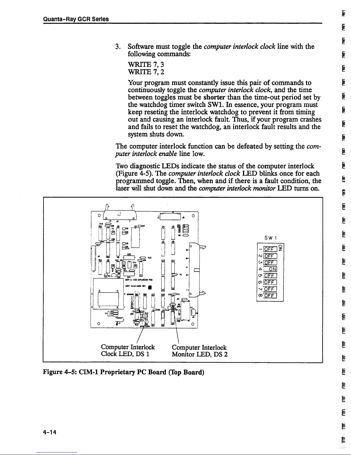
Quanta-Ray
GCR
Series
3.
Software
following
must
toggle
commands:
the
computer
interlock
clock
line with
the
WRITE
WRITE
Your
continuously
between
the
keep
out
and
system
The
puter
Two
(Figure
programmed
laser
r
1
ua
7,
3
7,2
program
watchdog
reseting
and
causing
failstoreset
shuts
must constantly
toggle
toggles
must
timer
the
an
down.
the
be
switch
interlock
interlock
the
watchdog,
computer
shorter
computer interlock function
interlock
diagnostic
4-5).
will
shut
enable
LEDs
The
computer
toggle.
down
air
line
low.
indicate the status
interlock
Then,
and
_.a
when
computer
the
0
issue
this
pair
interlock
the
than
SW1.Inessence,
watchdog
to
preventitfrom
fault. Thus,ifyour
an
interlock
can
be
clock
defeated
of
the
LED
andifthereisa
interlock
of
commands
clock,
and
the
time-out period
your
program
program
fault
results and the
setting
by
computer
blinks
fault
monitor
interlock
once
condition,
LED
to
time
set
must
timing
crashes
the
each
for
turns
by
fr
com
the
on.
Figure
4—5:
•
CIM-1
LJLj
N.
P;Z
H
9
,02
sauna
Computer
Clock
Proprietary
c2
3
XR11
?.SSY
a
LED,
I
RIG
EXPAISIOGI
Un
Pta
D44UtUO
V
C
/
Interlock
DS
1
PC
Board
pta
Computer
Monitor
(Top
LED,
Board)
Interlock
DS
SW
1
IO1
-
R)
CaP
OFF
-
ONI
()‘OFF
c[OFF
•-JOFF_I
°QEEJ
I
I
2
4-14
SETd,n
where
or
The
SET
0-switch
To
set
=
d
=
d
command
delay
0-switch
the
Computer
the
set
0to250
n
n
used
the
=
0
set
to
PFN
the range
in
to
and
1
and
2
is
and
time
delay
(to
200
(to
analog
voltage.
60
the
set
values
278
to
that
Interface
Q-switch
voltage)*
PFN
govern
p.sec:
Module
delay)
the
n
set
The
the
maximum
To
*
electronics
the
factoiy.
dangerous
damage
on
to
test
the
precision
If
to
sary
the
real
sampling
programmed
herent
voltage
PFN
the
grammed
INT
=
PFN
desired
=
the
on
This
energy
various
report
correct
sense
PFN
offset
is
less
voltage
(delaY)+318)
(—--
in
voltage
10
PFN
CIM-1.
feature
levels
optical
accompaning
is
required
for
voltage
voltage
value
of
the
than
value
the
voltage
voltage
Each
prevents
the
in
components.
inherent
an
monitor,
of
PFN
system.
measured
the
is
greater
to
used
for
at
range
ilamp
laser
the
laser
the
NOTE
setting
TP24
voltage
Either
than
set
0
energy
system
software
cavity,
laser
offset
on
and
the
the
PFN
1800
to
is
is
thereby
value
The
for
the
PFN
the
in
the
the
compare
The
set.
this
add
voltage)
measured
voltage.
V:
hardware
individually
program
avoiding
the
of
software
voltage,
electronics.
control
pe
this
difference
offset
or
subtract
voltage)
limited
adjusted
creating
from
potential
is
limit
provided
programmer
neces
it
is
Measure
board
value
to
(if
is
it
to
the
the
from
the
by
or
PFN
pro
the
at
by
the
in
(if
Examples
External
Variable
lamp
rep
fire
If
the
must
allowing
rate
If
(0.1
numbers.
where
external
command
variable
lamp
SELECT1,WRITE
SELECT
it
follow
to
15
rep
to
external
rate
rep
pps)
determine
To
is
rate
must
fire
is
1,
WRITE
disable
triggering.
is
selected,
be
0.1
to
selected:
4,
6,
lamp
written
that
number,
pps:
15
xxlxb
lOxxb
blank
an
8-bit
using
and
value
two,
first
to enable
equal
four-bit
the
find
lamp
to
the
binary
value
trigger,
rate
rep
decimal
or
for
count
thus
4-15

Quanta-Ray
GCR
Series
count
I
rep
=
255
rate
15
Next, find
m
Next,
find n,
n
n
Finally,
insert
statements:
SELECT
WRITE4,xlxxb
SELECT
WRITE6,n
WRITE7,m
Example
To
setarep
count
the
INT
integer
count
m,
=
16
the
integer
=
INT(count—(l6xm))
=
TNT
the
(count
MOD
values
1
2
rate
of12pps:
=
255
----
15
value
remainder
of
count
from
16)
fornandmin
=
204
divided
the
or
[BASIC
appropriate
the
[selects
lower4bits]
[sets
[sets
upper4bits]
by
16:
above
statement]
variable
division:
WRITE
rep
rate]
Q-switch
Advance
Pluginthe
Sync
Selecting
senting
numbers.
where
Next,
m=TNT
n=count
values
SELECT
WRITE
WRITE
Q-switch
the
value
To
determine
adv
sync
count
find
the
=
2
6,12
7,
chosen
is
a
=
—47+
integer
=12
16
(16xm)
formand
12
advance
to be
that
value
from
adv
m:
count
16
=
12
n:
also
sync
writtenintwo,
number,
—700
66656
sync
+
945
requires
first
find
to+400.
an
4-bit
the
8-bit
binary or
value
number
for
repre
decimal
count,
4-16
p

and
n,
the
n
n
integer
=
INT
=
INT
remainder
(count)
(count
16—
MOD
from
m))
16)
above:
or
[BASIC
Computer
statement]
Interface
Module
Finally,
insert
statements:
SELECT
WRITE
WRITE
Example
To
Q-switch
set
count
Next,
find
m=INT-
n
n=103—(16x6)
Plug
in
the
SELECT
WRITE
WRITE
the
=
values
the
=
values
count
4,
5,
values
2
(selects
n
4,
(sets
m
(sets
5,
advance
—47+
for
16
—
(16
for
m
2
7
6
for
andm
n
Q-switch
lower
sync
upper
for
4
bits)
4
bits)
—500
66656
—500+945
m
and
n:
=6
x
m)
or
=7
and
n:
in
the
advance
nsec:
=
103
appropriate
sync)
WRITE
Sample
Analog-to-Digital
Conversion
Actual
actual
the
PFN
PFN
SAMPLE
PFN
Example
If
then
PFN
Lamp
energy
following
Lamp
Example
If
Then
Lamp
voltage
voltage
1
command,
voltage
SAMPLE
PFN
voltage
can
equation:
energy
PFN
voltage
lamp
energy
is
four
(0to1800
=
SAMPLE
1
returns
voltage
=
1000
now
be
=
=
energy
=
times
V),
then
a
=
100
V
determined
0.000025
1000
V
=
0.000025
25.0
the
query
multiply
1
x
count
x
10
x
(PFN
sampled
PFN
by
10
of
100,
or
V
from
PFN
voltage)
2
10002
x
voltage.
voltage
10:
monitor
voltage
J
L
To
using
find
the
using
the
4—i
7

Quanta-Ray
Example
on
Example
OPEN
pB.II’T’#1,
PRINT#1,
PRINT#1,
PRINT#1,
PRINT#1,
PRINT#1,
PRINT#1,
PRINT#1,
PRINT#1,
PRINT#1,
PRINT#1,
PRINT#1,
Personal
a
1:
“COMi:
Series
GCR
Commands
Computer
RS—232
“CONFIGURE
“CON
“CON6,OU’l
“SELECT
“WRI
“WRI6,0,
“SELECT
“WRI
“WRI
“SEL
“WRI
set—up,
4800,N,8,2,”
5,
OUT,
1,”
4,0,WRI
WRI
2,”
WRI
4, 0,
WRI
6,
0,
WRI
1,
4,
0000B,”
laser
4,
NON,”
NON,
5,
7,
5,
7,
4,
0001B,”
Using
turnonand
RANDOM
FOR
OUTPU]
CON
0,”
0,”
0,”
0,”
Basic
GW
off
1
AS
NONCLOCKED”
NON,”
OU’I
7,
‘Initialize
‘Clear
CIM-1
‘Initialize
CIM-1
‘Open
‘Initialize
expansion
‘Open
‘Initialize
on
‘Turn
off
‘Thrn
COM1
RS-232
CIM-1
digital
CIM—1
expansion
power
power
as
input/output
ports
ports
digital
digital
ports
digital
ports
Example
PRINT#1,
PRINT#1,
PRINT#1,
Example
PRINT#1,
PRINT#1,
PRINT#1,
PRINT#1,
Example
PRINT#1,
PRINT#1,
PRINT#1,
PRINT#1,
PRINT#1,
PRINT#1,
PRINT#1,
PRJNT#1,
PRINT#1,
2:
Start
simmer
1,”
“SEL
“WRI
“SET
Q-switch
3:
“WRI
“WRI4,1001B,”
“WRI
“SET
4:
Q—switch
“WRI
“SET
“SET
“SELECT
“WRI
“WRI
“SELECT
“WRI
“WRI
OO1OB,”
6,
2,
0,”
off,
000DB,”
5,
OO1OB,”
6,
155,”
2,
on
OO1OB,”
6,
2,
155,”
204,”
1,
2,”
1,”
6,
1,”
7,
1001B,”
5,
O1O1B,”
4,
1,”
(assumes
lamps
with
100
at
power
10
jisec
is
Hz/60
delay.
on—see
(assumes
U
Lampsat1
Example
simmer
Hz/60
1)
‘Analog
‘Set
PFN
is
on)
‘Q-switch
‘Enable
‘Analog
PFN
‘Set
For6OU,PFNV
See
J
(assumes
‘Analog
lamp
‘Set
‘Set
Q—switch
‘Set
rep
rep rateto1
‘Set
‘Enable
read
V
to
0
disabled
10
Hz lamp
read
volts:
J
d,
“SET
simmer
read
U
60
to
delay
rate
to1pps
Q—switch
operation
=
0.000025
n”
for
is
to
pps
and
=
1549
algorithm
on)
100
isec
(lower
(upper
repetitive
4
4
—
bits)
bits)
V
2
firing
4-18

Computer
Interface
Module
Example5:Q—switch
PRINT#1,
PRINT#1,
PRINT#1,
Example
PRINT#1,
PRINT#1,
PRINT#1,
PRINT#1,
PRINT#1,
PRINT#1,
“WRI
“WRI
“WRI
Q—switch
6:
“WRI
“WRI
“WRI
“WRI
“WRI
“WRI
5,
6,
6,
6,
4,
5,
6,
6,
6,
single
(Assumes
as
0001B,”
0001B,”
000DB,”
single
(Assumes
001DB,”
OO11B,”
0001B,”
00018,”
1000B,”
0000B,”
shot
well
shot
lamps
at
some
a
preprogrammed
as
simmering
lamps
some
fixed
some
preprogrammed
PFN
rep
voltage
rate
rep
Q—switch
and
Q—switch
and
PFN
rate
and
delay
‘Enable
‘Send
‘Reset
‘Result:
from
predictable
‘Lamp
‘Enable
‘Enable
‘Thgger
‘Send
‘Thin
‘Result:
from
mode
Example
is
voltage
PFN
setting—see
Q-switch
single
a
single
0-switch
next
shot
single
delay
trigger
external
single
Q—switch
lamp
a
single
off
0—switch
lamp
characteristics
preferred.
voltage
shot
shot
lamp
is
set—see
and
shot
trigger
trigger
5
mode
and
trigger
will
mode
output
single
lamp
Single
shot
will
setting,
example
single
trigger
fire
trigger
of
operation
mode
example
fire
Q-switch
and
and
lamp
fire
pulse.
are
of
single
4)
shot
pulse
Q-switch
on
pulse.
characteristics.
4)
shot
off
shot
trigger
on
Q—switch
Note:
not
shot
mode
delay
Note:
This
produces
fire
delay
output
guaranteed.
operation
Example
PRINT#1,
PRINT#1,
PRINT#l,
External
7:
“SEL
“WRI
“WRI
Q-switch
1,”
5,
110DB,”
5,
000DB,”
fire
(Assumes
ator
is
panel.
The
panel
and
lamps
required
pulse
adjusted
at
10
to
inject
generator
for
Hz/60
a0to
a
pulse
3—see
5
triggered
is
width
V
signal
example
into
from
of
1
msec
‘Enable
Result:
‘Disable
Result:
this
sion
racy
2)
Setup:adelaying
the
the
and
external
external
method
required
is
of
Q—Sw
“Ext
“Lamp
appropriate
Q-switch
Q—switch
Q-switch
0—switch
is
useful
the
CIM-1.
Sync”
will
will
than
pulse
Trig”
BNC
BNC
0—switch
fire
fire
at
fire
stop
when
the
8-bit
gener
on
the
10
firing.
more
on
delay.
Hz
Note:
preci
DAC
the
rear
rear
accu
4-19

Quanta-Ray
GCR
Series
i’I
Example
CALL
IF
DELAY
LOC
PRINT#1,
CALL
DELAY
WHILE
WEND
SMMER$
iF
VAL
SIMMER$
ELSE
SIMMER$
IF
END
Example
PRINT#1,
PRINT#1,
PRINT#1,
TIMER
ON
TIMER
WHILE
WEND
END
Simmer
8:
SEC)
(1
THEN
0
<>
(1)
(1
(1)
INPUT$
=
2,”
SEC)
“SAM
EOF
(SIMMER$)
“OFF”
=
=
“ON”
Computer
9:
“SEL
1,”
“WRI
7,
“WRI
7,
(5)
GOSUB
ON
1
monitor
DUMMY$
(LOC(1),
<
100
Interlock
0000B,”
OO1OB,”
CLOCKPULSE
(on/off
THEN
(assumes
simmer
#1)
INPUT$
=
laser
status)
is
(LOC(1),
and
on
#1)
‘Read
‘Wait
‘Let
‘Simmer
‘Simmer
expansion
‘Open
‘Disable
‘Enable
‘Send
‘Enable
‘Endless
‘Clear
IJIB
ADC,
EOF
for
SIMMER$
=
off
=
on
PCB
DIP
digital
UIB
computer
computer
pulse
clock
event
loop
input
=
0
255
switch
ports
interlock,
eveiy
trap
buffer
input
A-1N2
string
data
set
is
interlock,
5
timer
sec
5
sec
to
clock
sec)
8
clock
I
off
off
CLOCKPULSE:
PRINT#1,
PRINT#1,
“WRI
“WRI
OO11B,”
7,
OO1OB,”
7,
‘Create
‘Clock
‘Clock
‘Result:
will
interlock
ser
computer
on
off
computer
blink
monitor
will
not
evexy
shut
pulse
clock
interlock
sec.
5
LED
off.
clock
Computer
is
always
LED
off.
La
4-20

Chapter
5
Installing
HG—2
WARNING
and
Operating
Harmonic
the
Generator
KD*P
peratures
them
ronment.
factory-trained
pink.
crystals
slowly.
wet
and
Check
are
sensitive
They
maintain
the
desiccant
service
to
are
also
a
low
engineer
thermal
water
relative
weekly
when
shock,
soluble,
humidity
and
have
it
turns
so
change
avoid
so
in
it
changed
from
their
tem
getting
envi
by
blue
a
to
Figure
5—1:
HG-2
Component
Identification
5—1

Quanta—Ray
GCR
Series
the
Find
the
on
wavelengths
put
prisms,
Table
Stage
1st
2nd
Table
Output
nm)
X
1064
532
355
266
combination
left-hand
equivalent
or
Summary
5—1:
Summary
5—2:
of
Interest
Polarization
Vertical
Vertical
Horizontal
Vertical
Horizontal
Vertical
Horizontal
Vertical
Horizontal
Vertical
Horizontal
Vertical
Horizontal
side
are
Arm
wavelength,
of
table.
the
of
collinear;
optics.
of
Position
0
I
II
0
T
F
of
SHG
polarization,
the
Set
be
can
they
Translation
EEG-2
Settings
Crystal
—
I
I
II
II
I
I
II
II
I
I
II
U
and
HG-2
as
separated
1st
Type
Type
2nd
Positions
stage
SHG
2
I
IT
stage
Arm
THG3crystal
FHG
4
Main
crystal
Housing
Position
—
Horizontal
Vertical
Horizontal
Vertical
Vertical
Horizontal
Vertical
Horizontal
Vertical
Horizontal
Vertical
Horizontal
SHG
described
dichroic
by
crystals
crystal
SHG
2
crystal
crystals
in
in
crystal
on
Crystal
out
out
beam
beam
HG-2
1st
Position
for
right-hand
the
beam
Position’
beam
of
beam
in
beam
in
of
path
path
Settings
1
Stage
0
I
I
II
II
I
I
II
II
I
I
II
II
the
splitters,
beam
output
path
path
path
path
interest
of
All
side.
dispersive
Stage
2nd
Position
0
0
0
0
0
T
T
T
T
F
F
F
F
I
out
with
HG-2
harmonic
Type
orientation
the
of
an
Generation
Generation
Generation
second
II
the
hannonic
produces
the
of
1.
2.
3.
4.
5.
5-2
describes
Table
Second
Third
Type
Fourth
fundamental.
Refers
polarization
Harmonic
Hannonic
second
I
Harmonic
to
a
full
complement
nm)
(532
nm)—occurs
(355
optimal
(266
nm)
harmonic
axis
of
are
output
by
harmonic
third
—occurs
produces
rotation
of
perpendicular
hannonic
of
summing
generating
by
optimal
first
the
to
generation
fundamental
the
performance.
the
second
harmonic
fourth
crystals.
stage
axis
this
of
crystals.
harmonic
performance.
Both
rotation.
(1064
first
the
nm)
of
stage
the
and
second
its
second
harmonic
translation
harmonic.
of
and
ann
the
the
Harmonic
Generator
HG-2
Controls
Input
beam
Crystal
and
out
crystals.
of
the
5—2).
Notches
Never
running.
Angle
of
the
aligning
Main
ization
desired
Polarization
align
to
Rotator—rotates
it
with
Translation
of
the
beam
The
first
stage
polarization
move
Tuning
crystal
it
for
with
in
the
the
Knob
the
the
of
arms
crystal
most
input
Housing—rotates
of
the
output.
orientation.
the
first
Arm
(one
path
and
crystal
the
output
lock
into
(one
for
efficient
beam.
about
Clamping
the
crystal.
stage
for
each
serves
as
translation
beam
the
(see
crystals
WARNING
out
or
each
of
tuning
harmonic
the
optical
screws
lock
polarization
stage)
a
the
lever
arm
note
in
beam
arm)
—slides
for
serves
five
position.
—adjusts
generation,
axistochange
the
polarization
angle
as
following
while
of
the
the
tuning
an
the
the
optically
the
input
crystals
the
indicator
Table
laser
is
angle
polar
in
the
in
Installing
the
HG-2
The
HG-2
following
crystals
1.
Remove
Install
2.
in
place.
Install
3.
spring-loaded
next
HG-2
4.
Place
with
mounting
ment
Slide
5.
moves
optically
was
procedure
in
the
unit.
wrapping,
the
L-frame
the
HG-2
screws
hold-down
to
a
vertically.
the
HG-2
corresponding
screws,
of
the
HG-2.
both
crystal
the
crystals
aligned
should
tie-downs,
extension
baseplate
hold
screw,
so
the
four
threaded
but
leave
translation
Out
of
be
the
optimal
on
it
work
the
at
and
on
the
factory,
restrainers
the
L-frame
down.
against
elongated
holes
them
loose
arms
to
beam
harmonic
OCR;
Three
setscrews,
the
holes
in
the
baseplate.
allow
to
the
“0”
path.
the
so
result
generation
from
two
cap
extension;
springs
its
on
yoke
horizontal
position,
HG-2.
the
screws
three
each
to
adjust
Start
which
of
the
from
hold
located
line
all
move
all
it
the
up
four
5—3

Quanta—Ray
GCR
Series
________________________________________________
6.
Start
the
laser,
then
set
its
controls
follows:
as
I
LAMP
Q-SW
REP
Q-SW
COMPUTER
SINGLE
LAMP
Adjust
7.
both
on
for
vation.
loaded
loosen
screw
Connect
8.
for
ENERGY
DELAY
RATE
MODE
toggle
the
input
the
If
screws
one
next
mm.
15
Control
toggle
SHOT
switch
HG-2
input
the
beam,
must
you
allow,
spring-loaded
Repeat
it.
to
purge
the
before
switch
output
and
move
“walk”
switch
reduce
the
screw
toggle
horizontally
and
with
system
proceeding.
and
beams.
HG-2
the
the
to
the
vertical
and
other
the
vertically
Use
ambient
vertically
adjustment.
tighten
vertical
harmonic
Setting
threshold
near
25
pps
10
LONG
]NERNAL
REPetitive
OFF
to
an
the
PULSE
center
JR
card
for
light
more
vertical
adjustments.
generator
windows
its
detector
a
as
easier
than
Simultaneously
obser
spring-
its
adjustment
purge
and
Operation
Turn
9.
an
the
and
Verify
1.
before
2.
Set
Never
running.
Example—to
crystal:
a.
places
b.
moves
on
card.
IR
beam.
check
the
proceeding.
crystal
the
move
Slide
the
Slide
the
laser
the
Adjust
Turn
the
again
flow
the
the
for
through
translation
the
crystal
obtain
first
TypeIcrystal
second
second
and
the
HG-2
clipping.
the
stage
stage
stage
check
baseplate
to
purge
the
arms
WARNING
or
into
second
crystal
in
the
crystal
crystals
clipping
for
of
other
the
system:
for
out
of
harmonic
translation
beam
translation
out
of
HG-2
the
polarization
the
wavelength
beam
the
path.
the
of
output
the
if
the
orientation
while
arm
beam
for
of
the
to
path.
purge
fromaType
armto“I,”
beam:
crystal
mm.
15
interest.
laser
I
which
“0,”
use
clips
I
is
SHG
which
5-4

3.
Turn
angle
the
of
main
the
housing
output.
on
its
yoke
to
orient
Harmonic
the
polarization
Generator
Example—to
(from
a.
Turn
lation
tion
As
a
the
tuning
Use protective
Make
and
4.
Switch
ENERGY
crystal
above):
arm
for
rule,
all
in
the
to the
for
the
tuning
obtain
main
housing
is
horizontal,
the
polarization
the
axis
of
the
DANGER:
eyewear
adjustments
LONG
PULSE
0-SWitch
around
maximum
position
horizontally
on
which
crystal.
NOTE
of
crystal.
LASER
throughout
with
the
(Q-switch
mode,
output
on
its
the
laser
the
at
vertically
harmonic
slightly
the
polarized
yoke
second
until the
orients
is
perpendicular
RADIATION
the
rest
of
near
the
off)
mode.
above
control),
then
wavelength
first
the
this
procedure.
lasing
threshold
angle
of
interest.
harmonic
stage
trans
axis
of
threshold
(LAMP
tune
rota
to
the
Type
I
and
II
Crystals
5.
Mjust
The
the
polarization
The
type
early
polarized
10%
to
more
conversion
The
type
elliptically
than
a
type
the
rate
of
I
crystal
3rd
efficiency
II
crystal
polarized,
I.
It
polarization
rotation
rotator.
creates
and
is
useful
harmonic
overall.
creates
and
is
typically
of
a
a
has
rotator
NOTE
the
beam
1064
when
power
1064
a
used
for
nm
residual
mixing
than
nm
slightly
for
dye
maximum
polarization
fundamental
frequencies.
a
type
II,
residual
higher
laser
fundamental
conversion
applications.
output.
is
twice
but
has
that
of
that
is
It produces
a
lower
that
efficiency
lin
up
is
5—5
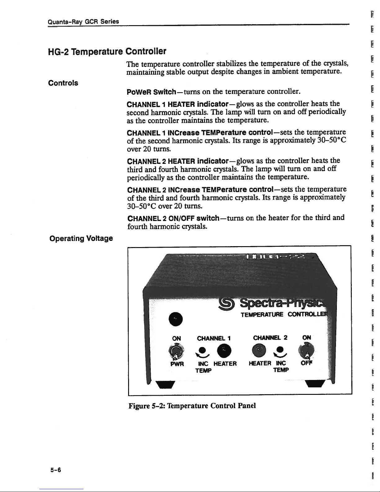
Quanta—Ray
GCR
Series
HG-2
Controls
Temperature
Controller
temperature
The
maintaining
PoWeR
CHANNEL
second
as
CHANNEL
of
over
CHANNEL
third
periodically
CHANNEL
of
30—50°C
CHANNEL
fourth
Switch—turns
harmonic
controller
the
second
the
turns.
20
and
third
the
harmonic
over
stable
HEATER
1
INCrease
1
harmonic
HEATER
2
fourth
as
INCrease
2
and
ON/OFF
2
controller
output
crystals.
maintains
harmonic
controller
the
fourth
turns.
20
crystals.
stabilizes
despite
on
the
indicator—glows
The
the
TEMPerature
crystals.
indicator—glows
crystals.
TEMPerature
harmonic
switch—turns
changes
temperature
lamp
temperature.
Its
The
maintains
crystals.
the
temperature
in
controller.
the
as
will
turn
control—sets
range
is
the
as
lamp
the
temperature.
control—sets
Its
heater
the
on
of
ambient
controller
on
approximately
controller
will
range
temperature.
off
and
the
on
turn
the
approximately
is
the
for
temperature
temperature
crystals,
the
the
heats
periodically
30—50°C
and
third
the
off
and
heats
fr
Operating
Voltage
Figure
I
5—2:
ON
PWR
w
Temperature
CHANNEL
HEATER
INC
TEMP
Control
U
TEMPERATURE
1
CHANNEL
HEATER
Panel
—
CONTROLIJ
2
INC
TEMP
5-6
Harmonic
Generator
Second
Third
Harmonic
Fourth Harmonic
and
The
temperature
operation.
1.
Remove
2.
Find the
the
the
The
3.
•
•
4.
Replace
(TypesIand
Generation
1.
Turn on
2.
Select
and
Turn
3.
the
controller
To
change
the
coverofthe
voltage
transformer.
power
115 V—
230
fuse
line
must
1/8Aslow-blow;
V—1/16
the
cover.
voltage.
also
operating
the
selector,
Slide
the
match
A
slow-blow;
II),
the
controller
crystals
and
and
output
5—2.
on
the
laser
and
adjust
wavelengthofinterest.
factory-set
is
voltage:
temperature
which
is
switchsothe
the input
the
channel
polarization
HG-2
the
for
either
115or230Vac
controller.
located between the
voltage
displayed
voltage:
two
heater.
describedinTables
as
for
maximum
fuse
matches
output
and
5—1
at
4.
Watch
minutes
odically
to
make
If
control
for
If
its
should
The
5.
to
its
At
nel2heater,
the
while
when
room
temperature
sure
either
lamp
clockwise.
a
short
either
INC
lamp
TEMP
stay
fourth
generating
critical
this
point,
HEATER
indicators.
the
crystals
the
temperature
as
the
crystal
shuts
temperature
off
and
The lamp
time,
and blink
continues
pot
counterclockwise
off
forashort
hannonic
ciystalistemperature
UV,italso
phase-matching
either
and
reduce
let
the
They should
warm
is
possible,
stays
should
after
glow
to
time
absorbs
angle
input
the
crystal
up.
Both
stable.
but
Try
monitor
remains stable.
that
way,
on, glow
turn
that.
after
10
mmofoperation,
until
the
and
blink
it.
When
and
output
power or
cool
off.
remain
lamps
to
turn
on
will
operate
the
indicators
the
for
blink
INC
continuously
lamp
after
dependant.
too
power
shuts
that.
In
warmitapproaches
will
turn
off
the
several
peri
close
as
to
TEMP
turn
off.
It
addition
diminish.
Chan
5—7
Chapter
6
Maintenance
Maintaining
Maintaining
Maintaining
the
the
the
Cooling
1.
2.
3.
Air
Purge
1.
HG-2
System
Circulate
the
laser
Inspect
power
with
Replace
deionizing
“Replacing
the
supply
distilled
the
System
air
The
control
ing
the
bly,
Refer
slots
color
oil
to
panel,
ifiter,
filter
above
“Replacing
water
is
not
water
cover.
water
deionizing
filter
the
assembly,
can
changes
and
through
in
use.
level
in
Keep
every
filter
has
changed
Deionizing
which
seen
be
purge
the
from
blue
particle
the
the
system
the
the
three
when
Water
through
controls.
to
ifiter
Air
Filter
reservoir
reservoir
months.
all
color
is
to
Filter”
mounted
the
As
pink.
when
Assembly”
for
30
through
at
the
yellow
light
below.
behind
horizontal
its
desiccant
Change
the
desiccant
mm
least
brown.
the
below.
every
the
half
resin
Refer
the
row
is
air
is
week
slot
full.
in
power
consumed,
filter
exhausted.
in
the
of
ventilat
when
the
Replace
to
supply
assem
1.
2.
3.
not
Do
factory-trained
Keep
Check
it
Use
tissue
attempt
the
the
changes
only
to
crystals
condition
from
spectroscopic
clean
remove,
to
service
sealed
blue
window
WARNING
engineers
and
of
the
to
pink.
grade
surfaces.
replace,
heated
desiccant
methanol
to
or
open
at
add
all
daily;
and
crystals.
your
HG-2.
times.
have
it
photographic
Allow
replaced
only
when
lens
6—1
Quanta—Ray
GCR
b
Series
RepIacng
Procedure
Delonizing
the
prevent
To
pump
while
water
of
filter
part
Tools
•
•
•
•
•
•
1.
Water
lose
to
water
spillage.
cartridge
number
needed:
Medium
in.
3/32
in.
9/64
Small
Small
absorbent
An
Remove
head
screws
side,
each
panel.
from
air
prime,
stifi
is
with
for
flat
Allen
Allen
cork
bucket
the
and
Lift
Filter
in
The
the
blade
wrench
wrench
for
towel
power
in
the
getting
deionizing
the
system.
the
following
minimum
cartridge.
screwdriver
plugging
supply
handle
each
four
the
cover
off.
into
Doing
procedure
chance
end
cover
screws
the
of
well,
on
cartridge
means
so
will
spillage.
of
removing
by
two
the
the
pump
water
filter
cartridge
and
there
allow
Table
screws
perimeter
causing
must
you
the
at
of
be
the
is
to
7—2
three
the
the
the
replaced
possibility
replace
the
lists
button
of
base
control
the
2.
3.
4.
Loosen
leaving
filter
the
of
edge
it
Tape
with
ing
Support
Allen
frame.
the
pull
water
the
Place
water
tridge
in
filter
leave
the
for
Quickly
water
cartridge
hose
the
clamp
the
cartridge.
plastic
the
place
in
cork.
the
filter
the
screws
head
Lower
cartridge
reservoir.
towel
a
that
may
removed.
is
will
(it
the
on
it
pump),
place
leaking
from
upside-down
clamp
to
the
under
leak
be
hose.
and
your
at
the
on
Keep
shroud
insure
assembly
holding
assembly
filter
between
out
it
Lay
filter’s
the
from
of
Hold
twist
finger
out
in
a
and,
Have
full
the
top
hose,
hose
the
prevent
to
stays
it
with
the
down
hose
the
small
water).
onto
pull
and
over
at
the
bucket.
the
of
remove
there.
one
filter
below
the
horizontally.
bottom
bucket
Loosen
the
the
almost
the
vertical,
water
Plug
hand,
bracket
vertical
cartridge
or
hose
cartridge
the
end
the
filter
the
hose
close
the
(to
of
hose
and
from
the
and
to
top
frame
clamp
by
hose
provide
the
same
cartridge
from
it
hang
leaking
cartridge
remove
power
the
frame
member
to
when
put
to
clamp
of
free
to
hose
time,
and,
the
over
from
the
plate,
catch
the
car
the
but
strain
the
prevent
place
of
top
the
open
two
supply
and
and
any
used
relief
hose.
the
it.
6—2

5.
6.
7.
8.
9.
10.
11.
Attach
cartridge.
upright
Loosen
cartridge.
not
Do
Place
fits
ing
around
place
Attach
Pull
long
the
Turn
ever
Replace
the
properly
the
and
the
neck
hose.
the
drops
the
bottom
Water
and
the
Remove
tighten
new
bottom
it.
Replace
tighten
the
upper
return
funnel
pump
below
the
tighten
large
the
cartridge
next
hose,
hose
on
power
will
steel
the
to
the
the
hose
to
and
half,
supply
hose
begin
the
steel
the
hold
steel
out
fill
to
the
to
hose
clamp
bracket,
clamp
into
the
vertical
the
Allen
clamp.
the
to
of
the
the
reservoir
let
it
turn
off
cover.
carbon
flow
clamp.
holding
and
yet.
frame,
frame
filter
screws
filter
water
run
for
the
granule
into
the
the
install
it
and
member.
while
that
hold
Insure
assembly.
pump
reservoir
with
distilled
10
mm.
the
and
end
filter.
filter
bracket
on
the
orient
To
rotating
the
assembly
cap,
If
the
add
of
Stand
new
it
so
prevent
the
bracket
and
water.
reservoir
more
Maintenance
a
new
filter
the
filter
the
to
cartridge.
the
bracket
is
use
Re-insert
water.
old
bracket
twist
in
secure.
a
level
Replacing
Procedure
the
Air
Filters
The
cant
ually.
Tools
•
Medium
•
9164
•
3/32
1.
Remove
head
each
panel.
2.
Remove
of
hose
air
3.
Support
Allen
bottom
from
three
filter
Table
needed:
in.
in.
the
from
hose
the
air
filters:
assembly,
7—2
flat
Allen
Allen
the
screws
side,
and
Lift
the
the
flow
gauge
the
from
the
head
screws
the
of
supply.
input
should
lists
the
blade
wrench
wrench
power
in
each
the
four
cover
retaining
(left
flow
the
small
filter
assembly
holding
top
tray.
oil
filter,
replaced
be
part
numbers
screwdriver
supply
handle
gauge.
off.
pin
side
cover
screws
that
of
In
air
hose
with
the
Lower
well,
output
by
the
on
holds
power
like
manner,
(right
one
desiccant
the
particle
one
at
for
these
removing
two
the
perimeter
the
supply),
side
hand,
filter
filter,
time
components.
the
screws
inlet
air
and
separate
of
power
and
remove
filter
brackets
assembly,
and
not
three
at
the
of
the
hose
separate
the
supply).
and
and
desic
individ
button
base
control
to
the
large
the
the
to
remove
of
top
the
outlet
four
it
6—3
Quanta-Ray
GCR
Series
Replacing
the
Flash
Lay
4.
components
The
end
endofthe
old
Loosen
5.
brackets
new
clamps.
Follow
6.
into
slideabit
to
clamps.
7.
Follow
and
Lamps
For
optimal
of
operation.
directly
the
new
small
with
filter
the
desiccant
components
the
from
one,
noting
step
the
power
on
match
thoseinthe
steps1and
replace
performance,
Table
from
Spectra-Physics.
filter
(note
marked
longest
and
large
the
3
above
supply
the
the
power
7—2
components
directionsofthe
the
“Grade
hose),
filter.
attach
clamps
band
desiccant
old
proper
orientation.
in
reverse
and
desiccant
tray.
in
reverse
2
supply cover.
the
provides
outina
BK”
andisconnect
Remove
the
theminlike
and
remove
cartridge.
ordertoplace
secure
it.
The
cartridge
Once
secured,
order
lamps
should
part
numbers for
manner
arrows
goes
hoses
manner
Do
to
to
allow
on
on
the
to
the
and
the
Attach
not
tighten
the
brackets
the
tighten
reconnect
replaced
be
ordering
similar
the
small
input
to the
end
carbon
fittings
to
two
them
from
the
new
mounting
to
the
band
new assembly
may
have
mounting
the band
the
air hoses
after
lamps
old
filters).
(the
granule
the
ones.
the
to
holes
550
hrs
Procedure
1.
Turn
Allow
As
an
nect
2.
Remove
high
terminal
3.
Disconnect
4.
Disconnect the
assembly. This
into
the
Prevent
could
off
the
laser
mm.
5—10
extra
precaution,
the
power
the
cover
voltage
shield
posts
lamp
power
water from
contaminate
and
open
the
for
all
capacitors
DANGER.
HIGH
open
cord.
the
from
that
laser
covers
A andB(Figure
leads from the
water
will
hose
allow
located
the
waterinthe
supply.
WARNING
flowing
the
face
down
of
power
to
VOLTAGE
the
circuit
head,
the
lamp
6—1)
terminal
onto
the
Nd:YAG
supply
discharge.
breaker
then
housings.
on each
posts.
at
the top of the
head to
the
dust
rod.
circuit
and
remove
pump
drain
tube,
breakers.
discon
the
Short
chamber.
lamp
back
which
plastic
together
house
6—4

Maintenance
Figure
6—1:
servicing
5.
Loosen
of
the
Remove
6.
7.
Handle
touchingitwith
Reverse
8.
Insert
identified
anode
trode
Make
lamp
Tighten
Connect
9.
Short
the
flash
and
lamps.
the
the
steps
lamp
the
by
lead.
is
segmented
sure
all
housing.
all
thumb
the
together
posts
lamps.
remove
the
thumb
lampsbypulling
flash
new
one
a
The
your
cathode
red
0-rings
fingers.
through
mark
anode
and
lamps
end
on
electrode
cone-shaped.
are
screws
water
hose
to
A
it
using
Clean
six
to
(black
its
seated
evenly
the
B
and
to
screws
out
anode
white
the
install
lead)
electrode
is
solid,
snugly
snugly.
and
of
top
prevent
and
nylon
new
a
in
the
block
end
lamps
new
first.
and
while
the
rod
an
Do
from
lead)
with
when
both
avoid
methanol.
shock
(red
gloves;
lamps.
anode
The
the
on
“A’
cathode
the
grooveofthe
overtighten.
not
assemblies.
ends
first.
end
red
is
elec
6—5

Quanta-Ray
GCR
Series
10.
After
installation,
interlock,
ing
water
water
leaks
the
If
in
the
cover
leak
a
step
lamp
pump
after
then
into
5
interlock,
occurs,
one.
in
test
press
the
and
inspect
sec.,
the
turn
Remove
its
housing.
the
lamp
and
off
the
for
water
ON
housing.
again
seals
install
the
thumb
Check
button
are
laser,
leaks
If
full
at
tight.
the
screws
the
follows:
as
long
enough
no
leaks
pressure.
Turn
off
laser
head
observing
and
seating
occur,
If
the
cover.
the
blocks,
of
the
defeat
to
turn
there
laser,
danger
then
0-rings.
the
move
are
activate
cover
cool
the
on
no
warning
center
6—6
I
I

Chapter
7
Service
and
Repair
System
COMPUTER/INTernal
Enabling
Description
Signals
Figures
and
control
are
located
Switch
Selects
module
Enabling
lamp
mode,
operation.
directly.
the
Interface
either
If
the
RS-232-C
only
firing,
choice
RS-232-C
7—1,
7—2,
board
at
as
the
CIM-1
one
signals
choice
The
When
Module
and
7—3
—the
assembly—illustrate
end
the
optional
the
control
option
and
may
be
control
of
of
single-shot
remote
CIM4
the
or
IEEE
(CIM-1),”
of
unit.
IEEE
used
lamp
488
this
CIM-1
is
488
at
laser
control
option
system
section.
interface
NOTE
included
interfaces
time).
a
start-up,
trigger
or
repetitive
module
is
interface.
for
instructions.
block
the
as
part
are
analog
oscillator,
operation,
supplies
used,
Refer
commands
to
diagram,
following
or
the
remote
of
the
selected
strobe
Q-switch
enabling
Chapter
schematic,
discussion.
control
system,
(although
triggering,
triggering
and
single-shot
signals
may
be
4,
“Computer
the
sent
All
flash
via
Analog
Signals
Analog
tor,
the
advanced
voltages
signals
The
analog
trolled,
The
laser
High
tion.
jumper
5
msec
transfer
voltages
Q-switch
sync
signal.
directly.
directly
depending
#1
gate
from
strobe
shipped
was
current
its
to
aperture.
the
as
control
triggering
The
commanded
function
on
provides
alternative
computer
the
The
CIM-1
placement
from
This
flash
lamp
delay,
remote
can
the
continuous
configuration
mode
bus
and
control
interface
the
by
be
either
of
jumper
factory
will
with
a
accept
energy,
the
timing
module
module
attached
edge-triggered
in
a
analog
allows
time
supplies
computer
#1
on
level
data
edge
triggered
restricted
the
variable
of
the
supplies
or
the
control
controlled
transfer.
triggering
analog
window.
oscilla
Q-switch
analog
these
analog
or
terminal.
level
board.
configura
Changing
of
data
con
a
7—1

Quanta-Ray
GCR
Series
Q-switch
0-switch
Delay
Advanced
Under
turned
ground.
lator
the
After
passes
form
Q-switch
sion
the
Sync
The
and one
controls
ADVance
delay
compared.
is
form
rise
shorting
by
data.
firing
control,
computer
on,
signal
a
the
internal
off
Under
turned
is
analog
the
through
to
meet
delay.
develop
to
peakofstored
Generator
signal
splits,
voltage
timing
the
SYNC
provides
the
The
to
time
meet
output
=
20
nsec,
the
analog
the
ANALOG
control,
then
data
data
Held
will
emerges
drive
150—500
regeneration
requirements
Q-switch
pulse
This
before
energy.
passing
through
programmable
of
“pretrigger”
the
connector
timing
reference
advance
signal
5
V.
strobe
STROBE
analog
flow
untilitis
will
typically
the
from
one-shot
of
delay
lisec
triggering,
pair
a
(300—1300
the
on
power
against
pulse
sync
requirements:
is
wired
strobe
drift
computer
the
allows
delays,
of
signal
supply
generator
“on.”
is
connector
off
until
off,
10%
IIPTJT
turned
about
test
shapes
that
voltage-programmable
the
population
so
the
Q-switch
fIxed
one
psec).
at
The
the
Q-SWitch
panel.
which
the
shapes
pulse
width
It
can
its
which
in8mm.
delay,
the
opens at
(800
variable
The
fixed
variable
the
=
5
be
to
optoiso
stores
it
wave
inver
nsec)
delay
delay
wave
msec,
Mode
Switch
(Ull)
function
This
In
the
0-SWitch
delay
sion.
cell
pulse.
INPUT
The
opens
The
simultaneously,
In
on
source
enables
the
LONG
EXTERNAL
the
power
the
of
the
mode,
Q-switch
PULSE
holding
enabling
COMPUTER/INTernal
CIM-1
remote
the
computer
Q-switch
connector,
installed and
is
control
module
is
triggering
regardless
the
source
signals
switch.
of
one
a
signal
momentarily
mode
mode,
supply
signal
switch,
remote
the
supplies
under
enter
of
the
three
sources
from
triggers
the
Q-switch
a
panel
depends
is
or
the
COMPUTER
through
position
the
at
the
signal
fires
from
control
signal
of
of
Q-switch
trigger
voltage-programmable
the
point
flash
open
the
at
Pockels
the
on
the
the
computer
jumper
under
the
0-SW
COMPUTER/INTernal
the
maximum
of
lamp
and
throughout
Q-SWitch
cell.
position
if
plugisused.
INTernal
control.
All
TRIG INPUT
TRIGger
the
signals.
inver
Pockels
the
lamp
the
of
optional
The
control;
external
*
I
7—2

Service
and
Repair
Q-switch
Single-Shot
Drivers
Operation
The
mode
is
a
pulse
which
pulse
output
generator
the
enabled)
a
produces
tortoproduce
connector
V
5
(5
Firing
shot
either
SHOT
come
the
remote
allow
armed
The
under
without
select
at
a
programmed
on
msec
single
a
flip-flop
computer
the
switch
from
either
control
the
next
again,
single-shot
computer
adversely
the
10
fixed
and
few
a
the
and
shot
and
on
available
the
function
Hz
delay
fires
psec
long
the
signal
stretches
signal
that
power
200
psec
requires
onetofire
(pins
remote
the
computer
the
panel.
flip-flop
control,
affecting
oscillator
rate.
passes
the
Marx
through
bank
thatisamplified
that
drives
output
the
appears
supply
rise
27
and
two
it.
and
time).
The
at
signals:
17)orthe
control
(pins
Once
pulse
prevents
operates
can
armed,
to
fire
the
with
be
usedtovary
focusing
the
at
lamp
pulse
the
of
the
at
the
the
origin
panel.
and
6
the
the
passage
all
of
the
source,
the
mode
switch
generator.
the
by
Marx
Marx
0-SW
computer
one
of
bank.
to
the
Marx
bank
SYNC
connector
enable
enabling
The
pulse
REPetitive/SINGLE
The
5)
or
single-shot
Marx
trigger
the
Nd:YAG
then
firing
bank.
of
signal
the
FIRE
circuit
Until
subsequent
sources,
pulse
repetition
rod.
fire
(Q-switch
result
The
bank
buffer,
Q-switch
genera
OUTPUT
(pin
the
single-
signal
can
button
will
it
is
pulses.
and
To
do
single
shots
46):
is
on
when
rate
so,
Inhibit
OFF
Switch
[STOP]/ON
Applies
prevent
an
OR
remains
shut
[ENABLE]
Function
switch,
remote
the
ON
cuits
control,
(ON)
option)
the
laser.
regardless
The
line
until
errors
voltage
lamp
gate
active
off
at
buttons
depends
or
control
button
and,
both
button
and
The
line
dropout
voltage.
all
power
logic
in
that
the
is
hard
after
(or
an
of
The
to
firing.
allows
under
remote
on
wired
jumper
closes
a
10
an
enabling
using
“on”
lighted
the
position
detector
initializing
supplies
start-up.
the
reset
The
either
computer
control
the
“on”
plug
the
sec
the
signal
buttons
have
line
inhibit
position
is
main
delay,
signal,
remote
from
identify
of
the
will
circuits
of
the
lamp
sync
and
of
them
control,
source
to
so
fault
inhibit
the
panel.
of
the
COMPUTER/INTernal
if
the
CIM-1
used.
relay,
starting
derived
control
the
computer
Under
the
option
internal
activating
the
laser.
pressing
by
jumper
are
operating
COMPUTER/INTernal
shut
off
the
laser
prevent
energized,
transfer
preventing
pulse
signals
firing.
laser
is
all
Under
plug
required
status
if
it
generator
pass
The
always
can
installed
control,
power
computer
ENABLE
the
with
of
switch.
senses
laser
of
mishaps
through
switch
and
pressing
supply
CIM-1
the
turn
to
the
loss
a
control
due
to
be
the
cir
on
laser,
of
to
7—3

Quanta-Ray
GCR
Series
Interlock
Logic
interlock
The
operation:
free
switches,
flow.
The
tion
lock
off
logic
The
will
nearly
put
If
delay,
If
environmental
of
fault
powertothe
power
logic
prevent
zero
upon
interlock
no
and
one
or
“interlock
the
remote
external
The
and it
must
interlock:
interlock loop
the
lockisa
shielded
the
laser
logic
external
cooling
water
external
discovered,
is
switching
on.
also
receives
starting
upon start-up.
start-up.
faults
after
10
more faults
fault”
signal
control
interlock
wired
be
grounding
possible
in
hostile
case
sourceofnoise,
near
examines
several
interlock,
temperature
interlock
safety
connectorisincluded for
devices
the
logic
supply
input from
the
laser
until
This
are detected, the
the laser
sec,
are
detected,
will
appear
panel.
connector
usingatwisted
will
blowafuseinthe
and
prevents
environments.
the
external
sensorstoensure
head
and
and
laser
and
flow,
switching
power
safe,
supply cover
supply
simple
suchasa
trips
and
the
the
prevents
will
start.
the
at
operates
wire
the
simmer
lamp
lamp
logic
laser
the
door
switch.Ifan
main
contactor,
transformer,
voltage
level
energyisreduced
accidental
high
enables
will
not
computer
from
pair.
bus
the
15Vpower
Do
not
15Vsupply,
the
start,
ground
shutting
leaving
sensor;
power
turn-on
and
(pin
which
starting the laser. The external
and the
This
interlock
twisted
shield
connector.
should
wire
pair
be grounded to
trouble-
air
installa
inter
it
to
out
an
and
48)
supply,
the
opens
inter
should be
Pulse
Forming
Network
The
pulse
forming
the silicon-controlled
flash
lamps
The
switching
into
dc
age
(V)
It
can
the
RS-232-CorIEEE
tional
provided
CIM-1
Safety
the
energy
switched
that
voltage
is
be
set
CIM-1
pin
at
interface
circuits
storage
off.
pumps
power
for
programmable:
either
computer
20
of
(refer
associated
network
rectifier
the
supply
the
pulse
with
the
488
interface
computer
the
to
Chapter4for
with
capacitor.
producesacritically
(SCR)isfired.
Nd:YAG
rods.
transforms
forming
Vf
=
remote
interface
if
module.
interface,
line
network
225
control
your
A
•
V,
PFN
This
voltage
module
system
0to8
details).
the
pulse forming
This
will
occur
when the
damped
pulse
(PFN).
where
includes
voltage
V,
network
pulse
drives
when
the
(208V,nominal)
The
PFN
volt
V
=
or
and
will
laser
0to8
via
monitor
also
V.
either
the
op
is
via
the
discharge
is
I
7—4
Service
and
Repair
The
complete
Avoid
long
the
charge.
can
measures.
Circuitry
voltage
An
indicator
nector
breaker
lamp
The
generator,
pulse
el,
and
SCR
The
pulse
the
generator
pulse
capacitor
contact
after
capacitor
Please
explode
within
drops,
located
glows
to
override.
to
sync
the
“lamp
pulse
transformer
DANGER.
discharges
discharge,
with
turning
off
may
note
discharged
when
the
switching
which
can
next
indicate
pulse
generator
LAMP
the
triggered”
generator
for
the
to
and
lamp
the
then
be
that
cause
to
a
low
SYNC
conditions
SCR
fire
HIGH
slowly,
no
voltage
or
capacitor
power.
shorted
charged,
in
this
supply
SCR
switching
the
line
condition;
provides
OUTPUT
monitor
driver.
the
SCR.
VOLTAGE
requiring
terminals
an
As
additional
remove
to
large
manner,
monitors
failure,
supply
a5msec
on
the
the
output
This
sends
at
least
monitor
for
any
electrolytic
so
take
line voltage.
the
supply
control
reset
the
signal
on
the
power
computer
of
the
a
1Apulse
1
mm
is
available.
at
least
precaution,
remaining
capacitors
appropriate
If
will
shut
input
main
to
the
supply
(pin
47).
lamp
sync
through
for
that
the
off.
con
circuit
SCR
pan
Flash
System
Lamp
Start-up
Simmer
Supply
This
supply
the
Marx
mer current
couples
down
off
ing
the
the start
the
Tests
The
following
start-up
source
Spectra-Physics
system.
of
provides
bank
sensor
a
high
lamp.
circuit.
simmer
of
the
system
(500
voltage
After
supply
table
GCR.
failure.
field
voltage
V),
and
activates
pulse
the
lamp
Refer
via
the
describes
They
Use
service
the
to
the
the
flash
flash
start
through
starts,
to
Chapter
optional
events
are intended
the results
engineer
lamp
lamp
circuit,
the
lamp
simmer
4
for
CIM-1
that
as
of
quickly
start
simmer
which
housing,
current
information
module.
occur
a
guide
this
during
test
isolate
circuit
(200
current.
capacitively
breaking
flows,
on
monitor
a
normal
for
identifying
help
to
and
your
repair
V),
The
sim
shutting
your
the
7—5

Quanta-Ray
GCR
Series
Table
7—1:
Action
Close
breaker
the
Press
on
module
Turn
control
clockwise
key
the
the
LAMP
the
remote
System
power
and
switch.
ON
ENERGY
fully
line
turn
on
button
control
counter-
Start-up
Turns
the
LOCK
nience
Turns
panied
fan,
on
Turns
lished
Tests
on
power
remote
FAULT
outlets
on
the
by
a
power
the
EMISSION
off
INTERLOCK
(about2sec).
Initiatesa10
After
foraloud
is
supply;
10
applied
the
sec
click.
to
operational. LEDs
and
three
(P.S.
operating
control
mode*;
PC
Afterahalf-second
establishing
result,
a
and
lock plug
noticeable
supply
The
the
control
laser
the
dump
and
click.
is
energy.
the
to
control
module
lamps
at
110Vac.
ON lamp
small
supply
start
sec
K2
the
noise;
fan,
ENABLE
safety
closes,
All
simmer
circuit,
one
INHIBIT)
the
board.
delay
the
simmer current;
SIMMER
relay
the
large
LED
PC
board,
fully
operational
control
on
the
on
starts
laser
FAULT
delay,
pulling
timing
transformer
the
(Q-SW
flash
LEDs
the
indicator
(K502),
grey
four
glows
Result
PC
board;
and
both
the
power
the
head
lamp
remote
the
water
fan;
lamp
supply.
control;
enables
the
on
when
provided
in
the
main
logic
becomes
and
Marx
are
start
bank,
ADV
when
located
circuit
the
on
SYNC), two
the
start
the
located between
capacitor
(P.S.
ON/OFF),
(C504),
continuously.
at
this
point;
lights
POWER
Energizes
closes
pump,
the
laser
water
no
interlock
contactor
operational;
switching
the
and
its
laserisin
on
the power
ignites
circuit
remote
the
pulls
also on
increase
OFF
the
and
lamp
INTER-
all
conve
K3,
exchanger
heat
air
pump;
head.
is
flow
fault
(K1);
ac
power
trigger
become
(Q-SW
the
normal
supply
the
flash
stops pulsing.
control
turns
auxiliary
in
with
the power
the
lamp
on
accom
turns
estab
exists.
listen
power
SYNC),
lamp,
As
on,
inter
a
by
to
Normal
failure
the
turning
switch
Operating
flash
on
Mode
Interlock
Inhibiting
lamp
the LAMP
*
Refer
7—6
K2
opens,
FAIL
indicator
C504;
turns
remain
To
all
off;
on.
restore
ENERGY
Inhibits
lamp
turn
supply.
turns
off.
the
Logic
LEDs
the normal
Settings
next
de-energizing
turns
logic
shuts
the
start
operation,
control
to
drivertothe
on,
and
command
one
and
operating
page.
Ki
on;
the
LED
off;
circuit
clear
zero
pulse forming
the
flash
shuts
two
mode.*
with
dump
four turns
power
the
interlock
(fully
counterclockwise).
lamp
off power
continue
loud
a
relay
turns
shuts
click;
drops
off;
off;
fault
network
off.
from
to flash
the
out
the
Marx
all
pumps
and turn
SCR;
LEDs
the
when
INTERLOCK
to discharge
bank
power
and fans
the
LAMP
the
INhIBIT
three
switching
the
and four
laser
power
is
in
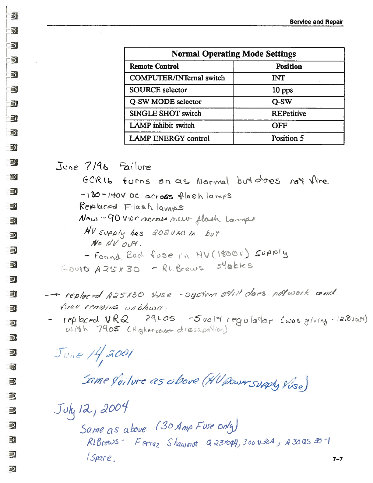
Sb
cJ
U)
a)
—
5-
D
c7
C
:
-d
cf)
6
V
Q)
C
0
(U
a)
(U
0.
&
L)
-
C)
C)
•____*%.
4<
-
(11
-
t
:3)
—U
‘3
ii
r
*
1
4—.
s
\
c-i
-
—
4—
—Th
L
r
•1
i
V)
r)
9Hi
V
F
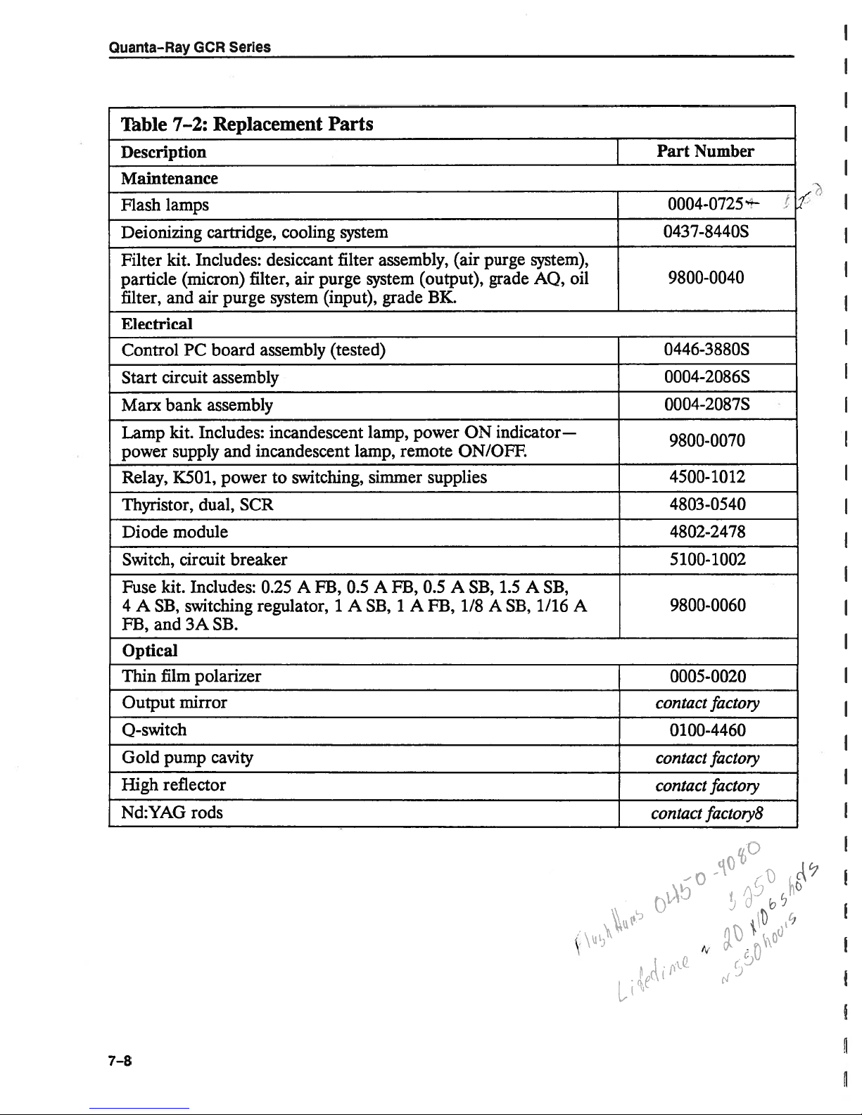
Quanta-Ray
GCR
Series
Table
7—2:
Description
Maintenance
Flash
Deionizing
Filter
particle
filter,
lamps
kit.
(micron) filter, air
and
Electrical
Control
Start
Marx
Lamp
power
Relay,
Thyristor,
Diode
PC
circuit
bank
kit.
supply
K501,
module
Replacement
cartridge,
Includes:
air
purge
board
assembly
assembly
Includes:
and
power
dual,
desiccant
system
assembly
incandescent
incandescent
to
SCR
cooling
purge
(input),
switching,
Parts
system
filter
(tested)
lamp,
assembly,
system
grade
lamp,
remote
simmer
(output),
BK.
power
supplies
(air
purge
grade
ON
indicator.—
ON/OFE
system),
oil
AQ,
Part
Number
0004-0725
0437-8440S
9800-0040
0446-3880S
0004-2086S
0004-2087S
9800-0070
4500-1012
4803-0540
4802-2478
7
I
Switch,
Fuse
kit.
4
A
SB,
FB,
and
Optical
Thin
film
Output
Q-switch
Gold
High
Nd:YAG
pump
reflector
circuit
Includes:
switching
3A
SB.
polarizer
mirror
cavity
rods
breaker
0.25
regulator,
A
FB,
0.5
A
FB,
1ASB,1A
0.5
FB,
A
SB,
1/8ASB,
1.5
A
SB,
1/16
A
5
100-1002
9800-0060
0005-0020
contact
0100-4460
contact
contact
contact
factoiy
factoiy
factoiy
factoiy8
C)
(
7—8
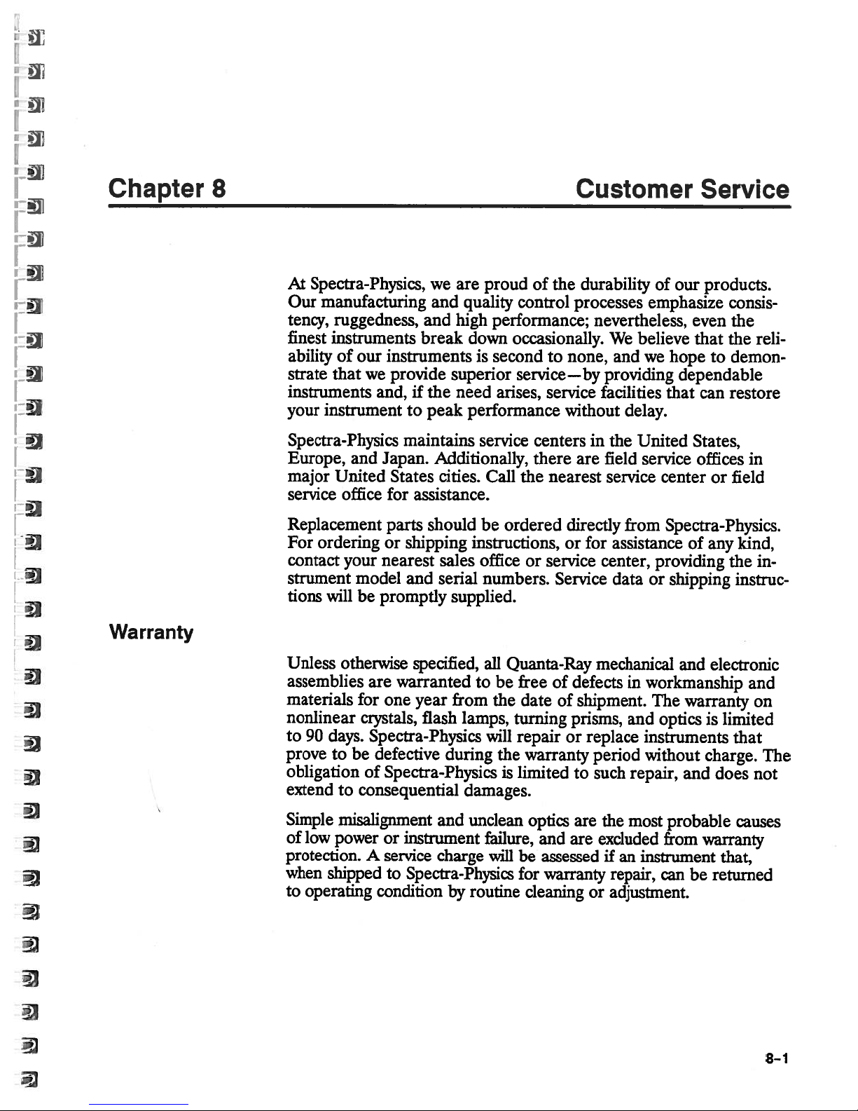
Chapter
8
Customer
Service
Warranty
At Spectra-Physics,
manufacturing
Our
tency,
finest
ability
strate
instruments
your
Spectra-Physics
Europe,
major
service
Replacement
For
contact
strument
tions
Unless
assemblies
materials
nonlinear
to
prove
obligation
extend to
ruggedness,
instruments
of
that
instrument
and
United
office
ordering
your
will
otherwise
90
days.
to
be defective
our
instruments
we
provide
and,
to
maintains
Japan.
States
for assistance.
parts
or
shipping
nearest
model
be
for
crystals,
consequential
and
promptly
are
warranted
one
Spectra-Physics
of
Spectra-Physics
we
are
and
quality
and
high
break
if
down
superior
the
need
peak
performance
Additionally,
cities.
should
instructions,
sales
serial
supplied.
specified,
year
from
flash
lamps,
during
damages.
proud
is
service
Call
be
officeorservice
numbers.
all
to
will
of
the
control
performance;
occasionally.
secondtonone,
service—by
arises,
the
ordered
Quanta-Ray
free
be
the
date
turning
repair
the
warranty
is
limited
service
without
centers
there
nearest
directly
or
Service
of
of
or
processes
defects
prisms,
to
durability
nevertheless,
We
believe
and
providing
facilities
delay.
in
the
United
are
field
service
from
for
assistance
center,
data
mechanical
in
shipment.
and
replace
period
such
repair,
our
of
emphasize
we
service
providing
or
workmanship
The
opticsislimited
instruments
without
products.
even
that
hope
to
dependable
that
can
States,
offices
center
Spectra-Physics.
or
of
any
shipping
and
electronic
warranty
charge.
and
does
consis
the
the
reli
demon
restore
in
field
kind,
the
in
instruc
and
on
that
not
The
Simple
of
protection.Aservice
when
to
misalignment
low
power
shipped
operating
and
or
instrument
charge
to
Spectra-Physics
condition
by
unclean
failure,
will
routine
optics
and
be
assessed
for
warranty
cleaning
are
are
or
excluded
most
the
if
an
instrument that,
repair,
adjustment.
can
probable
from
warranty
be
causes
returned
8-1
Quanta-Ray
Return
of
GCR
the
Series
Instrument
for
I
Repair
Service
Centers
nearest
Contact
or
paid
designed
If
shipping
obtain
Physics
Australia
Spectra-Physics
2-4
Post
Croydon,
Telephone:
Fax:
Belgium
Spectra-Physics
North
Noorderlaan
2030
Telephone:
Fax:
your
distributor
to
the
to
boxes
new
a
will
Jesmond
Office
Victoria
725-4822
(03)
Trade
Antwerp
541-8202
(03)
destination
securely
only
Box
(03)
Building
(03)
for
shipping
have
one,
return
Pty.
Road
141
723-6600
B.V.B.A.
133
541-7515
Spectra-Physics
instructions,
indicated.
instruments
hold
lostordestroyed,
been
nominal
for
a
instruments
Ltd.
3136
field
and
Special
charge,
Spectra-Physics
during
from
in
Spectra-Physics’
sales
office,
forward
shipment
the
recommend
we
Spectra-Physics.
service
instrument
should
containers.
center,
packing
be
that
Spectra-
pre
boxes
used.
you
c
Latin
America
Spectra-Physics
Terra
1330
Post
Office
Mountain
Telephone:
Telephone:
Telex:
Fax:
(415)
France
Spectra-Physics
Avenue
Z.A.
de
BP
28-91941
Telephone:
Telex
Fax:
1.6907
Bella
Box
View,
(800)
(415)
348-488
969-4084
de
Scandinavie
Courtaboeuf
LES
1.6907
601
183
60
and
Lasers
Avenue
7013
CA
456-2552
961-2550
S.A.R.L
UUS
99
93
Pacific
94039-70
Cedex
56
Region
13
8-2

Customer
Service
Service
Centers
(cont..)
Germany and
Spectra-Physics
Siemensstrasse
D-6100
Germany
Telephone:
Telex:
Fax:
Fax:
Japan
Spectra-Physics
15-8
Shibuya-ku,
Telephone:
Telex:
Fax:
The
Spectra-Physics
Prof.
Post
5600
Telephone:
Fax:
419471
(06151)
(06151)
Nanpeidai-cho
2466976
(03)
Netherlands
Dr.
Office
CG
(040)
Export
GmbH
20
Darmstadt
(06151) 708-0
75000
710795
K.K.
Tokyo
3462-4531
(03)
3462-4530
B.V.
Dorgelolaan
Box 2264
Eindhoven
(040)
466097
45
Countries*
150
20
18
55
Switzerland
Spectra-Physics
AG
Hegenheimermattweg
CH-4123
Telephone:
Fax:
Allschwil/Basel
(061)
(061)
481 37
481 84
44
United Kingdom
Spectra-Physics
Boundaiy
Hemel
Herts,
.Hempstead
HP2
Telephone:
Fax:
(0442)
*
CSSR,
Norway,
Sweden,
Denmark,
Ltd.
Way
7SH
(0442)
232322
68538
Egypt,
Pakistan, Portugal,
Turkey,
USSR,
65
00
and
Finland,
Saudi
Yugoslavia.
Greece,
Arabia,
Ireland,
South
Israel,
Africa,
Kuwait,
Spain,
8-3
Quanta-Ray
GCR
Series
Service
Centers
(cont..)
Eastern
Spectra-Physics
255
Old
Piscataway,
Telephone:
Telephone:
Fax:
(908)
Western
Spectra-Physics
1330
Terra
Post
Office
Mountain
Telephone:
Telex:
Fax:
348-488
(415)
United
New
Brunswick
NJ
(800)
921396
981-0029
United
Bella
Box
View,
(800)
964-3584
States
Lasers
Road,
08854-4175
456-2552
States
Lasers
Avenue
7013
CA
94039-7013
456-2552
kc’
J
Suite
N40
I
il
‘1’
‘
t
3c
1Lj
8-4

Spectra-Physics
Lasers
Instruction
Manual—
provided
have
We
Spectra-Physics
your
mal
ested
Thank
or
call
improving
in
you.
From:
Name
Company
Department
Address
Instrument
letter
or
Model
this
form
Lasers
service
our
to
our
products
Institution
Number
encourage
to
instruments
department,
and
you
to
its
or
but
manuals,
us
about
tell
instruction
that
you
we
and
appreciate
Problems
difficulties
any
manual—problems
be
feel
should
remedied.
all
suggestions.
Serial
and
have
you
that
Number
Solutions
experienced
did
not
require
are
always
We
in
using
for
a
inter
Problem:
Suggested
To:
Mail
Spectra-Physics
Quanta-Ray
Terra
1330
Office
Post
Mountain
U.S.A.
Solution(s):
Quality
Bella
Box
View,
Lasers,
Manager
Avenue
7013
94039-70
CA
Inc.
13
 Loading...