

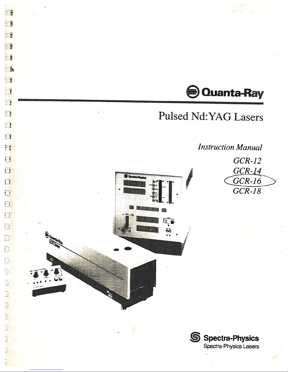
Spectra-Physics Quanta-Ray GCR-16, Quanta-Ray GCR-14, Quanta-Ray GCR-12, Quanta-Ray GCR-18 Instruction Manual
—©
Quanta-Ray
4.’—
Pulsed
,
.
.
iia
)IIIIIlIIIIIflhIIIIiliii
IIlIllhIlllhIllllhIIIfII
IIIllhlIIOhlllllflIllhI
11111
Nd:YAG
Instruction
Lasers
Manual
GCR-12
GCR-L4
GCR-18
Spectra-Physics
SpectraPhysics
Lasers

—©
Quanta-Ray
Pulsed
Nd:YAG
Instruction
Lasers
Manual
GCR-12
GCR-14
GCR-16
GCR-18
Spectra-Physics
Spectra-Physics
Bella
Terra
1330
Post
Office
Mountain
Part
View,CA94039-7013
International
Siemensstrasse
D-61
Number
0000-225A,
Headquarters
00
Lasers
Avenue
7013
Box
Darmstadt
Germany
Rev.
1992
April
20
A

This
manual
operation
Nd:YAG
operation,
contains
and
maintenance
Laser
System. You
preventive
andatroubleshooting
elements—the
tion
to instructions
installation
laser
and
operation
information
you
of your
will
find
maintenance,abrief
and
repair
head
power
for these
of
guide.
supply,
components,
the
HG-2
will
need
QuantaRay®
instructions
descriptionofits
The
system
and
remote
the
manual
harmonic
Preface
for
day-to-day
OCR
for installation,
generator.
Series
circuitiy,
comprises
control. In
describes
three
addi
the
While
this
intended
Please
wait
assigned
those
up
The
you
as
to
failures
The
damage
over,
put
Laser
qualified
your
laser
Service
guide your
guidetorepairs
a
repair
to
OCR
eyes
focused
energy
Safety
hazards.
carefully
If
you
encounter
please let
problems
Physics
instruments.
manual
as
a
for
this
containsabrief
guide
to
the
Spectra-Physics
taskaspartofyour
and
authorized
system.
and
Repair
field
service
you
the
unit
while
Spectra-Physics
Series
can
To
follow
us
to
lasers
and
skin,
back
reflections
destroy
section
minimize
these
any
know.
our
attention.
contains
the
instructions.
difficulty
The
installation
the
initial
installation and
service
purchase agreement.
Spectra-Physicstoinstall
by
sectionisintended
engineer
may
choose
itisunder
customer
emit
laser
ignite
fires,
of
expensive
to
to
warranty;
service
radiation
and vaporize
evenasmall
internal
information
risk
of
injury,
the
with
last
page
isaformtoaidinbringing
Thank
you
procedure,
set-upofyour
engineer
both
as
the
sourceofproblems,
do
yourself.
instead,
for
warranty repair.
that
can
substances.
percentage
optical
and
guidance
death,
content
for
or
or
your
expensive
styleofthis
purchase of
itisnot
who
has
been
Allow
and
an
aidtohelp
not
Do
report
attempt
all
permanently
More
of
its
components.
about
repairs,
manual,
Spectra
laser.
only
set
and
system
out
The
these
such
III
Table
of
Contents
Chapter
Emission
Population
Nd:YAG
Q-switching
Resonant
Longitudinal
Producing
Resonator
Pulse
Specifications
Chapter
Precautions
Focused
Maintenance
in
Compliance
Radiological
Sources
Introduction
1
Absorption
and
Inversion
an
as
Optical
Modes
Other
Structural
Triggering
Laser
2
for
Back
Required
Health
of
Excitation
Cavity
and
Wavelengths
Considerations
Sequence
Safety
Safe
the
Reflection
to
with
Center
(CDRH)
Laser
Safety
Light
of
Medium
Linewidth
and
Timing
Operation
Safety
this
keep
Devices
for
Regulations
Standards
of
Class
Laser
Product...
and
IV-High
Power
Lasers
1—1
1—1
1-3
1-4
1-6
1-7
1-8
1-10
1—11
1-12
1-14
2-1
2-1
2-3
2-3
2-4
Chapter
Unpacking
Installing
Connecting
Filling
Controls
Controls
OUTPUT
lNPUTConnectors
REMOTE
COMPUTER
POWER
PURGE
Power
Installation
3
your
Laser
the
Cooling
the
Connections—Remote
and
and
Connections—Power
Connectors
Connector
Controls
Controls
Supply
Laser
the
Electrical
Connector
Rear
and
System
Panel
Operation
Service
Supply
Control
Module
3—1
3-1
3-1
3-1
3-2
3-3
3-5
3-5
3-5
3-6
3-6
3-6
3-7
3-7
V

Table
Contents
of
(cont.)
Chapter
Controls
Q-switch
Emission
Convenience
Starting
Chapter
Functional
Computer
IEEE
RS-232-C
Message
CIM-1
Examples
Example
Installation
3
Connections—Laser
and
Driver
Indicator
Laser
the
Computer
4
Overview
Control
Power-On
Computer
488
Operation
Remote
Serial
SW2
Operation
Data
SW1
SW3
Command
Response
Commands
CONFIGURE
SAMPLE
SELECTc
WRITEp,n
SELECT
SELECT
SELECT
SELECT
SETd,n
External
Variable
Q-switch
Sample
Default
Safety
Interface
Reset
Status
Poll
Switch
DIP
Serial
Transfer
DIP
Switch
DIP
Switch
Formats
Format
a
1,
1,
1,
1,
lamp
rep
Advance
Analog-to-Digital
Commands
(Marx
Receptacle
and
State
(Watchdog)
Byte
Setting
Interface
and
Setting
Setting
Format
OUTPUT,
p,
WRITE
WRITE
WRITE
WRITE
fire
rate
Operation
and
Bank)
Box
Interface
Diagnostic
System
and
Handshaking
NONCLOCKED
4,
n
n
5,
n
6,
7,
n
Sync
Conversion
Using
GW
Head
Module
Functions
Interlock
BASIC
(cont..)
Initialization
a
Personal
on
Computer
3-1
3-8
3-8
3-8
3-8
3-9
4-1
4-1
4-3
4-3
4-4
4-4
4-4
4-4
4-5
4-6
4-6
4-6
4-7
4-8
4-8
4-8
4-8
4-9
4-10
4-10
4-11
4-11
4-13
4-13
4-13
4-13
4-15
4-15
4-15
4-15
4-16
4-17
4-18
VI
Chapter
Installing
5
HG-2
and
Harmonic
Operating
Generator
the
TableofContents
(cont.)
5-1
HG-2
Installing
Operation
TypeIandIICrystals
HG-2
Controls
Operating
Second
Third
Chapter6
Maintaining
Maintaining
Maintaining
Replacing
Procedure
Replacing
Procedure
Replacing
Procedure
Controls
the
Temperature
Voltage
Harmonic
and
Fourth
Maintenance
the
Cooling
Air
the
the
HG-2
the
Deionizing
the
Air
Flash
the
HG-2
Controller
Harmonic
Purge
Filters
Lamps
(TypesIand
Generation
System
System
Water
Filter
II)
5-3
5-3
5-4
5-5
5-6
5-6
5-6
5-7
6—1
6-1
6-i
6-i
6-2
6-2
6-3
6-3
6-4
6-4
Chapter7ServiceandRepair
System
System
Description
Computer/Internal
Enabling
Analog
Q-switch
Q-switch
Mode
Q-switch
Single-Shot
Inhibit
OFF
Interlock
Pulse
Flash
Signals
Signals
Delay
Advanced
Switch
Switch
[STOP]/ON
Forming
Lamp
Start-up
(Ui
Drivers
Operation
Logic
Simmer
Tests
Network
Switch
Sync
1)
[ENABLE]
Supply
Generator
buttons
7-1
7-i
7-1
7-i
7-1
7-2
7-2
7-2
7-3
7-3
7-3
7-3
7-4
7-4
7-5
7-5
VII

Table
Contents
of
(cont.)
ChapterlOCustomerService
Warranty
Instrument
the
Centers
Electrons
probability
the
radial
A
Compared
Energy
The
polarization
Stable
Frequency
Etaton
Simplified
Radiation
Warning
Main
Cooling
Remote
Power
Q-switch
Head
Location
Diagram
Standard
Command
4-4:
CIM-1
4-5:
HG-2
5-1:
Temperature
5-2:
Short
6-1:
when
occupy
of
shape
Typical
of
and
Four-level
angular
Level
Q-switch
and
Loss
Block
Control
Labels
autotransformer
System
Control
Supply
Driver
Emission
of
of
RS-232-C
Proprietary
Component
together
servicing
to
rotator,
Unstable
Distribution
CIM-1
the
Word
List
Return
Service
Figures
of
Figure
Figure
Figure
Figure
Figure
Figure
Figure
Figure
Figure
Figure
Figure
Figure
Figure
Figure
Figure
Figure
Figure
Figure
Figure
Figure
Figure
Figure
Figure
Figure
of
1-1:
1-2:
1-3:
1-4:
1-5:
1-6:
1-7:
1-8:
2-1:
2-2:
3-1:
3-2:
3-3:
3-4:
3-5:
3-6:
4-1:
4-2:
4-3:
Repair
for
distinct
finding
the
orbital
dependence
Transition
of
that
Scheme
comprises
and
Minimum
Diagram
Drawing
Component
Panel
Control
(Marx
Indicator
PC
serial
Abbreviations
PC
Identification
Control
posts
flash
the
defined
at
determined
the
of
an
orbitats
electron
being
Scheme
Nd:YAG
for
Resonator
of
Tuned
is
(b)
Nd:YAG
the
polarizer,
a
Pockets
a
Configurations
Longitudinal
Laser
to
GCR
of
tapped
for
Series
Identification
Panel
Bank)
Box
Boards
poll
status
byte
Interconnections
Board
Panel
prevent
to
B
and
A
lamps.
given
a
probability.
(a)
Laser
quarter-wave
a
cell.
Modes
Gain
Electronics
several
shock
the
by
position,
the
by
Source
for
Maximum
operating
Single
a
Line
voltages
8-1
8-1
8-2
8-2
1-2
1-4
1-5
1-6
1-7
1-9
1-9
1-12
2-5
2-6
3-2
3-3
3-4
3-6
3-8
3-9
4-2
4-5
4-7
4-10
4-14
5-1
5-6
6-5
VIII
List
of
Tables
Table
of
Contents
(cont.)
Table
Table
Table
Table
Table
Table
Table
Table
Table
Table
4—1:
SW2
DIP
4-2:
SW1
Baud
4—3:
SW1
Mode
4—4:
Sample
4—5:
SELECT
4-6:
SELECT2,WRITE
5—1:
Summary
Summary
5—2:
System
7—1:
7—2:
Replacement
Switch
Rate
Select
Command
a
1,
WRITE
of
Translation
of
HG-2
Start-up
Parts
Settings
Settings
Settings
Functions
Command
Command
Positions
for
Arm
Selecting
Functions
Functions
Positions
Device
Address
4-6
4-8
4-8
4-11
4-12
4-13
5-2
5-2
Tests 7-7
7-13
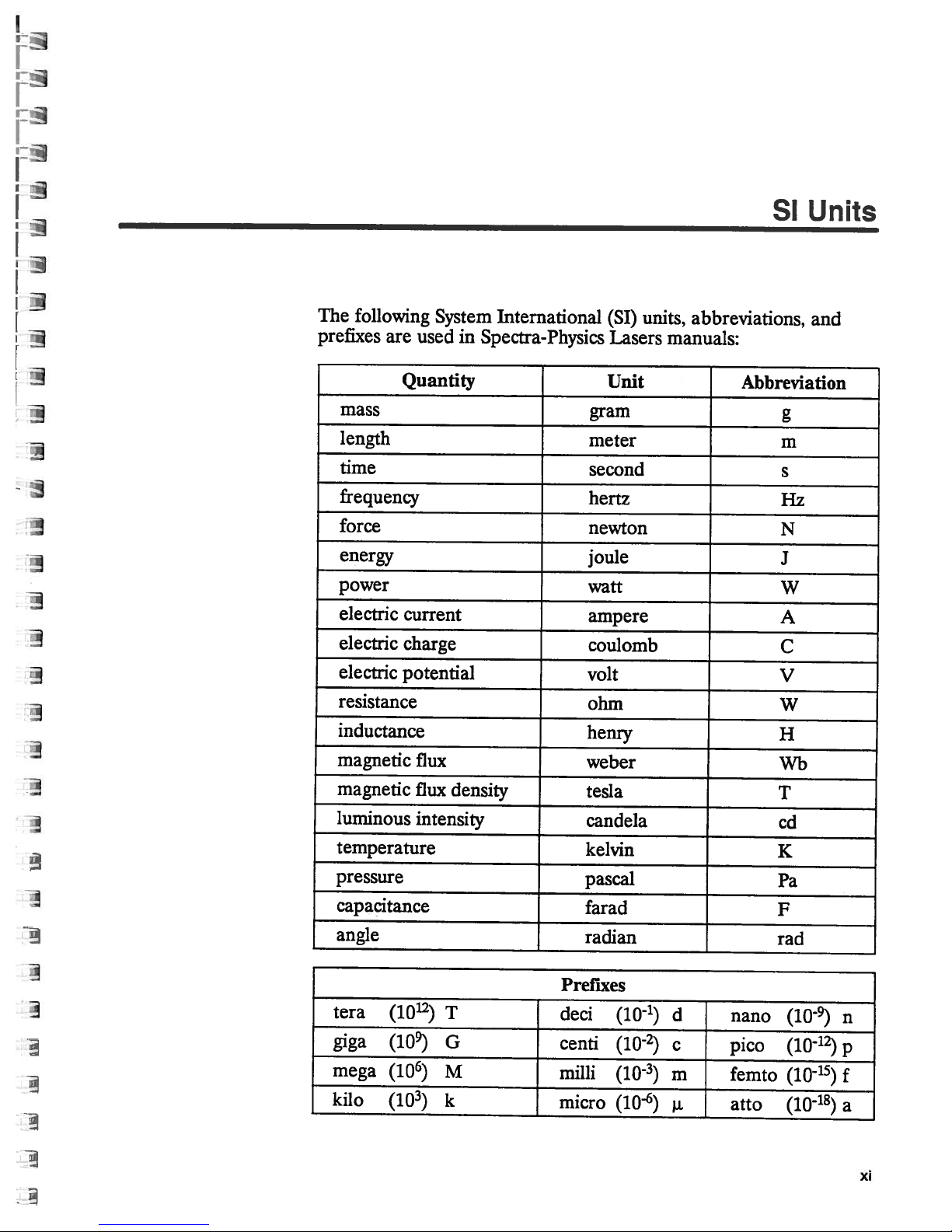
The
following
prefixes
are
System
used
International
in
Spectra-Physics
units,
(SI)
Lasers
abbreviations,
manuals:
SI
Units
and
Quantity
mass
length
time
frequency
force
energy
power
electric
electric
electric
current
charge
potential
resistance
inductance
magnetic
magnetic
luminous
temperature
pressure
capacitance
angle
flux
flux
density
intensity
Unit
gram
meter
second
hertz
newton
joule
watt
ampere
coulomb
volt
ohm
henry
weber
tesla
candela
kelvin
pascal
farad
radian
Abbreviation
g
m
s
Hz
N
J
W
A
C
V
W
H
Wb
T
cd
K
Pa
F
rad
tera
giga
mega
kilo
(1012)
(1O)
(106)
(10)
T
G
M
k
Prefixes
deci
centi
milli
micro
(10-1)
(102)
(10)
(10-6)
d
c
m
nano
pico
femto
atto
(10)
(1012)
(10-15)
(10-18)
n
p
f
a
xi
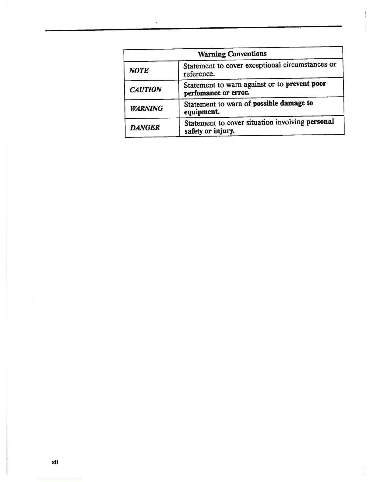
NOTE
CAUTION
WARNING
DANGER
Warning
Statement
reference.
Statement
perfomance
Statement
equipment.
Statement
injury.
safety
or
Conventions
cover
to
warn
to
error.
or
warn
to
cover
to
exceptional
against
of
or
possible
situation
circumstances
prevent
to
damage
involving
or
poor
to
personal
XII

Chapter
1
Introduction
Emission
and
Absorption
Laser
lated
emit
relationship
amplifier
identical
sources.
matic,
Radiant
molecular
structure
nucleus
a
distinct
at
a
teristic
that
all
“p”
lobed
mined
atom—its energy
throughout
levels:
state,
in
its
forces.
Light*
of
is
an
acronym
Emission
light
in
all
with
of
light,
in
phase,
Its
output
and coherent.
emission
structure
describes
with
oneormore
orbital
given
position
shape
thatisdefined
probability,
orbitals
configuration
by
the
orbital
the
the
level
and
higher
ground
state,itwill
derived
of
Radiation.”
directions,
one
another.
and
because
direction,
beam
and
that
is
absorption
of
materials.
an
electrically
represents
relative
all
e.g.,
surround
“s”
the
(Figure
thatitoccupies,
level—depends
available
with
energy
the
orbitals.
lowest
levels
from
Thermal
the
individual
But
its
and
singularly
electrons
the
to
the
by
the radial
orbitals
x,
andzaxes
y,
1—1).
possible
are
stay
there
“Light
Amplification
radiators,
photons
because
output
comprises
amplitude,
directional,
take
place
The
contemporary
neutral
system
bound
probability
nucleus.
and
are
spherically
The
energy
and the
on
the
distribution
Each
atom
energy
called
excited
untilitis
the
laser
itisunique
within
to
it.
Each electron
of
Each
orbital
angular
of
the
of
over-all
has
is
excited
by
Stimu
suchasthe
having
is
an
no
oscillating
photons
among
intense,
the
atomic
model
monochro
of
composed
finding
the
has
dependence of
symmetrical,
nucleus
an
inadouble-
electronisdeter
energy
of
its
electrons
array
an
called
states.
the
If
by
of
an
external
sun,
definite
that
are
light
or
atomic
of
a
occupies
electron
a
charac
and
of
an
energy
ground
atom
is
*
“Light”
infrared
will
be
usedtodescribe
to ultraviolet.
the
portion
of
the electromagnetic
spectrum
from
far
1—1

Quanta-Ray
GCR
Series
x.
x
Figure
the
of
dence
1—1:
probability
orbital
the
of
Movement
when
be
the
caused
transitions
photon
content
energy
levels,
where
of
is
of
i.e.,
h
Likewise,
equal
state,
energy
to
the
hv
probabiit
the
from
atom
by
in
light.
E
1
the
Planck’s
is
when
E2—E1.
atom
and
Electrons
finding
of
being
determined
one
either
collision
directions
both
Consider
higher
a
to
incident
constant,
atom
an
Because
may
frequency
occupy
energy
absorbs
with
a
one
photon
hv=E
2—E1
excited
its
decay
distinct
electron
an
the
by
another—a
to
level
emits
or
electron
free
a
occur
as
transition
energy
with
matches
v
and
E
2
to
tendency
spontaneously,
orbitals
at
radial
energy.
result
a
from
the
the
is
decays
is
given
a
and
Upward
an
or
of
lower
a
It
E2.
energy
[1]
frequency
toward
emitting
[2]
defined
are
that
shape
position,
angular
the
depen
transition—happens
transitions
with
occur
the
energy
and
energy
if
between
photon.
energy
excited
interaction
level
only
will
difference
of
it
E1,
to
lower
the
atom,
whose
loses
photon
a
by
can
a
the
with
1-2
Spontaneous
energy
lost
collision
ulated
shedding
the
with
decay
to
energy
incident
spontaneous
phase
relationship
decay
taking
another
to
one
emission
can
another
E
1
in
the
in
phase,
with
also
form,
atom.
interacting
by
form
frequency,
produces
one
occur
e.g.,
atom
An
pair
of
a
photons
another.
without
transfer
excited
with
of
and
emission
of
to
photon
a
photons
direction.
have
that
of
kinetic
can
E
2
of
that
By
no
photon,
a
energy
be
also
frequency
identical
are
contrast,
directional
the
by
stim
v,
to
or

Introduction
Population
Inversion
laser
A
taneous
conditions
describe
The
tween the
be
both
probability.
to
Moreover,
dent
tion.”
same
depends
andN2
When
of
all
frequencies
any
is
and
these
absorption
shown
number
the
the population
wave
It
can
regardless
only
,
and
material
a
its
atoms
atoms
frequency
designed
stimulated
favorable
conditions.
coefficient
rates
of
that
the
Similarly,
the
transition
and
a
also
of
on
flux
the
over
in
ground
the
exceeds
positive.
is
take
to
to
emission
rate
of
atoms
of the
characteristic
be
shown
direction.
the
difference
of
isatthermal
the array
that
advantage
emission
light
at
of excitation
in
the
rate
upper
probability
that
incident
the
of
state.
of
of
phenomena,
amplification.
given
a
and
the
of
level
of
Therefore,
between
equilibrium,
available
Since
emission,
frequency
absorption
from
lower
stimulated
(N2)
depends
transition
the
the
transition
wave.
energy
the
the
absorption,
using
The
at that
E
1
to
(N1)
level
emission
the
and
on
cross
absorption
the
the
populations
a
Boltzmann
levels
rate
of
absorption
and
them
following
is
E
2
called
difference
the
frequency.
is
proportional
and
the
is
transition
the
flux
its
section
exists
absorption
coefficient
both
spon
create
to
paragraphs
be
can
It
transition
proportional
probability.
is
of
inci
sec
the
nearly
all
at
of the
“cross
coefficient
involved,
distribution
with
to
N
1
If
enough
shifted
and
frequency
levels,
equality;
sition
However,
relationship
excitation
A
(a).
toE4.If
E1,
E3.
lifetime,
from
ton of
to
ing
kept
inversion
coefficient
through
greater
untilN2
stimulated
it
is
is
matched
model
A
photon
theE4
and
if
IfE3
the
above.
frequency.
the
ground
the
rate
large
the
the
that
four-level
is
between
light
of
frequency
=
N1.
emission
v
is
zero.
If
impossible
is,N2
if
three
satisfies
can
of
E
4
is
metastable,
population
TheE3
state,
of
and
atv2becomes
material,
population
can
by
or
certain
create
laser
frequency
E
3
to
unstable,
atom
Finally,
E1,
absorption
that
of
E
3
v
Under
the transition
to
one
more
a
transition
E
2
and
which
these
are
equal,
drive
never
in
the opposite
energy
requirements
population
transition
v1
excites—or
the
atom
i.e.,
atoms
will
grow
will
eventually
ifE2
keeping
of
v2
.
remains
E2.
Under
negative.
is
now
inversion,
is
supplied,
conditions
and
scheme
the populations
exceed
levels
inversion,
scheme
probability
will
that
rapidly
is
unstable,
the
population
In
this
low,
these
Lightisamplified
called
the
the
the
because
N
1
direction.
are
described
“pumps”—an
is
decay
occupy
as
decay
its
way
thus
establishing
conditions,
an “active
greater
populations
the
rates of
absorption
is
limited
involved
every
employed,
below,
in
which
is
depicted
greater
almost
it
excited
atoms
the
the
immediately
have
atoms
toE2,emitting
will
of
E
2
population
as
medium.”
gain.
absorption
coefficient
two
to
beyond
upward
andiftheir
additional
N2>
in
Figure
atom
than
thatofE
a
relatively
cascade
rapidly
small
of
a
population
the
absorption
it
passes
can
N1.
and
be
energy
tran
from
to
long
a
pho
return
reduc
E3is
The
at
1—2
E
1
4
to
1-3
Quanta-Ray
GCR
Series
cm
1
E
3
E
2
I9/2
11502
2111
Nd
ctrf
1
3
+
Nd:YAG
as
Excitation
an
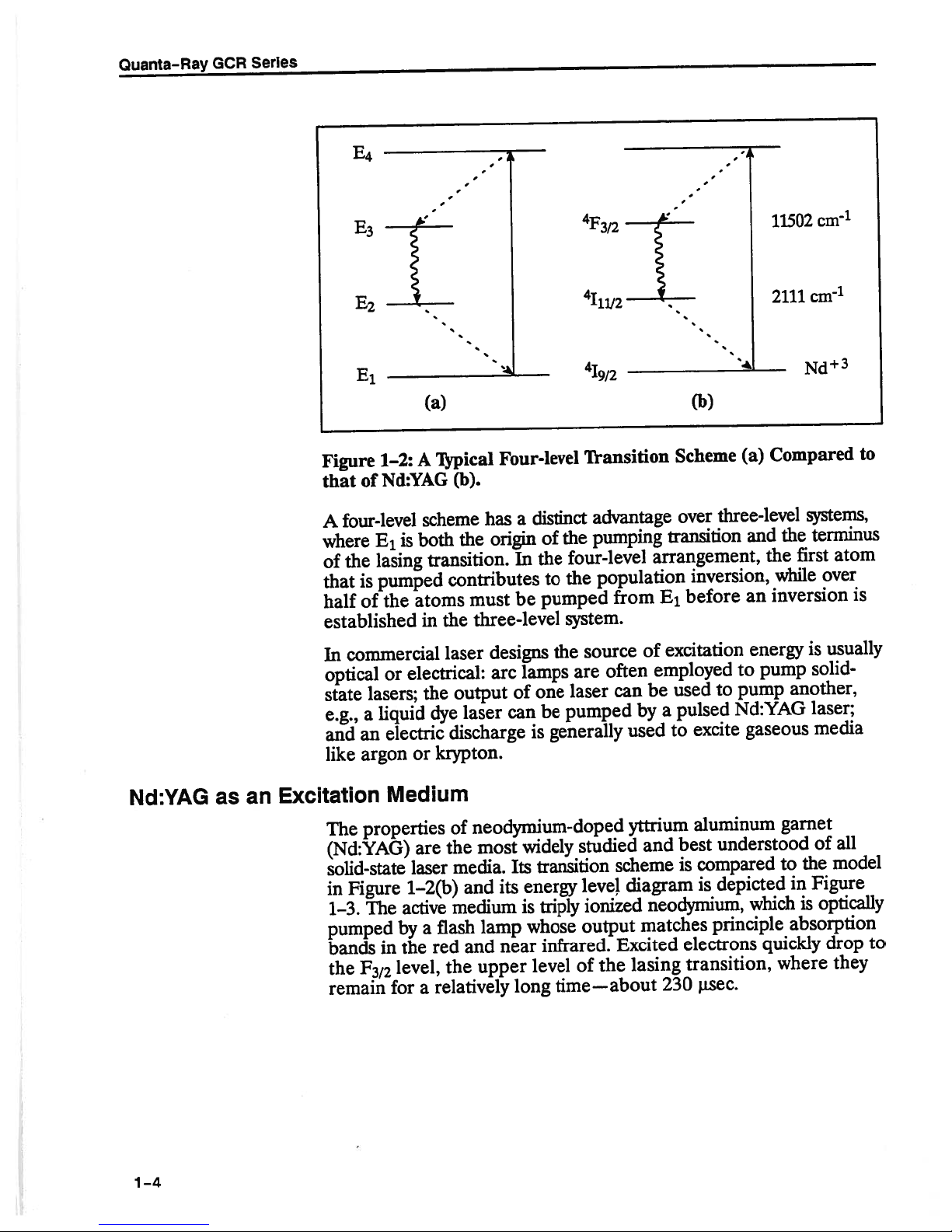
Figure
that
A
where
of
that
half
1—2:
Nd:YAG
of
four-level
E
1
lasing
the
pumped
is
the
of
established
commercial
In
optical
state
e.g.,
and
like
or
lasers;
liquid
a
electric
an
argon
Medium
properties
The
(Nd:YAG)
solid-state
Figure
in
The
1-3.
pumped
F
372
in
for
bands
the
remain
(a)
Typical
A
scheme
is
both
transition.
atoms
the
in
laser
electrical:
the
dye
or
krypton.
are
laser
1—2(b)
active
flash
by
a
the
red
level,
the
relatively
a
Four-level
(b).
distinct
a
has
In
be
of
the
to
pumped
origin
the
contributes
must
three-level
designs
lamps
arc
one
output
laser
discharge
of
the
media.
and
medium
and
of
be
can
generally
is
neodymium-doped
widely
most
transition
Its
energy
its
triply
is
whose
lamp
infrared.
near
upper
level
long
Transition
advantage
pumping
the
four-level
population
the
from
system.
source
the
often
are
can
laser
pumped
used
yttrium
studied
scheme
diagram
IeveJ
ionized
output
Excited
the
of
lasing
time—about
(b)
Scheme
over
transition
arrangement,
inversion,
E1before
excitation
of
employed
used
be
pulsed
a
by
excite
to
aluminum
best
and
compared
is
is
neodymium,
matches
electrons
transition,
230
lisec.
Compared
(a)
three-level
and
the
while
inversion
an
energy
to
pump
pump
to
Nd:YAG
gaseous
understood
depicted
which
principle
quickly
where
systems,
terminus
the
atom
first
over
usually
is
solid-
another,
laser;
media
garnet
all
of
model
the
to
Figure
in
is
optically
absorption
drop
they
to
is
to
1-4
Introduction
—
20
FZ
Pump
Bands
18
16
-
_—
11502
cmR2
11414
R
1
Transition
cm
1
6000
“4000
cm
2473
I15/2,
113/2,:
111/2
-‘:_______
%/2
---_____
,:-
—------.
Laser
—2526
—---—--
.-.-.-.-
14
-
E
12-
C.)
Laser
10
8-
6-
4.
2-
-
115/2
13/2
Transition
--- -
--
-.
-
__4
-.
- -
-
-
- -
-
- -
0-
Ground
Level
311
134
\
0
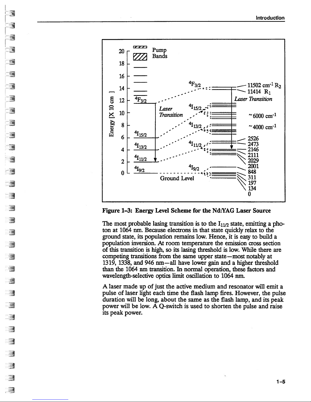
Figure
most
The
ton
at
ground
population
of
this
competing
1319,
than
1338,
the
Energy
1—3:
probable
1064
nm.
Because
its
state,
population
inversion.Atroom
transitionishigh,
transitions
and
946
1064
nm
transition.
wavelength-selective
A laser
pulse
duration
power
its
peak
made
of laser
willbelong,
will
be
power.
upofjust
light each
low.
Level
lasing
Scheme
transition
electronsinthat
remains
its
so
from
the
nm—all
optics
limit
the
time
about
A
Q-switch
for
the
is
to the
low.
Hence, itiseasytobuild
temperature
lasing
have lower
In
same
normal
threshold
upper
gain
operation,
oscillationto1064
active
the
medium and
the
flash
sameasthe
is
used
lamp
to
Nd:YAG
‘1i12
state
the
Laser
state,
quickly
emission
is
low.
Source
emitting
relax
cross
While
state—most notably
and
higher
a
these
factors
nm.
resonator
fires.
However,
flash
shorten
lamp,
the
and
pulse
pho
a
to
the
a
section
there
are
at
threshold
and
will
emit
the
pulse
its
peak
and
raise
a
1—5
Quanta-Ray
0-switching
GCR
Series
Because
population
much
while
quickly
as
the
released,
upper
the
excited
of
capacitor
a
population
level
the
stores
inversion
laser
transition
the
of
neodymium
electrical
builds,
emit
will
ions
energy.
short
a
can
and
has
build
If
if
pulse
the
lifetime,
long
a
in
up
oscillation
stored
high
of
the
YAG
prevented
be
energy
intensity
a
large
rod,
can
light.
be
electro-optic
An
cillation.
quarter-wave
a
the
istics,
closed
As
Pockels
which
(high
ctor
Quarter-Wave
Plate
Figure
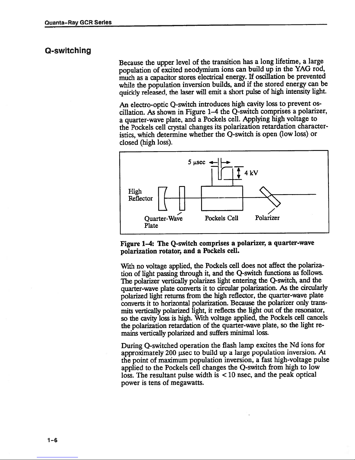
1—4:
polarization
With
tion
The
voltage
no
light
of
polarizer
quarter-wave
polarized
converts
mits
the
so
the
mains
light
it
vertically
cavity
polarization
vertically
0-switch
shown
plate,
cell
crystal
determine
loss).
Q-switch
The
rotator,
applied,
passing
vertically
plate
returns
horizontal
to
polarized
is
loss
retardation
polarized
Figure
in
and
changes
whether
sec
5
and
the
through
polarizes
converts
from
polarization.
light,
With
high.
introduces
1—4
Pockels
a
its
the
Pockels
comprises
Pockels
a
Pockels
it,
and
light
circular
to
it
high
the
it
reflects
voltage
the
of
suffers
and
cavity
high
Q-switch
the
Applying
cell.
polarization
0-switch
—
—i’
Cell
polarizer,
a
cell.
does
cell
Q-switch
the
entering
polarization.
reflector,
Because
light
the
applied,
quarter-wave
minimal
loss
comprises
high
retardation
open
is
Polarizer
a
quarter-wave
not
affect
functions
the
Q-switch,
quarter-wave
the
polarizer
the
outofthe
Pockels
the
plate,
loss.
prevent
to
voltage
(low
the
As
so
polarizer,
a
character
loss)
polariza
follows.
as
and
circularly
the
only
resonator,
cancels
cell
light
the
Os
to
or
the
plate
trans
re
1—6
During
0-switched
approximately
the
point
applied
loss.
power
of
the
to
resultant
The
is
tensofmegawatts.
operation
jisec
200
maximum
Pockels
pulse
the
build
to
population
changes
cell
width
is
flash
a
large
up
inversion,
the
nsec,
<10
lamp
excites
population
a
0-switch
and
the
fast
high-voltage
from
peak
the
ions
Nd
inversion.
pulse
hightolow
optical
for
At

Introduction
Resonant
Optical
This
short
the
pulsed
conversion
doubling,
conversion.
fast
phenomena
An
alternative
GCR.
fires,
result
Voltage
and
is
between
pulse
train
pulse
mode
ments
where
critical
Cavity
A
resonant
the
cavity
active
and
to
the
Stimulated
direction
eight,
equilibrium
pulse
Nd:YAG
through
frequency
A short
the
Q-switch
train
a
individual
similar
is
allows
total
factor.
cavity,
medium.
are
reflected,
emission
from
the
between
of
high
laser.
several
mixing,
pulse
like
“long
is
applied
of
pulses
pulsesof2
to
safer
pulse
which
produces
interaction.
each
numbers
peak
Its
nonlinear
provides
pulse”
to
held
is
chemical
mode
the
rapid
about
that
of
alignment
energy,
is
defined
Photons
returning
continue
excitation
power
high
dye
Pockels
open
200
to
a
single
emitted
two
The
to
and
peak
laser
excellent
reactions
of
for
i.zsec
4
isec.
and
its
not
by
interact
to
photons
two
increase
emission
is
the
key
power
processes,
pumping,
operation
cell
as
entire
the
long,
The
Q-switched
set-up,
distribution
mirrors,
two
parallel
with
of
become
geometrically
is
to
the usefulness
permits
e.g.,
or
Raman
temporal
or
high-speed
is
built
soon
lamp
with
a
energy
total
pulse.
and
is
useful
in
provides
the
to
other
equal
energy,
four,
reached.
wavelength
frequency
frequency
resolution
in
to
the
flash
as
firing.
separation
of
This
in
time,
feedback
optical
excited
phase
four
become
until
of
motion.
the
lamp
The
the
long
experi
the
is
axis
of
ions.
an
of
and
Both
mirrors
interest
while
are
transmitting
coupler—transmits
the
escaping
There
(Figure
ray
of
light
the
stable
cavity
laser.
mirrors,
By
reflected
Figure
are
1—5:
radiation
two
1—5).
traveling
resonator
contrast,
away
Stable
major
The
so
from
coated
fraction
a
becomes
types
difference
close
the
ray
it
is
always
a
ray
travellinginan
the
axis
and
Unstable
reflect
to
all
others.
of
the
the
of
optical
between
to,
and
parallel
is
reflected
contained along
one
by
Stabl
Unstable
Resonator
wavelength,
the
One
energy
output
resonators:
them
toward
unstable
of
the
or
of the
beam
stored
mirrors—the
in
of
the
stable
in
lies
with
the
the
the
what
optical
optical
primary
resonator
cavity
mirrors.
Configurations
wavelengths,
output
the
cavity,
laser.
and
unstable
happens
axis.
axis
by
axis
of
can
be
and
to
In
of
a
its
the
1—7
Quanta—Ray
GCR
Series
Stable
the
put.
Thus,
resonators
optical
axis
Conversely,
can
they
cross-sectional
In
the
coupler
the
and
resonator
output
The
forms.
substrate
escapes
“diffraction
partially
(an
a
The
is
replaced
RVR
employs
substrate.
reflector
tivity
near-gaussian
sian
coupled
If
Nd:YAG
at
to
formance,
rod,
energy
the
focus
one
reflected
be
Uniform
Nd:YAG
length
focal
which
the
of
be
rod
carefully
rod
cooling
lasers.
depends
the
must
also
controlled
can
of
the
unstable
efficiently
is
area
in
case,
first
placed
coupled
reflective
is
third
by
optic).
spatial
resonator”
the
be
elliptical
an
output
of
must
of
through
is
also
When
reflector
high
remain
causes
extract
only
resonator,
resonators
extract
large,
an
unstable
small
a
the
on
diffracting
by
resonator”
variation
a
a
partial
reflector
This
profile
at
(OCR)
beam
uniformly
chamber
the
rod,
essential
heated,
average
the
on
must
stable
radially
a
the
for
energy
which
can
energy
of
that
like
resonator
reflector
high
optical
axis
around
(DCR)
on
that
the
coating
reflector
is
capable
the laser
name.
its
is
to
illuminated.
causes
whichisplaced
optimal
to
Nd:YAG
the
power
matched
be
during
operation.
variable
beam
best
from
have
from
the
large
active
limits
typical
can
is
the
of
this
name.
its
uniformly
where
first,
radially
with
of
output,
be
uniformly
Placing
all
performance
rod
absorbed.
to
polarization
quality.
small
volume
a
energyofthe
beam
media
Nd:YAG
one
take
mounted
resonator.
which
dot,
second
A
covers
the
variable
producing
gives
and
distributed,
the
the
light
the
at
other
of
becomes
For
focal
the
The
thermal
rotation
diameters.
whose
rods.
laser
three
of
a
clear
on
Energy
gives
form
the
small
reflec
gaussian
the
“gaus
lamp
flash
produces
it
focus.
pulsed
lens
a
optimal
length
gradient
that
near
out
the
whole
high
or
the
whose
per
of
the
must
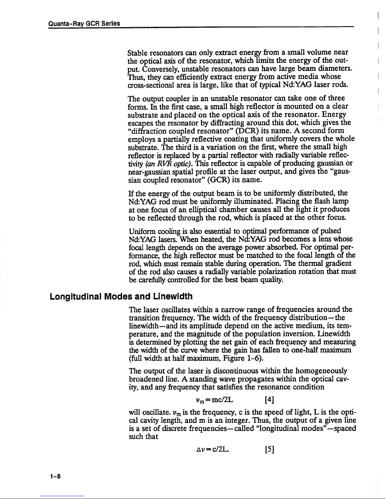
Longitudinal
1—8
Modes
Linewidth
and
oscillates
laser
The
transition
frequency.
Iinewidth—and
perature,
determined
is
the
width
(full
The
broadened
ity,
and
will
cal
cavity
a
is
set
such
and
of
width
at
output
any
oscillate.
length,
discrete
of
that
the
of
line.
frequency
within
The
its
amplitude
the
magnitude
by
half
the
plotting
curve
A
maximum,
laser
standing
the
where
is
that
=
Vm
frequency,
the
is
Vm
is
m
and
frequencies—called
zv=c/2L.
of
range
the
a
narrow
width
depend
of
net
the
Figure
population
the
gain
gain
1—6).
discontinuous
propagates
wave
satisfies
the
mc/2L
is
c
an
integer.
of frequencies
frequency
the
active
on
inversion.
of
has
frequency
each
fallentoone-half
within
the
within
resonance
[4]
the
of
output
the
Thus,
speed
“longitudinal
[51
around
distribution—the
medium,
its
Linewidth
measuring
and
maximum
homogeneously
the
optical
cav
condition
light,
Listhe
of
a
given
modes”—spaced
the
tem
opti
line
Introduction
I
Figure
Single
An
in
an
1—6:
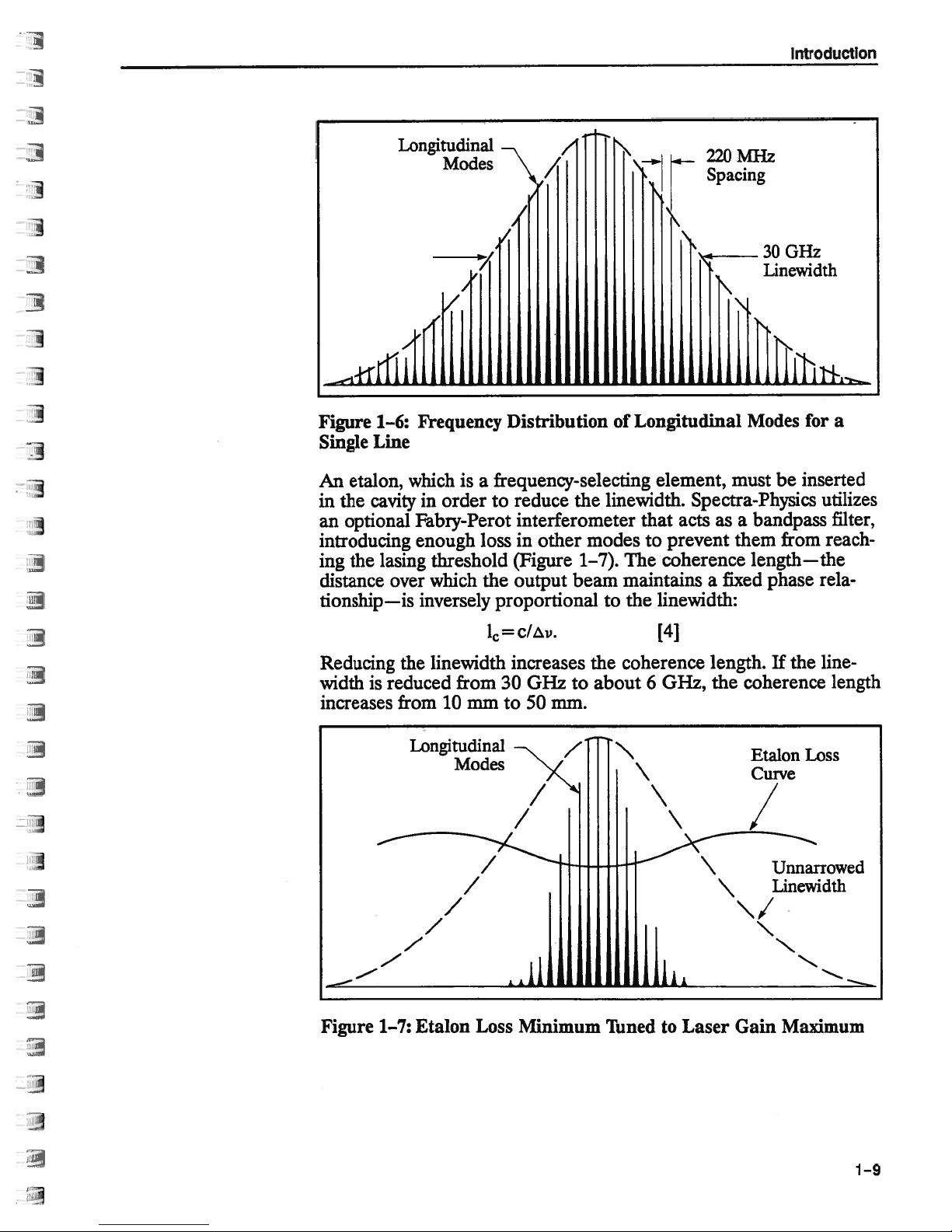
Line
etalon,
cavity
the
optional
introducing
lasing
the
ing
distance
over
tionship—is
Longitudinal
Modes
Frequency
which
in
is
order
Fabry-Perot
enough
threshold
which
inversely
/
/
-/
I
/
Distribution
frequency-selecting
a
to
reduce
the
interferometer
in
loss
(Figure
output beam
the
other
modes
1—7).
proportional
Longitudinal
of
element,
linewidth.
that
to
The
coherence
maintains
the
to
linewidth:
MHz
220
Spacing
Modes
must be
Spectra-Physics
asabandpass
acts
prevent
them
length—the
fixed
a
30GHz
Linewidth
for
inserted
utilizes
reach
from
phase
rela
a
filter,
Reducing
width
is
increases
Figure
the
reduced
from
Longitudinal
Etalon
1—7:
1=
linewidth
from
10
mm
Modes
Loss
c/v.
increases
0Hz
30
to
50
Minimum
to
mm.
z
coherence
the
about
Tuned
\
6
[4]
0Hz,
to
length.
Laser
the
coherence
Gain
If
Etalon
Curve
Maximum
the
line-
length
Loss
1—9
Quanta-Ray
GCR
Series
Producing
Other
Wavelengths
peak
high
The
nonlinear
version
(KD*p).
interacts
fundamental
For
and
tion
wavelength
their
gating
length
propagate
most
Phase
crystal
axes
With
matching,
larized
wavelength
an
put
wavelength
matching
in
efficiency.
the
may
in
In
with
maximum
phase
most
of
index
waves.
matches
efficient
matching
and
the
of
KD*P
along
angle
between
remains
K1)*P
residual
yield
can
Type
power
simplest
the
crystal
the
wavelength.
efficiency
relationship
materials
longer.
gets
refraction
of
these
In
extraordinary
the
in
phase
and
under
critically
is
angle
the
crystal.
phase
two
input
the
extraordinary
the
linearly
the
polarized
elliptically
is
used
be
more
is
II
However,
nm
1064
better
overall
the
of
crystals
Q-switched
like
case
produce
to
waves
the
throughout
depends
However,
depends
materials,
the
at
“phase
these
dependent
between
matching
is
along
the
polarized.
extraordinary
along
the
polarized.
generate
to
widely
light
experiments
for
some
system
potassium
1064
the
secondary
a
must
crystal.
the
wavelength,
the
on
some
the
on
the
if
index
speed.
same
matching”
direction
the
alternatives
ordinary
This
axis.
In
Type
and
extraordinary
Although
second
the
because
used
highest
efficiency,
performance.
pulses
permit
dideuterium
Nd:YAG
nm
maintain
The
materials
polarization
ordinary
the
of
other,
Frequency
conditions.
temperature
the
on
polarization
of
exist.
and
axis,
leaves
the
input
LI
ordinary
axis.
either
harmonic
of
require
frequency
fundamental
with
wave
the
same
index
decreasing
birefringent:
are
of
index
of
the
conversion
In
Type
the
the
residual
polarization
axes,
residual
The
type
higher
its
and
Type
polarization
linear
phosphate
half
speed
refrac
of
propa
the
wave
one
waves
the
of
and
phase
I
output
input
phase
of
Nd:YAG
of
the
while
conversion
doubling
I
con
the
as
the
po
is
is
input
the
is
at
out
of
1—10
resultant
The
through
mixed
355
in
nm
—cover
ultraviolet,
the
and
532
and
355
studies
optical
These
of
modification
fixed
shifting
continuously
is
532
second
a
KD*P
wave.
the
with
These
electromagnetic
which
will
nm
355
266
nm
many
molecules.
frequencies
by
using
or
tunable
wave
nm
crystal,
the
four
enhances
pump
useful
are
of
them
be
can
which
residual
yields
1064
wavelengths—
spectrum
the
lasers
dye
for
dissociation
nm
1064
extended
be
pump
over
and
materials
can
to
output
doubled
266
a
nm
1064,
from
usefulness
with
266
and
probing
further
laser.
dye
a
wide
a
nm
by
wave.
again
fundamental
355,
532,
the
near
of
the
conversion
high
and
photodestructive
are
nm
of
semiconductors.
through
result
The
of
range
wavelengths.
passing
It
can
produce
to
and
infrared
Nd:YAG
efficiency.
widely
Raman
of
it
also
266
laser.
used
the
be
a
nm
to
for
latter
Introduction
Resonator
Structural
Considerations
The
stability
the
resonator
several
cause
length
where
the
eliminate
The
The
high
a
the
Graphite
have
structural
compensation
The
expansion
over
sources
corresponding
changes
is
L
the
resonator
frequency
choice
ideal
material
ability
length
negative
a
the
wide
lowest
of
composite,
material.
of
of
the
structure.
including
due
cavity
structure
of
materials
to
distribute
the
structure.
thermal
system
expansion
the
metal
range
oscillating
Small
temperature
changes
to
temperature
L=
length,
and
drift,
either
affects
has
both
heat
such
as
expansion
Since
of
its
of
the
of
parts,
temperatures.
frequency
changes
in
the
oLT
cisthe
T
is
c
the
low
a
evenly,
that
used
coefficient
resonator
the
graphite
so
the
depends
in
cavity
changes
resonant
can
be
expressed
[5]
thermal
temperature
or
T
must
length
thermal
coefficient
net
stability
expansion
causing
in
the
is
also
structure
rods
change
on
length,
and
mechanical
frequency.
expansion
change.
zero.
be
of
constant
a
OCR
offsets
series
of
any
negative,
can
be
the
remains
the
design
which
Cavity
as
coefficient
In
order
the
structure.
coefficient
zT
resonators,
currently
the
thermal
kept
simple.
positive
near
of
have
shifts,
of
to
and
along
used
zero
Frequency
resonator
movement
resonator
the
case
stability
structure.
of
cavity
structure
that
surrounds
also
depends
Modulation
mirrors,
or
acoustic
the
laser
can
on
due
be
noise.
helps
the
mechanical
“jitter,”
to
caused
Isolation
reduce
by
jitter.
rigidity
the
microphonic
external
the
of
of
shock
resonator
to
the
the
from
1—11
Quanta—Ray
Pulse
Triggering
GCR
Series
Sequence
and
__rn__
Timing
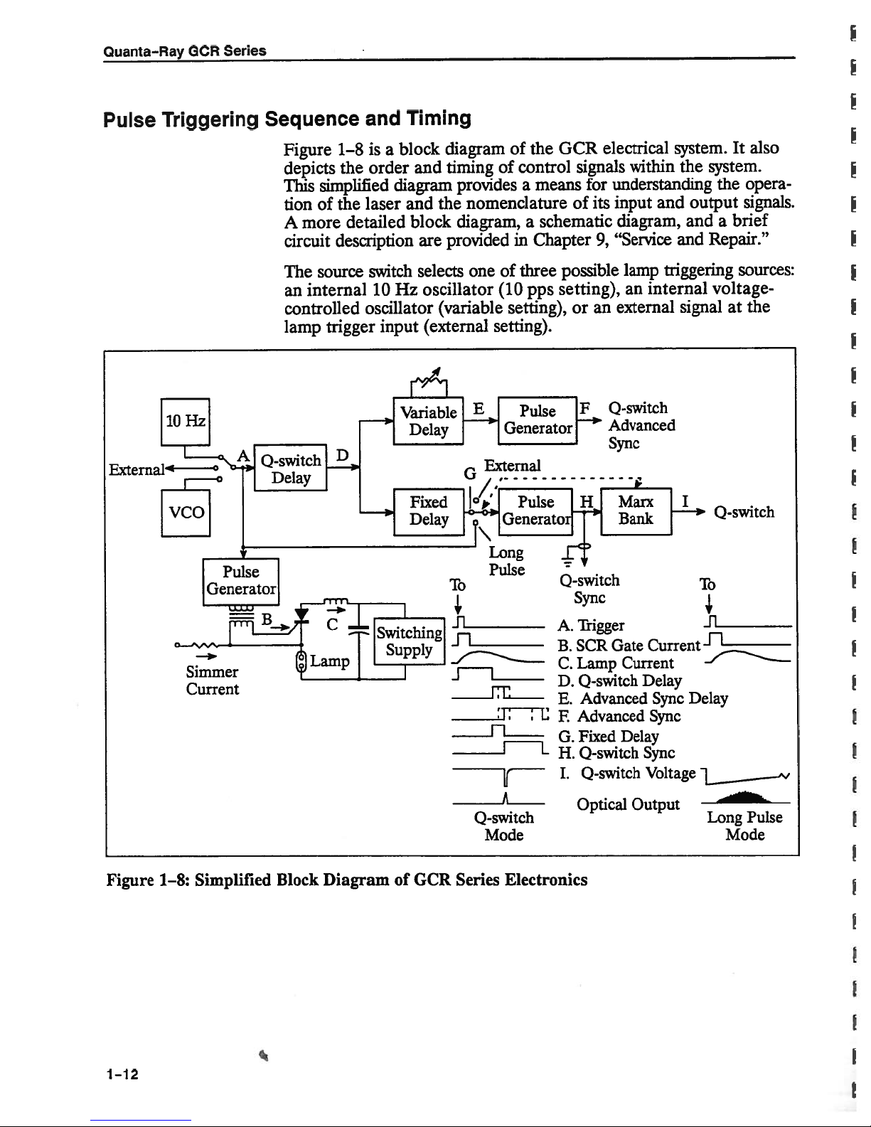
Figure
depicts
This
tion
A
circuit
The
an
controlled
lamp
1—8isa
the
simplified
the
of
more
description
source
internal
trigger
order
laser
detailed
switch
10
oscillator
input
block
and
diagram
the
and
block
are
selects
oscillator
Hz
(variable
(external
diagram
timing
provided
of control
provides
nomenclature
diagram,
one
of
(10
setting).
of
the
means
a
schematic
a
in
Chapter
three
pps
setting),
GCR
signals
for
of
its
9,
possible
setting),
or
an
electrical
within
understanding
input
diagram,
“Service
lamp
an
external
Advanced
Sync
system.
and
triggering
internal
It
the
system.
opera
the
output
and
and
signalatthe
signals.
brief
a
Repair.”
sources:
voltage-
0-switch
also
Figure
Simmer
Current
1—8:
Simplified
Block
Diagram
of
GCR
To
Ji
11
JL
Series
Pulse
A
0-switch
Mode
Electronics
0-switch
Sync
Trigger
A.
SCR
B.
Lamp
C.
D.
0-switch
Advanced
E.
Advanced
F
Fixed
G.
H.
0-switch
I.
0-switch
Optical
Gate
Current
Delay
Output
Current
Delay
Sync
Sync
Sync
Voltage
To
.fl_________
Delay
Long
Pulse
Mode
.4
1—12
Introduction
signal
This
the
fires
and
the
forming
pulse
rent
ingofthe
Nd:YAG
the
0
Pockels
mode
The
Pockels
triggering
long
pulse
system
In
the normal
(A)
SCR
0-switch
network,
(C)
Q-switch
rod.
of
the
cell.
switch
cell
pulseatthe
mode
alignment.
Subsequently,
nal
voltage
dation
total
The
delay
triggering
and
output
characteristic
delayofD
Q-switch
Signal
(D).
andavariable
The
variable
after
the
or
follows
end
the
advanced
the
post-trigger
the trigger
is
gate
delay.
whose
through
After
cavity
selects
be fired
can
that
mode,
the
the
of
+0.
advanced
D
delay
delay
of
the
sync
opening
pulse
current
generator
The
discharge
lamp.
the
until
the
approximately
to
maximum
the
internally
0-switch
provides
the
0-switch
pulse
generator
electro-optic
the
Marx
the
of
bank
Pockels
sync
triggers
(E),
pulse
fixed
pulse
with
both
setting
adjustable,
is
delay pulse.
generator
of
the
range
a
for
source
all
for
current
gate
SCR
produces
Q-switch
The
population
225
jisec,
applying
by
configuration
(normal
trigger
pulseoflow
a
input (external
delay
fired
is
driver
(I)
changes
cell,
is
up
the
also
fixed
race
a
signal
soitcan
The
(F),
whose
0-switch
of
(I).
±500
subsequent
the
pulse
(B)
a
critically
delay
inversion
its
high
of
the
mode),
peak
firesafixed
(D)
providing
(H),
(Marx
the
opening
derived
delay
between
variable
output
This
nsec.
functions.
forming network
the
fires
pulse
damped
prevents
built
has
output
voltage
0-switch.
up
(D)
increases
(I)tothe
The
externally
mode),
power
useful
delay
sync
a
bank).
The
polarization
the
0-switch
the
from
(G)
these
end
either
delay
creates
described
either
two
before
pulse
pre-
a
0-switch
precedes
It
cur
open
the
in
a
by
orina
for
(0).
sig
high
retar
after
above
pulses.
triggers
or
a
or
In
the
firing.
lamp
pulse
that
inhibited
long
pulse
It
yields
this
in
mode
is
internally
long
a
mode.
the
Pockels
charged
optical
cell
to
pulse.
triggered
is
provide
The
0-switch
a
4
long,
at
sync
the
high
moment
voltage
output
of
is
1-13
Quanta—Ray
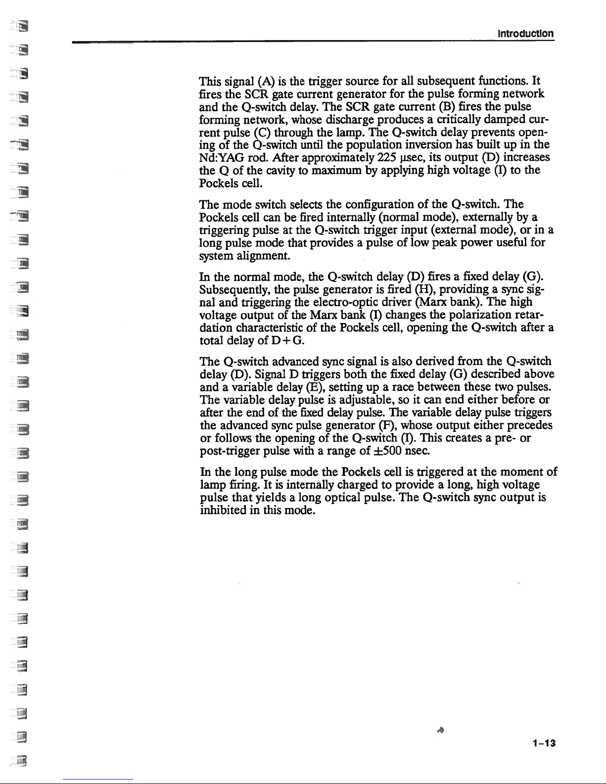
Specifications
1’2
GCR
Series
Spatial
Near
Field
Far
Maximum
Output
1064nm
532nm
355nm
266nm
Repetition
Optimum
Range
Diameter
Rod
All
specflcations
1.
operation
Near
2.
90%
profiles
Refers
3.
points.
Harmonic
4.
II
second
energies
Actual
5.
Profile
2
Field
Energy
as
field
refer
are
the
to
hannonic
can
beam
Model
1
(1
m)
(cc)
Deviation
3
(mJ)
4
Frequency
(mm)’
subject
1(364
nm
profiles
spatial
to
the
correlation
measured
maximwn
energies
are
generation
specfled
be
diameter
(Hz)
change
to
a
standard
with
measured1mfrom
between
focal
vary
plane
from
after
(SHG).
Type
from
at
the
deviation
spec(fIed
when
will
GCR-12
s{N
70%
95%
40%
350
155
70
40
10
2—14
8.5
without
notice.
(nominal8ns)
actual
the
of
a1mfocal
best-fit
the
separation
nm
355
is
I
SHG
diameter
rod
90%
95%
15%
275
115
40
30
10
2—14
8.5
Unless
using
laser
beam
Gaussian
using
energies
used.
depending
pulse
profile
length
dichroic
are
70%
95%
otherwise
width.
a
GCR-14
S
40%
425
180
85
50
10
2—14
8.5
commercially
and
lens.
profile
spec
on
9O%
95%
15%
300
125
45
35
2—14
8.5
specified,
the
best
measured
mirror
jfied
using
configuration.
laser
N
10
70%
95%
40%
675
330
170
2—14
specifications
available
least-squares
in
the
532
pairs.
Type
II
GCR-16
S(N
90%
95%
15%
80
10
2—14
8.5
diagnostic
beam
fit
Gaussian
field
near
energies
nm
A
SHG.
500
215
100
55
10
8.5
are
10%
given
(1
m)
are
increase
GCR-18
SjN
70%
95%
40%
850
425
185
90
10
2—14
8.5
for
Q-switched
system.
profile.
between
specified
in
90%
95%
70%
Far
the
using
355
15%
600
260
120
65
10
2—14
8.5
and
field
FWHM
Type
nm
given
Note:
term
performance
all
appropriate
installation
demonstrated
dependingonthe complexity
Losers
1-14
specifications
These
operation.
representative
Due
energy
each
of
either
parametersatthe
are
to
complexity
the
measurements
width
Pulse
laser.
at
customer
the
the
of
her
for
fun
good
in
involved
customer
and
that
single
and
oratthe
site
measurement
details.
faith
in
site.
copies
are
and
measuring
We
mode
Quanta-Ray
will
of
will
our
be
set
ensure
final
operation
added
levels
that
beam
can
the
to
of
that
the
all
also
sales
energy
profiles
at
many
test
manufacturing
manufacturability
ensure
individual
specifications
and
demonstrated.
be
facility.
price.
Please
and
allow
specflcations,wecannot
burn
A
are
patterns
All
varying
contact
other
range
your
maldng
met
by
included
are
specflcations
additional
of
local
reliable
demonstrate
Spectra-Physics
the
with
long
the
can
be
charges
X
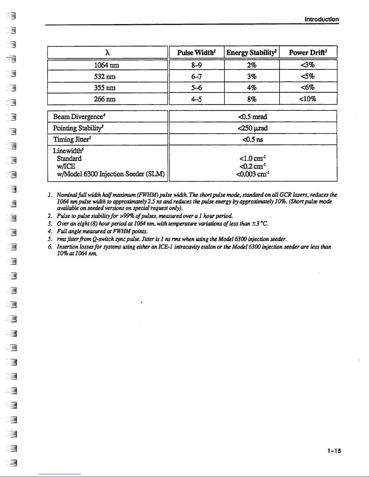
1064nm
Pulse
Width
1
8-9
Energy
Stability
2
2%
{
Power
<3%
Introduction
Drift
3
Beam
Pointing
Timing
Linewidth
6
Standard
w/ICE
w/Model
1.
Nominalfull
1064
available
Pulse
2.
Over
3.
4.
Full
nnsfltterfrom
5.
Insertion
6.
10%
Divergence
4
Stability
3
Jitter
5
6300
width
urn
pulse
width
on
seeded
pulse
eight
(8)
measured
losses
nm.
stabilizyfor
Q-,switch
to
an
angle
at1064
532nm
355nm
266nm
Injection
half
to
versions
hour
at
for
systems
Seeder
on
>99%
at
pulse.
using
(FWHM)
special
of
1064
points.
either
maximum
approximately
period
FWHM
rync
(SLM)
2Susand
request
pulses,
nrn,
Jitter
an
pulse
only).
measured
with
temperature
is
1
ns
ICE-i
6—7
5—6
4-5
width.
The
reduces
over
when
rms
intracavity
short
the
pulse
1
hour
a
variations
using
the
etalonorthe
pulse
energy
period.
Model
mode,
less
of
<250
<0.003
by
6300
Model
3%
4%
8%
mrad
<0.5
I.Lrad
ns
<0.5
<1.Ocnr’
cm-
1
<0.2
cm’
standard
approximately
than
on
±3°C.
injection
6300 injection
GCR
all
10%.
seeder.
lasers,
(Short
seeder
<5%
<6%
<10%
reduces
pulse
are
less
the
mode
than
1-15
Quanta-Ray
GCR
Series
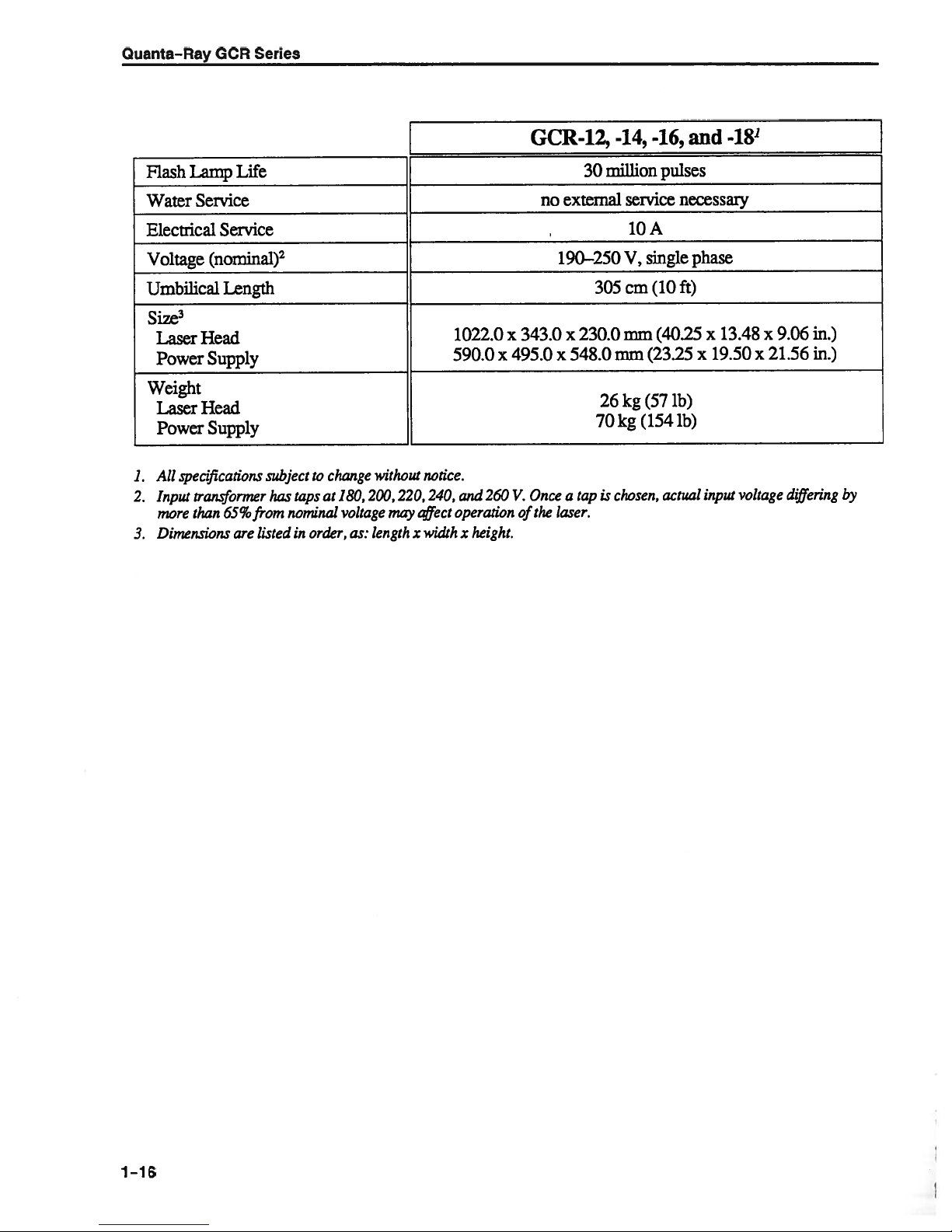
GCR-12,_-14,
-16,
and
-18
Flash
Water
Electrical
Voltage
Umbilical
Size
3
Laser
Power
Weight
Laser
Power
All
specflcations
1.
2.
Input
more
Dimensions
3.
Lamp
Life
Service
Service
(nominal)
2
Length
Head
Supply
Head
Supply
transformer
than
65%
are
subject
has
from
listed
to
change
taps
at
nominal
order,
in
may
notice.
t’4ject
width
x
without
180,200,220,240,
voltage
length
as:
1022.0
x
590.0
260
and
operation
x
height.
no external
x
343.0
495.0
Once
V.
the
of
million
30
190—250
305
x
230.0
x
548.0mm
26
70
tap
is
a
laser.
chosen,
service
10
single
V,
cm
mm
(23.25
kg
(57
(154
kg
pulses
necessary
A
(10
ft)
(40.25
ib)
ib)
actual
phase
x
13.48
19.50
x
input
x
21.56
x
voltage
9.06
differing
in.)
in.)
by
1-16
Chapter
2
Laser
Safety
Precautions
of
Class
for
IV-High
the
Power
•
•
•
•
•
•
•
•
•
•
The
High
fire
to
both
beam
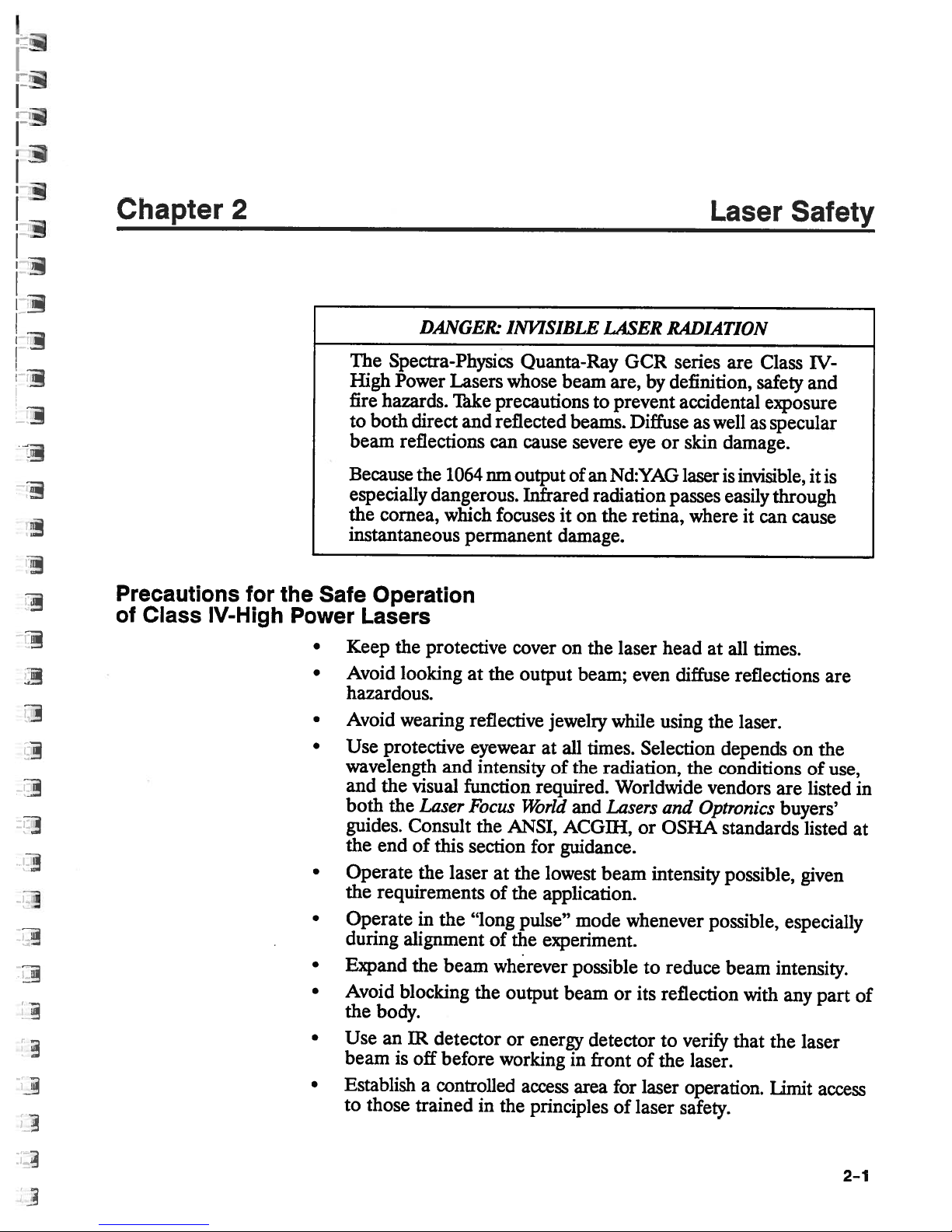
Because
especially
the
instantaneous
Safe
Operation
Lasers
Keep
Avoid
hazardous.
Avoid
Use
wavelength
and
both
guides.
the
end
Operate
the
requirements
Operate
during
Expand
Avoid
the
body.
Use
beam
Establish
to
those
DAJ’JGER.
Spectra-Physics
Power
hazards.
reflections
cornea,
the
looking
wearing
protective
the
the
blocking
an
is
Lasers
Take
direct
visual
and
the
1064
dangerous.
which
permanent
protective
and
function
Laser
Consult
of
this
the
laser
in
the
alignment
the
beam
IR
detector
off
before
a
controlled
trained
at
reflective
eyewear
intensity
Focus
the
section
“long
the
in
INVISIBLE
Quanta-Ray
whose
precautionstoprevent
reflected
cause
can
nm
output
Infrared
focuses
cover
the
output
jewelry
at
of
required.
World
ANSI,
for
the
at
of
of
wherever
working
the
pulse”
the
output
or
energy
access
the
principles
lowest
application.
experiment.
LASER
beam
it
damage.
on
all
ACGIII,
guidance.
beam
are,
beams.
severe
of
an Nd:YAG
radiation
on
the
the
laser
beam;
while
times.
the
radiation,
Worldwide
and
Lasers
beam
mode
possible
or
detector
in
front
area
for
of
GCR
Diffuse
eye
retina,
even
whenever
its
of
laser
RADIATION
series
by
definition,
accidental
as
or
skin
laser
passes
where
head
diffuse
using
Selection
the
and
Optronics
or OSHA
intensity
reduce
to
reflection
verify
to
the
laser.
laser
operation.
safety.
are
Class
safety
well
as
damage.
is
invisible,
easily
it
can
at
all
times.
reflections
the
laser.
depends
conditions
vendors
standards
possible,
possible,
beam
with
that
IV-
and
exposure
specular
it
through
cause
on
the
of
listed
are
buyers’
listed
given
especially
intensity.
any
part
the
laser
Limit
access
is
are
use,
in
at
of
2—1
 Loading...