

Spectra-Physics Millennia eV Series, Millennia eV 15, Millennia eV 10, Millennia eV 5 User Manual

Millennia eV
User’s Manual
Diode-Pumped, CW Visible Laser Systems
Millennia eV 15
Millennia eV 10
Millennia eV 5
This laser product complies with performance
standards of United States Code of Federal
Regulations, Title 21, Chapter 1 – Food and
Drug Administration, Department of Heal th and
Human Services, Subchapter J – Parts
1040.10 or 1040.11, as applicable.
Spectra-Physics
3635 Peterson Way
Santa Clara, CA 95054
Part Number 90062440
June 2013
Revision A

Copyright © 2013 Newport Corporation. All rights reserved.
Newport, the Newport logo, and other Newport company and product names referenced in the document are
registered trademarks, trademarks, or service m arks of Newport Corpor ation or its subsidiaries. Other comp any
and product names may be the trademarks of the respective co mpanies with which they are associated.
Spectra-Physics ma kes no express or implied re presentations or warranties with respect to the contents or use
of this manual, and specifically disclaims any implied warranties of merchantability or fitness for a particular
purpose. In no event is Spectra-Physics liab le for any direct, indirect, special, incidental, or consequential
damages resulting from any defects in this documentation.
This manual is copyrighted with all rights reserved. Under the copyrigh t laws, this manu al can not be cop ied in
whole or in part without the express written consent of Spectra-Physics. Documents that are authorized to be
copied must bear all the proprietary and copyright notices of the original.
Every effort has been made to ensure that the information in this manual is accurate. Spectra-Physics further
reserves the right to revise this manual and to make changes to its contents at any time, without obligation to
notify any person or entity of such revisions or changes.
If you encounter any difficulty with the co ntent or style of this manual or encounter problems with the laser itself,
please let us know.
“Form for Problems and Solutions” aids in bringing such issues to our attention.

Preface
About this Guide
The Spectra-Physics Millennia eV system is a diode-pumped, continuous-wave, visible
laser system. This manual contains information for the safe installation, operation, and
maintenance of the laser system.
Overview of this Guide
The Millennia eV User’s Manual includes the following sections:
Chapter 1, “Introduction,” is a brief overview of the Millennia eV system.
Chapter 2, “Laser Safety,” contains warnings and important information regarding
laser safety. Review this chapter before using the Millennia eV system.
Chapter 3, “Laser Description,” provides a description of the Millennia eV laser
system and concludes with system specifications and outline drawings. For optical
specifications, visit the Newport website at
http://www.newport.com/Millennia-eV-High-Power-CW-DPSS-Lasers/1011478/1
033/info.aspx
Chapter 4, “Controls, Indicators, and Connections,” describes the external control
features of the Millennia eV system.
Chapter 5, “Installation,” contains instructions for installing the system, including
hook-up diagrams and lists of required components.
Chapter 6, “Preparing for Operation,”provides instructions for installing the USB
driver and GUI software.
Chapter 7, “Operation,” describes in detail how to operate the laser.
Chapter 8, “Maintenance,” is intended as a guide for routine maintenance and
diagnosing and fixing common problems.
Chapter 9, “Customer Service,” describes our product warranty, return policy, and
training programs, and provides information on contacting customer service,
including a list of our service center locations.
Appendix A, “Programming Reference Guide,” contains the command reference.
“Notes” provides space to keep track of the service history for the Millennia eV
laser.
“Form for Problems and Solutions” is our feedback form, which the user can use to
report problems with our instruments or documentation, submit comments, suggest
new features, or request more information.
iii

Overview of this Guide
iv Preface
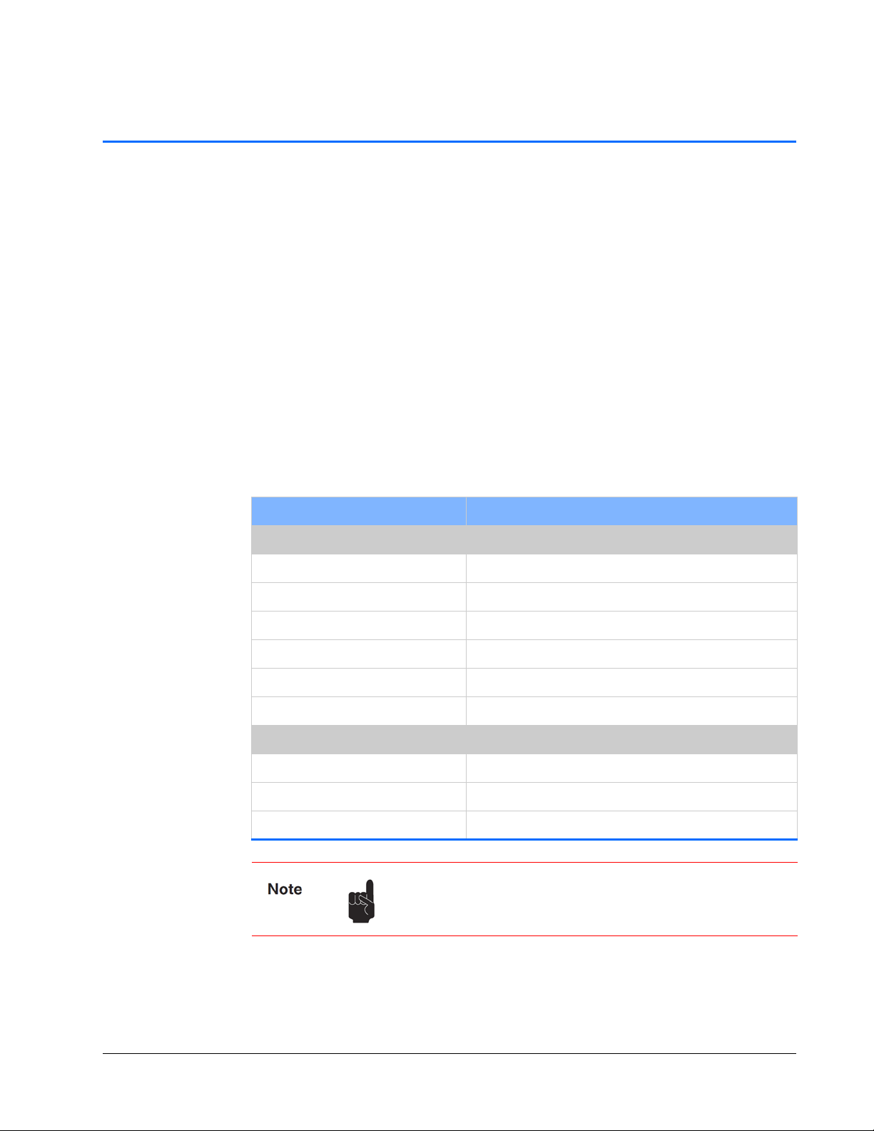
Environment al Specifications
CE Electrical Equipment Requirements
For information regarding the equipment needed to provide the required electrical
service, refer to specification EN-60309, “Plug, Outlet and Socket Couplers for
Industrial Uses,” listed in the official Journal of the European Communities.
Environmental Specifications
The environmental conditions under which the laser system function are listed at
http://www.newport.com/Millennia-eV-High-Power-CW-DPSS-Lasers/1011478/1
033/info.aspx
These specifications reflect indoor use conditions.
Feature Specification
Operating
Temperature ra ng e 18 °C to 35°C
Altitude 0 to 3,000 m
Relative humidity < 80%, non-condensing
Mains supply voltage Do not exceed ± 10% of the nominal voltage
Insulation category II
Pollution degree 2
Non-operating
Temperature ra ng e -20°C to 50°C
Altitude 0 to 12,000 m
Relative humidity < 90%, non-condensing
Also see “Specifications” for power, heat, and cooling
specifications.
v

FCC Regulations
FCC Regulations
This equipment has been tested and found to comply with the limits for a Class A digital
device pursuant to Part
reasonable protection against harmful interference when the equipment is operated in a
commercial environment. This equipment generates, uses and can radiate radio
frequency energy and, if not installed and used in accordance with the instruction
manual, can cause harmful interference to radio communications. Operation of this
equipment in a residential area is likely to cause harmful interference, in which case the
user is required to correct the interference at his own expense.
Modifications to the laser system not expressly approved by Spectra-Physics could void
the user’s right to operate the equipment.
15 of the FCC Rules. These limits are designed to provide
CDRH Compliance
This product conforms to the requirements of 21 CFR 1040.10 CDRH.
vi Environmental Specifications
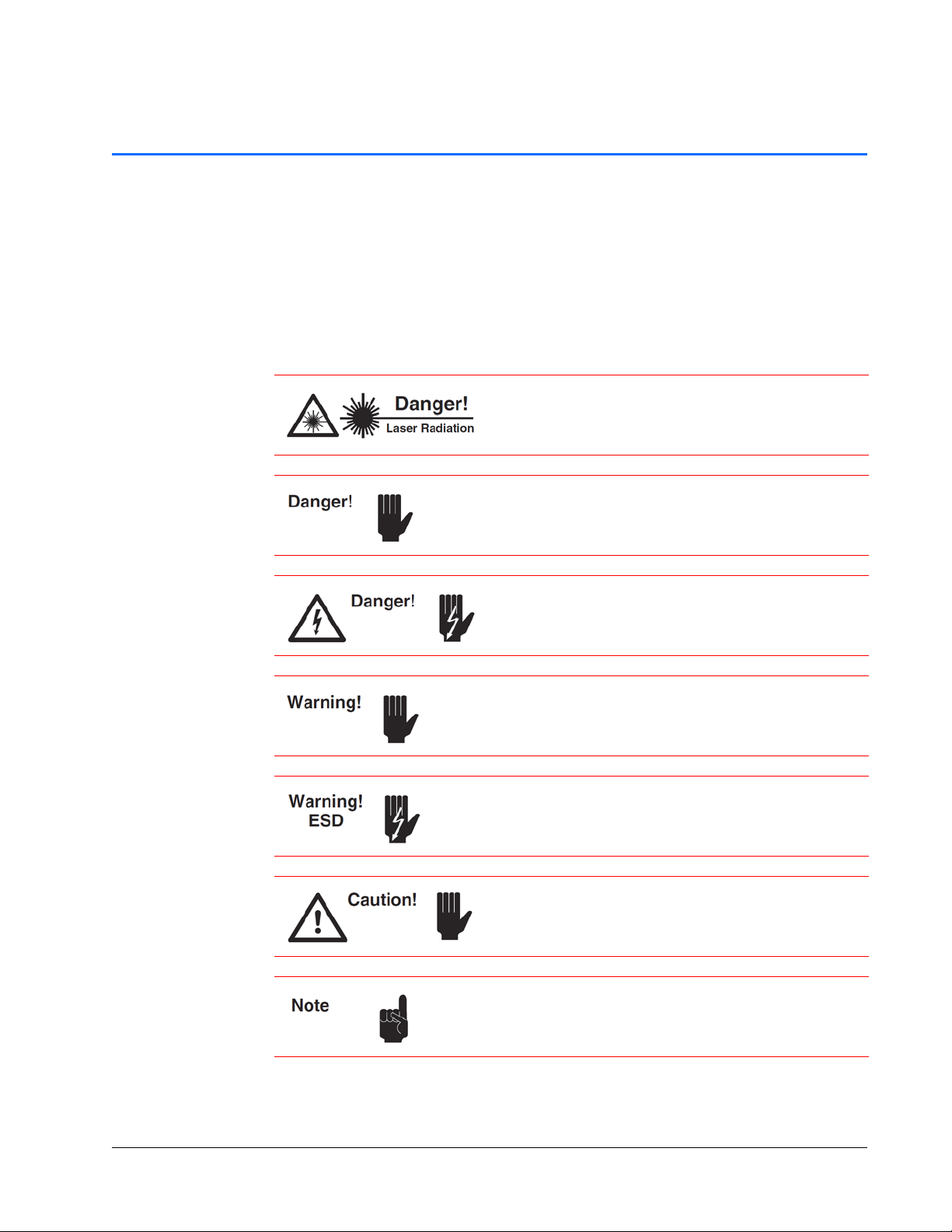
Warning Conventions
W arning Symbols
The following symbols are used throughout this manual to draw the user’s attention to
situations or procedures that require extra attention. They warn of health hazards,
damage to equipment, sensitive procedures, and exceptional circumstances. All
messages are set apart by a thin line above and below the text as shown here.
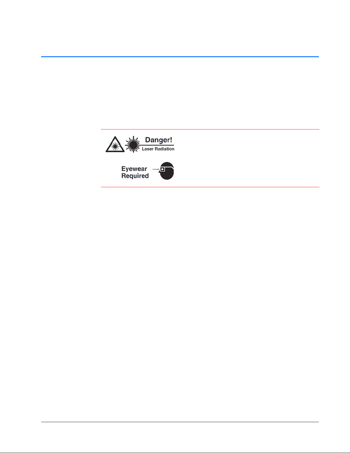
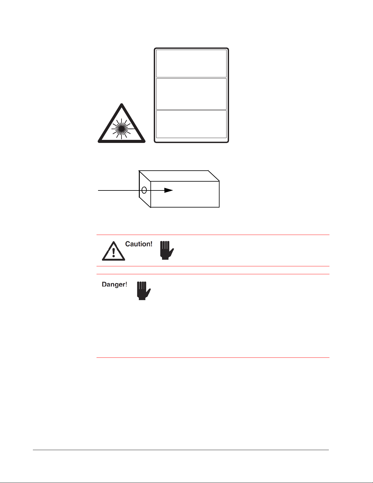
Condition or action may present a hazard to personal safety.
Laser radiation is present.
Condition or action may present an electrical hazard to
personal safety.
Condition or action may cause damage to equipment.
Action may cause electrostatic discharge and cause damage
to equipment.
Condition or action may cause poor performance or
error.
Text describes exceptional circumstances or makes a special
reference.
vii
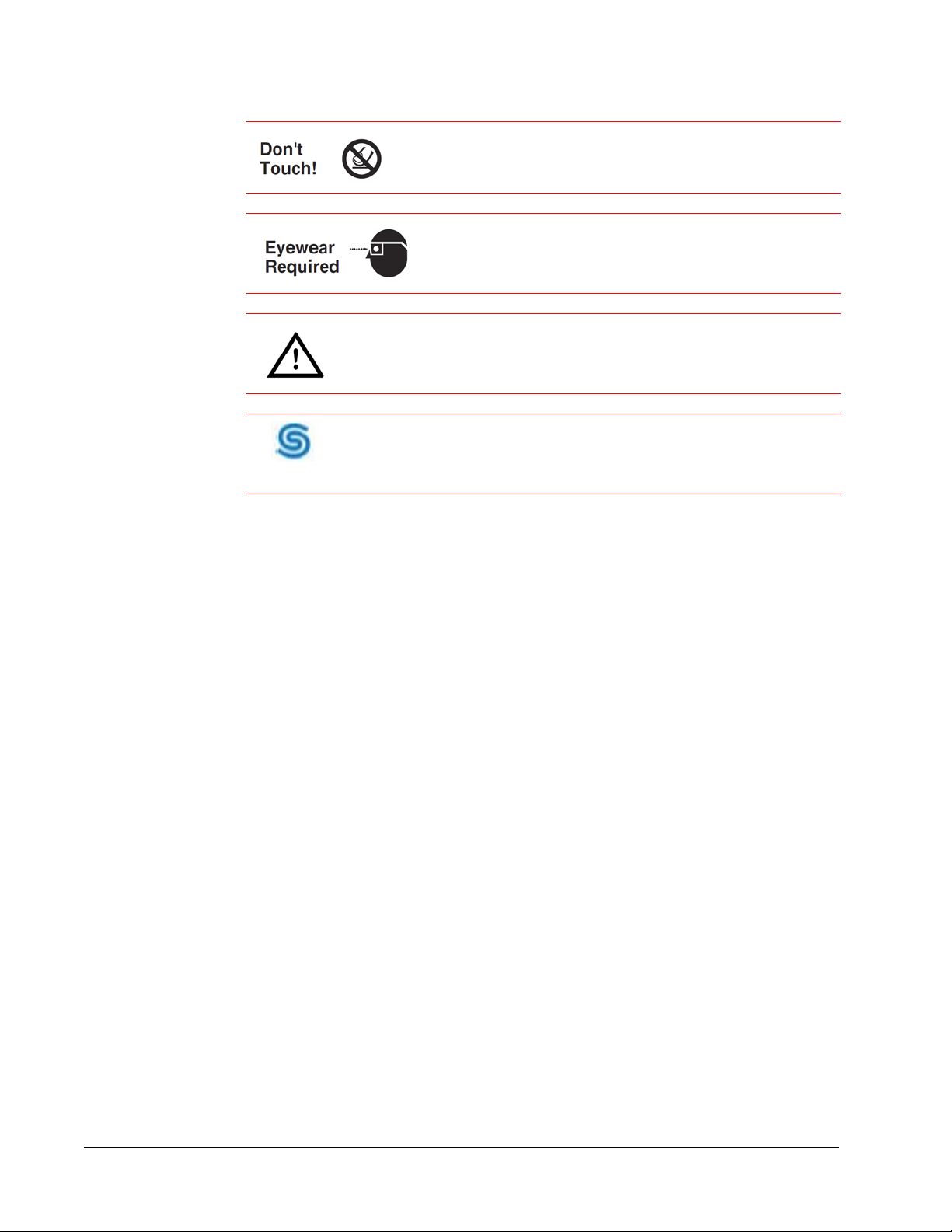
Warning Symbols
Factory Trained
Do not touch.
Appropriate laser safety eyewear should be worn during this
operation.
Refer to the manual before operating or using this device.
Serviceable only by Spectra-Physics factory trained personnel.
viii Warning Conventions

Table of Contents
Preface . . . . . . . . . . . . . . . . . . . . . . . . . . . . . . . . . . . . . . . . . . . . . . . . . . . . . . . . . . . . . . . .iii
Environmental Specifications . . . . . . . . . . . . . . . . . . . . . . . . . . . . . . . . . . . . . . . . . . . . . v
Warning Con v entions . . . . . . . . . . . . . . . . . . . . . . . . . . . . . . . . . . . . . . . . . . . . . . . . . . . vii
List of Figures . . . . . . . . . . . . . . . . . . . . . . . . . . . . . . . . . . . . . . . . . . . . . . . . . . . . . . . . .xiii
List of Tables . . . . . . . . . . . . . . . . . . . . . . . . . . . . . . . . . . . . . . . . . . . . . . . . . . . . . . . . . . xv
Standard Abbreviations . . . . . . . . . . . . . . . . . . . . . . . . . . . . . . . . . . . . . . . . . . . . . . . . xvii
Chapter 1: Introduction . . . . . . . . . . . . . . . . . . . . . . . . . . . . . . . 1-1
System Control . . . . . . . . . . . . . . . . . . . . . . . . . . . . . . . . . . . . . . . . . . . . . . . . . . . . .1-1
Environmental Control . . . . . . . . . . . . . . . . . . . . . . . . . . . . . . . . . . . . . . . . . . . . . . . . 1-2
Patents. . . . . . . . . . . . . . . . . . . . . . . . . . . . . . . . . . . . . . . . . . . . . . . . . . . . . . . . . . . . 1-2
Chapter 2: Laser Safety . . . . . . . . . . . . . . . . . . . . . . . . . . . . . . . 2-1
Safety Precautions for Class IV High-Power Lasers . . . . . . . . . . . . . . . . . . . . . . . . .2-1
Safety Device Locations . . . . . . . . . . . . . . . . . . . . . . . . . . . . . . . . . . . . . . . . . . . . . . 2-3
Emission and Status Indicators . . . . . . . . . . . . . . . . . . . . . . . . . . . . . . . . . . . . . .2-3
ENABLE Keyswitch . . . . . . . . . . . . . . . . . . . . . . . . . . . . . . . . . . . . . . . . . . . . . . .2-4
External Safety Interlock. . . . . . . . . . . . . . . . . . . . . . . . . . . . . . . . . . . . . . . . . . . .2-4
Power Disconnect. . . . . . . . . . . . . . . . . . . . . . . . . . . . . . . . . . . . . . . . . . . . . . . . .2-4
Maximum Emission Levels . . . . . . . . . . . . . . . . . . . . . . . . . . . . . . . . . . . . . . . . . . . . 2-5
Operating the Laser via a User-Created GUI. . . . . . . . . . . . . . . . . . . . . . . . . . . . . . .2-5
CE Radiation Control Drawings and Labels. . . . . . . . . . . . . . . . . . . . . . . . . . . . . . . .2-6
Label Placement. . . . . . . . . . . . . . . . . . . . . . . . . . . . . . . . . . . . . . . . . . . . . . . . . .2-6
Label Illustrations . . . . . . . . . . . . . . . . . . . . . . . . . . . . . . . . . . . . . . . . . . . . . . . . .2-8
CE Declaration of Conformity . . . . . . . . . . . . . . . . . . . . . . . . . . . . . . . . . . . . . . . . . . 2-9
WEEE Recycling Label . . . . . . . . . . . . . . . . . . . . . . . . . . . . . . . . . . . . . . . . . . . . . . 2-10
Other Hazards . . . . . . . . . . . . . . . . . . . . . . . . . . . . . . . . . . . . . . . . . . . . . . . . . .2-10
Additional Safety Resources . . . . . . . . . . . . . . . . . . . . . . . . . . . . . . . . . . . . . . . . . .2-10
Laser Safety Standards . . . . . . . . . . . . . . . . . . . . . . . . . . . . . . . . . . . . . . . . . . . 2-10
Equipment and Training . . . . . . . . . . . . . . . . . . . . . . . . . . . . . . . . . . . . . . . . . . .2-11
Chapter 3: Laser Description . . . . . . . . . . . . . . . . . . . . . . . . . . . . 3-1
Overview . . . . . . . . . . . . . . . . . . . . . . . . . . . . . . . . . . . . . . . . . . . . . . . . . . . . . . . . . .3-1
ix

Millennia eV Series System . . . . . . . . . . . . . . . . . . . . . . . . . . . . . . . . . . . . . . . . . . . .3-1
Millennia eV Laser Head . . . . . . . . . . . . . . . . . . . . . . . . . . . . . . . . . . . . . . . . . . . . . .3-2
Frequency Doubling . . . . . . . . . . . . . . . . . . . . . . . . . . . . . . . . . . . . . . . . . . . . . . .3-2
Light Pick-off and Power Control . . . . . . . . . . . . . . . . . . . . . . . . . . . . . . . . . . . . .3-3
System Control . . . . . . . . . . . . . . . . . . . . . . . . . . . . . . . . . . . . . . . . . . . . . . . . . . .3-3
Specifications . . . . . . . . . . . . . . . . . . . . . . . . . . . . . . . . . . . . . . . . . . . . . . . . . . . . . . .3-3
Chiller Specifications. . . . . . . . . . . . . . . . . . . . . . . . . . . . . . . . . . . . . . . . . . . . . . .3-5
Outline Drawings . . . . . . . . . . . . . . . . . . . . . . . . . . . . . . . . . . . . . . . . . . . . . . . . . . . .3-6
Block Diagrams . . . . . . . . . . . . . . . . . . . . . . . . . . . . . . . . . . . . . . . . . . . . . . . . . . . . .3-7
Chapter 4: Controls, Indicato rs, and Connections . . . . . . . . . . . . . . . . 4-1
Laser System Controls. . . . . . . . . . . . . . . . . . . . . . . . . . . . . . . . . . . . . . . . . . . . . . . .4-1
ANALOG Interface . . . . . . . . . . . . . . . . . . . . . . . . . . . . . . . . . . . . . . . . . . . . . . . . . . .4-4
Monitoring Laser Status Via the ANALOG Port . . . . . . . . . . . . . . . . . . . . . . . . . . . . .4-5
Using the Indicator Outputs . . . . . . . . . . . . . . . . . . . . . . . . . . . . . . . . . . . . . . . . .4-5
Chapter 5: Installation . . . . . . . . . . . . . . . . . . . . . . . . . . . . . . . . 5-1
Pre-Installation Check . . . . . . . . . . . . . . . . . . . . . . . . . . . . . . . . . . . . . . . . . . . . . . . .5-1
Required Tools . . . . . . . . . . . . . . . . . . . . . . . . . . . . . . . . . . . . . . . . . . . . . . . . . . .5-1
Utility Requirements . . . . . . . . . . . . . . . . . . . . . . . . . . . . . . . . . . . . . . . . . . . . . . .5-1
Mounting the Laser Head. . . . . . . . . . . . . . . . . . . . . . . . . . . . . . . . . . . . . . . . . . . . . .5-2
Connecting the System . . . . . . . . . . . . . . . . . . . . . . . . . . . . . . . . . . . . . . . . . . . . . . .5-2
AC Power Considerations. . . . . . . . . . . . . . . . . . . . . . . . . . . . . . . . . . . . . . . . . . .5-3
Analog Control Considerations . . . . . . . . . . . . . . . . . . . . . . . . . . . . . . . . . . . . . . .5-3
Installing the Chiller . . . . . . . . . . . . . . . . . . . . . . . . . . . . . . . . . . . . . . . . . . . . . . . . . .5-3
General Information . . . . . . . . . . . . . . . . . . . . . . . . . . . . . . . . . . . . . . . . . . . . . . .5-3
Installation. . . . . . . . . . . . . . . . . . . . . . . . . . . . . . . . . . . . . . . . . . . . . . . . . . . . . . .5-4
Chapter 6: Preparing for Operation. . . . . . . . . . . . . . . . . . . . . . . . . 6-1
Installing the USB Driver and User GUI Software . . . . . . . . . . . . . . . . . . . . . . . . . . .6-1
Installing the Millennia eV USB Driver . . . . . . . . . . . . . . . . . . . . . . . . . . . . . . . . .6-1
Installing Millennia eV GUI Control Software . . . . . . . . . . . . . . . . . . . . . . . . . . . .6-5
Chapter 7: Operation. . . . . . . . . . . . . . . . . . . . . . . . . . . . . . . . . 7-1
Millennia eV GUI Menus. . . . . . . . . . . . . . . . . . . . . . . . . . . . . . . . . . . . . . . . . . . . . . .7-2
The Main Menu. . . . . . . . . . . . . . . . . . . . . . . . . . . . . . . . . . . . . . . . . . . . . . . . . . .7-2
The View Button . . . . . . . . . . . . . . . . . . . . . . . . . . . . . . . . . . . . . . . . . . . . . . . . . .7-3
Start-up Sequence . . . . . . . . . . . . . . . . . . . . . . . . . . . . . . . . . . . . . . . . . . . . . . . . . . .7-6
Operating the Laser . . . . . . . . . . . . . . . . . . . . . . . . . . . . . . . . . . . . . . . . . . . . . . . . . .7-8
Turning the Laser On and Off . . . . . . . . . . . . . . . . . . . . . . . . . . . . . . . . . . . . . . . .7-8
Shutter Control . . . . . . . . . . . . . . . . . . . . . . . . . . . . . . . . . . . . . . . . . . . . . . . . . . .7-8
Using Serial Commands . . . . . . . . . . . . . . . . . . . . . . . . . . . . . . . . . . . . . . . . . . . .7-9
x Table of Contents

SHG Autotune . . . . . . . . . . . . . . . . . . . . . . . . . . . . . . . . . . . . . . . . . . . . . . . . . . . 7-9
Alignment Mode Operation. . . . . . . . . . . . . . . . . . . . . . . . . . . . . . . . . . . . . . . . . . 7-9
Chapter 8: Maintenance . . . . . . . . . . . . . . . . . . . . . . . . . . . . . . . 8-1
Flushing and Refilling the Chiller . . . . . . . . . . . . . . . . . . . . . . . . . . . . . . . . . . . . . . . . 8-1
Maintenance Tips. . . . . . . . . . . . . . . . . . . . . . . . . . . . . . . . . . . . . . . . . . . . . . . . .8-1
Replacing the Coolant . . . . . . . . . . . . . . . . . . . . . . . . . . . . . . . . . . . . . . . . . . . . . 8-1
Diagnostics and Troubleshooting. . . . . . . . . . . . . . . . . . . . . . . . . . . . . . . . . . . . . . . .8-2
System Event Codes . . . . . . . . . . . . . . . . . . . . . . . . . . . . . . . . . . . . . . . . . . . . . .8-2
Troubleshooting Guide. . . . . . . . . . . . . . . . . . . . . . . . . . . . . . . . . . . . . . . . . . . . . 8-3
Chapter 9: Customer Service . . . . . . . . . . . . . . . . . . . . . . . . . . . . 9-1
Warranty . . . . . . . . . . . . . . . . . . . . . . . . . . . . . . . . . . . . . . . . . . . . . . . . . . . . . . . . . .9-1
Contacting Customer Service . . . . . . . . . . . . . . . . . . . . . . . . . . . . . . . . . . . . . . . . . .9-1
Return Policy and Instructions . . . . . . . . . . . . . . . . . . . . . . . . . . . . . . . . . . . . . . . . . .9-2
Service Programs . . . . . . . . . . . . . . . . . . . . . . . . . . . . . . . . . . . . . . . . . . . . . . . . . . .9-2
Service Centers . . . . . . . . . . . . . . . . . . . . . . . . . . . . . . . . . . . . . . . . . . . . . . . . . . . . .9-3
Appendix A: Programming Reference G uide. . . . . . . . . . . . . . . . . . . . . A-1
Conventions. . . . . . . . . . . . . . . . . . . . . . . . . . . . . . . . . . . . . . . . . . . . . . . . . . . . . . . .A-1
Basic Commands. . . . . . . . . . . . . . . . . . . . . . . . . . . . . . . . . . . . . . . . . . . . . . . . . . . .A-2
Important Commands . . . . . . . . . . . . . . . . . . . . . . . . . . . . . . . . . . . . . . . . . . . . . . . .A-5
Less Common Commands . . . . . . . . . . . . . . . . . . . . . . . . . . . . . . . . . . . . . . . . . . . .A-8
Form for Problems and Solutions . . . . . . . . . . . . . . . . . . . . . . . . . . . . . . . . . . . . . Form-1
Notes. . . . . . . . . . . . . . . . . . . . . . . . . . . . . . . . . . . . . . . . . . . . . . . . . . . . . . . . . . . . .Notes-1
Index. . . . . . . . . . . . . . . . . . . . . . . . . . . . . . . . . . . . . . . . .Index-1
Table of Contents xi

xii Table of Contents xiii

List of Figures
Figure 1-1: Millennia eV laser. . . . . . . . . . . . . . . . . . . . . . . . . . . . . . . . . . . . . . . . . . . . . .1-1
Figure 2-1: Safety warning labels (EN 60825-1: 2007, ANSI Z136.1 Section 4.7). . . . . .2-2
Figure 2-2: Beam dump . . . . . . . . . . . . . . . . . . . . . . . . . . . . . . . . . . . . . . . . . . . . . . . . . . 2-2
Figure 2-3: Laser head emission indicator . . . . . . . . . . . . . . . . . . . . . . . . . . . . . . . . . . . .2-3
Figure 2-4: Laser safety devices, rear panel . . . . . . . . . . . . . . . . . . . . . . . . . . . . . . . . . .2-4
Figure 2-5: Millennia eV system conformance labels, front (left) and rear (right). . . . . . .2-6
Figure 2-6: Millennia eV system conformance labels, bottom . . . . . . . . . . . . . . . . . . . . . 2-7
Figure 2-7: Millennia eV system conformance labels, top view . . . . . . . . . . . . . . . . . . . .2-7
Figure 2-8: Safety warning labels. . . . . . . . . . . . . . . . . . . . . . . . . . . . . . . . . . . . . . . . . . . 2-8
Figure 3-1: Millennia eV laser system outline drawing . . . . . . . . . . . . . . . . . . . . . . . . . . . 3-6
Figure 3-2: Interlock safety block diagram . . . . . . . . . . . . . . . . . . . . . . . . . . . . . . . . . . . . 3-7
Figure 3-3: Millennia eV system block diagram . . . . . . . . . . . . . . . . . . . . . . . . . . . . . . . .3-7
Figure 4-1: Millennia eV laser head, rear panel . . . . . . . . . . . . . . . . . . . . . . . . . . . . . . . . 4-1
Figure 4-2: Millennia eV laser emission indicator and output beam . . . . . . . . . . . . . . . . . 4-3
Figure 4-3: ANALOG output drain schematic. . . . . . . . . . . . . . . . . . . . . . . . . . . . . . . . . .4-5
Figure 5-1: System interconnect drawing. . . . . . . . . . . . . . . . . . . . . . . . . . . . . . . . . . . . .5-2
Figure 6-1: Setup icon . . . . . . . . . . . . . . . . . . . . . . . . . . . . . . . . . . . . . . . . . . . . . . . . . . . 6-2
Figure 6-2: Preparing to Install window . . . . . . . . . . . . . . . . . . . . . . . . . . . . . . . . . . . . . . 6-2
Figure 6-3: InstallShield wizard. . . . . . . . . . . . . . . . . . . . . . . . . . . . . . . . . . . . . . . . . . . . .6-3
Figure 6-4: Setup Status window . . . . . . . . . . . . . . . . . . . . . . . . . . . . . . . . . . . . . . . . . . . 6-3
Figure 6-5: Device Driver Installation wizard . . . . . . . . . . . . . . . . . . . . . . . . . . . . . . . . . .6-4
Figure 6-6: Driver installation in progress. . . . . . . . . . . . . . . . . . . . . . . . . . . . . . . . . . . . .6-4
Figure 6-7: Completing the Device Driver Installation window . . . . . . . . . . . . . . . . . . . . .6-5
Figure 6-8: Software installed successfully message. . . . . . . . . . . . . . . . . . . . . . . . . . . . 6-5
Figure 6-9: Setup file . . . . . . . . . . . . . . . . . . . . . . . . . . . . . . . . . . . . . . . . . . . . . . . . . . . . 6-6
Figure 6-10: .NET license agreement. . . . . . . . . . . . . . . . . . . . . . . . . . . . . . . . . . . . . . . . . 6-6
Figure 6-11: .NET installation progress . . . . . . . . . . . . . . . . . . . . . . . . . . . . . . . . . . . . . . . 6-6
Figure 6-12: Welcome window . . . . . . . . . . . . . . . . . . . . . . . . . . . . . . . . . . . . . . . . . . . . . .6-7
Figure 6-13: Select installation folder . . . . . . . . . . . . . . . . . . . . . . . . . . . . . . . . . . . . . . . . .6-7
Figure 6-14: Confirm installation window . . . . . . . . . . . . . . . . . . . . . . . . . . . . . . . . . . . . . . 6-8
Figure 6-15: Installing window . . . . . . . . . . . . . . . . . . . . . . . . . . . . . . . . . . . . . . . . . . . . . . 6-8
Figure 6-16: Installation Complete window. . . . . . . . . . . . . . . . . . . . . . . . . . . . . . . . . . . . . 6-9
Figure 6-17: Spectra-Physics desktop icon . . . . . . . . . . . . . . . . . . . . . . . . . . . . . . . . . . . . 6-9
Figure 7-1: Main menu . . . . . . . . . . . . . . . . . . . . . . . . . . . . . . . . . . . . . . . . . . . . . . . . . . .7-2
Figure 7-2: View menu . . . . . . . . . . . . . . . . . . . . . . . . . . . . . . . . . . . . . . . . . . . . . . . . . . .7-3
Figure 7-3: Communication window . . . . . . . . . . . . . . . . . . . . . . . . . . . . . . . . . . . . . . . . .7-4
Figure 7-4: Oven window . . . . . . . . . . . . . . . . . . . . . . . . . . . . . . . . . . . . . . . . . . . . . . . . .7-5
Figure 7-5: About menu . . . . . . . . . . . . . . . . . . . . . . . . . . . . . . . . . . . . . . . . . . . . . . . . . . 7-6
Figure 7-6: GUI connection in progress . . . . . . . . . . . . . . . . . . . . . . . . . . . . . . . . . . . . . . 7-7
Figure 7-7: Laser turning on notice. . . . . . . . . . . . . . . . . . . . . . . . . . . . . . . . . . . . . . . . . . 7-8

xiv List of Figures xv

List of Tables
Table 1-1: Millennia eV system patents. . . . . . . . . . . . . . . . . . . . . . . . . . . . . . . . . . . . . .1-2
Table 2-1: Maximum emission levels from the laser head . . . . . . . . . . . . . . . . . . . . . . .2-5
Table 2-2: Conformance label descriptions. . . . . . . . . . . . . . . . . . . . . . . . . . . . . . . . . . .2-6
Table 3-1: Millennia eV laser system general specifications. . . . . . . . . . . . . . . . . . . . . .3-3
Table 3-2: Millennia eV laser output characteristics . . . . . . . . . . . . . . . . . . . . . . . . . . . .3-4
Table 4-1: Laser head rear panel controls. . . . . . . . . . . . . . . . . . . . . . . . . . . . . . . . . . . .4-2
Table 4-2: IBM-PC/AT serial port pinout . . . . . . . . . . . . . . . . . . . . . . . . . . . . . . . . . . . . .4-4
Table 4-3: ANALOG port pin description. . . . . . . . . . . . . . . . . . . . . . . . . . . . . . . . . . . . .4-4
Table 7-1: Main menu features . . . . . . . . . . . . . . . . . . . . . . . . . . . . . . . . . . . . . . . . . . . .7-3
Table 7-2: Communication window features . . . . . . . . . . . . . . . . . . . . . . . . . . . . . . . . . .7-4
Table 7-3: SHG Oven window features. . . . . . . . . . . . . . . . . . . . . . . . . . . . . . . . . . . . . .7-5
Table 8-1: System event codes. . . . . . . . . . . . . . . . . . . . . . . . . . . . . . . . . . . . . . . . . . . .8-2
Table 8-2: Non-event faults . . . . . . . . . . . . . . . . . . . . . . . . . . . . . . . . . . . . . . . . . . . . . . .8-3
Table 8-3: Troubleshooting guide . . . . . . . . . . . . . . . . . . . . . . . . . . . . . . . . . . . . . . . . . . 8-3
Table 9-1: Service centers. . . . . . . . . . . . . . . . . . . . . . . . . . . . . . . . . . . . . . . . . . . . . . . .9-3

xvi List of Tables xvii

Standard Abbreviations
The following units, abbreviations, and prefixes are used in this Spectra-Physics
manual.
Unit Abbreviations
Quantity Unit Abbreviation
mass kilogram kg
length meter m
time second s
frequency hertz Hz
force newton N
energy joule J
power watt W
electric current ampere A
electric charge coulomb C
electric potential volt V
resistance ohm Ω
inductance henry H
magnetic flux weber Wb
magnetic flux density tesla T
luminous intensity candela cd
temperature Celsius C
pressure pascal Pa
capacitance farad F
angle radian rad

Prefixes
Prefixes
Prefix Power Abbreviation Prefix Power Abbreviation
tera (1012) T milli (10-3) m
giga (109) G micro (10-6) µ
mega (106) M nano (10-9) n
kilo (103) k pico (10
deci (10-1) d femto (10
centi (10-2) c atto (10
-12
) p
-15
) f
-18
) a
Abbreviations and Acronyms
Abbreviation Description
AC alternating current
ACGIH American Conference of Governmental and Industrial
Hygienists
ALPS active laser purification system
ANSI American National Standards Institute
AOM acousto-optic modulator
AR antireflection
CDRH Center for Devices and Radiological Health
CW continuous wave
DC direct current
fs femtosecond or 10
LBO lithium triborate
ns nanosecond or 10-9 second
ps picosecond or 10
-15
-12
second
second
RF radio frequency
SCPI Standard Commands for Programmable Instruments
SHG second harmonic generator
THG third harmon ic generator
UV ultraviolet
xviii Standard Abbreviations

Abbreviations and Acronyms
Abbreviation Description
VAC volts, alternating current
VDC volts, direct current
λ wavelength
WEEE waste electrical and electronic equipment
Standard Abbreviations xix

Abbreviations and Acronyms
xx Standard Abbreviations
CHAPTER 1: Introduction
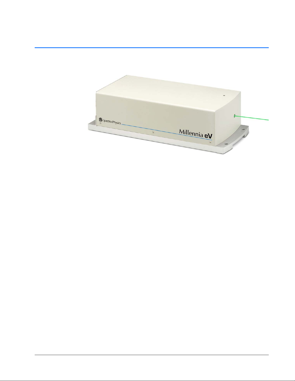
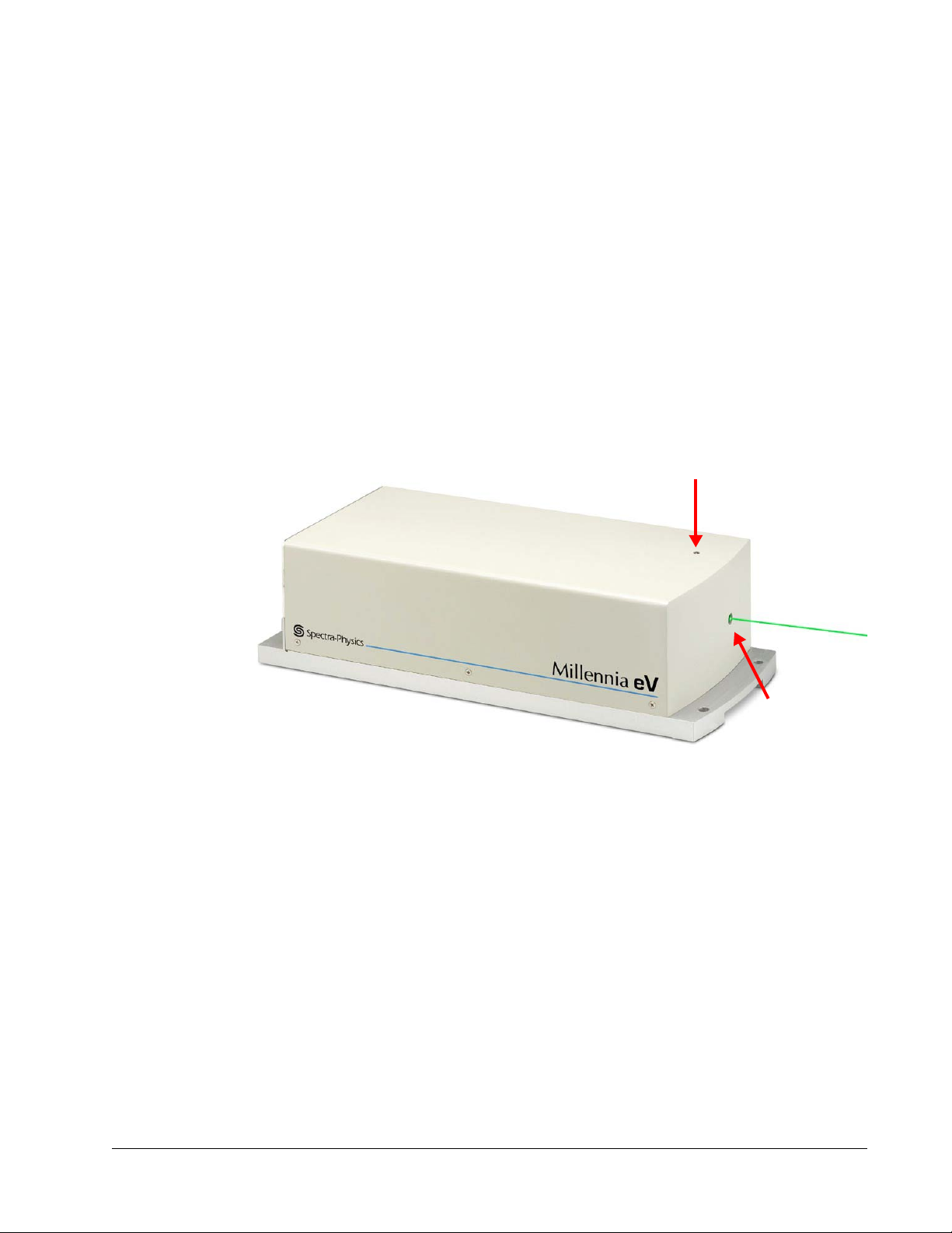
Figure 1-1 Millennia eV laser
The Spectra-Physics Millennia eV laser system is a diode-pumped, continuous-wave,
visible system. This laser system is a rugged, sealed unit designed for simple hands-free
operation.
The Millennia eV laser is smaller than competitive DPSS lasers of similar power. With
its intuitive GUI, automated command set, and superior design, the Millennia eV laser
is nearly maintenance free.
Millennia eV lasers have excellent near- and far-field beam pointing stability.
Some of the advantages of the Millennia eV laser are:
Reliable design and manufacture for high uptime
Lower cost of ownership
Excellent product value and low cost per watt
Robust manufacturing processes
The Millennia eV laser system was specifically designed for applications requiring a
high-quality beam, along with good mode quality in a cost-effective package. For a
more detailed description of the Millennia eV laser system, see
Description.”
System Control
During setup, a user-supplied computing device (typically a Windows-based personal
computer) must be connected to the Millennia eV laser head by means of either its
RS-232 or USB port to provide system control. Control software is provided on the
included USB memory stick for this purpose.
Chapter 3, “Laser
1-1

Environmental Control
Environmental Control
The Millennia eV laser system requires cooling fluid to remove heat and to stabilize the
temperature of various system components. A closed-loop chiller is used for this
purpose. The recirculating, temperature-controlled fluid flows to the laser head to
remove excess heat.
Patents
Millennia eV laser systems are manufactured under one or more of the following
patents.
Table 1-1 Millennia eV system patents
Millennia eV Laser Head
5,410,559 5,412,683 5,446,749 5,504,762
5,561,547 5,577,060 5,608,742 5,638,397
5,651,020 5,696,780 5,812,583 5,907,570
5,999,544 6,185,235 6,241,720 6,287,298
6,504,858 6,697,390 6,816,536 6,853,655
6,890,474 6,931,037 7,352,570 7,361,145
7,510,529 7,627,386 7,382,309 7,699,781
8,002,705 8,226,561
1-2 Introduction
CHAPTER 2: Laser Safety
This chapter provides important information on laser safety and Spectra-Physics
recommends that the user read it carefully.
The Millennia eV laser system is a Class IV laser that emits laser radiation that can
permanently damage eyes and skin. This section contains information about these
hazards and offers suggestions on how to safeguard against them.
The Spectra-Physics Millennia eV laser is a
Class
IV — High-Power Laser whose beam is, by
definition, a safety and fire hazard. T ake precautions to
prevent accidental exposure to both direct and
reflected beams. Diffuse as well as specular beam
reflections can cause severe eye or skin damage.
Residual light at 1064
might also be present.
Safety Precautions for Class IV High-Power Lasers
nm and 8xx nm wave-lengths
Wear protective eyewear at all times. Eyewear selection depends on the wavelength
and intensity of the radiation, the conditions of use, and the visual function required.
Protective eyewear is available from suppliers listed in the Laser Focus World,
Lasers and Optronics, and Photonics Spectra buyer’s guides. Consult the ANSI and
ACGIH standards listed in
Maintain a high ambient light level in the laser operation area so that the eye’s pupil
“Additional Safety Resources” for guidance.
remains constricted, reducing the possibility of retinal damage.
Avoid looking at the output beam; even diffuse reflections are hazardous.
Avoid blocking the output beam or its reflections with any part of the body.
Establish a controlled access area for laser operation. Limit access to personnel
trained in the principles of laser safety.
Enclose beam paths wherever possible.
Post prominent warning signs near the laser operating area (Figure 2-1).
Install the laser so that the beam is either above or below eye level.
Set up shields to prevent any unnecessary specular reflections or beams from
escaping the laser operation area.
When the target is not present, set up a beam dump to capture the laser beam and
prevent accidental exposure (
Do not block off access to any disconnect device such as the keyswitch, shutter
Figure 2-2).
control, power cord, etc.
2-1
Safety Precautions for Class IV High-Power Lasers
VISIBLE AND / OR INVISIBLE
LASER RADIATION
Avoid eye or skin exposure
to direct or scattered radiation.
Nd:YVO
, Nd:YAG, or Nd:YLF Laser. Various
4
ultraviolet, visible or infrared wavelengths
may be emitted. Consult instruction manual.
Class 4 laser product per IEC 60825-1 (2007)
SICHTBARE UND / ODER UNSICHTBARE
LASERSTRAHLUNG
Bestrahlung von Haut oder Auge durch
direkte oder Streustahlung vermeiden.
Nd:YVO
, Nd:YAG, oder Nd:YLF Laser.
4
Verschiedene ultraviolett, sichtbara oder infrarote
Laserstrahlung kann austreten. Weitere
Informationen siehe Bedienungsanleitung.
Laserschutzklasse 4 nach IEC 60825-1 (2007)
RAYONNEMENT LASER
VISIBLE ET / OU INVISIBLE
Eviter l’exposition de l’œil ou de la peau
au rayonnement direct ou diffus.
Laser Nd:YVO
, Nd:YAG ou Nd:YLF.
Emission potentielle dans l’ultraviolet, visible ou infrarouge.
Laser de classe 4 conformément à IEC 60825-1 (2007)
4
Consulter le manuel d’utilisation.
0129-4842
Figure 2-1 Safety warning labels (EN 60825-1: 2007, ANSI Z136.1 Section 4.7)
Figure 2-2 Beam dump
Operating this laser without due regard for these precautions or
in a manner that does not comply with recommended
procedures may be dangerous. At all times during installation,
maintenance or service of the laser, avoid unnecessary
exposure to laser or collateral radiation
electronic product radiation, except laser radiation, emitted by a
laser product as a result of or necessary for the operation of a
laser incorporated into that product) that exceeds the accessible
emission limits listed in “Performance Standards for Laser
Products,” United States Code of Federal Regulations,
21CFR1040.10(d).
Use of controls or adjustments, or performance of
procedures other than those specified herein can
result in hazardous radiation exposure.
(defined as any
2-2 Laser Safety
Safety Device Locations
Emission indicator
(white)
Output
beam port
Safety Device Locations
Emission and Status Indicators
The system provides the following emission and power indicators:
A white EMISSION indicator on top of the laser head (Figure 2-3) turns on about 3
seconds before actual emission occurs.
The STATUS fault indicator (Figure 2-4) flashes amber during the harmonic crystal
warm-up sequence. When the unit is warmed up and all of the safety requirements
are met, the indicator turns green and blinks. This indicator turns red and blinks
when a fault has occurred.
Pin 14 of the ANALOG connector can be used to control an external emission
indicator.
Figure 2-3 Laser head emission indicator
Laser Safety 2-3
Safety Device Locations
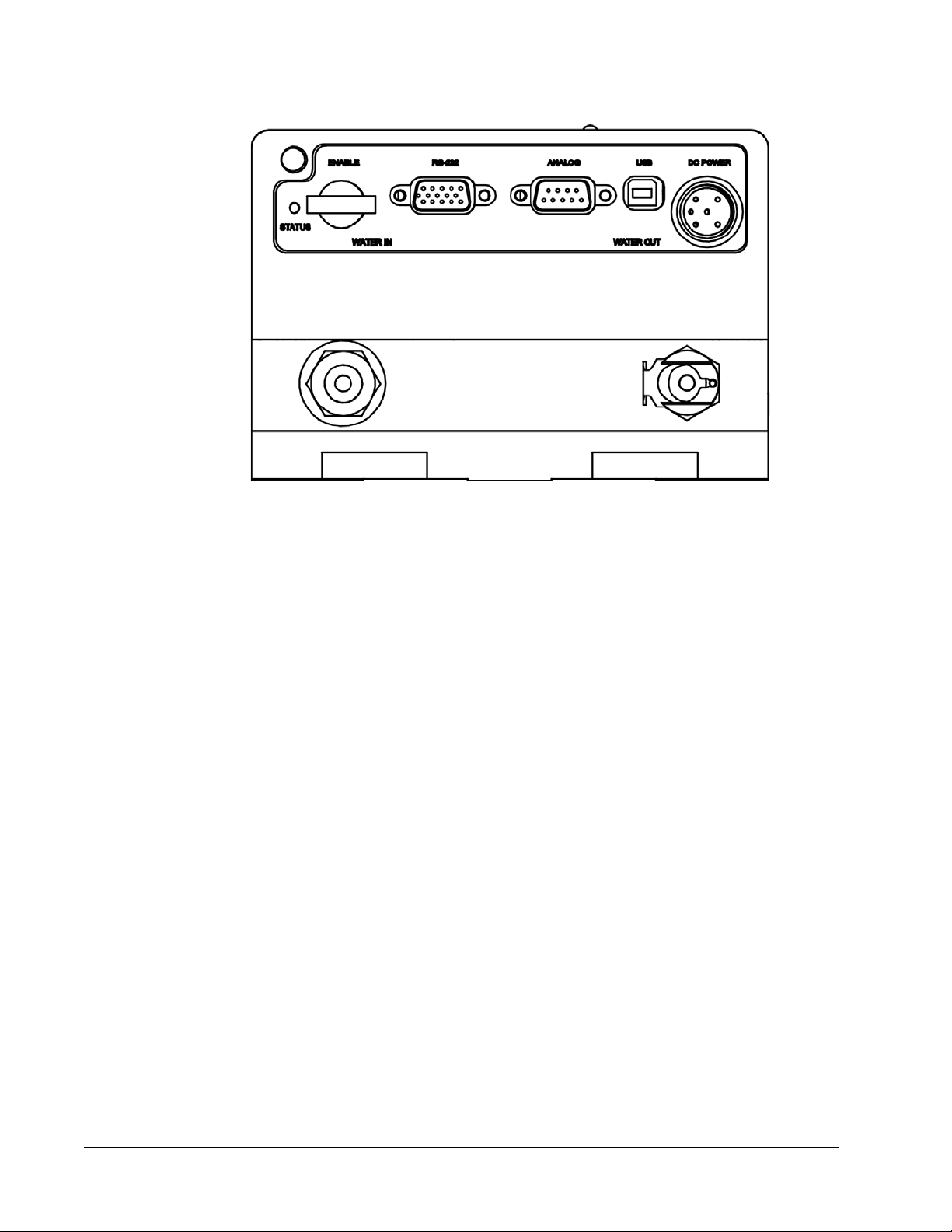
Figure 2-4 Laser safety devices, rear panel
ENABLE Keyswitch
The keyswitch on the rear panel (Figure 2-4) prevents unauthorized use of the laser
when it is turned to the horizontal (off) position and the key is removed. Placing this
switch in the
External Safety Interlock
Interlock pins 8 and 13 (Figure 2-4) of the ANALOG connector must be connected for
normal system operation. They can be used in an interlock circuit to terminate laser
emission when a normally closed safety switch wired to these pins is opened. Such a
switch can be attached to an access point, such as an entry panel, that might be opened
unexpectedly. See
requirements.
Power Disconnect
The utility unit is provided with a grounded appliance inlet. To help maintain the safety
of the equipment, it must be connected to a grounded connection. The ground should be
verified prior to use.
Access to the power connection cord should be maintained to allow the unit to be
disconnected from power in the event of an emergency.
ENABLE position allows the laser to be turned on when commanded.
Chapter 4, “Controls, Indicators, and Connections,” for the circuit
2-4 Laser Safety

Maximum Emission Levels
Maximum Emission Levels
Table 2-1 lists the maximum emission levels possible for the Millennia eV lasers. Use
this information for selecting appropriate laser safety eyewear and to implement
appropriate safety procedures. These values do not imply actual system power or
specifications.
The diode pump laser used in the Millennia eV laser system produces infrared light.
Laser light at longer wavelengths is generated in the production of green emission.
These wavelengths are confined to the inside of the laser head.
Table 2-1 Maximum emission levels from the laser head
Feature Specification
Emission wavelength Laser output: 532 nm
Maximum power 20 W
Operating the Laser via a User-Created GUI
The Millennia eV laser system can be controlled by a device provided by or software
written by the user. In this case, the following features must be provided for safety:
Keyswitch: Limits access to the laser and prevents it from being turned on. The
keyswitch can be a real key lock, a removable computer disk, a password that limits
access to computer control software, or a similar “key” implementation. The laser
must only operate when the key is present and in the ON position.
Emission indicator: Indicates laser energy is present or can be accessed. The
indicator can be a power-on lamp, a computer display that flashes a statement to this
effect, or an indicator on the control equipment specifically for this purpose. It need
not be marked as an emission indicator so long as its function is obvious. This
indicator is required on any control panel that affects laser output.
Laser Safety 2-5
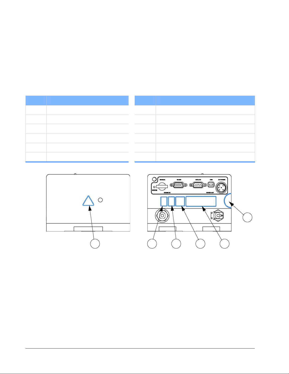
CE Radiation Control Drawings and Labels
126 7 2 1
9
CE Radiation Control Drawings and Labels
Label Placement
See “Label Illustrations” for images of the numbered labels on the device. The number
key for the following figures is listed in Tabl e 2-2.
Table 2-2 Conformance label descriptions
Number Description Number Description
1 Label, S/N head, CDRH 7 Label, WEEE
2 Label, CE conformity 8 Label, Euro danger Millennia eV
3 Label, class 4, warning 9 Label, void
4 Label, non-interlocked housing 10 Aperture label, visible and invisible laser radiation
5 Patent label, Millennia eV 11 Label, FCC class A compliance
6 Label, star burst 12 Label, .75 x .50 silver RoHS
Figure 2-5 Millennia eV system conformance labels, front (left) and rear (right)
2-6 Laser Safety
CE Radiation Control Drawings and Labels
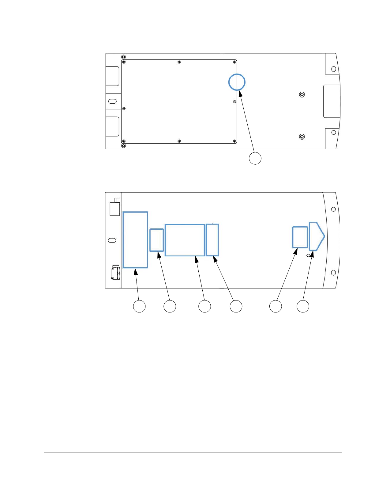
9
8 3 11 45 10
Figure 2-6 Millennia eV system conformance labels, bottom
Figure 2-7 Millennia eV system conformance labels, top view
Laser Safety 2-7
CE Radiation Control Drawings and Labels
1
23
4
8
6
7
5
9
10 11 12
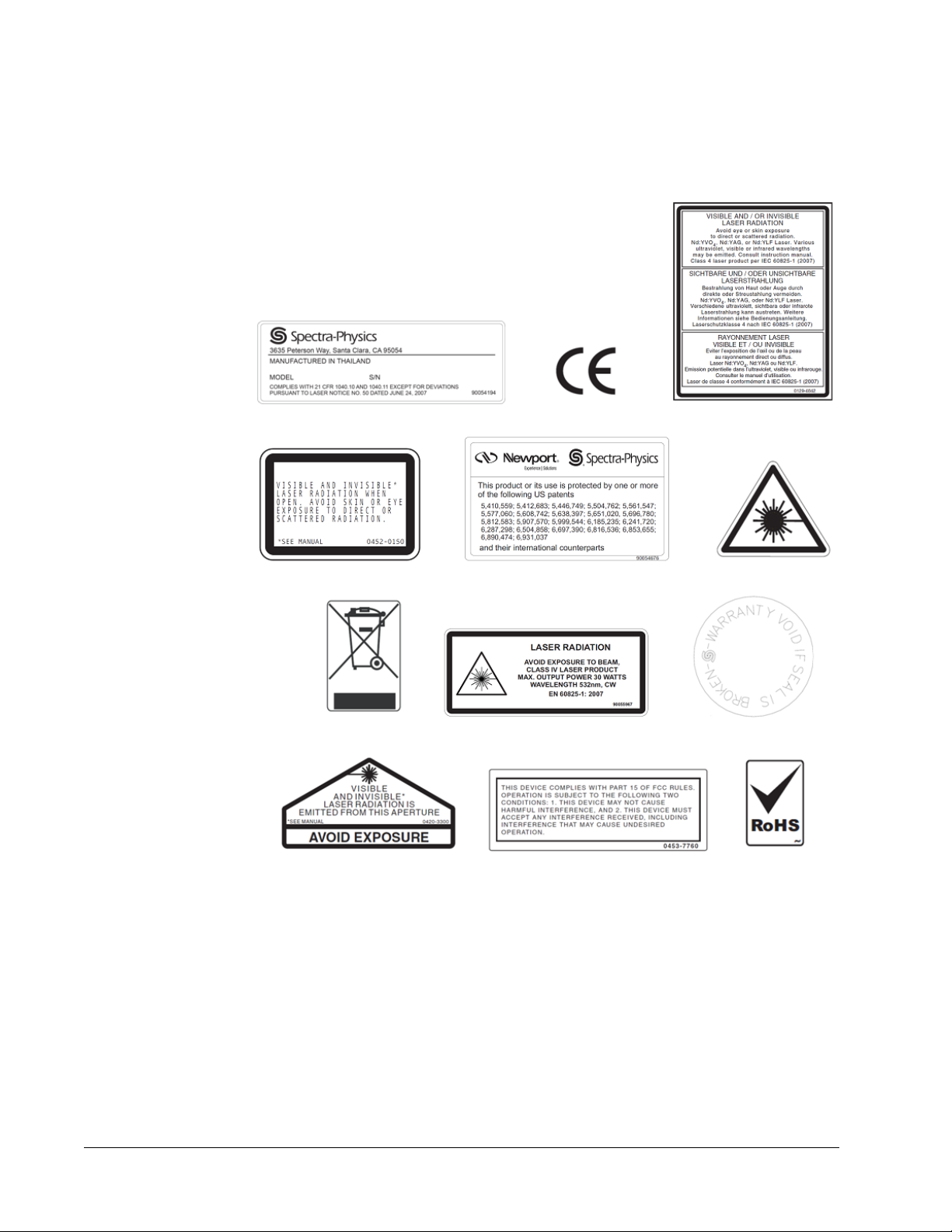
Label Illustrations
See “Label Placement” for the locations of the numbered labels on the device.
Figure 2-8 Safety warning labels
2-8 Laser Safety

CE Declaration of Conformity
CE Declaration of Conformity
We,
Spectra-Physics, a Newport Corporation Brand
3635 Peterson Way
Santa Clara, CA 95054
United States of America
declare under sole responsibility that the:
Millennia eV Family of Diode Pumped Solid State Lasers
Manufactured after September 10, 2012
Meet the intent of EMC Directive 2004/108/EC for Electromagnetic Compatibility and
2006/95/EC for the Low Voltage Directive. Compliance was demonstrated to the
following specifications as listed in the official Journal of the European Communities:
EMC Dir ective 2004/108/EC
EN 61000-6-4: 2007: Emission standard for industrial environments—generic
standards
EN 61000-3-2: 2006: Limits for harmonic current emissions (equipment input
up to and including 16A per phase)
EN 61000-3-3: 2008: Section 3: Limitation of volt ag e ch anges, vo ltage fluctua-
tions, and flicker
EN 61000-6-2: 2005: Generic sta ndards—Immunity for industrial environments
EN 61000-4-2: 2009: Part 4: Section 2: Electrostatic discharge immunity test
EN 61000-4-3: 2011: Part 4: Section 3: Testing and measurement tech-
niques—radiated, radio-frequency, electromagnetic field
EN 61000-4-4: 2010: Part 4-4: Testing and measurement techniques—electri-
cal fast transient/burst immunity test
EN 61000-4-5: 2006: Testing and measurement techniques—surge immunity
test
EN 61000-4-6: 2009: Part 4 - 6: Testing and measurement
techniques
quency fields
EN 61000-4-8: 2010: Testing and measurement techniques—power frequency
magnetic field immunity test
EN 61000-4-11: 2004: Testing and measurement techniques — voltage dips,
short interruptions, and voltage variations
—immunity to conducted disturbances induced by radio-fre-
Low Voltage Directive 2006/95/EC
EN 61010-1: 2010 Safety requirements for electrical equipment for measure-
ment, control, and laboratory use — Part 1 General requirements
EN 60825-1: 2007 Part 1—Safety of Laser Products—Equipment Classification,
Requirements, and User’s Guide
I, the undersigned, hereby declare that the equipment specified above conforms to the
above Directives and Standards.
David Allen
Vice President/General Manager
Spectra-Physics, a Newport Corporation Brand
September 10, 2012
Laser Safety 2-9

WEEE Recycling Label
WEEE Recycling Label
To Our Customers in the European Union:
As the volume of electronics goods placed into commerce continues to grow, the
European Union is taking measures to regulate the disposal of waste from electrical and
electronic equipment. Toward that end, the European Parliament has issued a directive
instructing European Union member states to adopt legislation concerning the
reduction, recovery, re-use, and recycling of waste electrical and electronic equipment
(WEEE). In accordance with this directive, the accompanying product has been marked
with the WEEE symbol (label 7 in
The main purpose of the symbol is to designate that, at the end of its useful life, the
accompanying product should not be disposed of as normal municipal waste, but instead
should be transported to a collection facility that ensures the proper recovery and
recycling of the product’s components. The symbol also signifies that this product was
placed on the market after 13 August 2005. At this time, regulations for the disposal of
waste electrical and electronic equipment vary within the member states of the
European Union. Please contact a Newport
information concerning the proper disposal of this product.
Figure 2-8).
/ Spectra-Physics representative for
Other Hazards
In addition to optical hazards, the Millennia eV equipment can present fire, electrical, or
mechanical hazards. Available electrical power within the box is <
Appropriate cooling must be provided during operation. Electrical voltages contained
within the unit can exceed 24
The unit weight is <
elements have been implemented in the product to reduce these hazards. Failure to
follow the instructions within this manual can impair the protection provided by these
elements.
7 kg (< 16 lb.) and must be supported properly. Safety design
volts. Always operate the unit with the covers in place.
Additional Safety Resources
Laser Safety Standards
Safe Use of Lasers (Z136.1)
American National Standards Institute (ANSI)
25 West 43rd Street, 4th Floor
New York, NY 10036
Tel: (212) 642-4900
600 watts.
Occupational Safety and Health Administration (Osha Standard, 01-05-001-pub8-1.7
U. S. Department of Labor
200 Constitution Avenue N. W., Room N3647
2-10 Laser Safety

Additional Safety Resources
Washington, DC 20210
Tel: (202) 693-1999
Website: http://www.osha.gov
A Guide for Control of Laser Hazards, 4th Edition, Publication #0165
American Conference of Governmental and Industrial Hygienists (ACGIH)
1330 Kemper Meadow Drive
Cincinnati, OH 45240
Tel: (513) 742-2020
Website: http://www.acgih.org/home.htm
Laser Institute of America
13501 Ingenuity Drive, Suite 128
Orlando, FL 32826
Tel: (800) 345-2737
Website: http://www.laserinstitute.org
International Electrotechnical Commission
Journal of the European Communities
IEC 60825-1 Safety of Laser Products—Part 1: Equipment classification, requirements,
and user’s guide
Tel: +41 22-919-0211 Fax: +41 22-919-0300
Website: http://www.iec.ch
Cenelec
35, Rue de Stassartstraat
B-1050 Brussels, Belgium
Tel: +32 2 519 68 71
Website: http://www.cenelec.eu
Document Center, Inc.
111 Industrial Road, Suite 9
Belmont, CA 94002
Tel: (650) 591-7600
Website: http://www.document-center.com
Equipment and Training
Laser Safety Guide
Laser Institute of America
13501 Ingenuity Drive, Suite 128
Orlando, FL 32826
Tel: (800) 34LASER
Website: http://www.laserinstitute.org
Laser Focus World Buyer's Guide
Laser Focus World
Pennwell Publishing
98 Spit Rock Road
Nashua, NH 03062
Tel: (603) 891-0123
Website: http//:pennwell.365media.com/laser focus world/search.html
Laser Safety 2-11

Additional Safety Resources
Photonics Spectra Buyer's Guide
Photonics Spectra
Laurin Publications
Berkshire Common
PO Box 4949
Pittsfield, MA 01202-4949
Tel: (413) 499-0514
Website: http://www.photonics.com
2-12 Laser Safety

CHAPTER 3: Laser Description
This chapter provides information about the Millennia eV laser system.
Overview
The Spectra-Physics Millennia eV laser system is a diode-pumped, continuous-wave,
visible laser that produces a superior quality, 532
The Millennia eV laser system was specifically designed for applications requiring a
continuous-wave, high-quality beam, along with good mode quality in a cost-effective
package. This laser is a rugged, sealed unit designed for simple, hands-free operation.
The laser head contains all system electronics and optical components, along with
microprocessors and memory for storing system parameters. The Millennia eV system
is designed for maximum reliability with minimum complexity. The laser head does not
require any adjustments for normal operation.
The host system connects to the laser through the SERIAL or USB port. Analog/TTL
control signals via the
serial commands. The
“Controls, Indicators, and Connections,” and the commands are listed in Appendix A,
“Programming Reference Guide.”
ANALOG port can either be used alone or in combination with
ANALOG and SERIAL controls are fully described in Chapter 4,
nm green output beam.
The following sections briefly describe the design of the Millennia eV laser head.
Controls and connections are described in
Connections,” and the methods of operating the laser are described in Chapter 7,
“Operation.”
Millennia eV Series System
The Millennia eV system comprises these basic components:
Millennia eV water-cooled laser head
48 VDC utility unit
Computer with Millennia eV control software
A recirculating chiller is required for cooling the laser head. The customer can order a
chiller from Spectra-Physics as optional equipment.
The Millennia eV laser system has three models:
Millennia eV 15 (15 W of CW 532 nm)
Millennia eV 10 (10 W of CW 532 nm)
Millennia eV 5 (5 W of CW 532 nm)
Chapter 4, “Controls, Indicators, and
3-1

Millennia eV Laser Head
The controller for the Millennia eV laser system is a customer-supplied computer or
laptop. The customer can order a laptop from Spectra-Physics as optional equipment.
The following sections describe the laser head and utility unit hardware. Operating the
Millennia eV laser system is described in
described in the user’s manual shipped with the chiller.
Chapter 7, “Operation.” The chiller is
Millennia eV Laser Head
The optical cavity of the Millennia eV laser head uses a folded cavity resonator. In this
design, the fiber-coupled output from the diode module is used to end-pump a vanadate
crystal. The crystal is the driving engine of the laser. It absorbs the diode laser light and
emits its own laser beam light at 1064
Millennia eV cavity.
A telescope is used to focus the pump light through a dichroic fold mirror and into the
vanadate laser crystal. This dichroic mirror is highly transmissive at the diode pump
laser wavelength and highly reflective at 1064
nm, which is resonated (and confined) in the
nm.
Frequency Doubling
Frequency-doubling converts the 1064 nm light from the laser crystal to the green
nm light that becomes the output of the laser.
532
A noncritically phase-matched lithium triborate (LBO) crystal placed in the cavity
converts the intracavity light to the green 532
acceptance angle, which makes it insensitive to any slight misalignment of the Millennia
eV cavity. A compact, low power, temperature-regulating oven is used to maintain the
crystal at the appropriate phase-matching temperature to keep the 532
optimized.
The patented Quiet Multi-Axial Mode Doubling (QMAD) technique provides
exceptionally low-noise performance. It uses a very large number of axial modes and
balances gain, nonlinear conversion, and excited-state lifetime to provide high power
and extremely stable amplitude.
Virtually all the doubled light reflects off the dichroic output coupler where the beam is
then directed out of the laser. A beam splitter and photodiode sample the output and
provide feedback to the pump laser driver to provide a constant output in power mode
operation. A shutter placed outside the cavity enclosure blocks the beam until
commanded to open.
A dichroic mirror allows the 532 nm light to exit the cavity while keeping the 1064 nm
light inside the cavity. The 90° polarization rotator aligns the polarization to the vertical
axis required in many applications.
nm wavelength. LBO offers a large
nm power
3-2 Laser Description

Specifications
Light Pick-off and Power Control
A beam splitter near the output of the laser head samples a small portion of the green
beam and directs it to the photodetector for the power control feedback circuit. Power
mode is the standard operating mode for the Millennia eV laser; the control loop adjusts
the diode pump current to keep the power constant to within ±
1% of the set point.
System Control
The Millennia eV laser operates through a Spectra-Physics supplied GUI for day-to-day
operation. This GUI is described in
In the context of this manual, the diode laser module is
sometimes referred to simply as the “diode,” e.g., “the diode
current.”
Chapter 7, “Operation.”
Specifications
Table 3-1 lists the general characteristics of the Millennia eV laser. Due to our
Complete environmental specifications for operating and non-operating conditions are
listed in
Table 3-1 Millennia eV laser system general specifications
Feature Specification
Operating Conditions
continuous product improvement program, specifications can change without
notice. For the most current specifications and performance characteristics, visit the
Newport website at
http://www.newport.com/Millennia-eV-High-Power-CW-DPSS-Lasers/1011478/1
033/info.aspx
“Environmental Specifications.”
Warm-up time (from cold start) < 30 min .
Temperature ra ng e 18 °C to 35°C
Altitude 0 to 3,000 m
Relative humidity < 8 0%, non-condensing
Non-operating Conditions
Temperature ra ng e -20°C to 50°C
Altitude 0 to 12,000 m
Relative humidity < 90%, non-condensing
Laser Description 3-3

Specifications
Table 3-1 Millennia eV laser system general specifications (Continued)
Feature Specification
Physical Characteristics (Laser Head)
Dimensions (L x H x W) 37.47 x 10.38 x 15.24 cm (14.75 x 4.09 x 6 in.)
Weight < 7 kg (< 16 lb.)
Electrical/Mechanical Specifications
Operating voltage 100–240 VAC ± 10%, 50/60 Hz, single phase
Power consumption, end of life < 300 W
Other Product Features
Constant power Yes
RoHS Yes
Data logging Yes (service personnel access only)
Chiller Requirements
Water temperature range 20 ± 0.1°C
Water flow rate 0.5 gpm @ 15 psi
Thermal load 300 W
All performance specifications shown in Tab le 3-2 are guaranteed at specified output
power only. Due to our continuous quality improvement program, specifications are
subject to change without notice.
Table 3-2 Millennia eV laser output characteristics
Feature Specification
Power 5 W, 10 W, or 15 W
Wavelength 532 nm
Spatial mode
Beam diameter at 1/e2 points
Beam divergence, full angle
Polarization
Power stability
Beam pointing stability
Noise
1
2
2
3
4
5
6
TEM
00
2.3 mm ± 10%
< 0.5 mrad ± 10%
> 100:1 vertical
± 1%
< 2 μrad/°C
< 0.04% rms
3-4 Laser Description

Specifications
Table 3-2 Millennia eV laser output characteristics (Continued)
Feature Specification
Boresighted Yes
1. M2 < 1.1; beam ellipticity < 10%.
2. Measured at the exit port.
3. Vertical polarization standard; horizontal polarization available on request.
4. Measured over a 2-hour period after a 30 minute warm-up.
5. Measured as far-field x and y positions, after a 30 minute warm-up.
6. Measured over a 10 Hz to 0.1 GHz bandwidth at the specified output power.
Chiller Specifications
It is critical that the chiller meet the requirements for cooling the laser head. Failure to
do so will result in poor performance, and possibly damage the laser. Such damage is
not covered by the warranty.
The following requirements must be met by the chiller in order to properly cool the
Millennia eV laser head. Refer to the manual provided with the chiller for its
dimensions, specifications, and utility requirements. Here are some basic requirements:
The chiller should use distilled (not de-ionized) water.
The chiller should have at least 300 W thermal capacity at maximum ambient air
temperature.
The chiller output flow must use a partial flow liquid filter of 10 µm or smaller filter
size.
Laser Description 3-5

Outline Drawings
Outline Drawings
Dimensions shown are in inches over millimeters.
Figure 3-1 Millennia eV laser system outline drawing
3-6 Laser Description
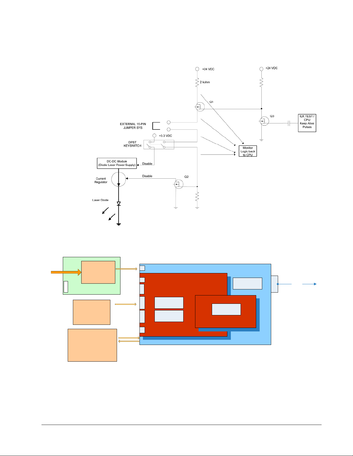
Block Diagrams
)$1
&21752//(5
3&%
$&,13879$&$
+]
,1387
3:5
9'&
86%
&RQQ
6DIHW\
,QWHUORFN
6+877(5
$&,QSXW
*5((1/$6(5
',2'('593&%
&206:
212))
0,&52&21752//(50+]
)3*$0+]
&8,9+%
NK=VZLWFKLQJIUHT
/DVHUGLRGH
&+$66,6
&+,//(5
3&
5625
86%
Block Diagrams
Figure 3-2 Interlock safety block diagram
Figure 3-3 Millennia eV system block diagram
Laser Description 3-7

Block Diagrams
3-8 Laser Description

CHAPTER 4: Controls, Indicators, and
Power
switch
Connections
This chapter describes the user controls, indicators, and connectors of the Millennia eV
laser system. Instructions for operating this system are found in
Laser System Controls
Figure 4-1 shows the rear panel of the laser, which contains all the controls, indicators,
and connectors for this system, except the main emission indicator, which is located on
top of the laser near the output end. These controls are described in
Chapter 7, “Operation.”
Table 4-1.
Figure 4-1 Millennia eV laser head, rear panel
4-1

Laser System Controls
Table 4-1 Laser head rear panel controls
Control Description
Power switch The soft-power switch on the back of the laser interrupts power to the laser CPU. When this
switch is in the OUT position, the laser is considered “off.” No laser emission is possible.
However, there is still some +48 VDC power available inside the control board.
C
AUTION
:
Under ALL conditions, when servicing the laser (such as replacing any PCBs),
it is critical to unplug the external power by removing the AC plug from the wall.
To turn the laser on, depress the power switch. The switch “clicks” into the IN position and
remains there.
When the button is in the IN position, the laser can be turned on. A green lamp on the
button lights, providing confirmation that power is active and the button is in. The CPU is
alive, laser emission is possible, the SHG crystal begins to warm up, and so on.
The power switch has no interaction with the interlock system. It is not necessary to touch
the switch when a fault occurs (such as interlock or overtemperature).
ENABLE keyswitch Closes the interlock when it is set to the ENABLE position. The keyswitch prevents
unauthorized use of the laser when it is turned to the horizontal (off) position and the key is
removed. Placing this switch in the ENABLE position allows the laser to be turned on.
For safety, when the system is not inst alled in the master OEM system, or is not in use, turn
the keyswitch to the horizontal position and remove the key to prevent unauthorized use of
the laser.
Emission indicator (white lamp
on top of the laser, Figure 4-2)
ST ATUS indicator (green/red
lamp on the rear panel)
48 V power connector Attachment for the cable from a 48 VDC utility unit. Spectra-Physics provides this utility unit
Illuminates to indicate that laser emission is present or imminent. This can only happen
after all of the safety requirements are met, the keyswitch is turned to the ENABLE position,
and an appropriate command or analog signal is provided. The indicator remains on during
laser emission and turns off immediately when commanded or the analog signal is
removed.
Flashes amber during the harmonic crystal warm-up sequence. When the unit is warmed
up and all of the safety requirements have been met, the indicator turns green and blinks.
The indicator blinks red to indicate that a fault has occurred.
(PN 90059738) with the system.
4-2 Controls, Indicators, and Connections

Laser System Controls
Emission indicator
(white)
Output
beam port
Table 4-1 Laser head rear panel controls (Continued)
Control Description
ANALOG connector (15-pin,
D-sub, HD, female)
RS-232 connector
(9-pin, D-sub, female)
Attachment for a control cable from an analog control device.
15
11 15
Among its many functions, this connector can be used to provide an interlock to turn off
laser emission in the event that a safety switch is opened unexpectedly. This connector
also provides a STATUS output that can be used to drive an emission indicator. Refer to
Table 4-3 for a complete description of these pins, and to “ANALOG Interface” for
instructions on how to use this connector to control advanced features of the Millennia eV
laser.
NOTE: In order for the laser to turn on, pins 8 and 13 of this connector must be shorted
together, either directly or through a user-supplied, normally closed interlock
switch.
The male mating connector is TYCO/AMP 1658681-1 (housing, RoHS-compliant), using
pins TYCO/AMP 1658686-1 (crimp pin, RoHS-compliant).
Attachment for a serial cable from a control device, such as a personal computer. Refer to
Table 4-2 for a description of these pins.
15
USB input connector
(USB, Type B)
96
Attachment for a type-B USB cable between the control device, such as a personal
computer, and the laser. A USB driver is provided on the GUI USB flash drive that ships
with the system. The USB driver must be installed on the control computer before this port
can be used.
Figure 4-2 Millennia eV laser emission indicator and output b eam
Controls, Indicators, and Connections 4-3

ANALOG Interface
Table 4-2 describes the pins for the RS-232 serial connector.
Table 4-2 IBM-PC/AT serial port pinout
Computer or Terminal Laser Head
RS-232-C Signal Name Signal Pin No. (9-Pin) Pin No. Signal
Transmit data TXD 3 3 RXD
Receive data RXD 2 2 TXD
Signal ground 55
Protective ground SHELL SHELL
ANALOG Interface
The 15-pin HD D-sub ANALOG port (Table 4-3) is used to monitor the laser system via
user-supplied TTL-level signals.
The ANALOG interface is used in conjunction with serial commands executed through
the RS-232 interface. It provides the following features:
Safety interlock
Indicate emission output
Ready and fault indicators
Average power monitor
The configuration and status of the pins of the ANALOG interface are set and queried
using serial commands.
Table 4-3 ANALOG port pin description
Pin Type Description Function
1 Output, analog POWER_OUT When referenced to pin 2, an uncalibrated DC analog signal
proportional to laser output power is provided to the user for
monitoring laser output power. No scale.
2 Ground, analog AGND Ground reference for pin 1.
3 Input, analog RESERVED Leave this pin unconnected.
4 Output, digital TEMP_OK Open drain. Used to indicate that an over-temperature situation
exists. Maximum sink current is 50
mA. Low = Temperat ure is OK
5 Output, digital ILK_FAULT Open drain. Used to indicate that the interlock is OPEN. Maximum
sink current is 50
turn-on).
6 Input, digital RESERVED Leave this pin unconnected.
7 Input, digital RESERVED Leave this pin unconnected.
mA. Low = interlock is OPEN (laser will NOT
4-4 Controls, Indicators, and Connections

Monitoring Laser Status Via the ANALOG Port
Table 4-3 ANALOG port pin description (Continued)
Pin Type Description Function
8 Output, analog ILK_OUT Provided for the attachment of a user interlock switch. The
open-circuit voltage is +24 VDC with 2 k output impedance. Use a
low-impedance external switch to connect this pin back to pin 13 to
complete the interlock circuit. The voltage drop across the external
switch must be <
mA current.
25
9 Output, digital SHUTTER_OPEN Open drain. Used to indicate that the shutter is OPEN. Maximum sink
current is 50 mA. Low = shutter is OPEN (emission hazard is present).
10 Output, digital RESERVED Leave this pin unconnected.
11 Input, digital RESERVED Leave this pin unconnected.
12 Input, digital RESERVED Leave this pin unconnected.
13 Input, digital ILK_RTN Must be connected to pin 8 through a normally closed switch in order
for the laser to turn on.
14 Output, digital EMISSION Open drain. Used to indicate that the laser EMISSION is ON.
Maximum sink current is 50 mA. Low = EMISSION ON.
1 volt, and the switch must be capable of handling
15 Ground, digital DGND Ground reference pin for 4,5,6,7,9,10, and 11.
Monitoring Laser Status Via the ANALOG Port
Using the Indicator Outputs
The following pins can be used to sync LED indicators or TTL logic circuits:
Pin 4 high, over temperature condition
Pin 5 low, interlock fault condition
Pin 9 low, shutter is open
Pin 14 low, laser emission is present
The pin is pulled low through the field effect transistor (FET) shown in Figure 4-3,
which is a schematic of a simple drain circuit used by the ANALOG connector.
Figure 4-3 ANALOG output drain schematic
When the condition corresponding to one of these pins is active, the logic output pulls
low.
Controls, Indicators, and Connections 4-5

Monitoring Laser Status Via the ANALOG Port
Note that pin 15 is the reference digital ground pin on the ANALOG connector and should
be used with pins
4, 5, 9, 10, and 14.
4-6 Controls, Indicators, and Connections

CHAPTER 5: Installation
This section provides detailed instructions and notes for planning for and installing the
Millennia eV laser system. If the user has not set up the laser before, or if is moving the
laser system to a new location, review this section in its entirety before use.
Pre-Installation Check
Required Tools
The following items are required in order to install the system:
Cleanroom-grade gloves
3/32 in. and 3/16 in. Allen wrenches
6 mm Allen wrench
Power meter or beam dump
Safety goggles for 532 and 1064 nm wavelengths
Personal computer running Windows XP or later
DB-9 male to DB-9 female serial cable or
type A/B USB cable
Be sure to follow all safety precautions for laser use while handling or storing the laser
system. Be sure to install all laser safety devices before using the laser. Refer to
Chapter 2, “Laser Safety,” for more information.
Utility Requirements
Millennia eV laser systems require 100-240 VAC electrical service. The chiller has its
own electrical requirements. Consult the chiller manual for this information.
The Millennia eV system introduces up to 100 W (341 BTUH) of heat into the room
(excluding chiller power). Provide enough room cooling capacity to remove this waste
heat to prevent the system from overheating.
Newport P/N 818P-050-17W, Newport power m eter P/N 1918-R
or 1917-R, and detector P/N 818P-050-50W are recommended.
5-1

Mounting the Laser Head
Utility unit
connection
Chilled water
connection: In
Host serial control
Host analog/TTL
system control
Chilled water
connection: Out
Mounting the Laser Head
Following standard practice, mount the laser head on a suitable flat surface.
Carefully remove the laser head from the Mylar bag
and set it on the table. DO NOT DROP the laser head
onto the table.
1. Select either three 1/4-20 (SAE) or three M6 metric Allen screws.
2. Insert the center Allen screw with flat washer into the laser head, and align the laser
to the table or plate.
3. Secure the center bolt but do not tighten until all bolts have been installed.
4. Install the front two bolts with flat washers.
5. Tighten the three mounting bolts and torque them to 0.25 N*m (2.25 in-lb).
Refer to “Outline Drawings” for dimensions and hole locations.
Connecting the System
Figure 5-1 shows how the Millennia eV laser system is connected to the host controller,
utility unit, and chiller.
Figure 5-1 System interconnect drawing
5-2 Installation

Installing the Chiller
1. Attach two hoses between the chiller and the WATER IN and WATER OUT connectors.
Hoses are provided with Spectra-Physics chillers; hose fittings are supplied when a
user-supplied chiller is used.
2. If analog control is to be used, attach a user-supplied analog cable between the host
system and the
3. Attach either type A/B USB cable from the host system to the USB port
(Spectra-Physics highly recommends using the
from the host system to the RS-232 port.
4. Attach the DC power cable from the utility unit to the 48V connector, but do not
connect the utility unit AC input at this time.
5. Install the ENABLE key.
ANALOG connector (see “Analog Control Considerations”).
USB port) OR a standard serial cable
AC Power Considerations
The unit is provided with a grounded appliance inlet. To help maintain the safety of the
equipment, it must be connected to a grounded connection. The ground should be
verified prior to use.
Access to the power connection cord should be maintained to allow the unit to be
disconnected from power in the event of an emergency.
Analog Control Considerations
If analog signals are to be used to control the laser, the user must make a cable that
attaches between the analog port of the host controller and the
laser head.
Installing the Chiller
General Information
The Millennia eV system requires a chiller that meets the requirements shown in
Table 3-1.
ANALOG connector on the
If analog control is not to be used, pins 8 and 13 of the ANALOG
connector must be shorted together (preferably through a safety
switch) in order for the laser to operate. For installation and test
purposes, a shorting jumper plug is provided.
Spectra-Physics offers a chiller that is suitable for use with the Millennia eV laser
system. If the user ordered the chiller from the factory with the laser, it meets these
requirements. For specific information about the chiller shipped with the system,
consult the chiller manual included with the system.
Installation 5-3

Installing the Chiller
If the user did not order the chiller from Spectra-Physics, make sure that it meets the
requirements in
Table 3-1. Spectra-Physics highly recommends speaking with one of
our representatives about the chiller’s design and capabilities.
Use distilled water only! The use of improper coolant in the
laser can cause irreparable damage to the laser which would
not be covered by the warranty. Be certain of the coolant and
chiller specifications prior to using any non-factory chiller with
this laser.
Installation
1. Consult the chiller’s user manual and follow the manufacturer’s suggested
operation requirements.
2. Verify that the local voltage and line frequency are within the acceptable input range
for the specific chiller.
3. Set the chiller on the floor or mount it close enough to the Millennia eV system so
that the cooling hoses reach the laser head without strain.
Position the chiller so that the warm air exhausted from
it is not drawn back into itself. Allowing it to do so could
affect the stability of the chiller and, therefore, the
laser.
Do not place the chiller directly above the laser or utility
unit. If a leak or condensation ever developed in the
chiller, dripping water could damage the unit below it
and constitute a safety risk.
4. Connect the coolant hoses between the laser head and chiller.
The direction of coolant flow is important for proper operation of the laser system. The
coolant connectors on the laser head are polarized (
Figure 5-1) to prevent incorrect
connection at the laser head. If the chiller was ordered from Spectra-Physics, the hoses
and the connections on the chiller are already set for proper water flow direction.
However, if the chiller was ordered elsewhere, make sure the hoses are assembled with
the correct fittings to allow water to flow in the proper direction.
If it is necessary to release the hose connections, shut off the laser and chiller first, then
disconnect the hoses. On chillers provided by Spectra-Physics, when the hoses are
released, the hoses separate slightly from the connections and self-seals under spring
pressure.
NEVER remove a hose while the chiller is operating, and never
operate the chiller with the hoses disconnected.
5. Fill the chiller reservoir with distilled water and turn on the chiller. As the fluid in
the reservoir drops, continue to fill it with distilled water until it no longer drops.
5-4 Installation

Installing the Chiller
6. Verify that there are no water leaks from the chiller, the hoses or the laser.
Make
sure the reservoir does not empty!
7. Fill the reservoir with new distilled water and run the chiller until no more bubbles
appear. Top off the reservoir when necessary.
8. Verify that the chiller is set to 20°C.
If the chiller was ordered from Spectra-Physics, it was pre-set at the factory to
operate at 20°C.
If the chiller was not purchased from Spectra-Physics, refer to the chiller’s user
manual for instructions on how to set the temperature.
9. Turn off the chiller.
The system is now ready for use. Remove any protective covering from the laser’s
output window, and place a suitable power detector or beam dump in front of the laser
output exit port.
Installation 5-5

Installing the Chiller
5-6 Installation

CHAPTER 6: Preparing for Operation
Installing the USB Driver and User GUI Software
The Millennia eV system can be controlled using the Millennia eV graphical user
interface (GUI) control software that is included with the system, or it can be controlled
by sending commands one at a time using the Communication window in the GUI
control program. Installation instructions for the Millennia eV control software are
given in the next section.
The GUI control software is provided on a USB memory stick along with the USB
driver. The following two sections provide directions for installing this software.
To run the GUI control software, the control computer must meet these minimum
requirements
Intel or AMD 32- or 64-bit, single or multi-core processor with > 1 GHz clock speed
1 GB RAM
100 MB available disk space for installation
Mouse or other Windows-compatible pointing device
Video display with 1366 x 768 (SVGA) or higher resolution
Available USB or RS-232 serial port
Microsoft Windows XP, Vista, or 7 operating system
A type A/B USB cable (preferred) or a standard 9-pin serial cable can be used for
communication between the host computer and the laser system.
Installing the Millennia eV USB Driver
NOTE: If the USB connection is to be used, the Millennia eV USB driver must be
installed before connecting the USB cable or turning on the laser. No driver
software is necessary when the
connection is to be used, skip to
Software.”
This section describes how to install the USB driver software. This driver is located on
the USB flash drive packed in the accessory kit.
To install the USB driver software:
1. Place the USB memory stick containing the Millennia eV software in an available
USB port.
2. Browse to the Millennia eV USB Driver folder on the memory stick and open it.
3. Double-click the VCP_V1.3.1_Setup icon.
SERIAL COM port is used. If an RS-232 serial
“Installing Millennia eV GUI Control
6-1

Installing the USB Driver and User GUI Software
Figure 6-1 Setup icon
4. Wait for the installation process to initialize.
Figure 6-2 Preparing to Install window
5. When the InstallShield wizard opens, click Next.
6-2 Preparing for Operation

Installing the USB Driver and User GUI Software
Figure 6-3 InstallShield wizard
6. Wait for the Setup process to finish.
Figure 6-4 Setup Status window
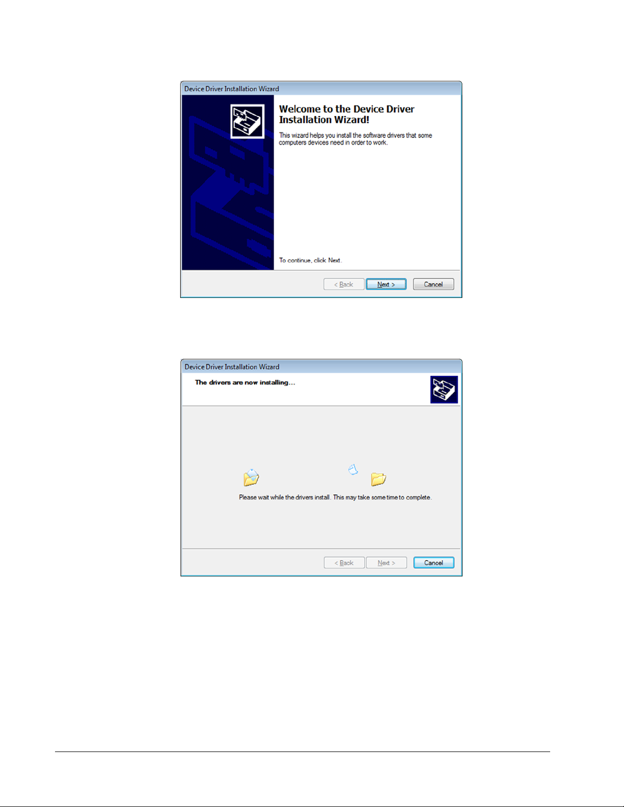
7. In the Device Driver Installation wizard, click Next.
Preparing for Operation 6-3
Installing the USB Driver and User GUI Software
Figure 6-5 Device Driver Installation wizard
8. Wait for the drivers to install, and then click Next.
Figure 6-6 Driver installation in progress
9. When the Completing the Device Driver Installation window opens, click Finish.
6-4 Preparing for Operation

Installing the USB Driver and User GUI Software
Figure 6-7 Completing the Device Driver Installation window
10. Attach the provided USB cable from the Millennia eV laser head to the control
computer, and power on the Millennia eV laser head by depressing the Power switch
in the rear panel to the IN position.
An Installing device driver software message appears.
11. When the driver is successfully installed, a message appears in the taskbar similar
to the one shown below.
Figure 6-8 Software installed successfully message
The Millennia eV USB driver installation is now complete.
12. Turn off the Millennia eV laser head.
Installing Millennia eV GUI Control Software
The Millennia eV GUI control software provides an easy way to monitor and control the
laser system. System operation and a complete explanation of the GUI control software
is described in
Chapter 7, “Operation.” To install the GUI control software:
1. Place the Millennia eV USB memory stick in an available USB port.
2. Browse to the Millennia eV USB Driver folder on the memory stick and open it.
3. Double-click the Setup icon (or setup.exe) and follow any prompts that appear
during installation.
Preparing for Operation 6-5

Installing the USB Driver and User GUI Software
Figure 6-9 Setup file
4. If the computer does not have .NET Framework installed, the following window
opens. Click Accept.
Figure 6-10 .NET license agreement
5. Wait for the Microsoft .NET Framework installation process to complete.
Figure 6-11 .NET installation progr ess
6. When .NET Framework installation is complete, the Welcome to the
Spectra-Physics Setup Wizard window opens. Click Next.
6-6 Preparing for Operation

Installing the USB Driver and User GUI Software
Figure 6-12 Welcome window
7. Select the installation folder. The software creates the directory
C:\Program Files\Spectra-Physics\Spectra-Physics (this is the default
location but the user can change the directory if needed by clicking Browse), and
installs itself in that folder. Click Next.
Figure 6-13 Select installation folder
8. In the Confirm Installation window, click Next.
Preparing for Operation 6-7

Installing the USB Driver and User GUI Software
Figure 6-14 Confirm installation window
9. Wait for the Spectra-Physics installation process to complete.
Figure 6-15 Installing window
10. When the Installation Complete window opens, click Close.
6-8 Preparing for Operation

Installing the USB Driver and User GUI Software
Figure 6-16 Installation Complete window
11. The software places a Spectra-Physics icon on the desktop. When ready to start
operation, double-click the desktop icon to start the control software.
Figure 6-17 Spectra-Physics desktop icon
Preparing for Operation 6-9

Installing the USB Driver and User GUI Software
6-10 Preparing for Operation
CHAPTER 7: Operation
This chapter illustrates the day-to-day operation of the Millennia eV laser system using
both the Millennia eV GUI menus and serial commands and queries. The commands and
queries can be issued in the Millennia eV GUI Communication window or using a
user-designed program. A full list of commands and queries is provided in
“Programming Reference Guide.”
The Spectra-Physics Millennia eV laser is a
Class
definition, a safety and fire hazard. T ake precautions to
prevent accidental exposure to both direct and
reflected beams. Diffuse as well as specular beam
reflections can cause severe eye or skin damage.
Residual light at 1064
present.
The procedures in this chapter assume that the Millennia eV laser has been installed by
a Spectra-Physics trained service technician, or by the user according to the instructions
in
Chapter 5, “Installation” and Chapter 6, “Preparing for Operation.” This means that
the following tasks are completed:
Appendix A,
IV — High-Power Laser whose beam is, by
nm wavelength might also be
The chiller is installed properly, filled with distilled water, and set to 20°C.
The 48 VDC power cord from the utility unit is attached to the 48 V connector in
the rear of the laser head (do not plug the AC power cord to the DC utility unit at
this time).
If installed, the interlock relay and emission circuits are properly wired, or the
provided jumper plug is temporarily installed on the
The Millennia eV graphic user interface (GUI) is installed in the host computer and
ANALOG port.
the laser head is connected to the host computer via either the USB cable or the
serial cable.
If the user is uncertain about the status of the laser, refer to Chapter 4, “Controls,
Indicators, and Connections,” and verify that it has been connected correctly.
7-1

Millennia eV GUI Menus
Millennia eV GUI Menus
This section describes the controls and indicators that are shown in the Millennia eV
GUI screen.
The Main Menu
The laser operator can monitor all laser conditions from this menu. All the basic laser
operations can be also performed from this menu. There are four boxes that are either
main controls or main indicators, described in
Table 7-1.
Figure 7-1 Main menu
7-2 Operation

Millennia eV GUI Menus
Table 7-1 Main menu features
Feature Description
Laser ON/OFF box Emission Indicator: Turns bright green when the laser is on and
turns dark green when the laser is off.
ON/OFF Toggle Switch: Toggles the laser emission on and off. To
turn on laser emission, flip this switch to ON, then click the OK button
that appears on the pop-up menu. The laser turns on in 3 seconds
and the Emission Indicator turns bright green to indicate that
emission is present.
System Statu s box System Status Indicator: Displays the present system status and
also displays any fault that occurs. This indicator is orange if the laser
is warming up when power is first applied. It turns red when a fault
exists. It turns bright green when all faults are cleared. The laser is
ready to turn on when this System Status Indicator is bright green.
Shutter box Shutter Indicator: T urns bright green when the shutter is open and
turns dark green when the shutter is closed.
Open/Close Toggle Switch: Opens or closes the laser output
shutter.
The View Button
Output Power box Laser Power Input Box: Type numbers into this box to set up the
desired laser output power and press Enter to send the new power
setting to the system. Click the up or down arrow to change the set
power by 0.1W increment.
Laser Power Indicator: Displays laser output power in watts. This is
the numerical version of what is displayed on the laser power gauge.
Laser Power Gauge: Displays the laser output power.
View button Opens a list of three sub-menus. See “The View Button.”
There are three other menus that the user can access under the View button. Click the
View button to open the menu list shown in
Figure 7-2.
Figure 7-2 View menu
Operation 7-3

Millennia eV GUI Menus
The Communication Window
Clicking Communication in the View menu opens the Communication window. This
is a terminal window that provides an alternative to sending and receiving commands.
Appendix A, “Programming Reference Guide,” contains a list of all serial commands
and queries.
Figure 7-3 Communication window
The indicators and controls in the Communication window are described in Table 7-2.
Table 7-2 Communication window features
Feature Description
Send command input line Type a serial command in the white blank line on top and press
Enter to send the command to the system.
Clear Command After Send
check box
Send pane Commands sent to the system are shown in the Send pane on
Received pane System responses are returned in the Received pane on the
Clear button Press Clear to clear all commands shown in the Send pane as
Close button Press Close to close the Communication window.
If this box is checked, the command input line is cleared after the
command is sent to the system. If this box is unchecked, the
command remains in the input line after the command is sent to
the system.
the left. The most recent command is shown at the top.
right. The most recent response is shown at the top.
well as all system responses shown in the Received pane.
7-4 Operation

Millennia eV GUI Menus
The SHG Oven Window
Clicking SHG Oven in the View menu opens the Oven window. This window allows
the user to optimize the SHG crystal temperature.
Figure 7-4 Oven window
The indicators and controls in the Oven window are described in Ta ble 7-3.
Table 7-3 SHG Oven window features
Feature Description
Start Autotune button Press Start Autotune to start the SHG temperature tuning
process.
Stop Autotune button Press Stop Autotune to stop the SHG temperature tuning
process.
SHG tuning progress
gauge
SHG tuning progress
indicator
Displays the SHG autotune progress. The green bar all the way to
the right means that the SHG temperature tuning process is
complete.
Displays the SHG autotune progress in percent. 100% means
that the SHG temperature tuning process is complete. This is the
numerical version of what is displayed on the SHG tuning
progress gauge.
Operation 7-5

Start-up Sequence
The About Window
Clicking About in the View menu opens the About window. This window shows the
laser model, the firmware version, the FPGA version, and the software GUI version.
This is for checking information only. Clicking the OK button brings the GUI back to
the main menu.
Figure 7-5 About menu
Start-up Sequence
1. Turn on the chiller.
2. Connect the AC power cord to the DC utility unit.
3. Depress the Power switch , located on the rear of the laser head, and wait for
the green lamp on this switch to light.
4. Wait 1-2 seconds for the ST ATUS lamp on the rear of the laser to begin to flash
(green/yellow), indicating that the laser CPU is running and the SHG crystal is
warming up.
7-6 Operation

Start-up Sequence
5. Verify the USB or RS-232 connection to the laser, then turn on the control computer
and start the Millennia eV GUI software program.
6. Wait for the GUI to connect.
Figure 7-6 GUI connection in progress
7. If the connection is successful, the GUI goes to the main menu automatically. This
initialization process takes several seconds to complete. If the connection between
the GUI and the laser head is not established correctly, the GUI remains in the
“connecting” state. In this case, close the GUI and redo steps 1-6.
8. Note that if any interlock conditions exist, the light indicator in the System Status is
red and also the fault description is displayed.
9. Verify that the key is in the ENABLE (vertical) position and that all interlocks are
closed. If there are no faults present, the System Status indicator is bright green and
System Ready is displayed.
The system is now ready for use. Carefully read the rest of this section for detailed
operational instructions.
Operation 7-7

Operating the Laser
Operating the Laser
Turning the Laser On and Off
If the System Status indicator is green, the user can turn the laser on by clicking the
Emission
deactivated and the user cannot turn on the laser until all faults are cleared. When the
ON/OFF toggle switch is flipped to ON, a safety warning message appears.
Figure 7-7 Laser turning on notice
This safety warning requires the user to click OK to proceed. When OK is clicked, the
white laser emission indicator on the laser cover turns on immediately and emission
begins after a safety delay of about 3 seconds. This second authorization allows the user
to cancel the turn-on request (by pressing Cancel) if the Emission
was pressed by mistake. When the laser turns on, it returns to the last power setting
previously operated at. The laser output power setting can be changed by typing the
desired output power (for example, 20 or 25) in the Laser Power Input box and pressing
Enter. Clicking the up or down arrow changes the set power in 0.1 W increments.
Actual power output is displayed on both the power gauge in the Output Power and as
a number just above the gauge.
ON/OFF toggle switch to ON. If any faults exist, the ON/OFF toggle switch is
ON/OFF toggle switch
To turn off the laser, click the Emission ON/OFF toggle switch to OFF. Laser emission
stops immediately and turns off the white laser emission indicator on the laser cover.
NOTE: When the laser is turned on, the diode current slowly ramps up from the zero
current to the operating curr ent. It takes a few minutes for the laser to r each the
set power level.
Shutter Control
When the laser is on and operating at the desired output power, the user can open the
output shutter to allow the laser output beam to come out of the laser head. The output
shutter can be closed to prevent the laser beam from coming out of the laser head while
the laser emission is still on and operating normally. It is also possible to open or close
the shutter while the laser emission is off, which means that the user can open the shutter
first and turn the laser on later. If the shutter is open while the laser emission is on,
turning the laser emission off also closes the shutter.
NOTE: Always verify that the laser output beam would be properly terminated before
opening the shutter.
7-8 Operation

Operating the Laser
Using Serial Commands
The Communication window can be also used to send and receive commands via a
separate terminal. Refer to
“Programming Reference Guide,” for information about using serial commands and
queries.
“The Communication Window” and Appendix A,
SHG Autotune
The second harmonic generator (SHG) crystal needs to be maintained at the appropriate
phase-matching temperature to keep the 532
phase-matching condition is changed over time, the SHG crystal temperature needs to
be re-optimized. The user can optimize the SHG temperature using the Autotune
function in the SHG Oven window. Refer to
descriptions.
When the SHG temperature autotune process is started, the shutter is closed
automatically and it remains closed during the process. The autotune process takes
about 15-20 minutes to complete and the user needs to open the shutter to access the
laser beam after the SHG autotune process is complete. If the SHG autotune is stopped
prior to the completion, the SHG temperature goes back to the previous temperature
setting point.
nm output power optimized. If the SHG
“The SHG Oven Window” for control
NOTE: When the laser is installed for the first time and turned on, the system should
operate normally and properly. However, it is recommended that the user
“autotune” the SHG temperature at the first turn on after the installation to
ensure the SHG temperature is optimized.
Alignment Mode Operation
When the Millennia eV output beam needs to be guided for the first time to the user set
up or to another laser that will be pumped by the Millennia eV laser, the user should use
the minimum amount of green output beam (barely above the threshold level) for the
alignment. The lowest amount of the green output power that the user can get under the
normal operating condition (power mode) is typically higher than the threshold level
power. To achieve the threshold level output beam, the system needs to be temporarily
operated in the current mode, which can be done by sending commands and queries in
the Communication window.
To operate the Millennia eV laser at the threshold level in the current mode:
1. Make sure that the laser is off.
2. Open the Communication window.
3. Switch the system to the current mode by sending M:0 command.
4. Verify that the laser is in the current mode by sending ?M command. The response
should be 0 (current mode). If not, redo step 3 and verify again until 0 is received.
5. Set the diode current to 2A by sending C:2 command.
Operation 7-9

Operating the Laser
6. Verify that the current is set to 2A by sending ?CS command. The response should
be 2. If not, redo step 5 and verify again until 2 is received.
7. Turn on the laser (Main Menu control). It should reach 2A within about a minute of
turning on the laser.
8. Open the shutter (Main Menu control) and align the Millennia eV output beam as
needed. Verify that the green beam is contained and terminated properly in the set
up.
9. When the alignment is done, close the shutter (Main Menu control) and turn off the
laser (Main Menu control).
10. Go back to the power mode by sending M:1 command.
11. Verify that the laser is in the power mode by sending ?M command. The response
should be 1 (power mode). If not, redo step 10 and verify again until 1 is received.
12. Close the Communication window.
The Millennia eV laser is now ready to be used in the normal operation mode.
7-10 Operation

CHAPTER 8: Maintenance
This chapter provides information on how to maintain the Millennia eV laser system and
how to diagnose problems should any occur.
The Spectra-Physics Millennia eV laser is a
Class
IV — High-Power Laser whose beam is, by
definition, a safety and fire hazard. T ake precautions to
prevent accidental exposure to both direct and
reflected beams. Diffuse as well as specular beam
reflections can cause severe eye or skin damage.
Residual light at 1064
present.
Never open the Millennia eV laser cavity. To retain a clean
intracavity environment, all components have been cleaned to
stringent standards prior to assembly in a clean room and have
been permanently aligned at the factory. Removing the laser
cavity cover compromises the cleanliness of the intracavity
space and voids the warranty. There are no user-serviceable
parts inside the laser head
nm wavelength can also be
.
Flushing and Refilling the Chiller
Basic instructions are provided in this manual for maintaining the chiller. For complete
information about the unit or for further instructions, refer to the chiller manufacturer’s
user manual that came with the chiller.
From time to time it is necessary to check the level of the coolant or to change the
coolant.
Maintenance Tips
Check the coolant level regularly.
For any long-term storage, drain the coolant in the reservoir, the hoses, and the laser.
Clean the exterior of the chiller with a soft cloth and warm, soapy water. Never use
abrasive or solvent-based cleaners.
Do not immerse the chiller! Also keep coolant and water away from the vents and
the power switch.
Replacing the Coolant
Refer to the chiller manual for instructions.
8-1

Diagnostics and Troubleshooting
Diagnostics and Troubleshooting
This diagnostics guide is intended to assist in identifying some of the problems that can
arise while using the laser. Use this information to diagnose and perform corrective
action on laser system issues.
If there is a problem with the Millennia eV laser that the user
cannot resolve after using this basic diagnostics section, cont act
a Spectra-Physics service representative for further assistance.
Contact information for service cen ters is provided in
“Customer Service.”
System Event Codes
Event codes are generated by the system in response to various events. Table 8-1
contains the following information:
Event Code: The number the system responds with after receiving query ?FH
Event Description: Brief explanation of the event.
Event T ype: Notification, indication, or fault. Some codes can be considered either
faults or indications. Indicators might or might not be reported.
Notification: Events that occur during normal operation
Indication: Unusual events that can require immediate action to correct.
Fault: Unusual events that cause the diodes to turn off immediately
Action Required: A list of actions to perform in response to this event code
Chapter 9,
Table 8-1 System event codes
Event
Code
000 System OK System ready None.
011 Internal interlock open Shut down Verify that there is no short circuit to ground on external
012 Analog interlock open Shut down Verify that the analog connector is installed. Verify that
013 Keyswitch interlock open Shut down Verify that the keyswitch is in the ENABLE position.
020 FPGA not responding Shut down Contact Spectra-Physics service representative.
031 Laser diode under temperature
033 Laser diode over temperature
066 Watchdog expired Shut down Reset power to the unit. Reset communications.
135 SHG hardware fault Shut down Contact Spectra-Physics service representative.
Event Description Event Type Action Required
interlocks. Contact Spectra-Physics service
representative.
pins 8 and 13 are connected together.
Shut down Verify that the chiller is set to 20°C.
15°C)
(<
Shut down Verify that the chiller is on. Verify that it is set to 20°C.
35°C)
(>
Verify that the chiller has proper flow.
8-2 Maintenance

Diagnostics and Troubleshooting
Table 8-2 Non-event faults
Event Description Action Required
Laser does not power on Check that all cables are securely connected.
Verify that input voltage is 48 VDC ± 2 V.
Laser head temperature is outside the
operating range
Laser is not warmed up Allow the laser to warm up for at least 20 minutes.
Measured power is lower than monitor Check if the output window is dirty or damaged.
High optical noise Check the laser is running at its specified output power.
Bad mode Laser is not warmed up. Allow the laser to warm up for at least 20 minutes.
Allow the laser to warm up for at least 20 minutes.
External noise source exists. Check that there are no strong
electromagnetic noise sources near the laser. Check that there are no high
mechanical vibrations coupled onto the laser head from the mounting
surface.
Check if the output window is dirty or damaged.
Troubleshooting Guide
The following table describes possible situations that can be resolved by the user.
Table 8-3 Troubleshooting guide
Symptom Possible Causes Corrective Action
No laser beam; laser does
not power on
Low power Laser is not warmed up Allow the laser to warm up for at least 20
High optical noise Laser head temperature is outside the
Loose power cable connector Check that all cables are securely connected.
Improper DC voltage Verify that input voltage is 48 VDC ± 2 V.
minutes.
Dirty output window Clean the laser head output window.
Verify that the chiller has good flow and is set
operating range
External noise source exists Check that there are no strong
Laser is running below its specified output
power
to 20°C.
electromagnetic noise sources near the laser.
Check that there are no high mechanical
vibrations coupled onto the laser head from
the mounting surface.
Check the laser output power and verify that
the laser is running at the specified output
power level.
Maintenance 8-3

Diagnostics and Troubleshooting
Table 8-3 Troubleshooting guide (Continued)
Symptom Possible Causes Corrective Action
Bad transverse mode Laser is not warmed up Allow the laser to warm up for at least 20
minutes.
Output window is dirty Clean the laser head output window.
Nonlinear crystals have reached end of life Contact a Spectra-Physics service
representative.
8-4 Maintenance

CHAPTER 9: Customer Service
Warranty
This warranty supplements the warranty contained in the specific sales order. In the
event of a conflict between documents, the terms and conditions of the sales order shall
prevail.
Unless otherwise specified, all parts and assemblies manufactured by Spectra-Physics are
unconditionally warranted to be free of defects in workmanship and materials for a
period of one year following delivery of the equipment to the F.O.B. point.
Liability under this warranty is limited to repairing, replacing, or giving credit for the
purchase price of any equipment that proves defective during the warranty period,
provided prior authorization for such return has been given by an authorized
representative of Spectra-Physics. Spectra-Physics provides at its expense all parts and
labor and one-way return shipping of the defective part or instrument (if required).
In-warranty repaired or replaced equipment is warranted only for the remaining portion
of the original warranty period applicable to the repaired or replaced equipment.
This warranty does not apply to any instrument or component not manufactured by
Spectra-Physics. When products manufactured by others are included in
Spectra-Physics equipment, the original manufacturer’s warranty is extended to
Spectra-Physics customers. When products manufactured by others are used in
conjunction with Spectra-Physics equipment, this warranty is extended only to the
equipment manufactured by Spectra-Physics.
This warranty also does not apply to equipment or components that, upon inspection by
Spectra-Physics, are shown to be defective or unworkable due to abuse, mishandling,
misuse, alteration, negligence, improper installation, unauthorized modification,
damage in transit, or other causes beyond the control of Spectra-Physics.
This warranty is in lieu of all other warranties, expressed or implied, and does not cover
incidental or consequential loss.
The above warranty is valid for units purchased and used in the United States only.
Products shipped outside the United States are subject to a warranty surcharge.
Contacting Customer Service
Thank you for your purchase of Spectra-Physics instruments!
At Spectra-Physics, we take great pride in the reliability of our products. Considerable
emphasis has been placed on controlled manufacturing methods and quality control
throughout the manufacturing process. Nevertheless, even the finest precision
instruments need occasional service. We feel our instruments have excellent service
records compared to competitive products, and we hope to demonstrate, in the long run,
9-1

Return Policy and Instructions
that we provide excellent service to our customers in two ways: first by providing the
best equipment for the money, and second, by offering service facilities that get the
instrument repaired and returned as soon as possible.
Spectra-Physics maintains major service centers in the United States, Europe, and
Japan. Additionally, there are field service offices in major United States cities. When
calling for service inside the United States, dial our toll free number: 1 (800) 456-2552.
To phone for service in other countries, refer to
Order replacement parts directly from Spectra-Physics. For ordering or shipping
instructions, or for assistance of any kind, contact the nearest sales office or service
center. Have the instrument model and serial numbers available when calling. Service
data or shipping instructions are promptly supplied.
To order optional items or other system components, or for general sales assistance, dial
1 (800) SPL-LASER in the United States, or 1
“Service Centers.”
(408) 980-4300 from anywhere else.
Return Policy and Instructions
Please note that all products returned to our factory require a Return Authorization (RA)
number. Products returned without this number risk being sent back to without repair.
When contacting a local Spectra-Physics service representative for an RA number, have
ready the model number, serial numbers, user contact information, and a brief
description of the fault.
To return the units to Spectra-Physics for service, repair, or upgrade, use the original
crates and packing material to repack the units. Spectra-Physics encourages the use of
the original crates and packing material to secure instruments during shipment. If
shipping crates, boxes, or packing material are lost or destroyed, we recommend
ordering new ones. Contact Spectra-Physics to order new crates, boxes, or other packing
materials. The user is responsible for one-way shipment of the defective part or
instrument to Spectra-Physics.
The user can also contact the nearest Spectra-Physics field sales office, service center,
or local distributor for an on-site service appointment.
Service Programs
The Millennia eV laser is designed for hands-off operation, and does not require daily
alignment or a routine cleaning of cavity optics. With the exception of the laser output
window, servicing components is generally limited to replacing the entire laser head.
For information concerning the repair of the unit by Spectra-Physics, please call a local
service representative. A list of world-wide service sites is included in the next section,
“Service Centers.” Before calling, note the serial numbers of the laser.
9-2 Customer Service

Service Centers
The replacement of internal Millennia eV system components
must only be performed by personnel trained in these specific
procedures by Spectra-Physics. Do not attempt to replace an
internal system component. Unauthorized repair voids the
warranty.
Service Centers
Table 9-1 Service centers
Location Contact Details
China Newport Beijing Representative Office
Room 2305 Building B Tri-Tower
No. 66 Zhong Guan Cun East Road
Beijing 100080
China
Telephone: +86-10-6267-0065
Fax: +86-10-6267-2342
Email: zhenyi.yao@spectra-physics.com
France Micro-Controle Spectra-Physics S.A.
1, rue Jules Guesde - Bât. B
ZI. Bois de l’Epine - BP189
91006 Évry CEDEX, France
Telephone: +33-1-60-91-68-68
Fax: +33-1-60-91-68-69
E-mail: france@newport.com
Germany and Export Countries
(includes all European and Middle Eastern
countries not listed here)
Japan (East) Spectra-Physics K.K.
Newport Spectra-Physics GmbH
Guerickeweg 7
D-64291 Darmstadt
Germany
Telephone: +49-(0) 6151-708-0
Fax: +49-(0) 6151-708-952
E-mail: germany@newport.com
4-6-1 Nakameguro, Meguro-ku
Tokyo 153-0061
Japan
Telephone: +81-3-3794-5511
Fax: +81-3-3794-5510
E-mail: spectra-physics@splasers.co.jp
Customer Service 9-3

Service Centers
Table 9-1 Service centers (Continued)
Location Contact Details
Japan (West) Spectra-Physics K.K.
Nishi-Honmachi Solar Building, 3-1-43 Nishi-Honmachi, Nishi-ku
Osaka 550-0005
Japan
Telephone: +81-6-4390-6770
Fax: +81-6-4390-2760
E-mail: spectra-physics@splasers.co.jp
Netherlands Newport Spectra-Physics BV
Vechtensteinlaan 12-16
3555 XS Utrecht
Netherlands
Telephone: +31-30-659-21-11
Fax: +31-30-659-21-20
E-mail: netherlands@newport.com
Singapore Newport Opto-Electronics Technologies Private Ltd.
10 Ang Mo Kio Street 65
02-11 TechPoint
Singapore 569059
Republic of Singapore
Telephone: +65-6664-0400
Fax: +65-6664-0401
Email: sales.sg@newport.com
Taiwan Newport Corporation
Room A, 10F, No.80, Sec. 1, Jianguo N. Rd.
Taipai 104
Taiwan
Telephone: +886-2-2508-4977
Fax: +886-2-2508-0367
E-mail: sales@newport.com.tw
9-4 Customer Service

Service Centers
Table 9-1 Service centers (Continued)
Location Contact Details
United Kingdom Newport Spectra-Physics Ltd.
Unit 7, Library Avenue, Harwell Oxford
Didcot, Oxfordshire, OX11 0SG
UK
Telephone: +44 (0) 1235 432 710
Fax: +44 (0) 1235 821 045
E-mail: uk@newport.com
United States and Export Countries
(includes all non-European or Middle Eastern
countries not listed here)
Spectra-Physics
3635 Peterson Way
Santa Clara, CA 95054
Telephone: (800) 456-2552 (Service) or
(800) SPL-LASER (Sales) or
(800) 775-5273 (Sales) or
(408) 980-4300 (Operator)
Fax: (408) 980-6923
E-mail: service@spectra-physics.com
sales@spectra-physics.com
Website: www.spectra-physics.com
Customer Service 9-5

Service Centers
9-6 Customer Service

APPENDIX A: Programming Reference
Guide
Conventions
The user can issue commands and create programs for operating the Millennia eV
system using the Standard Commands for Programmable Instruments (SCPI) serial
command and query language described on the next few pages.
A line of text sent to the Millennia eV system
The Millennia eV system response
<n> An integer parameter
<f> A floating-point parameter
<s> A string
<CR> The ASCII carriage return character (hex 0x0D)
<LF> The ASCII line feed character (hex 0x0A)
Terminate commands to the Millennia eV laser with <CR>. Responses from the laser are
always terminated with
<CR> or <LF>. For more on command and reply syntax, see
“ECHO:<n> ECHO Set/Query Termination Character.”
Commands are not case-sensitive. For example, for the query ?BAUDRATE, the
Millennia eV system would consider any of these inputs to be equivalent:
?BAUDRATE All upper case is OK
?baudrate All lowe r case is OK
?BAUDrate Mixed case is also acceptable
All manual examples illustrate typical Millennia eV parameter settings.
The following abbreviations are used:
INTn Signed integer, n bit minimum size
UINTn Unsigned integer, n bit minimum size
STRn Character string, n bytes long, null-terminated on input
FLOATn Floatinf point number, n digits after the decimal point
<n> Integer parameter
<f> Floating-p oint numbe r
<str> String or character, null-terminated
<sp> Whitespace character (0x20); when used as a delimiter , may usually be
substituted with a colon
A-1

Basic Commands
Basic Commands
The most common commands are listed in this section, such as turning the laser on and
off, opening and closing the shutter, commanding diode current, and verifying system
output power.
C1:<f> or C:<f>
?C1:<f> or ?C<f> Set Diode Current
Range: 0.00 ≤ f ≤ DCL
This command sets the laser diode drive current (amps). This value is stored in PCB
flash memory. Values that exceed the laser diode current limit (DCL) are ignored.
The query returns the measured diode drive current, which is typically slightly different
than the commanded value when the laser is operating. The measured value is near zero
whenever the laser is off.
Example:
C1:9.30 <CR> Set laser diode drive current to 9.30A.
?C <CR> What is the laser diode drive current?
9.25 <CR><LF> The laser diode drive current is 9.25A.
See also ?CS1 or ?CS Query Diode Current.
?CS1 or ?CS Query Diode Current
Range: 0.00 ≤ f ≤ DCL
Default = 1.00
A-2
This query returns the last commanded laser diode current (in amps).
Example:
?CS1 <CR> What is the last commanded current setting for the laser
diode?
9.30 <CR><LF> The last commanded current setting was 9.30A.
?D Query Diode Emission State
Range: 0 (off), 1 (on)
This query returns the present state of laser diode emission (as a string).
Example:
?D<CR> What is the on/off status of diode emission?
1<CR><LF> Diode emission in on.

Basic Commands
?F Query System Status
This query returns the current system status as an ASCII string.
Example:
?F <CR> What is the current laser head status?
SYSTEM OK <CR><LF> or The system is OK.
KEY ILK <CR><LF> or The keyswitch interlock is open.
SYS ILK <CR><LF> The system interlock is open.
?FH Query Status History
This query returns the 16-event system status history, represented by codes. The codes
are separated by semicolons, and the first (reading from left to right) is the most recent
event. Values are semicolon delimited.
Example:
?FH <CR> What is the system status history?
011;013;000;002;000;000;000;000;000,000;
000;000;000;000,000;000;000;000;000
CR><LF>
<
Reply from Millennia eV system
?HS Query Baseplate Temperature
Range: 0.0 ≤ f ≤ 50.00
This query returns the baseplate temperature in degrees Celsius.
Example:
?HS<CR> What is the baseplate temperature?
43.20<CR><LF> The temperature is 43.20°C.
OFF Laser Emission Off
This command turns off laser emission. When sent, the diode current drops to zero and
the emission indicator on the laser head turns off. The query returns
0 if it is off.
1 if the laser is on,
Example:
OFF<CR> Turn laser emission off.
A-3

Basic Commands
ON Diode On
This command turns on the laser diode. It has no effect unless the system is ready to turn
on. When this command executes, the emission indicator lights on the laser head
illuminates. Then the laser diode is energized after a delay of approximately 3 seconds.
Example:
ON<CR> Turn on laser emission.
?P Query Laser Power Emitted
Range: 0.0 ≤ f ≤ 25.00
This query reads the internal laser power emitted by the laser (in watts). Note that the
user can recalibrate the output level using the CAL:POW:ZERO and CAL:POW:PCAL
commands.
Example:
?P <CR> How much power is the laser emitting?
20.55 <CR><LF> The laser is emitting 20.55 W of laser power.
P:<f> Set Power Control Set Point
Range: 0.0 ≤ f ≤ 25.0
This command programs the power output set point for the servo loop.
This parameter is stored internally in non-volatile memory, and is restored after reboot
of the system.
?PSET Read Power Control Set Point
Range: 0.0 ≤ f ≤ 25.0
This query reads the internally stored power set point for the servo loop.
See command “P:<f> Set Power Control Set Point.”
Use this query to verify that the system has accepted the command P:<f>.
A-4
SHT:<n>
?SHT
?SHTS Open/Close Shutter
Range: n = 0 (CLOSED), 1 (OPEN)

Important Commands
This command opens and closes the shutter on the laser head.
The query ?SHT returns the present shutter position as a string, 0 (CLOSED) or 1
(OPEN).
The query ?SHTS returns the last set shutter position as a string, 0 (CLOSED) or 1
(OPEN).
Example:
SHT:0<CR> Close the shutter.
SHT:1<CR> Open the shutter.
?SHT<CR> Is the shutter open or closed?
1 <CR><LF> The shutter is open.
?SHTS<CR> What was the last set shutter position?
1 <CR><LF> The last set shutter position is open.
See also “*STB? Query Status Byte.”
Important Commands
M:<n> Set Feedback Mode
Range: n=0,1
Set laser feedback mode to laser diode CURRENT MODE (0) or POWER MODE (1).
Current mode is useful for alignment or for troubleshooting.
Laser boots up in POWER MODE. Specifications for long-term drift apply only for
POWER MODE operation. Manual temperature tuning using SHG commands should
be done in CURRENT mode.
?M Query Feedback Mode
Range: n=0,1
Verify the feedback mode for the laser. 0 = CURRENT FEEDBACK; 1 = POWER
FEEDBACK.
SHG:<n>
?SHG Set SHG Temperature Regulation Point
Range: 20000 ≤ n ≤ 65535
This command sets the SHG crystal temperature regulation point. Values smaller than
20000 are ignored.
A-5

Important Commands
Note that the regulator implements a controlled ramp up to prevent thermal shock to the
crystal. Typical ramp time is approximately 10 minutes from a cold start.
The query returns the actual SHG crystal temperature as measured by the ADC
converter.
Example:
SHG:35000<CR> Set the SHG crystal temperature regulation point to 35000.
?SHG<CR> What is the SHG crystal temperature?
35000 <CR><LF> The current crystal temperature is 35000.
?SHGS Query SHG Crystal Temperature
Range: 20000 ≤ n ≤ 65535
The query returns the SHG crystal temperature regulation point.
Example:
?SHGS<CR> What is the requested SHG crystal temperature.
35000 <CR><LF> The SHG crystal temperature was set to 35000.
SAUTO:<n> Start/Stop Autotune
Range: n=0,1
This command imitates or aborts the SHG autotune algorithm.
SAUTO:1 starts the algorithm. The laser enters current mode during the autotune and
SHG commands from the user are ignored until routine complete.
SAUTO:0 halts the algorithm and restores the initial operating point for the SHG
temperature.
?SAUTO Query Autotune Process
Range: n=0,1
This query determines if AUTOTUNE is in progress. Reply is 1 if AUTOTUNE active,
0 if inactive.
?T Query Diode Temperature
Range: 0 0 ≤ f ≤ 50.00
A-6
This query returns the actual laser diode temperature in degrees Celsius.

Important Commands
Example:
?T <CR> What is the temperature of the laser diode?
22.33 <CR><LF> The temperature of the laser diode is 22.33°C.
?CT Query Chassis Temperature
Range: 0 0 ≤ f ≤ 50.00
This query returns the actual laser chassis temperature in degrees Celsius.
Example:
?CT <CR> What is the temperature of the chassis?
18.54 <CR><LF> The laser head chassis temperature is 18.54°C.
?TT Query Crystal Tower Temperature
Range: 0 0 ≤ f ≤ 50.00
This query returns the crystal tower temperature in degrees Celsius. No faults are tied to
this sensor.
Example:
?TT <CR> What is the temperature of the crystal tower?
23.10 <CR><LF> The crystal tower temperature is 23.10°C.
USER:SAVE Save User Parameter
This command saves a user parameter set to memory and prints out the values for:
Diode current setting
SHG setpoint
TBLEED setting
Example:
USER:SAVE:1,mysetup<CR>
mysetup:20.30, 30000, 45000,
5.00, 10 <
CR><LF>
Save the current parameter settings (Setup 1) in
the file mysetup.
USER:SET Restore Parameter
This command restores a parameter set from memory.
A-7

Less Common Commands
Example:
USER:SET:1 <CR> Restore the parameter settings in 1. (The 1 parameter set is
restored from memory.)
Less Common Commands
BAUDRATE:<n>
?BAUDRATE Set/Query Serial Baud Rate
Range: n = 110, 300, 1200, 2400, 4800, 9600, 19200, 38400, 57600, 115200, 230400,
460800, 921600
Default = 115200
This command sets the serial port baud rate and stores the value in flash memory.
The query returns the present baud rate setting.
Example:
BAUDRATE:115200<CR> Set the baud rate of the serial interface to 115200.
?BAUDRATE<CR> What is the current baud rate setting?
115200<CR><LF> The current setting is 115200.
?CABTEMP Query PCB Temperature
Range: 0.00 ≤ f ≤ 100.00
This query returns the PCB temperature of the laser in degrees Celsius. No faults are tied
to this sensor.
A-8
Example:
?CABTEMP <CR> What is the PCB temperature?
21.30 <CR><LF> The PCB temperature is 21.30°C.
?CALC Query Diode Calibration Current
Range: 0.00 ≤ f ≤ 12.00
Default = 0.0
This query returns the laser diode calibration current (in amps) stored in memory.
Example:
?CALC <CR> What is the laser diode calibration current?
6.30 <CR><LF> The laser diode calibration current is set to 6.30 A.

Less Common Commands
CAL:POW:PCAL:<f>
?CAL:POW:PCAL Recalibrate/Query Power Monitor
Range: 1.00 ≤ f ≤ 40.00
Default: 0.0
This command is used to recalibrate the internal power monitor. To use this command,
first turn the laser OFF and establish the zero-point calibration with the
CAL:POW:ZERO command. Then turn on the laser at nominal pump current with an
external calibrated meter in front of the laser. When the external meter stabilizes, send
the command CAL:POW:PCAL:<f>, where f is the externally measured power. This
establishes the operating point in watts and stores the calibration factor on the laser’s
flash drive.
The query reads the internal power monitor.
Example:
CAL:POW:PCAL:5.50<CR> Set the internal power monitor setting to 5.50 W.
?CAL:POW:PCAL<CR> What is the internal power monitor power reading?
5.50 <CR><LF> The internal power monitor reading is 5.50 W.
CAL:POW:ZERO
?CAL:POW:ZERO Recalibrate/Query Zero Point Offset
This command recalibrates the internal power monitor. To use this feature, turn the laser
OFF and establish the zero-point calibration using this command.
The query reads the internal power monitor zero point offset.
Example:
CAL:POW:ZERO<CR> Set the internal power monitor zero point offset to 00.00.
?CAL:POW:ZERO<CR> What is the internal power monitor zero point offset?
00.00 <CR><LF> The internal power monitor zero point offset is 00.00.
?DCD Query Headroom
Range: 0.0 ≤ f ≤ 2.0
Default = 0.5
This query requests the amount of current headroom for the current limit (CALC+DCD
= DCL).
Example:
?DCD <CR> What is the laser diode current headroom “delta”?
0.5 <CR><LF> The current delta is 0.5.
A-9

Less Common Commands
?DCL Query Diode Current Limit
Range: 0.00 ≤ f ≤ 12.00
Default = 1.0
This query returns the laser diode current limit (in amps) from memory.
Example:
?DCL <CR> What is the laser diode current limit?
3.50 <CR><LF> The current limit is 3.5 A.
?DH Query Diode Hours
Range: 0.0 ≤ f ≤ 1000000.00
This query returns the number of hours the laser diode emission has been on.
Example:
?DH <CR> How many hours has the laser diode emitted output power?
12765.20 <CR><LF> The laser diode has been operational for 12765.2 hours.
DIAG:DEFAULT Set Factory Defaults
This command restores the factory-stored values for the diode current set point, SHG
setpoint, and power monitor calibration. It also deletes the USER:SAVE setups.
Example:
DIAG:DEFAULT <CR> Reset the diode current setpoint, SHG setpoint, and
power monitor calibration to the original factory values.
DIAG:REBOOT Force CPU Reboot
This command forces a reboot of the laser controller CPU.
Example:
DIAG:REBOOT <CR> Reboot the laser.
A-10
?DIAG:TIME:READ Query Date/Time
This command reads the internal time clock (real-time clock). The date is given first as
YYYY-MM-DD followed by a space follow by the time as HH:MM:SS.

Less Common Commands
Example:
?DIAG:TIME:READ <CR> What is the system’s current time?
2011 -2-3 09:44:51<CR><LF> The current day is 2/3/2011 and the time is 9:44:51.
DIAG:USB:MASS Enable Flash
This command enables the use of the USB port as a flash drive connection and allows
access to the datalog files.
Example:
DIAG:USB:MASS <CR> Enable the USB port to serve as a flash drive storage
device.
DIAG:USB:VIRT Enable USB as Serial
This command enables the use of the USB port as a serial control port (a virtual COM
port).
Example:
DIAG:USB:VIRT <CR> Enable the USB port as a serial control port.
?DSN Query Diode Serial Number
This query returns the laser diode serial number.
Example:
?DSN <CR> What is the laser diode serial number?
1345873 <CR><LF> The serial number is 1345873.
ECHO:<n>
ECHO Set/Query Termination Character
Range: 0, 16, 128 where n =
0 = <LF>
16 = <CR><LF>
128 = <CR>
This command changes the termination characters. The default is 0. Other values for
ECHO, such as ECHO:1, are ignored
The query returns the current termination character setting.
A-11

Less Common Commands
Example:
ECHO:16 <CR> Set the termination characters to <CR><LF>.
? ECHO<CR> What is the current termination character setting?
16<CR><LF> The current setting is <CR><LF>.
?HEADHRS Query Laser Hours
Range: 0.0 ≤ f ≤ 10000000.00
This query returns the number of hours the laser head has been on.
Example:
?HEADHRS <CR> How many hours has the laser been emitting laser power?
1175.20 <CR><LF> The laser has been on for 1175.20 hours.
*IDN? Query Laser Identification String
This query returns the laser’s identification string. The response string contains four
comma-separated values that specify the manufacturer, model, serial numbers, and
software version. The format looks something like this:
mfg: Spectra Physics
model: Millennia eV
s/n: 16 (max) alphanumeric characters, space character allowed
version: NNNN-xx.yy.zzzz format
Example:
IDN? <CR> Who is the manufacturer of the Millennia eV laser, which
model is it, what is the serial number, and what is the software
version?
“Spectra_Physics,
Millennia eV,
1099/170-00.000.040/
MD00003060”
CR><LF>
<
Reply from Millennia eV system.
?PSHRS Query PC Board Hours
A-12
Range: 0.0 ≤ f ≤ 1000000.00
This query reads from memory how many hours the PC board has been powered on.

Less Common Commands
Example:
?PSHRS <CR> How many hours has the Millennia eV PC board been on?
1328.46 <CR><LF> The Millennia eV PC board has been on a total of 1328.46
hours.
*STB? Query Status Byte
This query returns the system status byte. Note that the reply needs to be converted to
hex value.
The byte is defined as:
Bit0=Emission,b2=shutter,b2= SHG warm up
Bit16 … bit31 File status
A-13

Less Common Commands
A-14

Form for Problems and Solutions
We have provided this form to encourage you to tell us about any difficulties you have experienced in either
using your Spectra-Physics instrument or it s manual — problems that did not require a formal call or letter to our
service or marketing departments, but tha t you feel should be remedied. W e are always interested in improving
our products and manuals and we appreciate all suggestions. Thank you!
Send all instrument-related questions to:
Spectra-Physics
A Newport Corporation Brand
Service Manager
3635 Peterson Way
Santa Clara, CA 95054
FAX: (408) 980-3584
From:
Name
Company or Institution
Department
Address
Instrument Model Number
Send all manual-related questions to:
Spectra-Physics
A Newport Corporation Brand
Quality Manager
3635 Peterson Way
Santa Clara, CA 95054
FAX: (408) 980-7101
Serial Number
Problem
Suggested Solution(s)
Form-1

Notes
Notes-1
 Loading...