

Spectralux 14114 Installation Manual
Digitally signed by Larry S
DN: cn=Larry S, o=Systems Engineer,
ou=Engineering, email=larrys@spectralux.com, c=US
Date: 2011.12.19 18:16:19 -08'00'
Digitally signed by Larry S
DN: cn=Larry S, o=Systems Engineer,
ou=Engineering, email=larrys@spectralux.com, c=US
Date: 2011.12.19 18:16:29 -08'00'
Digitally signed by Robert W Bernstein
DN: cn=Robert W Bernstein, o=Director of Engineering,
ou=Engineering, email=bobb@spectralux.com, c=US
Date: 2011.12.19 18:10:15 -08'00'
Digitally signed by David Cierebiej
DN: cn=David Cierebiej, c=US, o=Software Quality Analyst,
ou=Quality Assurance, email=davidc@spectralux.com
Date: 2011.12.19 16:57:56 -08'00'
INST-14114-1
Dlink+ w/CPDLC Installation Manual
Installation Manual
For Dlink+ w/CPDLC
SLC Doc Number INST-14114-1
Revision -
th
12335 134
Court NE
Redmond, WA 98052
USA
Tel: (425) 285-3000
Fax: (425) 285-4200
Email: info@spectralux.com
RESTRICTION ON USE, PUBLICATION, OR DISCLOSURE OF PROPRIETARY INFORMATION
This document contains information proprietary to Spectralux Corporation, or to a third party to which Spectralux Corporation may
have a legal obligation to protect such information from unauthorized disclosure, use, or duplication. Any disclosure, use, or
duplication of this document or of any of the information contained herein for other than the specific purpose for which it was
disclosed is expressly prohibited, except as Spectralux Corporation may otherwise agree in writing.
Preparer:
Engineer:
Document Number: INST-14114-1 Rev. - Page 1 of 25
Program Manager:
Quality Assurance
INST-14114-1
Dlink+ w/CPDLC Installation Manual
CHANGE RECORD
Paragraph Description Of Change Approval/
Revision
Date
All Initial release L.Sinn
12/19/2011
-
SVN
21090
Document Number: INST-14114-1 Rev. - Page 2 of 25

INST-14114-1
Dlink+ w/CPDLC Installation Manual
Table of Contents
Introduction .......................................................................................................................................... 4
1
2 Description and Operation .................................................................................................................. 4
3 Prepare for Installation ........................................................................................................................ 6
4 Installation and Test .......................................................................................................................... 10
Appendix A – 14114-1-XX Environmental Qualification Form .............................................................. 25
Document Number: INST-14114-1 Rev. - Page 3 of 25

INST-14114-1
Dlink+ w/CPDLC Installation Manual
1 Introduction
A. This document provides the information required to install the following Dlink+ w/CPDLC part
numbers, including all modification levels:
• 14114-1-XX
“XX” designates the color of the Dlink+ w/CPDLC with a Keyboard Sub-Assembly (front panel). The
only difference is the color of the front panel. Therefore, throughout this document, we refer to the
Dlink+ w/CPDLC Part Number simply as 14114-1. The information contained in this do cument applies
to all color variants of the Dlink+ w/CPDLC.
B. For required test and repair instructions specific to the Dlink+ w/CPDLC, reference Spe ctral ux
Component Maintenance Manual 23-20-02. The instructions and procedures defined in the CMM are
necessary to ensure the product operates satisfactorily over its service lifetime. Shop level repair is
limited to replacement of Circuit Boards.
C. Spectralux Corporation contact information:
12335 134th Court NE, Redmond, WA 98052, USA
Telephone: +1 425-285-3000
Fax: +1 425-285-4200
Cage Code: 51896
D. The conditions and tests for TSO approval of this article are minimum performance standards. Those
installing this article, on or in a specific type or class of aircraft, must determine that the aircraft
installation conditions are within the TSO standards. TSO articles must have se parate approval for
installation in an aircraft. The article may be installed only according to 14 CFR part 43 or the
applicable airworthiness requirements.
2 Description and Operation
A. The Dlink+ w/CPDLC provides Aircraft Communication Addressing and Reporting System (ACARS)
and Controller Pilot Data Link Communications (CPDLC) message capability in one cockpit mounted
Line Replaceable Unit (LRU). The Dlink+ w/CPDLC is a Class 7 transceiver that can be tuned to any
25 kHz channel over the frequency range of 118.000 to 136.975 MHz with a RF output power on all
frequencies shall not be less than 10 watts in the air.
B. The Dlink+ w/CPDLC works in conjunction with a device called the “Personality Module” mounted
separately. The personality module is a serial EEPROM that houses the unit’s configuration and
database. When the unit is powered ON, the unit reads the data from the personality module. The
configuration information determines the aircraft specific information such as tail number an d the
hardware configuration (what IO ports are connected and the type of devices connected to those
ports). The personality module is attached to the aircraft in which the Dlink+ w/CPDLC is installed
and connects to the Dlink+ w/CPDLC when installed on the aircraft via the Dlink+ w/CPDLC 11 pin
Mil-Circular connector. Any Dlink+ w/CPDLC that is connected to a given personality module will
operate with the same configuration.
C. The Dlink+ w/CPDLC is cooled through its case and a rear mounted cooling fan. Under normal
operating conditions no additional cooling is required.
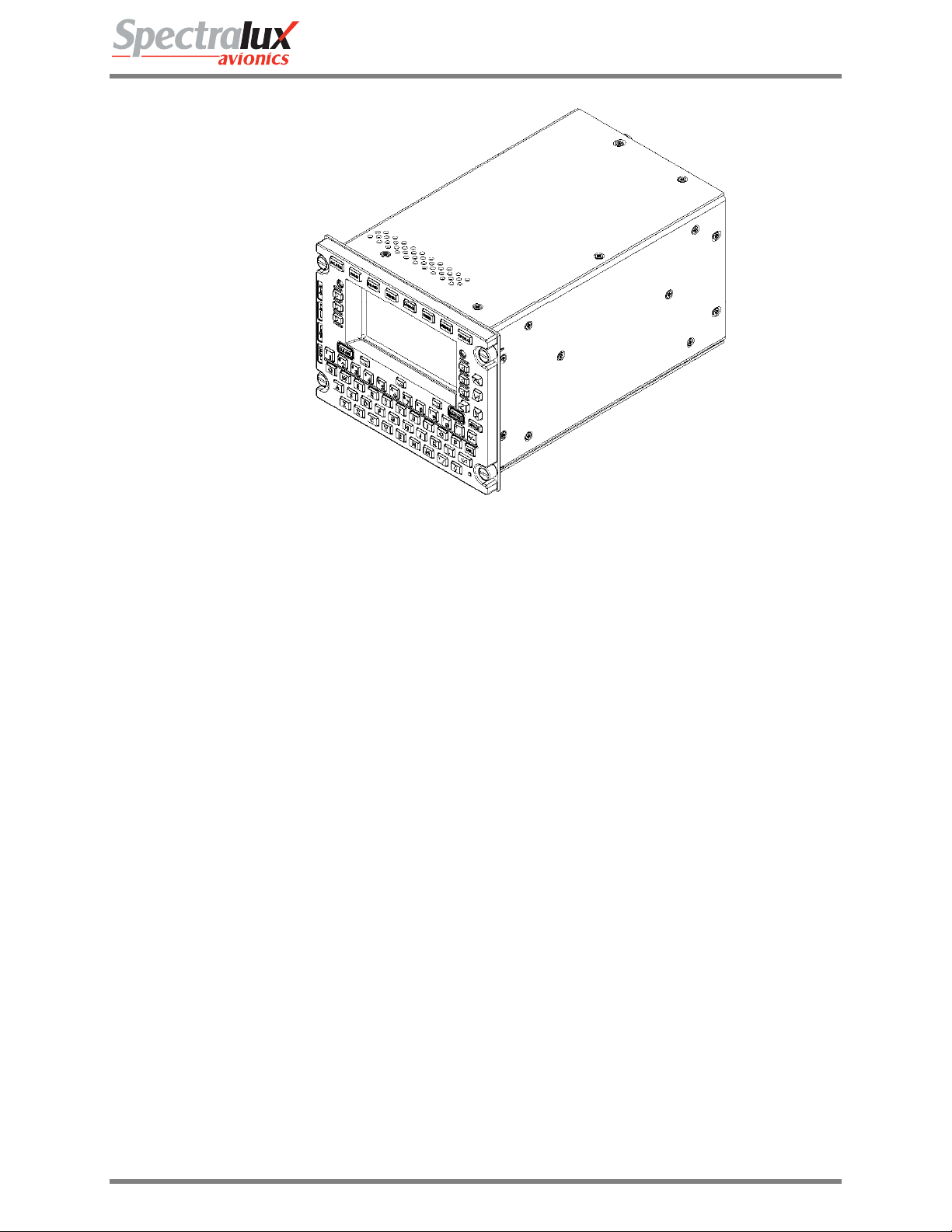
D. Figure 2-1 is a perspe ctive view of the Dlink+ w/CPDLC.
Document Number: INST-14114-1 Rev. - Page 4 of 25
INST-14114-1
Dlink+ w/CPDLC Installation Manual
Figure 2-2 - Perspective View of Dink+ (14114-1 shown)
E. General Specifications
• DZUS Mount 5.75” W x 4.5” H x 8.71” D (14.6 cm W x 11.4 cm H 22.1 cm D)
• Weight: 5.1 pounds (2.3 kg)
• Operating Temperature: -15°C to +55°C
• Short Time Operating Temperature: -40ºC to +70ºC with reduced power output at greater than
+55ºC
• Storage Temperature: -55°C to +85°C
• Environmental: DO-160E
F. Inputs
• 28 VDC (20.5 – 32.2 VDC), 25 watts standby, 160 watts transmitting
• RF (118 – 136.975 MHz)
• ARINC 429 Receivers 8
• Discretes 8
• 10 Base-T Ethernet 1
G. Outputs
• RF (118 – 136.975 MHz), 10 watts minimum
• ARINC 429 Transmitters 4
• Discretes 4
• 10 Base-T Ethernet 1
Document Number: INST-14114-1 Rev. - Page 5 of 25

INST-14114-1
Dlink+ w/CPDLC Installation Manual
3 Prepare for Installation
A. Installations must be performed per the requirements of FAA Advisory Circular (AC) 43.1 3-1B and
43.13-2B or later current revisions of these documents and any applicable documents referenced in
these ACs. The ACs describe installation processes including how to locate the Dlink+ w/CPDLC,
antenna requirements, wiring requirements, cable routing, mounting, circuit breaker information and
other required steps. The ACs also include inspection steps and best practice g uidance. Personnel
who perform installations must be qualified and must meet all applicable FAA requirements.
B. The Dlink+ w/CPDLC is designed to fit into a standard, 5.75” (14.6 cm) by 4.5” (11.43 cm) Dzus rail
mounting slot. There are two military circular connectors (one 11 pin connector and one 61 pin
connector) and one RF TNC connector mounted to the rear of the unit. These connectors prov ide all
input/output connections to the Dlink+ w/CPDLC. Tables 1 and 2 show the 11 pin and 61 pin
connections.
C. Connections:
• The Dlink+ w/CPDLC RF output is a TNC connector that is used to connect to the coaxial cable
running to an aircraft mounted VHF antenna. Use double-shielded coaxial cable RG400, or
equivalent.
The antenna will be vertically polarized and have a frequency range of 118.000-136.975 MHz.
The antenna installation should conform to the applicable RTCA DO-224, Signal-in-Space
Minimum Aviation System Performance Standards for Advanced VHF Digital Data
Communications Including Compatibility with Digital Voice Techniques. The VHF Communication
antenna must have a 50-ohm RF impedance with a maximum VSWR of 3:1. Maximum loss into
the antenna must be less than 5.5 dB. The maximum VSWR presented to the Dlink+ w/CPDLC
TNC connector must be 2:1 tested per RTCA DO-281.
• The 11-pin connector provides the power/ground, 5 Volt dimming bus, and personality module
interfaces. The 11-pin connector mates with an MS3476L18-11S connector with appropriate
strain relief. This mating connector uses #16 socket crimp contacts (M39029/5-116).
Non-emergency +28 VDC aircraft power is routed to the connector. This power is provided using
one or two 16 AWG wires. The wires are terminated with MS39029/5-116 contacts. The
contacts are inserted into the connector’s “A” and/or “L” positions. If both “A” and “L” conn ector
positions are used, they must be wired to the same power bus. A 7.5 amp circuit breaker must be
used for protection.
The 28 VDC return (ground) is provided using one or two 16 AWG wire(s). The wires are
terminated with MS39029/5-116 contacts. The contact is inserted into the connector’s “B” a nd/or
“K” position.
Chassis ground is connected using one 14 AWG wire into the connector’s “J” position.
The personality module may be tie wrapped to the power cable or mounted to a nearby bulkhead.
See installation instructions below.
• The 61-pin connector provides the unit’s signal interfaces. The 61-pin connector mates with an
MS3476L24-61S connector. This connector uses #20 socket crimp contacts (M39029/5-115).
Single wires for discretes and paired wires for ARINC 429 signals and for ethernet signals must
be used.
The unit was DO-160E qualified in two configurations.
One configuration used shielded single wires and shielded twisted pairs with the shields attached
to ground at both ends. Glenair backshells from the 40 series were used at the Dlink+ w/CP DLC
for short termination of shields to chassis.
Document Number: INST-14114-1 Rev. - Page 6 of 25
INST-14114-1
Dlink+ w/CPDLC Installation Manual
The other configuration used unshielded single wires and shielded twisted pairs. The shields
were grounded at both ends. At the Dlink+ w/CPDLC end, grounding was accomplish ed by
connecting the shields to ground pins of the 61-pin connector. The cable was stabilized by a
strain relief. To achieve passing RF emissions re sults with this configuration, it was necessary to
install Quell Corp. 18-11.9 and 24-61.35 FilterSeals in J1 and J2, respectively.
Other grounding and shielding schemes may be acceptable.
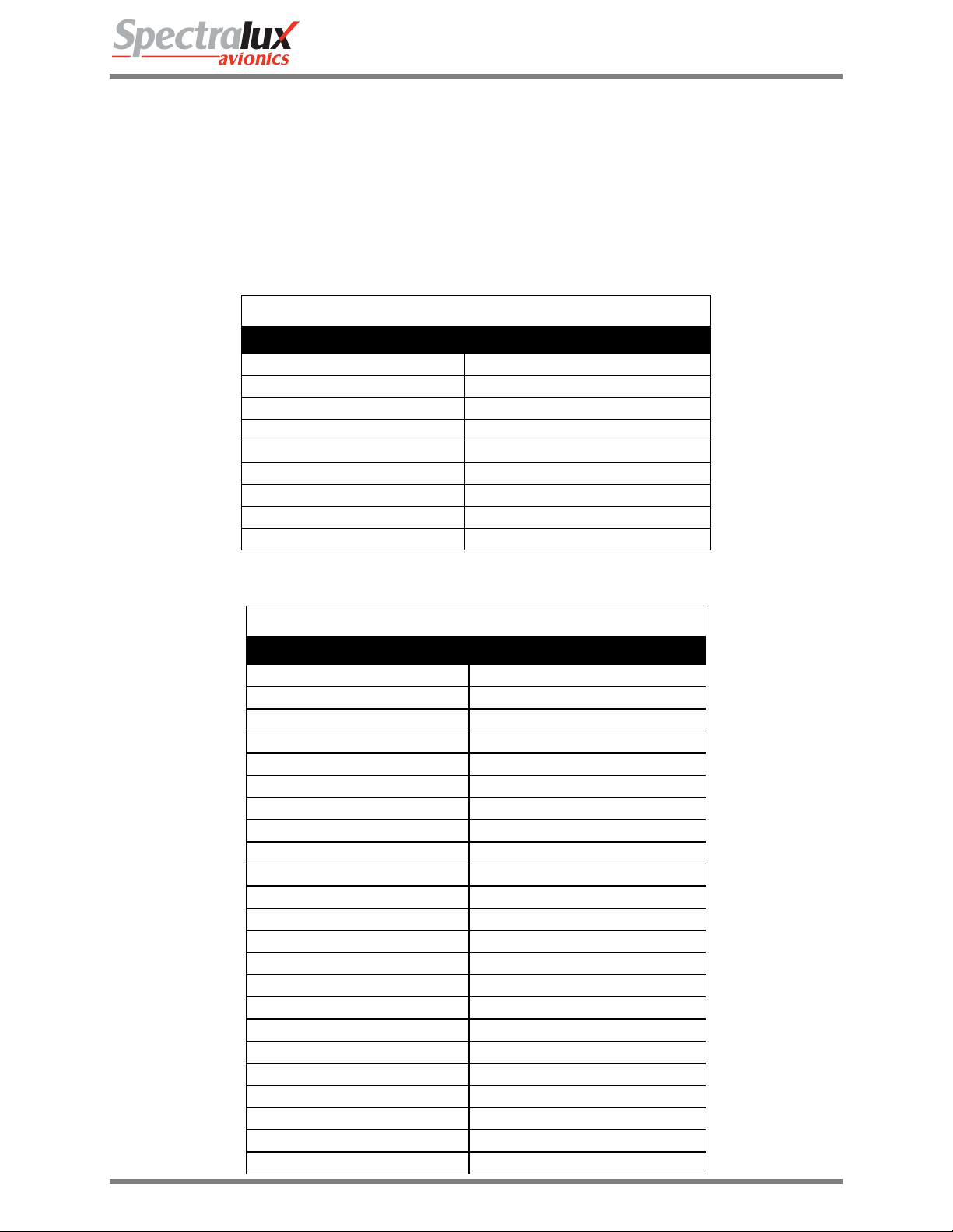
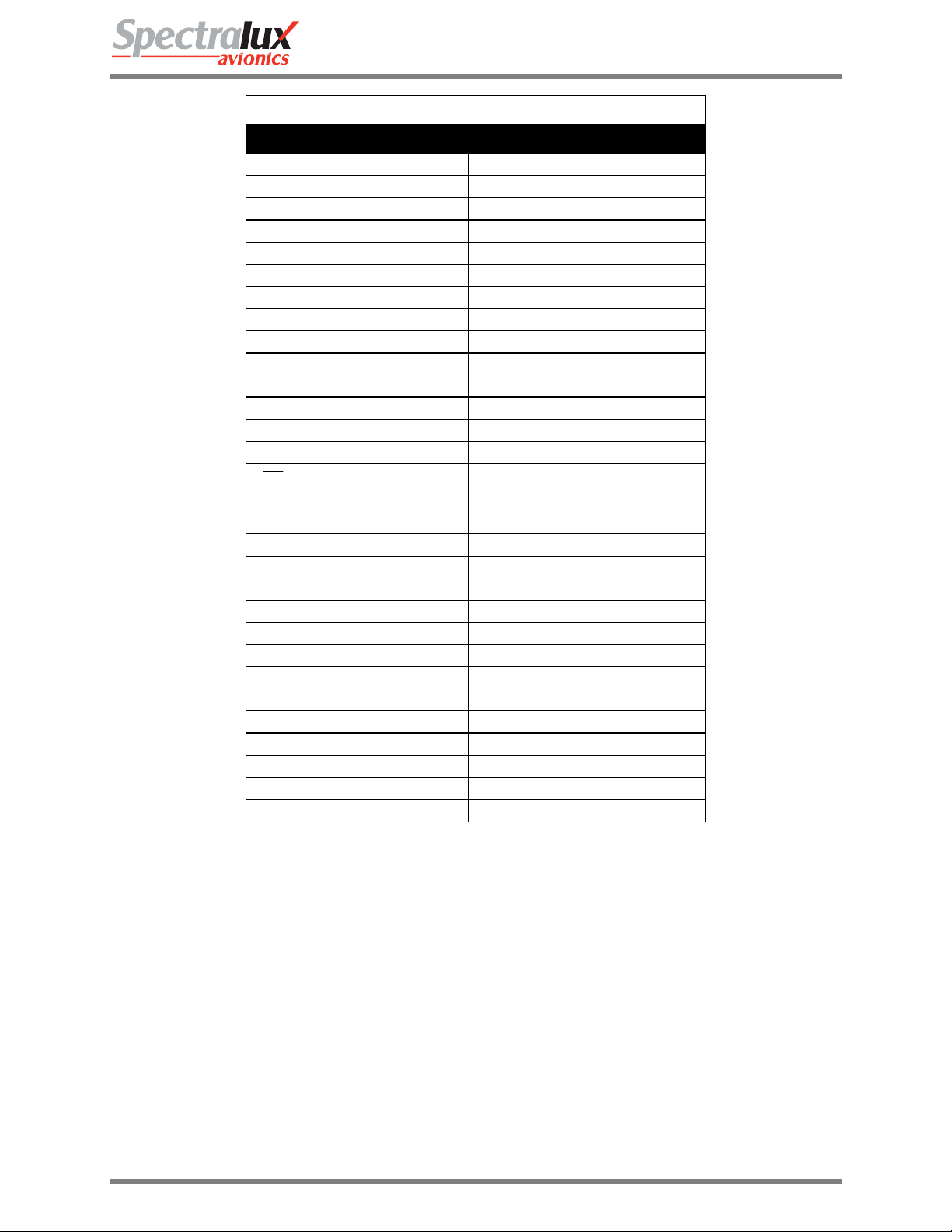
Table 1 - 11-Pin Connector Connections
11 Pin Military Circular Connections – Identifier - J1
Description Pin(s)
+28V DC POWER A, L
28V DC RETURN B, K
Personality Module CLOCK C
Personality Module DATA D
Personality Module +3.3V E
Personality Module GND F
Cockpit Dimming 5V G
Cockpit Dimming COMMON H
Chassis GROUND J
Table 2 - 61-Pin Connector Connections
61 Pin Military Connections - Identifier– J2
Description Pin(s)
Ground A, F, N, a, i, p, s, x, z, GG, KK
429 Transmit + Channel 1 AA
Ethernet Transmit + B
429 Receive + Channel 8 b
429 Transmit - Channel 1 BB
Ethernet Transmit - C
429 Receive - Channel 8 c
429 Receive + Channel 1 CC
Ethernet Receive + D
429 Receive + Channel 7 d
429 Receive - Channel 1 DD
Ethernet Receive - E
429 Receive - Channel 7 e
429 Receive + Channel 2 EE
Not Used f
429 Receive - Channel 2 FF
Output Discrete 1 G
Input Discrete 7 g
Output Discrete 2 H
Input Discrete 8 h
Not Used HH
Input Discrete 1 j
Output Discrete 3 J
Document Number: INST-14114-1 Rev. - Page 7 of 25
INST-14114-1
Dlink+ w/CPDLC Installation Manual
61 Pin Military Connections - Identifier– J2
Description Pin(s)
Not Used JJ
Input Discrete 2 k
Output Discrete 4 K
Input Discrete 5 L
Not used LL
Input Discrete 6 M
Not used m
Not used MM
Input Discrete 4 n
Not Used NN
429 Transmit + Channel 2 P
Not Used PP
Not Used q
429 Transmit - Channel 2 R
T/ R TRIGGER
(Factory test use only. Not
used on aircraft)
429 Receive + Channel 3 S
429 Receive - Channel 3 T
429 Transmit + Channel 3 t
429 Receive + Channel 4 U
429 Transmit - Channel 3 u
429 Receive - Channel 4 V
429 Transmit + Channel 4 v
429 Receive + Channel 5 W
429 Transmit - Channel 4 w
429 Receive - Channel 5 X
429 Receive + Channel 6 Y
Input Discrete 3 y
429 Receive - Channel 6 Z
r
D. Figure 3-1 provides the front, rear and side views.
E. Items required for installation will depend on the specific aircraft and situation. Installation items are
not furnished by Spectralux. The following items are required and should be selected and installed
per this document and the Advisory Circulars referenced above.
• Mounting hardware for Dlink+ w/CPDLC and personality module.
• Antenna with sealant.
• Cabling with proper connectors, routing and service loops.
F. Installation approval - The conditions and tests required for TSO approval of the Dlink+ w/CPDLC and
antenna are minimum performance standards. It is the responsibility of the installer to determine that
the aircraft installation standards for a specific type or class of aircraft are in compliance with all
applicable airworthiness standards. Installation in environments in excess of tho se liste d in Appendix
A is not permitted.
Document Number: INST-14114-1 Rev. - Page 8 of 25
 Loading...