

Spectralux 14114 Users Manual
Dlink+CPDLC Users Guide
Dlink+CPDLC Users Guide
SLC Doc Number UG-14114
Revision -
th
12335 134
Redmond, WA 98052
Tel: (425) 285-3000
Fax: (425) 285-4200
Email: info@spectralux.com
Court NE
USA
RESTRICTION ON USE, PUBLICATION, OR DISCLOSURE OF PROPRIETARY INFORMATION
This document contains information proprietary to Spectralux Corporation, or to a third party to which Spectralux Corporation may
have a legal obligation to protect such information from unauthorized disclosure, use, or duplication. Any disclosure, use, or
duplication of this document or of any of the information contained herein for other than the specific purpose for which it was
disclosed is expressly prohibited, except as Spectralux Corporation may otherwise agree in writing.
Preparer: Paul Newby 2011.12.31
Engineer: Paul Newby 2011.12.31
Program Manager: Robert W. Bernstein 2011.12.31
Quality Assurance David Cierebiej 2011.12.24
Document Number: UG-14114 Rev. - Page 1 of 201

Dlink+CPDLC Users Guide
CHANGE RECORD
Paragraph Description Of Change Approval/
Revision
Date
All Initial release Paul Newby
12/20/2011
-
SVN
21123
Document Number: UG-14114 Rev. - Page 2 of 201

Dlink+CPDLC Users Guide
Table of Contents
Dlink+CPDLC Users Guide ......................................................................................................................... 1
SLC Doc Number UG-14114 ....................................................................................................................... 1
Revision - ..................................................................................................................................................... 1
CHANGE RECORD ...................................................................................................................................... 2
1 Introduction .......................................................................................................................................... 7
1.1 Using the Dlink+ w/CPDLC ........................................................................................................... 8
1.1.1 Basic User Interface ................................................................................................................. 9
1.1.2 Keyboard ................................................................................................................................... 9
1.1.3 Advisories ................................................................................................................................ 11
2 Menu Page Tree ................................................................................................................................. 13
2.1 Menu Parameter Description ...................................................................................................... 14
3 Common Menus ................................................................................................................................. 15
3.1 Splash Screen ............................................................................................................................. 15
3.2 Main Menu ................................................................................................................................... 16
3.3 Main – Flight Information Menu ................................................................................................... 17
3.4 Main – Maintenance Menu .......................................................................................................... 18
3.4.1 Maintenance – Moni tor Menu Page 1 ..................................................................................... 19
3.4.2 Maintenance – Moni tor Menu Page 2 ..................................................................................... 21
3.4.3 Maintenance – System Control Messages Menu ................................................................... 22
3.4.4 Maintenance – Configuration Maintenance Menu .................................................................. 23
3.4.5 Maintenance - Set UTC Menu ................................................................................................. 24
3.4.6 Maintenance – Fail Status Menu............................................................................................. 25
3.5 Configuration Maintenance Menu ............................................................................................... 26
3.5.1 Configuration Maintenance – Password Menu ....................................................................... 26
3.5.2 Configuration Maintenance – User Edit Menu ........................................................................ 27
3.5.3 Configuration Maintenance – System Edit Menu .................................................................... 27
3.5.4 Configuration Maintenance – Software V ersions Menu .......................................................... 27
3.6 User Edit Menu ............................................................................................................................ 28
3.6.1 User Edit – Edit Configuration Menu Page 1 .......................................................................... 28
3.6.2 User Edit – Edit Configuration Menu Page 2 .......................................................................... 29
3.6.3 User Edit – Edit Configuration Menu Page 3 .......................................................................... 30
3.6.4 User Edit – Edit Configuration Menu Page 4 .......................................................................... 32
3.6.5 User Edit – Edit Configuration Menu Page 5 .......................................................................... 33
3.7 User Edit – Addresses Configuration Menu ................................................................................ 34
3.8 User Edit – User Defined Uplinks Menu ..................................................................................... 35
3.8.1 User Edit – Uplink Fo rmat Menu Page 1 ................................................................................ 35
3.8.2 User Edit – Uplink Fo rmat Menu Page 2 ................................................................................ 37
3.8.3 User Edit – Uplink Fo rmat Menu Page 3 ................................................................................ 39
Document Number: UG-14114 Rev. - Page 3 of 201

Dlink+CPDLC Users Guide
3.8.4 User Edit – Uplink Fo rmat Menu Page 4 ................................................................................ 41
3.9 User Event – User Defined Events Menu ................................................................................... 42
3.10 User Edit – User Defined Messages Menu ................................................................................. 44
3.10.1 User Edit – User Defined Message Edit Menu Page 1 ....................................................... 44
3.10.2 User Edit – User Defined Message Edit Menu Page 2 ....................................................... 45
3.10.3 Definition of Optional Data in User Defined Messages ....................................................... 50
3.11 User Edit – Software Versions Menu .......................................................................................... 54
3.11.1 User Edit – Software Versions Menu Page 1 ...................................................................... 54
3.11.2 User Edit – Software Versions Menu Page 2 ...................................................................... 55
3.12 System Edit Menu ....................................................................................................................... 56
3.12.1 System Edit – System Configuration Menu Page 1 ............................................................ 56
3.12.2 System Edit – System Configuration Menu Page 2 ............................................................ 57
3.12.3 System Edit – System Configuration Menu Page 3 ............................................................ 58
3.12.4 System Edit – System Configuration Menu Page 4 ............................................................ 59
3.12.5 System Edit – System Configuration Menu Page 5 ............................................................ 60
3.12.6 System Edit – System Configuration Menu Page 6 ............................................................ 61
3.12.7 System Edit – System Configuration Menu Page 7 ............................................................ 62
3.12.8 System Edit – System Configuration Menu Page 8 ............................................................ 63
3.12.9 System Edit – System Recall Information Menu ................................................................. 64
3.12.10 System Edit – Analog Input Discrete Configuration Menu .................................................. 65
3.12.11 System Edit – Digital Input Discrete Configuration Menu ................................................... 66
3.12.12 System Edit – Arinc 429 Input Configuration Menu ............................................................ 67
3.12.13 System Edit – Output Configuration Menu .......................................................................... 68
4 ACARS Menus .................................................................................................................................... 69
4.1 ACARS Index Menu .................................................................................................................... 69
4.1.1 ACARS Index – Service Messages Menu .............................................................................. 70
4.1.2 ACARS Index – ATS Requests Menu ..................................................................................... 71
4.1.3 ACARS Index – Message Log Menu ...................................................................................... 72
4.1.4 ACARS Index – System Control Messages Menu .................................................................. 74
4.1.5 ACARS Index – Station Table POA Stations Menu ................................................................ 75
4.1.6 ACARS Index – Station Table AOA Stations Menu ................................................................ 76
4.1.7 ACARS Index – Flight Information Menu ................................................................................ 77
4.2 ACARS Service Messages Menus.............................................................................................. 78
4.2.1 ACARS Service Messages – Weather Request Menu ........................................................... 78
4.2.2 ACARS Service Messages – Estimated Time of Arrival Report Menu ................................... 79
4.2.3 ACARS Service Messages – Diversion Report Menu ............................................................ 80
4.2.4 ACARS Service Messages – Position Report Menu Page 1 .................................................. 81
4.2.5 ACARS Service Messages – Position Report Menu Page 2 .................................................. 82
4.2.6 ACARS Service Messages – Estimated Time of Arrival Revision Menu ................................ 83
4.2.7 ACARS Service Messages – Engine Data Menu ................................................................... 84
Document Number: UG-14114 Rev. - Page 4 of 201

Dlink+CPDLC Users Guide
4.2.8 ACARS Service Messages – User Messages Menu .............................................................. 85
4.2.9 ACARS Service Messages – Aircrew Miscellaneous Message Menu .................................... 86
4.2.10 ACARS Service Messages – Service Message Setup Menu ............................................. 87
4.2.11 ACARS Service Messages – IATA Report Setup Menu Page 1 ........................................ 88
4.2.12 ACARS Service Messages – IATA Report Setup Menu Page 2 ........................................ 89
4.2.13 ACARS Service Messages – ICAO Report Setup Menu .................................................... 90
4.3 ATS Requests Menu ................................................................................................................... 91
4.3.1 ATS Request – ATIS Report Request Menu .......................................................................... 92
4.3.2 ATS Request – Clearance Request Menu .............................................................................. 93
4.3.3 ATS Request – Terminal Weather Information for Pilots Request Menu ............................... 98
4.3.4 ATS Request – ATS Free Text Message Menu ...................................................................... 99
4.4 System Control Messages Menu .............................................................................................. 100
4.4.1 System Control Messages – AVLC Ping Test Menu ............................................................ 101
4.4.2 System Control Messages – ACARS Ping Test Menu ......................................................... 102
5 ACARS Messages ............................................................................................................................ 103
5.1 ARINC 618 Formatted Messages ............................................................................................. 103
5.2 ARINC 622 Formatted Messages ............................................................................................. 104
6 ACARS Operation ............................................................................................................................ 105
6.1 Start up ...................................................................................................................................... 105
6.1.1 Entering the Flight Number ................................................................................................... 105
6.1.2 Entering Origin and Destination Stations .............................................................................. 105
6.2 Sending a Message .................................................................................................................. 105
6.2.1 Requirements for Sending a Message .................................................................................. 105
6.3 Reading Received Messages ................................................................................................... 105
7 CPDLC Operation............................................................................................................................. 106
7.1 CPDLC Menus ................................................................................................................... ....... 106
7.1.1 CPDLC – Index Menu ........................................................................................................... 106
7.1.2 CPDLC – Free Te xt Menu ..................................................................................................... 108
7.1.3 CPDLC – CM Logon Menu ................................................................................................... 109
7.1.4 CPDLC – Message Log Menu .............................................................................................. 112
7.1.5 CPDLC – Request Index Menu ............................................................................................. 115
7.1.6 CPDLC – Vertical Request Menu.......................................................................................... 117
7.1.7 CPDLC – Speed Request Menu ........................................................................................... 123
7.1.8 CPDLC – Route Mod Request Menu .................................................................................... 125
7.1.9 CPDLC – Request Weather Deviation Menu ........................................................................ 131
7.1.10 CPDLC – Lateral Offset Menu .......................................................................................... 133
7.1.11 CPDLC – When Can We Menu ......................................................................................... 137
7.1.12 CPDLC – Voice Request Menu ......................................................................................... 141
7.1.13 CPDLC – Report Index Menu ........................................................................................... 143
7.1.14 CPDLC – Heading/Altitude Report Menu .......................................................................... 145
Document Number: UG-14114 Rev. - Page 5 of 201

Dlink+CPDLC Users Guide
7.1.15 CPDLC – Monitoring Report Menu ................................................................................... 149
7.1.16 CPDLC – Position Report Menu ....................................................................................... 152
7.1.17 CPDLC – Speed Report Menu .......................................................................................... 155
7.1.18 CPDLC – Notification Menu .............................................................................................. 157
7.2 CPDLC Operational Scenario ................................................................................................... 159
7.2.1 CM Logon .............................................................................................................................. 159
7.2.2 CPDLC Start from the Ground .............................................................................................. 164
7.2.3 Vertical/Route Mod Message Exchange with ATC ............................................................... 165
7.2.4 Next Data Center Established ............................................................................................... 177
7.2.5 Change of Current Data Center ............................................................................................ 178
7.2.6 Contact Request.................................................................................................................... 179
7.3 Supported ATN CPDLC Messages ........................................................................................... 180
7.3.1 Uplink Messages Supported by Dlink+ w/CPDLC ................................................................ 180
7.3.2 Downlink Messages Supported by Dlink+ w/CPDLC ............................................................ 192
8 Events ............................................................................................................................................... 197
8.1 OOOI Events ............................................................................................................................. 197
8.1.1 Out Event .............................................................................................................................. 197
8.1.2 Off Event ............................................................................................................................... 197
8.1.3 On Event ............................................................................................................................... 197
8.1.4 In Event ................................................................................................................................. 197
8.1.5 Out Return In Event .............................................................................................................. 197
8.1.6 Reset Event ........................................................................................................................... 197
8.2 OOOI Initialize State ................................................................................................................. 197
9 Startup .............................................................................................................................................. 200
9.1 Visual Indicators ........................................................................................................................ 200
9.2 ACARS ...................................................................................................................................... 200
9.3 CPDLC ...................................................................................................................................... 200
10 Shutdown .......................................................................................................................................... 201
10.1 User-Initiated Reset .................................................................................................................. 201
Document Number: UG-14114 Rev. - Page 6 of 201
Dlink+CPDLC Users Guide
1 Introduction
The Dlink+ w/CPDLC unit provides aircraft and flight crews with the ability to send and receive Controller
Pilot Data Link Communications (CPDLC) and Aircraft Communications Addressing and Reporting
Systems (ACARS) messages over Very-High Frequency Digital Link (VDL) Mode A/2 networks. This
document is the user’s guide and is to be used for training purposes only.
Document Number: UG-14114 Rev. - Page 7 of 201
1.1 Using the Dlink+ w/CPDLC
The Dlink+ w/CPDLC emulates a 14-line ARINC 739 Multi-purpose Control and Display Unit (MCDU )
using a 9 line display to show the information in two parts called the A and B screens.
• The A screen puts the MCDU title line on line 1, MCDU lines 2 through 7 on display lines 2
through 7, and the MCDU scratch line (line 14) on line 8.
• The B screen puts the MCDU title line on line 1, MCDU lines 8 through 13 on display lines 2
through 7, and the MCDU scratch line (line 14) on line 8.
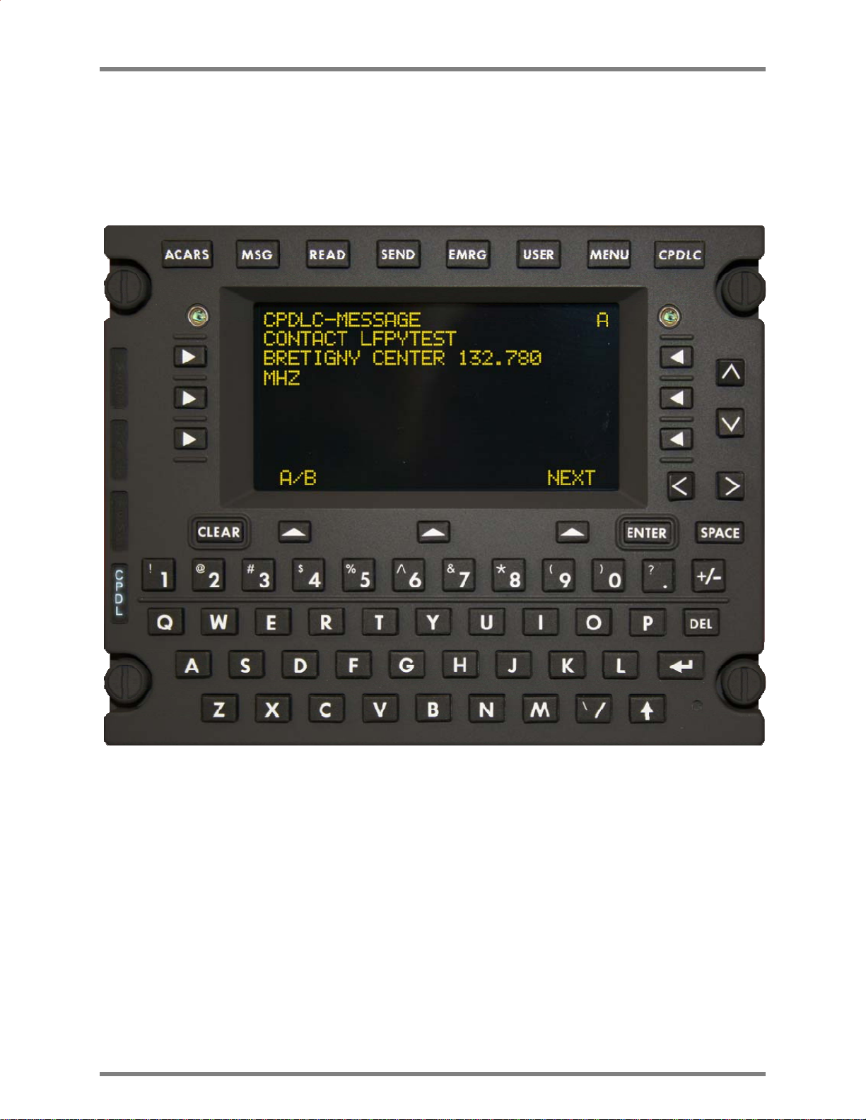
• When there is any text from MCDU line 8 through 13 on the B screen, the text above the lower
left Line Select Key (LSK) will read “A/B” and the rightmost character of display line 1 will show
the current screen (either A or B). Pressing the lower left LSK (“A/B”) will toggle between the two
screens.
Dlink+CPDLC Users Guide
T0 A
T1
T2
T3
T4
T5
T6
SCRATCH
A/B ADVISORY
T0 B
T7
T8
T9
T10
T11
T12
SCRATCH
A/B ADVISORY
Figure 1.1.1-1 Dlink+ w/CPDLC Text Line Identificaiton
Document Number: UG-14114 Rev. - Page 8 of 201
Dlink+CPDLC Users Guide
1.1.1 Basic User Interface
When first powered up or restarted, the Dlink+ w/CPDLC will appear as follows:
Note: The 1
st
line may have the airline name and unit version number.
1.1.2 Keyboard
Entering text from the keyboard will be shown on the “scratch pad” line located near the bottom of the
display. Entered text will start at column 1 and be added left to right. See Figure 1.1.1-1 Dlink+
w/CPDLC Text Line Identificaiton.
1.1.2.1 Alpha Numeric Keys
A standard QWERTY keyboard performs the expected functions. All alphabetic characters are always
upper case so they do not respond to the shift key.
1.1.2.2 Non Alpha Numeric Keys
1.1.2.2.1 User Function Keys
The user function keys are located at the top of the keyboard. Functionality is provided for each of
the keys. Function of each key is dependent on the state of the shift key.
Document Number: UG-14114 Rev. - Page 9 of 201

Dlink+CPDLC Users Guide
Functions associated with each non-shifted User Function Key:
• ACARS – Displays the ACARS Index Menu.
• MSG – Displays the ACARS messages log.
• READ – Displays the Monitor menu page.
• SEND – Displays the Aircrew Miscellaneous Message page.
• EMRG – Displays th e E7500 Menu.
• USER – Displays the Main System User Menu.
• MENU – Displays the Subsystem Menu.
• CPDLC – Displays the CPDLC Index Menu.
The following functions associated with each shifted User Function Key:
• ACARS – Displays the ACARS Index Menu.
• MSG – Displays the ACARS messages log.
• READ – Displays the Station Table Menu.
• SEND – Displays the ATS Free Text Menu.
• EMRG – Displays the E7500 Menu
• USER – Print the current ACARS message if displayed else print current menu.
• MENU – Displays the Subsystem Menu.
• CPDLC – Displays the CPDLC Index Menu.
Pressing the MENU user key selects the MCDU MAIN MENU where any additional devices using
the Dlink+ w/CPDLC as an MCDU can be selected. Normally this only displays” <DLINK+” for the
Dlink+ w/CPDLC internal display functionality.
1.1.2.2.2 Line Select Keys
There are 9 Line Select Keys (LSKs): 3 on the left and right sides of the display and 3 below the
display.
The function of the 3 lower LSKs are:
1) LEFT is the A/B select. This LSK will toggle between A and B screens. If there is no text
on the B screen the LSK is ignored and the text above the key is blank. If this LSK is held
for 2 seconds a “lamp test” is performed. The annunciator lamps will illuminate briefly then
go out and all of the pixels on the display will turn on while the key is held.
2) CENTER is below the Advisory field. Its function changes depending of the content of the
advisory field.
3) RIGHT is the NEXT/PREV page key. When the shift light is off this is NEXT and when the
shift light is on this is the PREV key. When a menu contains multiple pages, the right end
of line 1 (next to the A/B character) displays “n/m” where “n” is the current page and “m” is
the total number of pages. Pressing NEXT increments the current page and pressing PREV
decrements it. If the menu contains only 1 page pressing this LSK will cause the data on
the display to be refreshed.
The three left and right LSKs map to the 6 MCDU left and right LSKs. When the A screen is
displayed they map to MCDU LSKs 1 through 3 and when the B screen is displayed they map to
MCDU LSKs 4 through 6. The character on the display closest to the LSK determines the
function the LSK will perform.
1) “<” or “>” indicates another menu will be displayed.
2) “*” indicates a function will be called or a message will be sent.
3) “[“ and “]” indicates a selection field and each press of the LSK will select the next item in
the selection list.
Document Number: UG-14114 Rev. - Page 10 of 201

Dlink+CPDLC Users Guide
4) Any other characters normally indicate a variable field for data entry. Pressing the LSK
while the scratch line is blank will cause the current contents of the LSK variable to be
copied to the scratch line for editing. Pressing the LSK when there is data on the scratch
line causes the contents of the scratch line to be copied to the LSK field. The data is
verified before it is inserted and an error message is display for any problems.
5) Text can also be displayed on a line next to an LSK and the LSK will have no defined
function. In this case, pressing the LSK will result in a warning on the scratch line.
1.1.2.2.3 Arrow Keys
The function of the up (^), down (v), left (<), and right (>) arrow keys changes depending on the
circumstances:
1) Normal operation
• UP and DOWN move through multiple page menus ½ a screen at a time.
• LEFT is the equivalent of the Return key
• RIGHT is ignored.
2) Edit mode
• UP and DOWN have the same function as normal operation.
• LEFT and RIGHT move the cursor (an underscore) on the scratch line.
1.1.2.2.4 Clear Key
1) If a message is displayed on the scratch line it clears the message and restores the text
that was on the line.
2) If in edit mode it performs a backspace delete function.
3) If held for more than 1 second it clears the scratch line.
1.1.2.2.5 Enter Key
1) When data has been copied to the scratch line by pressing the associated LSK, pressing
ENTER stores the edited data to the original LSK field.
2) When entering a password the ENTER key enters and checks the password.
1.1.2.2.6 Del Key
The DEL key deletes the character under the cursor.
: (Shift is off, no data on the scratch line)
: (Shift is off, there is data on the scratch line)
1.1.2.2.7 Return Key
The Return key returns to the previous menu if there is one. If there is no previous menu it is
ignored.
1.1.2.2.8 +/- Key
This key displays a minus in the scratch pad on the first press and will toggle to + with a second
press. It does not change based on the shift key.
1.1.2.2.9 Shift Key
The shift key operates as a shift lock key. Pressing it toggles the shifted/not shifted lamp (lamp is
on when shifted). Do not hold down the shift key to produce a symbol from the numeric keys.
Simply press shift once to turn on the lamp then press the numeric key to get the desired symbol.
Press shift again to turn it off.
1.1.3 Advisories
The Advisories alert the pilot to messages or problems.
Document Number: UG-14114 Rev. - Page 11 of 201

Dlink+CPDLC Users Guide
1.1.3.1 Lamps
1.1.3.1.1 MSG Lamp
The MSG lamp illuminates when there is at least one unread message in the ACARS receive
buffer. The user can press the MSG user function key to display the ACARS receive buffer. Once
all the message(s) has been viewed the light will be extinguished.
1.1.3.1.2 Fail Lamp
The FAIL lamp is illuminated when a failure is detected in the Dlink+ w/CPDLC. The Dlink+
w/CPDLC may perform an automatic reset to clear the problem. If the problem cannot be cleared
the FAIL lamp will stay on and the Dlink+ w/CPDLC is considered failed and should be serviced.
The particular failure status can be viewed from the Maintenance Menu.
1.1.3.1.3 Temp Lamp
The TEMP lamp will illuminate when the temperature inside the Dlink+ w/CPDLC is too cold (less
than -41C, -41F) or too hot (greater than 90C, 194F) to function.
The Dlink+ w/CPDLC will stay in reset until the temperature returns to normal operation range.
1.1.3.1.4 CPDL Lamp
The CPDL lamp illuminates when there is at least one unread message in the CPDLC receive
buffer. The user can press the CPDLC user function key to display the CPDLC receive buffer.
Once all the message(s) has been viewed the light will be extinguished.
1.1.3.2 Discrete Outputs
These outputs are available through the 61-pin connector on the ba ck of the Dlink+ w/CPDLC.
1.1.3.2.1 ACARS Discrete Output
The ACARS Discrete output will follow the activity of the MSG Lamp, presenting an output ground
when the lamp is on and an open when the lamp is off on discrete output 3.
1.1.3.2.2 CPDLC Discrete Output
The CPDLC discrete output will follow the activity of the CPDL lamp, presenting an output ground
when the lamp is on and an output open when the lamp is off on discrete output 2.
1.1.3.2.3 CPDLC Chime Discrete Output
The CDPLC chime functionality is associated with the CPDL lamp and drives discrete output 1.
The output will present a ground when active and an open when not active. Characteristics of the
chime, pulse width and pulse spacing are part of the system configuration.
Document Number: UG-14114 Rev. - Page 12 of 201
Dlink+CPDLC Users Guide
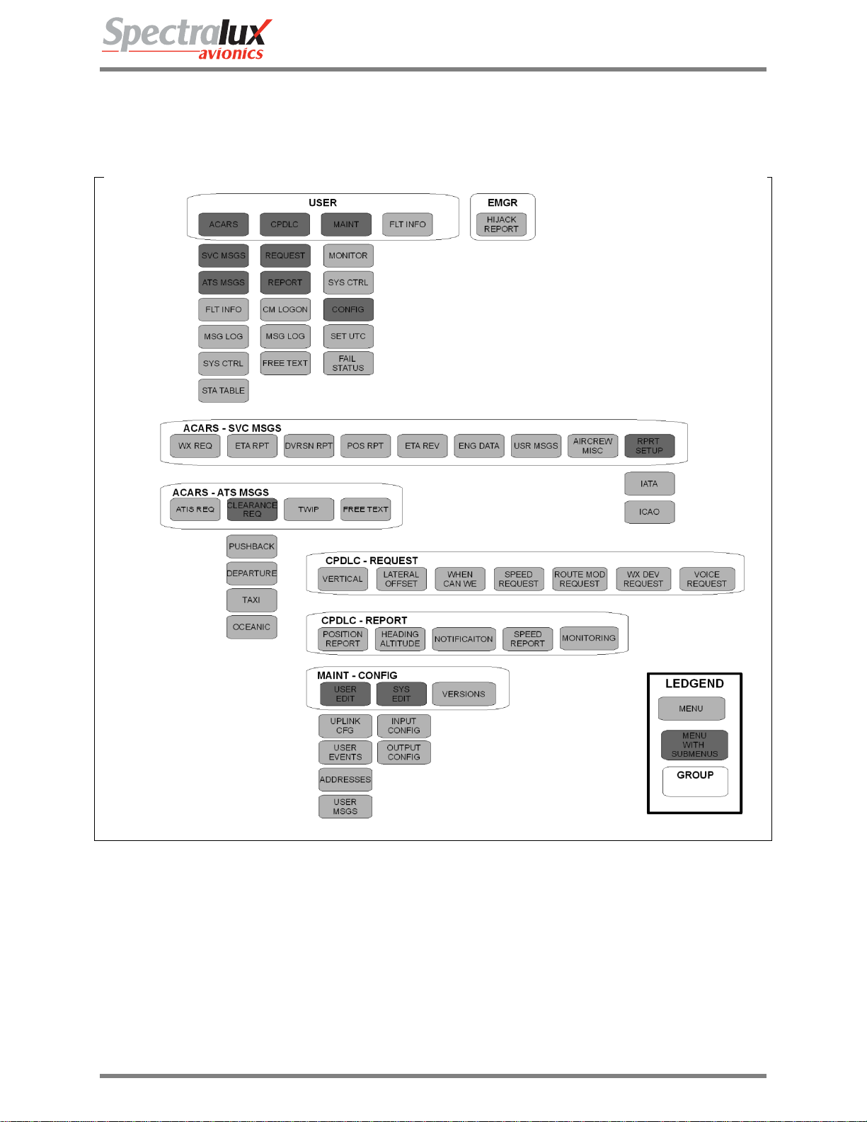
2 Menu Page Tree
Figure 1.1.3-1 Menu Tree
Document Number: UG-14114 Rev. - Page 13 of 201

Dlink+CPDLC Users Guide
2.1 Menu Parameter Description
Throughout this document the variable fields in menus will be described using notation listed in Table 1.
The fields in the menus are dynamic and will change as conditions or data change s.
Table 1 Variable Format Definition
Format
Format Definition Example
Identifier
A Alpha-numeric (AAAAA) – “DLINK”
N Numeric (N) – “1”
N.NN Numeric with decimal (N.NN) – “0.75”
SN Signed Numeric (SN) – “-9”
SN.N Signed Numeric with
(SN.N) – “9.9”
decimal
B BCD (BBB) – “51E”
Z Numeric with leading zeros (ZZZ) – “042”
P Password (PPPPPP) – USER PASSWORD.
Will be displayed as “******”
Document Number: UG-14114 Rev. - Page 14 of 201
Dlink+CPDLC Users Guide
3 Common Menus
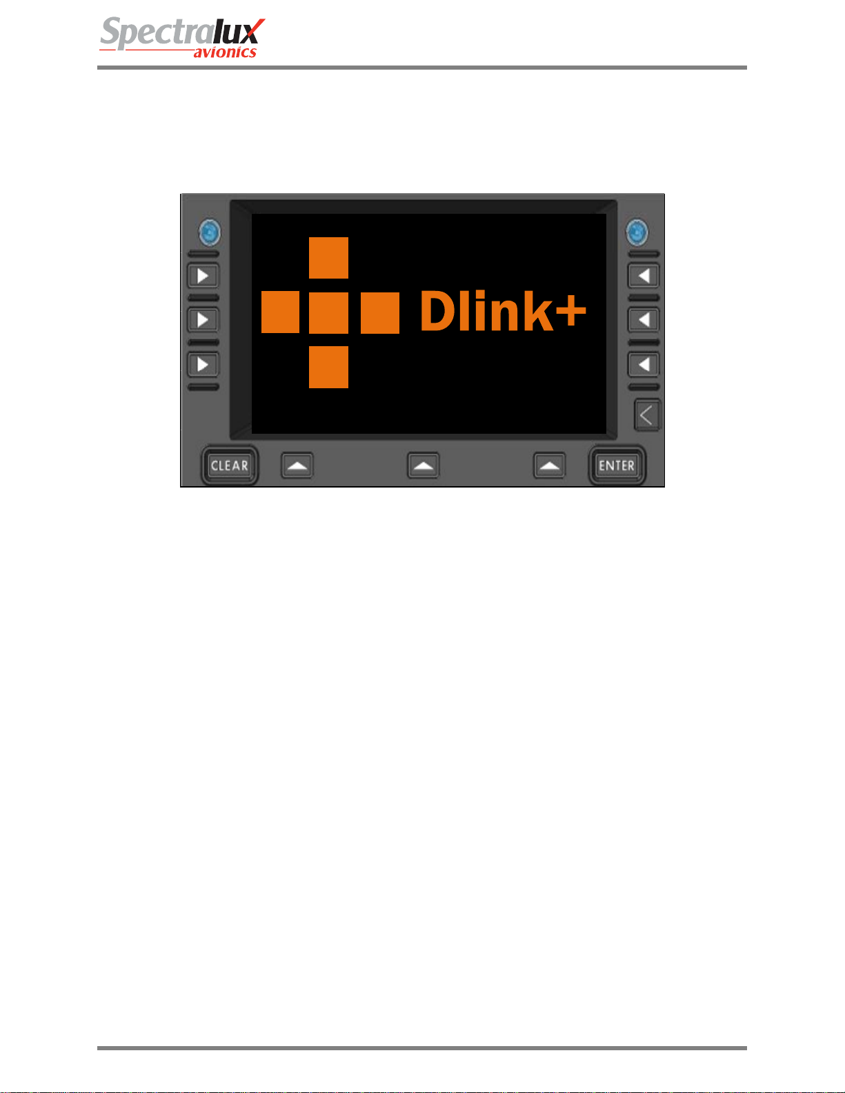
3.1 Splash Screen
The Splash screen is presented when the Dlink+ w/CPDLC is first powered on or after a restart. This
screen should stay present for approximately 5 seconds before transitioning to the main menu.
Figure 1.1.3-1 Splash Screen
Document Number: UG-14114 Rev. - Page 15 of 201
Dlink+CPDLC Users Guide
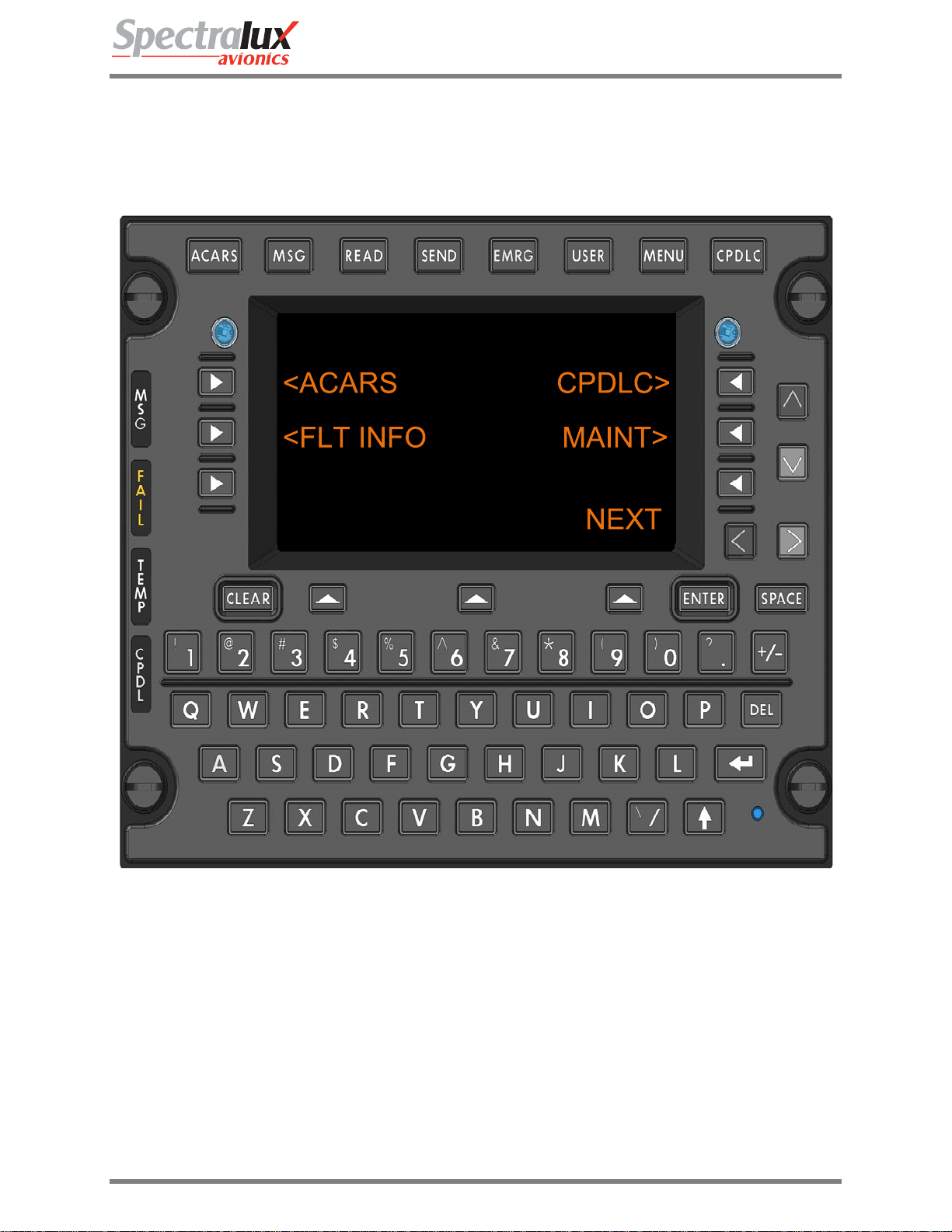
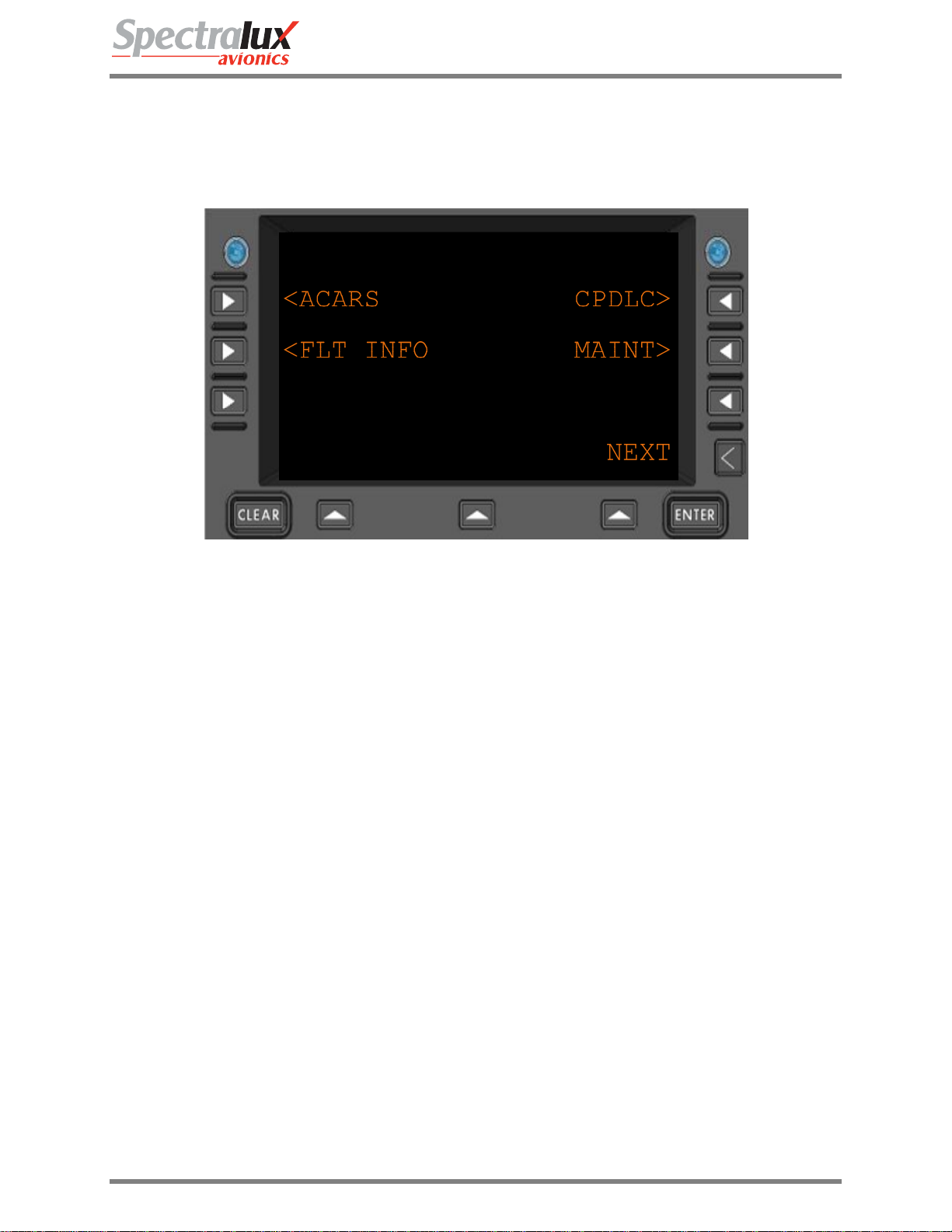
3.2 Main Menu
The Main menu is the starting or home menu, and can be accessed directly by pressing the USER key.
Note: The 1
st
line may have the airline name and unit version number.
Figure 1.1.3-1 Main Menu
<ACARS
<FLT INFO
CPDLC>
MAINT>
RETURN
Navigate to the ACARS Menu
Navigate to the Flight Information Menu
Navigate to the CPDLC Menu
Navigate to the Maintenance Menu
Return to previous page
Document Number: UG-14114 Rev. - Page 16 of 201
Dlink+CPDLC Users Guide
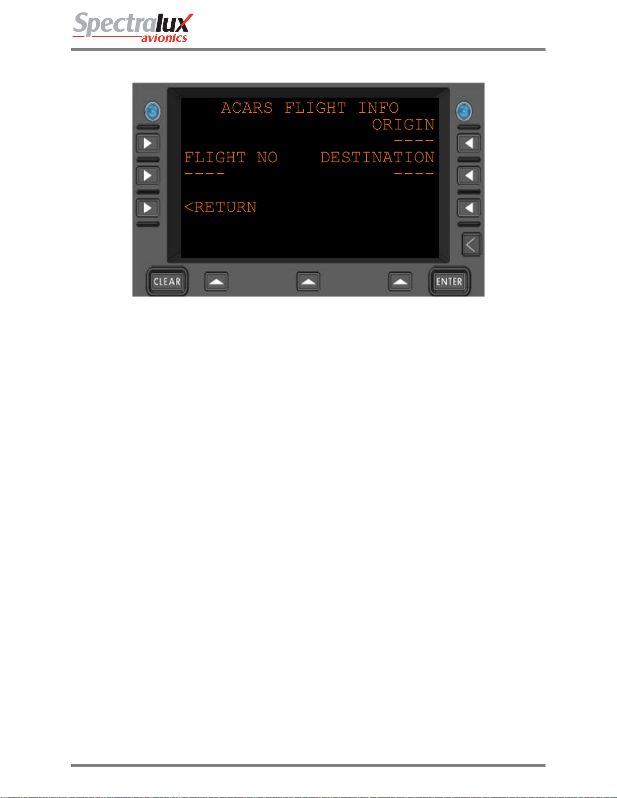
3.3 Main – Flight Information Menu
FLIGHT NO
ORIGIN
DESTINATION
RETURN
Figure 1.1.3-1 Flight Information Menu
Flight number.
Format: 1-4 alpha-numeric characters. (AAAA)
Flight departure (origin) station.
Format: 3-4 alpha characters (AAAA)
Flight destination station
Format: 3-4 alpha characters (AAAA)
Return to previous page
Document Number: UG-14114 Rev. - Page 17 of 201
Dlink+CPDLC Users Guide
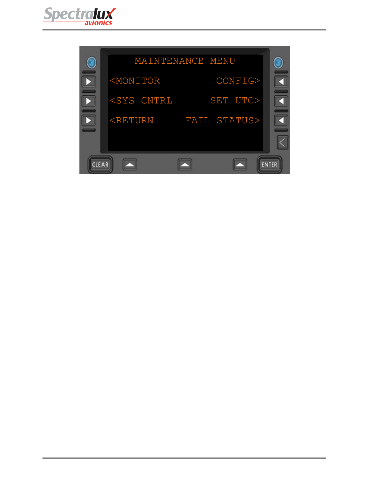
3.4 Main – Maintenance Menu
Figure 1.1.3-1 Maintenance Menu
<MONITOR
<SYS CNTRL
CONFIG>
SET UTC>
FAIL STATUS>
<RETURN
Navigate to the MONITOR menu
Navigate to the SYS CNTRL menu
Navigate to the CONFIG menu
Navigate to the SET UTC menu
Navigate to the FAIL STATUS menu
Return to previous page
Document Number: UG-14114 Rev. - Page 18 of 201
Dlink+CPDLC Users Guide
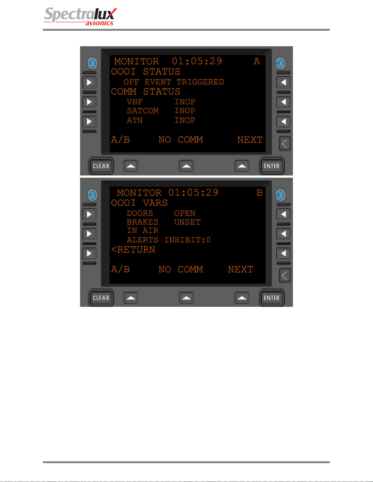
3.4.1 Maintenance – Monitor Menu Page 1
Figure 3.4.1-1 Monitor Menu 1
OOOI
Status
COMM
STATUS
Document Number: UG-14114 Rev. - Page 19 of 201
Reports the current state of the OOOIs
"INITIALIZING STATE...", "WAITING FOR OUT",
"OUT EVENT TRIGGERED", "RETURN EVENT TRIGGERED",
"OFF EVENT TRIGGERED", "ON EVENT TRIGGERED",
"IN EVENT TRIGGERED"
Reports the current communication status
• VHF
“INOP”,
“M2 AVAIL”,
“MA AVAIL”,
“NO COMM”
• SATCOM
“AVAILABLE”,
“NO COMM”,
“INOP”
• ATN
“AVAILABLE”,

Dlink+CPDLC Users Guide
“INOP”,
“UNAVAIL”
OOOI VARS
Reports the current state of OOOI variables.
• DOORS
“DOORS CLOSED”,
“DOORS OPEN”
• BRAKES
“BRAKES UNSET”,
“BRAKES SET”
• AIR GROUND
“ON GROUND”,
“IN AIR”
• ALERTS INHIBIT
“0”,
“1”
<RETURN
Return to previous page
Document Number: UG-14114 Rev. - Page 20 of 201
Dlink+CPDLC Users Guide
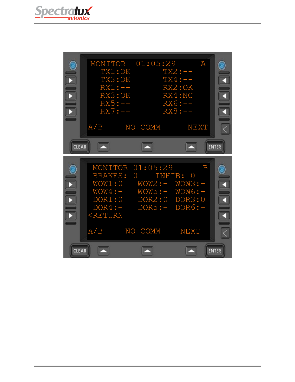
3.4.2 Maintenance – Monitor Menu Page 2
TX(1-4) or
RX(1-8)
Figure 3.4.2-1 Monitor Menu 2
The ARINC 429 channel being monitored.
Statuses:
“OK” – channel has valid activity
“NC” – channel has no valid activity
“- -“ – channel is not part of the system configuration.
Discrete
Inputs
WOW(1-6) – Weight On Wheels input used for Air / Ground logic.
DOR(1-6) – Doors used for all doors open / closed logic
BRAKES – input from the brakes used in brakes set logic.
INHIB – the “flaps up” signal used to inhibit annunciators.
<RETURN
Return to previous page
Document Number: UG-14114 Rev. - Page 21 of 201
Dlink+CPDLC Users Guide
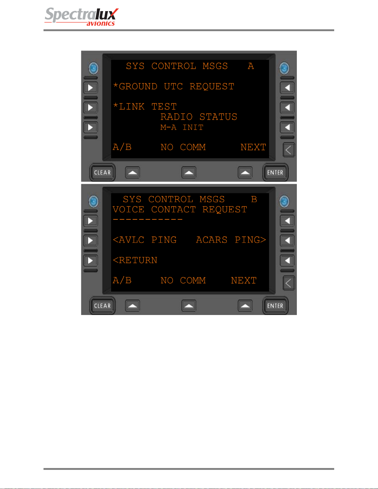
3.4.3 Maintenance – System Control Messages Menu
Figure 3.4.3-1 Sys Control Menu
*GROUND UTC
REQUEST
*LINK TEST
RADIO STATUS
VOICE
CONTACT
REQUEST
<AVLC PING
ACARS PING>
<RETURN
Send a Universal Coordinated Time request to the ground.
Flight number must be filled in prior to request being sent.
Send a link test (Label Q0) to the ground.
Flight number must be filled in prior to request being sent.
The current radio operation. What is currently being sent or received
or follow-on operation due to previous uplink or downlink.
Will send a Label 54 messages requesting voice contact at the entered
frequency.
Format: 10 digits (AAAAAAAAAA)
Navigate to the AVLC PING menu
Navigate to the ACARS PING menu
Return to previous page
Document Number: UG-14114 Rev. - Page 22 of 201
Dlink+CPDLC Users Guide
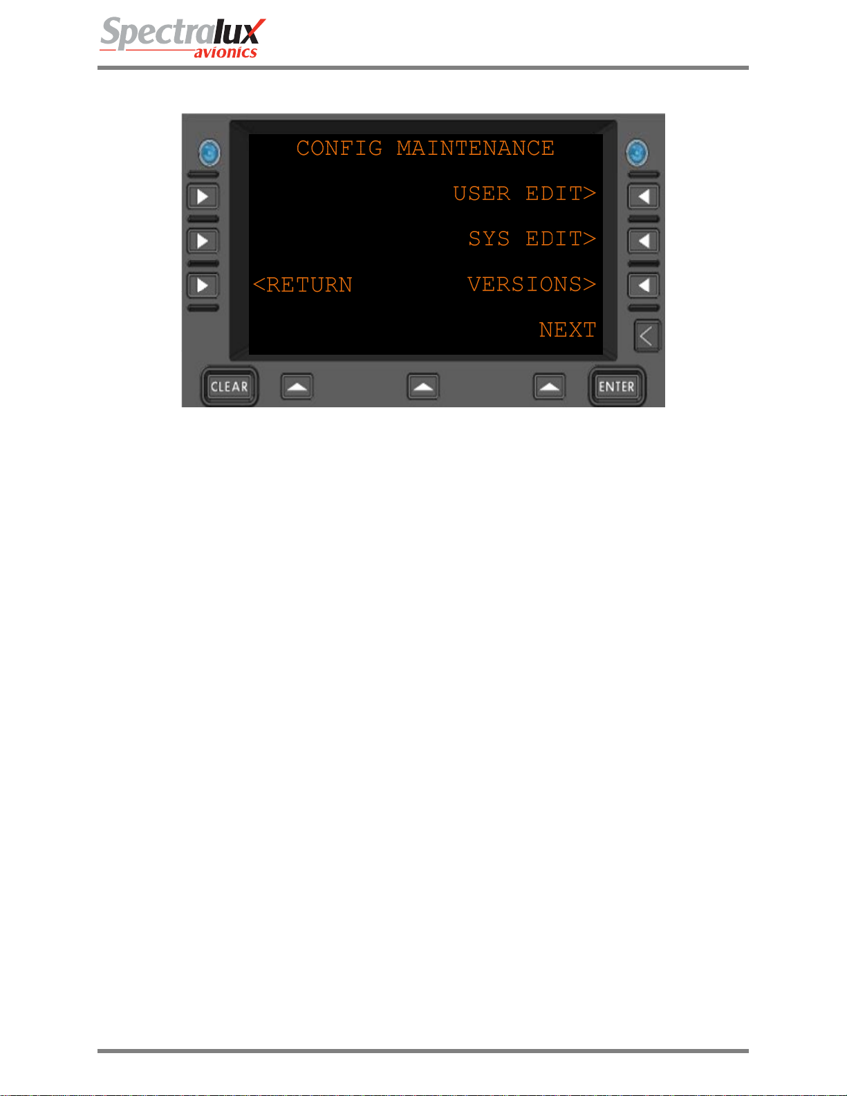
3.4.4 Maintenance – Configuration Maintenance Menu
Figure 3.4.4-1 Configuration Menu
USER EDIT>
SYS EDIT>
VERSIONS>
<RETURN
Navigate to the USER EDIT menu
Navigate to the SYS EDIT menu
Navigate to the VERSIONS menu
Return to previous page
Document Number: UG-14114 Rev. - Page 23 of 201

Dlink+CPDLC Users Guide
3.4.5 Maintenance - Set UTC Menu
Figure 3.4.5-1 Set UTC Menu
Date
Time
+1
SECOND*
-1
SECOND*
<RETURN
The current date
Format: MM-DD-YY
The current time
Format: HH-MM-SS
Advance the current time by one second
Retard the current time by one second.
Return to previous page
Document Number: UG-14114 Rev. - Page 24 of 201
Dlink+CPDLC Users Guide
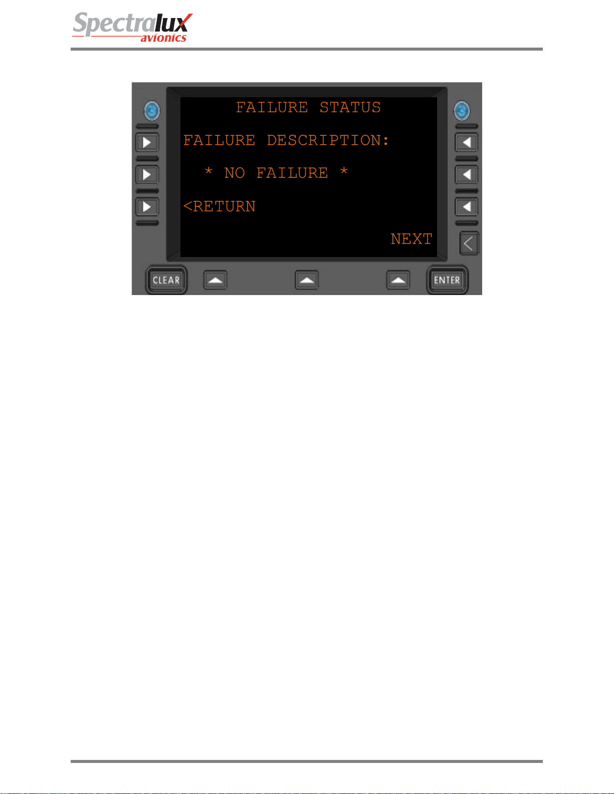
3.4.6 Maintenance – Fail Status Menu
Figure 3.4.6-1 Fail Status Menu
FAILURE
DESCRIPTION:
<RETURN
The Current failure, if present. The FAIL annunciator will also be lit if a
failure is present.
Format: 22 Characters
Return to previous page
Document Number: UG-14114 Rev. - Page 25 of 201
Dlink+CPDLC Users Guide
3.5 Configuration Maintenance Menu
The configuration information, accessed through the Configuration Maintenance Menu, is password
protected. There are two separate areas, User and System, each requiring a unique password. The
system password and access to its data area are only available to authorized Spectralux maintenance
personnel.
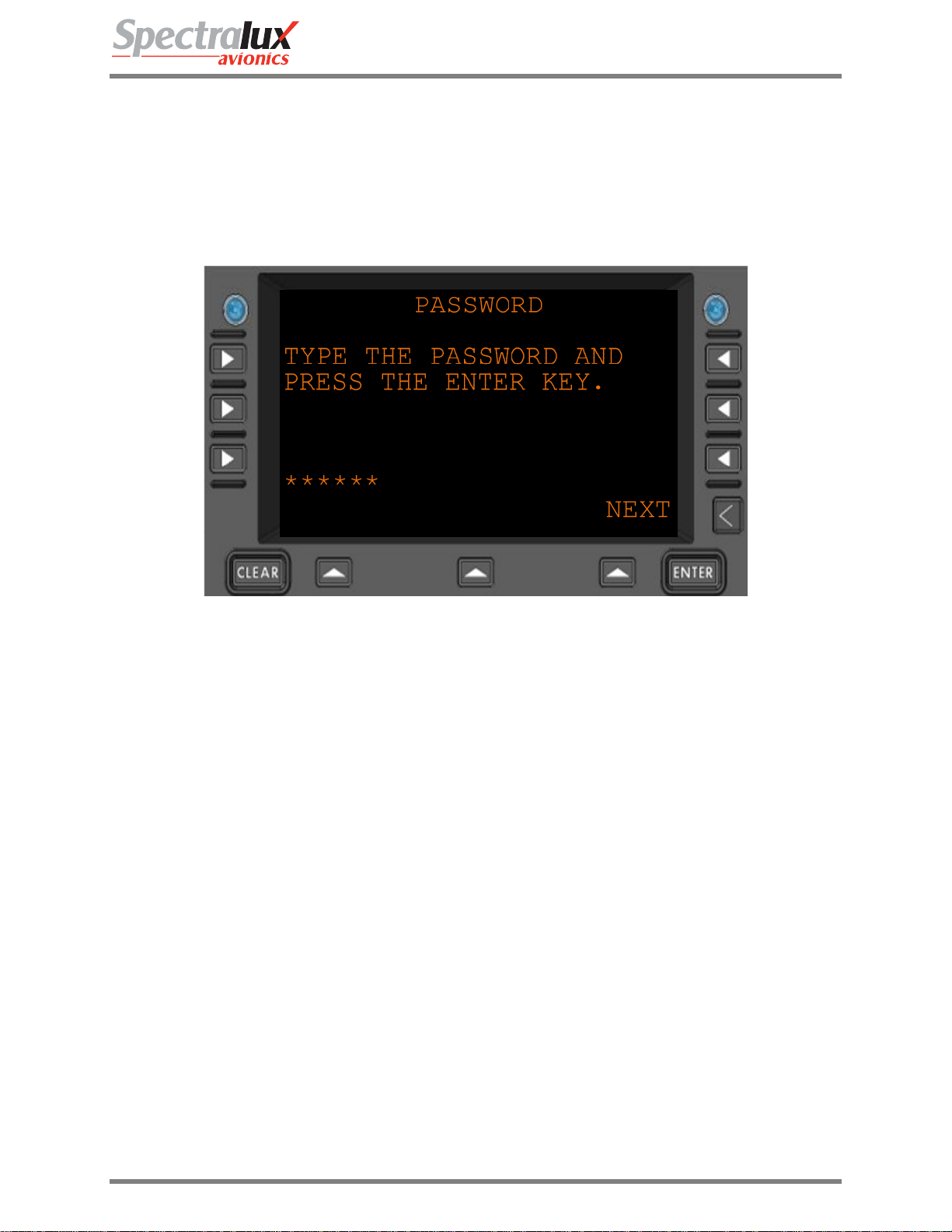
3.5.1 Configuration Maintenance – Password Menu
Figure 3.5.1-1 Password Menu
******
Password entered by the user
ENTER
Pressing the ENTER key will accept the password
Document Number: UG-14114 Rev. - Page 26 of 201

Dlink+CPDLC Users Guide
3.5.2 Configuration Maintenance – User Edit Menu
See User Edit Menu
3.5.3 Configuration Maintenance – System Edit Menu
See System Edit Menu
3.5.4 Configuration Maintenance – Software Versions Menu
See User Edit Menu – Software Versions
Document Number: UG-14114 Rev. - Page 27 of 201
Dlink+CPDLC Users Guide
3.6 User Edit Menu
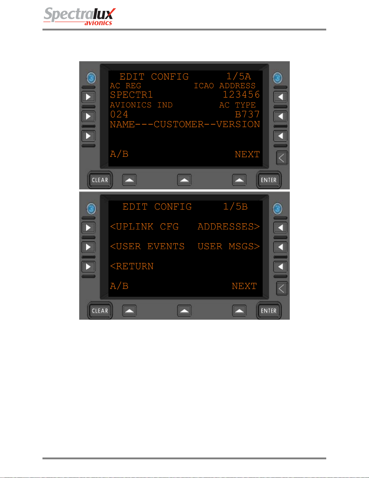
3.6.1 User Edit – Edit Configuration Menu Page 1
AC REG
ICAO ADDRESS
AVIONICS IND
AC TYPE
CUSTOMER NAME
CUSTOMER VERSION
Figure 3.6.1-1 Edit Configuration Menu
Aircraft registration
Format: (AAAAAAA)
ICAO Address
Format: 6 hex-digits
Avionic indicator, the page width of printed messages.
Format: (ZZZ)
Aircraft type
Format: (AAAA)
Customer defined text
Format: 14 characters (AAAAAAAAAAAAAA)
Customer defined text
Document Number: UG-14114 Rev. - Page 28 of 201
Dlink+CPDLC Users Guide
Format: (AAAAA)
<UPLINK CFG
<USER EVENTS
ADDRESSES>
USER MSGS>
<RETURN
Navigate to the UPLINK CFG menu
Navigate to the USER EVENTS menu
Navigate to the ADDRESSES menu
Navigate to the USER MSGS menu
Return to previous page
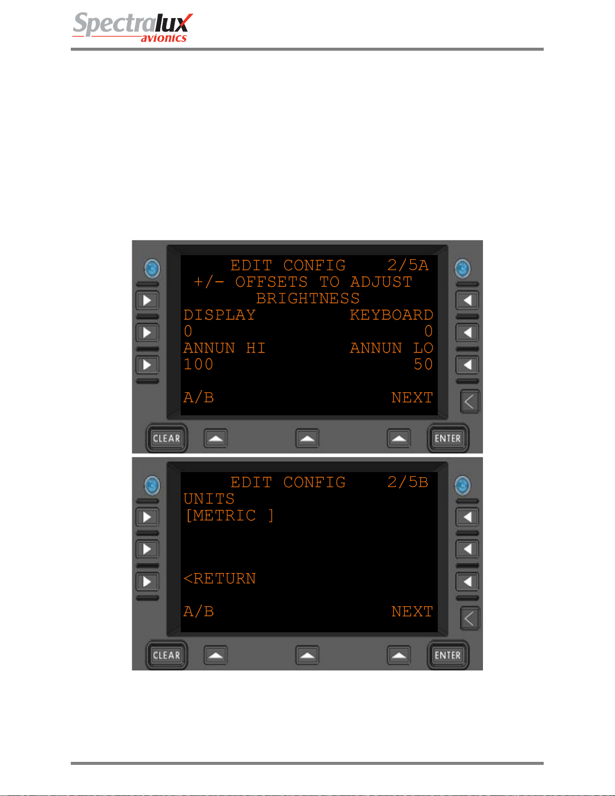
3.6.2 User Edit – Edit Configuration Menu Page 2
Figure 3.6.2-1 Edit Configuration Menu 2
DISPLAY
Display brightness offset adjustment
Format: 4 digits, signed +/- 2000
Document Number: UG-14114 Rev. - Page 29 of 201

Dlink+CPDLC Users Guide
KEYBOARD
Keyboard brightness offset adjustment
Format: 4 digits, signed +/- 2000
ANNUN HI
Annunciator HI brightness offset adjustment
Format:3 digits. 0-100 percent
ANNUN LO
Annunciator LO brightness offset adjustment
Format:3 digits 0-100 percent
UNITS
Which format are units displayed in.
Format: “ENGLISH”, “METRIC”
<RETURN
Return to the previous page.
3.6.3 User Edit – Edit Configuration Menu Page 3
Figure 3.6.3-1 Edit Configuration Menu 3
POA
A listing of the POA (Plain Old ACARS) service providers, in order of
preference.
Up to 3 can be listed.
Format: 4 characters (Service Provider [2 chars], “-“, Network type ( A or B )
Document Number: UG-14114 Rev. - Page 30 of 201
 Loading...