

Page 1

Spectra T120 Library
User Guide
P.N. 90950000 Revision C
Page 2

Notices
Spectra Logic Contact Information
United States Headquarters European Office
Mailing Address Spectra Logic Corporation
1700 N 55th Street
Boulder CO 80301
USA
Phone
Fax
(800) 833-1132 or (303) 449-6400
(303) 939-8844
Web Site http://www.SpectraLogic.com
Notices
Mailing Address Spectra Logic Europe Limited
Hampden House
Monument Business Park
Warpsgrove Lane
Chalgrove Oxon
UK-OX44 7RW
Phone
Fax
+44 (0) 870 112 2150
+44 (0) 870 112 2175
Except as expressly stated herein, Spectra Logic Corporation makes available the Spectra T120 library and
associated documentation on an “as is” basis, without warranty of any kind, either expressed or implied,
including but not limited to the implied warranties of merchantability or fitness for a particular purpose. In
no event shall Spectra Logic be liable for any loss of profits, loss of business, loss of use or data, interruption
of business, or for indirect, special, incidental or consequential damages of any kind, even if Spectra Logic
has been advised of the possibility of such damages arising from any defect or error.
Information furnished in this manual is believed to be accurate and reliable. However, no responsibility
is assumed by Spectra Logic for its use. Due to continuing research and development, Spectra Logic may
revise this publication from time to time without notice, and reserves the right to change any product
specification at any time without notice.
Some products or services mentioned in this manual are provided by companies other than Spectra
Logic. Inquiries about one or more of these products or services should be sent directly to the company
in question.
RXT, BlueScale, Spectra, SpectraGuard, TeraPack, and the Spectra Logic logo are registered trademarks of Spectra Logic
Corporation. All rights reserved worldwide. All other trademarks and registered trademarks are the property of their
respective owners.
Spectra T120 Library User Guide
Copyright © 2007 Spectra Logic Corporation. All rights reserved.
2
Page 3

Notices
License
You have acquired a Spectra T120 library that includes software owned or licensed by Spectra Logic from one
or more software licensors (“Software Suppliers”). Such software products, as well as associated media,
printed materials and online or electronic documentation (“Software”) are protected by copyright laws and
international copyright treaties, as well as other intellectual property laws and treaties.
If you do not agree to this end user license agreement (EULA), do not use the Spectra T120 library;
instead, promptly contact Spectra Logic for instructions on return of the Spectra T120 library for a
refund. Any use of the Software, including but not limited to use on the Spectra T120 library, will
constitute your agreement to this EULA (or ratification of any previous consent).
Grant of License. The Software is licensed on a non-exclusive basis, not sold. This EULA grants you the
following rights to the Software:
• You may use the Software only on the Spectra T120 library.
• Not Fault Tolerant. The Software is not fault tolerant. Spectra Logic has independently determined how
to use the Software in the Spectra T120 library, and suppliers have relied upon Spectra Logic to
conduct sufficient testing to determine that the Software is suitable for such use.
• No Warranties For the SOFTWARE. The Software is provided “AS IS” and with all faults. The entire risk
as to satisfactory quality, performance, accuracy, and effort (including lack of negligence) is with you.
Also, there is no warranty against interference with your enjoyment of the Software or against
infringement. If you have received any warranties regarding the Software, those warranties do not
originate from, and are not binding on Software Suppliers.
• Note on Java Support. The Software may contain support for programs written in Java. Java technology
is not fault tolerant and is not designed, manufactured, or intended for use of resale as online control
equipment in hazardous environments requiring fail-safe performance, such as in the operation of
nuclear facilities, aircraft navigation or communications systems, air traffic control, direct life support
machines, or weapons systems, in which the failure of Java technology could lead directly to death,
personal injury, or severe physical or environmental damage.
• No Liability for Certain Damages. Except as prohibited by law, Software Suppliers shall have no liability
for any indirect, special, consequential or incidental damages arising from or in connection with the
use or performance of the Software. This limitation shall apply even if any remedy fails of its essential
purpose. In no event shall Software Suppliers, individually, be liable for any amount in excess of U.S.
two hundred fifty dollars (U.S. $250.00).
• Limitations on Reverse Engineering, Decompilation, and Disassembly. You may not reverse engineer,
decompile, or disassemble the Software, except and only to the extent that such activity is expressly
permitted by applicable law notwithstanding this limitation.
• Software Transfer Allowed with Restrictions. You may permanently transfer rights under this EULA only
as part of a permanent sale or transfer of the Spectra T120 library, and only if the recipient agrees to
this EULA. If the Software is an upgrade, any transfer must also include all prior versions of the
Software.
• Export Restrictions. Export of the Software from the United States is regulated by the Export
Administration Regulations (EAR, 15 CFR 730-744) of the U.S. Commerce Department, Bureau of
Export Administration. You agree to comply with the EAR in the export or re-export of the Software:
(i) to any country to which the U.S. has embargoed or restricted the export of goods or services,
which as May 1999 include, but are not necessarily limited to Cuba, Iran, Iraq, Libya, North Korea,
Sudan, Syria, and the Federal Republic of Yugoslavia (including Serbia, but not Montenegro), or to any
national or any such country, wherever located, who intends to transit or transport the Software back
to such country; (ii) to any person or entity who you know or have reason to know will utilize the
Software or portion thereof in the design, development or production of nuclear, chemical, or
biological weapons; or (iii) to any person or entity who has been prohibited from participating in U.S.
export transactions by any federal agency of the U.S. government. You warrant and represent that
neither the BXA nor any other U.S. federal agency has suspended, revoked or denied your export
privileges. For additional information see http://www.microsoft.com/exporting/.
3
Page 4

Warnings and Cautions
Media
Caution: Use only the data cartridges approved for use in the particular
drives installed in your library. Improper data cartridges will
result in damage to the drives, library, and cartridges.
Vorsicht: Benutzen Sie nur die Datencartridges, die für die Verwendung
in den Laufwerken zugelassen sind, die in Ihrer Library
installiert sind. Nicht zugelassene Datencartridges können zur
Beschädigung der Laufwerke, der Library und der
Datencartridges führen.
Notices
AC Power
Warning: Risk of electrical shock. Use caution when working within the
Warnung: Es besteht das Risiko eines Stromschlags. Gehen Sie äußerst
Moving the Library
Warning: The library is very heavy; use at least three people to move it
library. Spectra Logic recommends turning off the power to the
library before working within the library.
vorsichtig vor, wenn Sie der Library bearbeiten. Spectra Logic
empfiehlt die Stromversorgung zu unterbrechen, bevor Sie der
Library bearbeiten.
and take care not to tip it.
Warnung: Die Library hat ein sehr hohes Gewicht. Bewegen Sie sie nur
mit Hilfe wenigstens drei Personen und vermeiden Sie, die
Library zu kippen.
4
Page 5

Contents
Contents
Chapter 1. Introduction 9
Chapter 2. Architecture and Configuration Overview 11
Architecture Overview . . . . . . . . . . . . . . . . . . . . . . . . . . . . . . . . . . . . . . . . . . . . . 11
Interface Architecture . . . . . . . . . . . . . . . . . . . . . . . . . . . . . . . . . . . . . . . . . . . . . . 11
Partitions . . . . . . . . . . . . . . . . . . . . . . . . . . . . . . . . . . . . . . . . . . . . . . . . . . . . . . . 13
Library Management . . . . . . . . . . . . . . . . . . . . . . . . . . . . . . . . . . . . . . . . . . . . . . 14
Expansion and Upgrades . . . . . . . . . . . . . . . . . . . . . . . . . . . . . . . . . . . . . . . . . . . 16
Chapter 3. Unpacking and Installation 17
Overview . . . . . . . . . . . . . . . . . . . . . . . . . . . . . . . . . . . . . . . . . . . . . . . . . . . . . . . 17
Unpacking . . . . . . . . . . . . . . . . . . . . . . . . . . . . . . . . . . . . . . . . . . . . . . . . . . . . . . 17
Noting the Components to be Installed . . . . . . . . . . . . . . . . . . . . . . . . . . . . . . . . . 22
Mounting the Library into the Rack . . . . . . . . . . . . . . . . . . . . . . . . . . . . . . . . . . . 23
Preparing the Library . . . . . . . . . . . . . . . . . . . . . . . . . . . . . . . . . . . . . . . . . . . . . . 24
Preparing the Rack . . . . . . . . . . . . . . . . . . . . . . . . . . . . . . . . . . . . . . . . . . . . . . . 25
Powering On . . . . . . . . . . . . . . . . . . . . . . . . . . . . . . . . . . . . . . . . . . . . . . . . . . . . 29
Interpreting the Library Controller . . . . . . . . . . . . . . . . . . . . . . . . . . . . . . . . . . . . 32
Chapter 4. Installing and Cabling Components 35
Overview . . . . . . . . . . . . . . . . . . . . . . . . . . . . . . . . . . . . . . . . . . . . . . . . . . . . . . . 35
Installing Components . . . . . . . . . . . . . . . . . . . . . . . . . . . . . . . . . . . . . . . . . . . . . 36
5
Page 6

Contents
Chapter 5. Partitioning and Connecting to a Host 47
Partitioning a Library with Direct-Attach Drives . . . . . . . . . . . . . . . . . . . . . . . . . . 47
Partitioning a Library with an F-QIP . . . . . . . . . . . . . . . . . . . . . . . . . . . . . . . . . . . 51
Editing an Existing Partition . . . . . . . . . . . . . . . . . . . . . . . . . . . . . . . . . . . . . . . . . 57
Deleting a Partition . . . . . . . . . . . . . . . . . . . . . . . . . . . . . . . . . . . . . . . . . . . . . . . 59
Advanced Configuration Settings . . . . . . . . . . . . . . . . . . . . . . . . . . . . . . . . . . . . . 59
Cabling a Direct-Attach Drive . . . . . . . . . . . . . . . . . . . . . . . . . . . . . . . . . . . . . . . . 61
Cabling the F-QIP . . . . . . . . . . . . . . . . . . . . . . . . . . . . . . . . . . . . . . . . . . . . . . . . 61
Chapter 6. Loading Media and More Configuration 63
Importing Cartridges into the Library . . . . . . . . . . . . . . . . . . . . . . . . . . . . . . . . . . 63
Configuring Library Users . . . . . . . . . . . . . . . . . . . . . . . . . . . . . . . . . . . . . . . . . . . 65
Configuring General Library Functions . . . . . . . . . . . . . . . . . . . . . . . . . . . . . . . . . 68
Configuring AutoSupport . . . . . . . . . . . . . . . . . . . . . . . . . . . . . . . . . . . . . . . . . . . 72
Chapter 7. Using the Library 77
Library Controller Overview . . . . . . . . . . . . . . . . . . . . . . . . . . . . . . . . . . . . . . . . . 77
Best Practices: Logging On and Off . . . . . . . . . . . . . . . . . . . . . . . . . . . . . . . . . . . 78
Best Practices: Media Handling . . . . . . . . . . . . . . . . . . . . . . . . . . . . . . . . . . . . . . . 80
Displaying Inventory . . . . . . . . . . . . . . . . . . . . . . . . . . . . . . . . . . . . . . . . . . . . . . 80
Importing and Exporting Media . . . . . . . . . . . . . . . . . . . . . . . . . . . . . . . . . . . . . . 82
Chapter 8. Maintaining the Library 91
Tips on Getting Library Information Quickly . . . . . . . . . . . . . . . . . . . . . . . . . . . . 91
Cleaning Drives . . . . . . . . . . . . . . . . . . . . . . . . . . . . . . . . . . . . . . . . . . . . . . . . . . 93
Replacing the Air Filter . . . . . . . . . . . . . . . . . . . . . . . . . . . . . . . . . . . . . . . . . . . . 93
Library Firmware Packages . . . . . . . . . . . . . . . . . . . . . . . . . . . . . . . . . . . . . . . . . 95
Setting Up Firmware Package Servers . . . . . . . . . . . . . . . . . . . . . . . . . . . . . . . . . .101
Updating Drive Firmware . . . . . . . . . . . . . . . . . . . . . . . . . . . . . . . . . . . . . . . . . . .103
6
Page 7

Contents
Chapter 9. Troubleshooting 105
Checking Messages . . . . . . . . . . . . . . . . . . . . . . . . . . . . . . . . . . . . . . . . . . . . . . .106
Using an External Keyboard . . . . . . . . . . . . . . . . . . . . . . . . . . . . . . . . . . . . . . . . .107
Library Operation Troubleshooting . . . . . . . . . . . . . . . . . . . . . . . . . . . . . . . . . . . .108
Resetting Components . . . . . . . . . . . . . . . . . . . . . . . . . . . . . . . . . . . . . . . . . . . . .110
Robotics Troubleshooting . . . . . . . . . . . . . . . . . . . . . . . . . . . . . . . . . . . . . . . . . . .111
LTO-2 Tape Drive Troubleshooting . . . . . . . . . . . . . . . . . . . . . . . . . . . . . . . . . . .112
SAIT Tape Drive Troubleshooting . . . . . . . . . . . . . . . . . . . . . . . . . . . . . . . . . . . .117
Appendix A. Media and Upgrades 119
Media and Media Accessories . . . . . . . . . . . . . . . . . . . . . . . . . . . . . . . . . . . . . . . .119
Cabling Accessories . . . . . . . . . . . . . . . . . . . . . . . . . . . . . . . . . . . . . . . . . . . . . . .121
Upgrades . . . . . . . . . . . . . . . . . . . . . . . . . . . . . . . . . . . . . . . . . . . . . . . . . . . . . . .122
Contacting Spectra Logic Sales . . . . . . . . . . . . . . . . . . . . . . . . . . . . . . . . . . . . . . .123
Appendix B. Service and Support 125
SpectraGuard Technical Support . . . . . . . . . . . . . . . . . . . . . . . . . . . . . . . . . . . . .125
If You Have a Problem With Your Library . . . . . . . . . . . . . . . . . . . . . . . . . . . . . .126
Repair Policy: Warranty . . . . . . . . . . . . . . . . . . . . . . . . . . . . . . . . . . . . . . . . . . . .136
Appendix C. Regulatory and Safety Standards 137
Safety Standards . . . . . . . . . . . . . . . . . . . . . . . . . . . . . . . . . . . . . . . . . . . . . . . . . .137
FCC Notice . . . . . . . . . . . . . . . . . . . . . . . . . . . . . . . . . . . . . . . . . . . . . . . . . . . . .137
EU Declaration of Conformity . . . . . . . . . . . . . . . . . . . . . . . . . . . . . . . . . . . . . . . .138
Germany . . . . . . . . . . . . . . . . . . . . . . . . . . . . . . . . . . . . . . . . . . . . . . . . . . . . . . .140
Japan . . . . . . . . . . . . . . . . . . . . . . . . . . . . . . . . . . . . . . . . . . . . . . . . . . . . . . . . . .140
Taiwan . . . . . . . . . . . . . . . . . . . . . . . . . . . . . . . . . . . . . . . . . . . . . . . . . . . . . . . .141
7
Page 8

Contents
Appendix D. Library and Media Specifications 143
Physical Specifications . . . . . . . . . . . . . . . . . . . . . . . . . . . . . . . . . . . . . . . . . . . . .143
Power Specifications . . . . . . . . . . . . . . . . . . . . . . . . . . . . . . . . . . . . . . . . . . . . . .144
Environment . . . . . . . . . . . . . . . . . . . . . . . . . . . . . . . . . . . . . . . . . . . . . . . . . . . .145
Compatibility . . . . . . . . . . . . . . . . . . . . . . . . . . . . . . . . . . . . . . . . . . . . . . . . . . . .146
Library Data Storage Capacity and Throughput . . . . . . . . . . . . . . . . . . . . . . . . . . .147
Tape Drive Specifications . . . . . . . . . . . . . . . . . . . . . . . . . . . . . . . . . . . . . . . . . . .148
Glossary of Terms 149
Index 157
8
Page 9

1 Introduction
About This Guide
This guide describes the configuration and use of the Spectra® T120 library, including
troubleshooting information.
Intended Audience
This guide addresses data center administrators who maintain and operate backup
systems. This guide assumes a familiarity with SCSI cabling and termination or Fibre
Channel connectivity if your library uses an Fibre Channel Quad Interface Processor
(F-QIP), as well as a knowledge of technical tasks such as configuring operating
systems and installing drivers.
Related Publications
These publications are also available from Spectra Logic:
•The Spectra T120 Library Release Notes (P.N. 90950001) provides the most
up-to-date information about the library, drives, and media.
•The T-Series Library Developer Guide (P.N. 90940001) provides detailed information
about the SCSI and Fibre Channel commands used in the library.
Conventions Used in This Manual
This manual uses the following conventions to highlight important information:
Note: Provides additional points or suggestions.
Caution: Provides information about how to avoid damage to the library,
tape drives, or other equipment.
Warning: Describes ways to avoid personal injury.
\
9
Page 10

Chapter 1. Introduction
10
Page 11

2 Architecture and Configuration Overview
Architecture Overview
The architecture in the Spectra T120 library provides maximum configurability and
ease of use in an enterprise-class system. To take full advantage of the library’s
versatility, read this overview of the library’s technology and features:
• Interface Architecture, below, which includes:
• QIP Architecture on page 11
• Direct-Attach Drives on page 12
• QIP and Daisy-Chaining on page 13
• Partitions on page 13
• Library Management on page 14
• Expansion and Upgrades on page 16
Configuring and using the library is straightforward and intuitive because of the
library’s well-designed graphical user interface—the Library Controller (LC). The LC
displays on a large touch screen on the front of the library; optionally, it can also be
displayed remotely through a Web browser using the Remote Library Controller (RLC).
Interface Architecture
The Spectra T120 library is engineered to be used either with Quad Interface Processor
(QIP) technology, described next, or with direct-attached drives described on page 12.
QIP Architecture
QIPs provide connectivity between the library’s drives—typically SCSI or Fibre Channel
devices—and the enterprise environment, which uses a networking protocol such as
Fibre Channel or Gigabit Ethernet. Each QIP serves as a bridge that has additional
features and intelligence built into it. With QIP architecture, no external bridges are
needed to handle data stream translation, nor any other specialized devices to provide
support for other protocols.
11
Page 12
Chapter 2. Architecture and Configuration Overview
Drive 4
Drive 3
Drive 2
Drive 1
Port B
Port A
QIPs provide additional functions along with connectivity:
• Each QIP defines a drive serial number for every one of its drives; this serial
number remains constant even if the physical drive is replaced. The new drive
simply retains the designated serial number, so drive replacement is completely
transparent to the backup software.
• QIPs provide much greater transfer rates than direct-attach drives permit, because
the protocols the QIP supports, such as Fibre Channel and Gigabit Ethernet, run at
much faster rates.
• Each QIP has its own World Wide Name (WWN) based on its physical location in
the library and a unique identifier for the library; this WWN remains constant even
if the physical QIP is replaced. The new QIP simply retains the designated WWN,
so QIP replacement is completely invisible to the backup software.
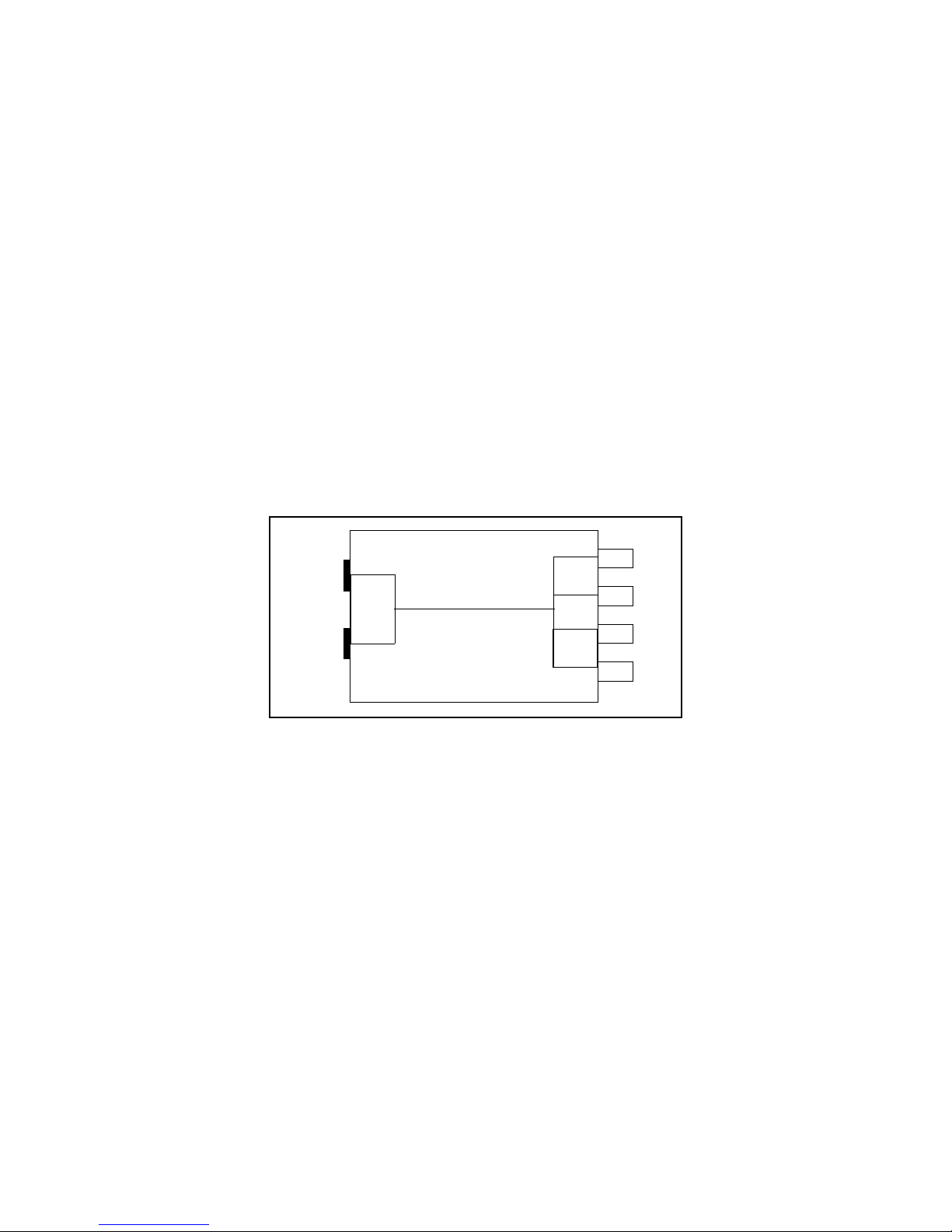
Fibre Channel QIPs Each Fibre Channel QIP (F-QIP) provides connections to four drives
and has two ports out the back. The QIP also provides any-to-any connectivity, so that
every drive (target) is potentially visible to servers through both ports. This permits
flexibility in configuring target visibility: that is, which servers can see which drives.
Figure 2-1 The F-QIP architecture.
For example, the F-QIP can be configured so that Drives 1 and 2 are visible through
Port A, and Drives 3 and 4 are visible through Port B. Or, to consolidate port usage on
a switch, all four drives can be accessed through a single port. In a more complex
configuration, the F-QIP can be configured so that all drives are visible through both
ports; such a configuration is typically used in a shared storage environment or an
environment with failover capabilities. Note that if drives are visible to multiple
servers, your backup software must support this visibility; otherwise server contention
for a single drive can create network and system problems.
Direct-Attach Drives
The Spectra T120 library may communicate with drives using the drives’ direct-attach
SCSI interface. Direct attach is a cost-effective way to gain the benefits of an enterprise
library.
12
Page 13

Chapter 2. Architecture and Configuration Overview
With direct attach, one drive is designated to handle robotic control. That drive is
considered the master drive. In libraries using direct-attach, the robotics are controlled
by the host using SCSI commands sent to the master drive’s LUN 1, while SCSI
commands for the drive are sent from the host through LUN 0. To add more drives to
the library, simply daisy-chain the drives together.
QIP and Daisy-Chaining
If you use one QIP and six drives, you combine cabling methods, so that the QIP
manages four of the drives, with the final two drives daisy-chained into any of the four
other drives connected to the QIP. That drive, on the QIP, does not function as a master
drive for drives chained to it, because robotic control path is handled through the QIP.
Even if a drive goes down, commands are still sent through the board on the drive’s
sled.
Partitions
Partitions divide the library logically, so that the partitioned library looks to the
enterprise environment like one or more physical libraries—one library per configured
partition. The library is partitioned using Shared Library Services™ (SLS) technology
that simplifies storage consolidation through the creation of virtual libraries, each with
its own drives and media.
SLS is a library option that can be added with the purchase of an activation key code
from Spectra Logic. Once SLS is enabled, no external software or hardware tools are
required to manage mixed media within the library. The library can be configured as a
single partition or in multiple partitions. When the library is configured into more than
one partition, each partition exclusively controls the drives and slots assigned to it. The
library requires, at a minimum, one partition. Some of the advantages to running the
library as a single partition include:
• Increased drive availability due to the fact that all drives are available to all backup
processes. For example, if a library has six drives and one partition, data can be
shared across all drives, speeding data backup. If the same library has been split
into two partitions, some drives may be left idle in one partition, while the others
are used for a backup process running in another partition. If you are using directattach for a partition, note that the transmission rate to all drives is limited to the
maximum transfer rate of the SCSI bus.
• No extra costs incurred by software licensing, server requirements, or cabling
complexities.
13
Page 14

Chapter 2. Architecture and Configuration Overview
In some environments, partitioning into multiple virtual libraries is crucial to data
center efficiency and growth. For example, multiple partitions are extremely useful in
the following situations:
• If the environment uses multiple backup software packages, each software package
requires its own dedicated library. Instead of maintaining multiple physical
libraries—one per backup package—the data center can use a single Spectra T120
library with multiple partitions, in which each partition appears to the software as a
dedicated library.
• If a company uses multiple databases, partitioning the library preserves the backup
processes associated with each type of database. For example, if departments
within a company must keep their data segregated, partitioning supplies this
segregation as well as the subsequent integrity of the data set. Each partition has
access only to its own dedicated drives and cartridge locations, and doesn’t mix
cartridges from other partitions into its inventory.
• If multiple protocols are running, such as NDMP and iSCSI, each protocol attaches
to its own library partition in the same physical library.
• If you are using direct-attach, each partition’s master drive (that is, the drive
connected directly from the library to the host, and to which other drives may be
daisy-chained) in each partition can stream data at the maximum transfer rate of the
SCSI bus, so multiple direct-attach partitions transfer data more rapidly.
The benefit of partitioning is that multiple hosts may share the same library robotics,
while dividing the library resources (in this case, the drives and slots). The benefits of
directly attaching drives is that the QIP is eliminated, reducing cost.
Library Management
User Security
Library users are configured for the library in one of three groups, each representing a
level of privileges:
• The superuser group has full permissions.
• The administrator group has all permissions except to create or edit library users.
• The operator group has media handling permissions.
14
Page 15
Chapter 2. Architecture and Configuration Overview
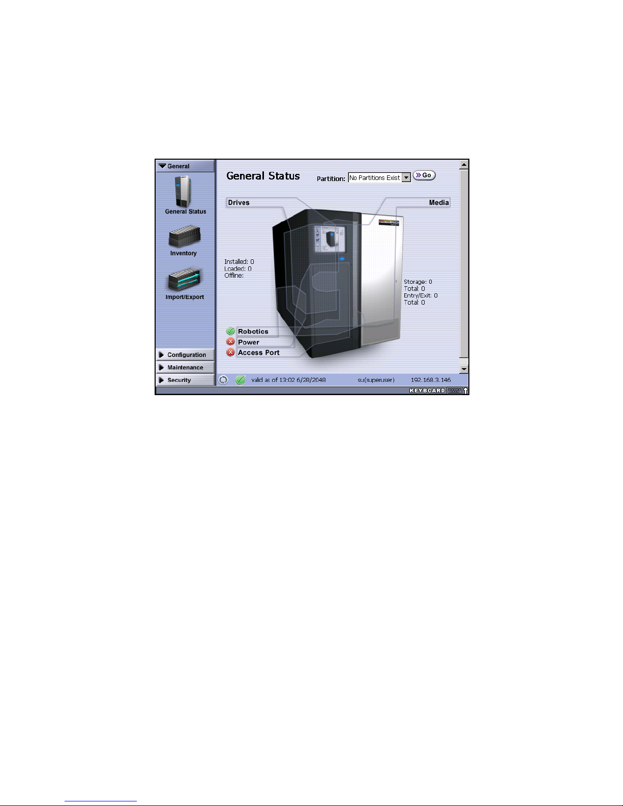
The Library Controller
On the front of the library, the Library Controller (LC) is a large color touch screen with
an intuitive graphical user interface. With the LC, you can configure and maintain the
library and handle all daily operations.
Figure 2-2 The General Status screen of the LC.
Remote Library Controller
The LC supplies a built-in Web server so that the LC can be displayed and operated
remotely in a Web-browser; this remote interface is called the Remote Library
Controller (RLC). The RLC is a free option that is included with every Spectra T-120
library. RLC allows an operator to access the same features and functions that are
available through the LC remotely, excluding only functions involving direct use of the
physical library (for example, the use of the EE port).
15
Page 16

Chapter 2. Architecture and Configuration Overview
Expansion and Upgrades
The Spectra T120 library is designed to transform and expand to meet a data center’s
changing storage requirements, as well as to achieve storage consolidation goals.
Additional Spectra T120 libraries may be purchased and stacked for added storage.
Make sure to plan ahead and take the library’s expansion capabilities into
consideration when you install and configure the library. Use its capabilities as
appropriate to implement long-term strategic storage plans.
Capacity
CoD is the library’s capacity-on-demand feature. It lets users purchase a library that
suits their current needs, and lets them purchase additional capacity later as required.
This reduces up-front costs, because users only pay for what they currently need. As
more capacity is required, it can be added in increments—users purchase key codes to
activate slots in the library and purchase additional media to fill the added slots. These
purchases can be made through a sales representative or directly through the Spectra
Logic Web site.
Throughput and Connectivity
The library’s QIPs can be switched out at any time to change the library’s connectivity
type. Adding an additional drive will also increase the library’s drive throughput.
Tape drives and QIPs are sled-mounted and install in under two minutes.
Power Supplies and USBs
You may order and install additional power supplies for failover and redundancy.
One free USB storage device is included with every Spectra T120 Library purchase. You
may elect to purchase additional USB storage devices that you can use when upgrading
the Spectra T120 library’s firmware, or as a troubleshooting tool for use as instructed
by Spectra Guard™ Technical Support.
16
Page 17

3 Unpacking and Installation
Overview
The following sections describe steps involved in unpacking and initial library
configuration:
• Unpacking, below
• Noting the Components to be Installed on page 22
• Mounting the Library into the Rack on page 23
• Powering On on page 29
• Interpreting the Library Controller on page 32
General information about library architecture and concepts—including QIPs, drive
visibility, and other partition fields—is discussed in Chapter 2. Architecture and
Configuration Overview.
Unpacking
Overview
Time estimates for unpacking, installing, and configuring the library:
• Unpacking the Spectra T120 library takes less than 30 minutes.
• Installing and configuring the library takes less than two hours.
• Mounting the library in a rack takes under 30 minutes.
Material and tools you need to unpack and install the library:
• A #2 Phillips screwdriver
• A pair of scissors
17
Page 18
Chapter 3. Unpacking and Installation
Tip n Tell
Shockwatch
Preparing the Unpacking Location
Note: Make sure that you have a work space area prepared before you
remove the library from the crate
Set the crate in a location that gives you 10 feet of access at the both the front and back
to safely unpack the library. Once the library is out of the crate, move the library to a
work space where you have access to all four sides.
\
Note: Make sure the library is set up so that the socket-outlet is installed
near the equipment and is easily accessible.
Unpack the Library
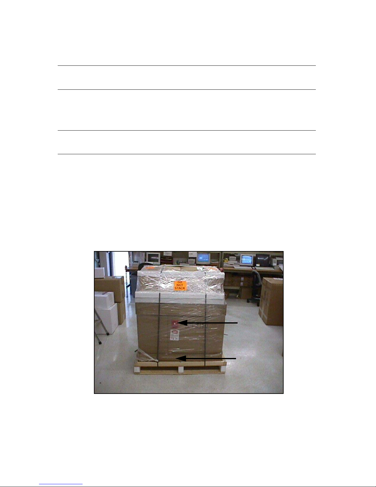
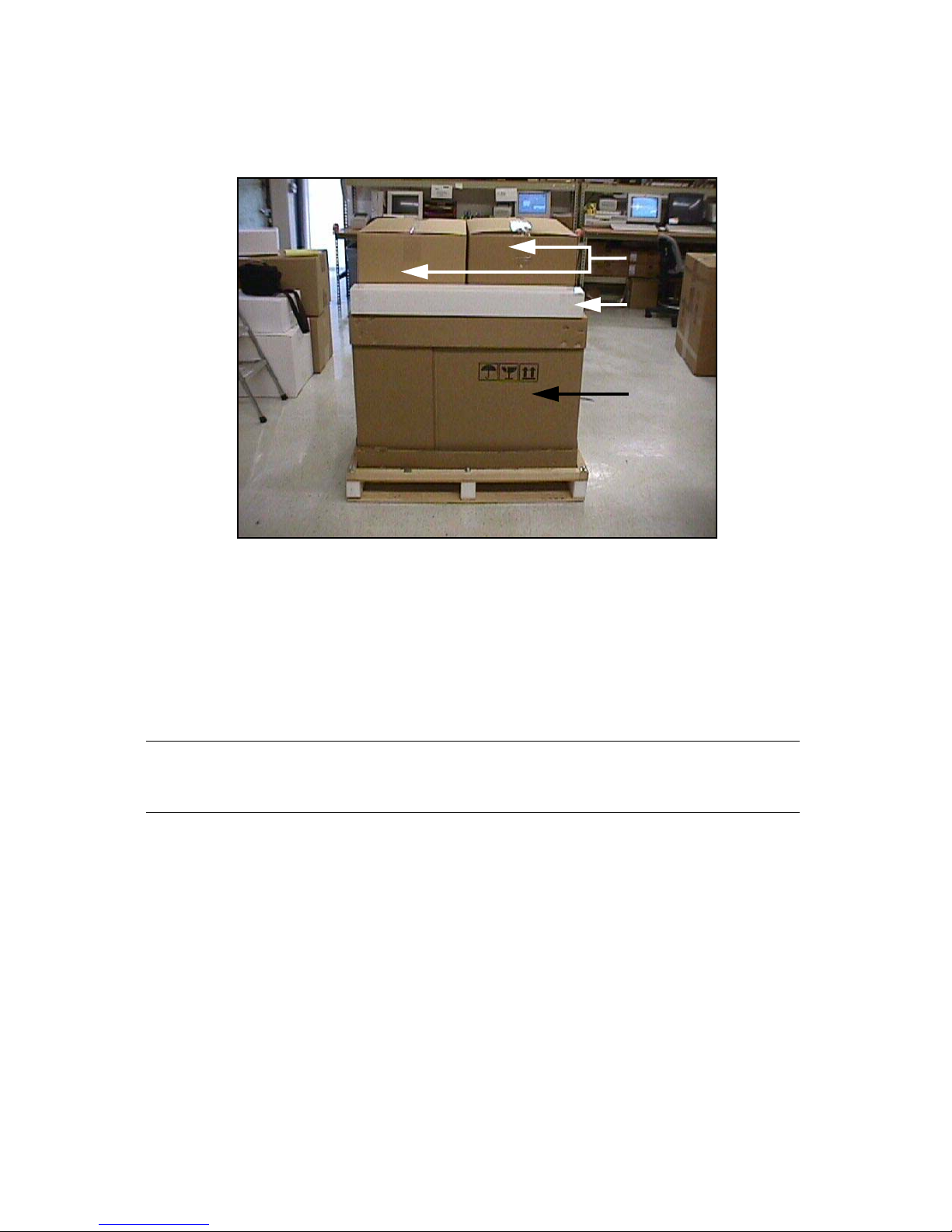
1. Use scissors to cut away the plastic wrap surrounding the library and its crate.
2. Check the Tip n Tell and Shockwatch
improperly handled, before proceeding (Figure 3-1).
The Tip n Tell is located on the side of the library; the Shockwatch is located on
the side of the library near the bottom.
®
to ensure that the crate has not been
Figure 3-1 Check Tip n Tell and Shockwatch.
18
Page 19
Chapter 3. Unpacking and Installation
Caution: Do not unpack the library if Tip N Tell or Shockwatch has been
tripped. Contact both the shipping company and Spectra Logic.
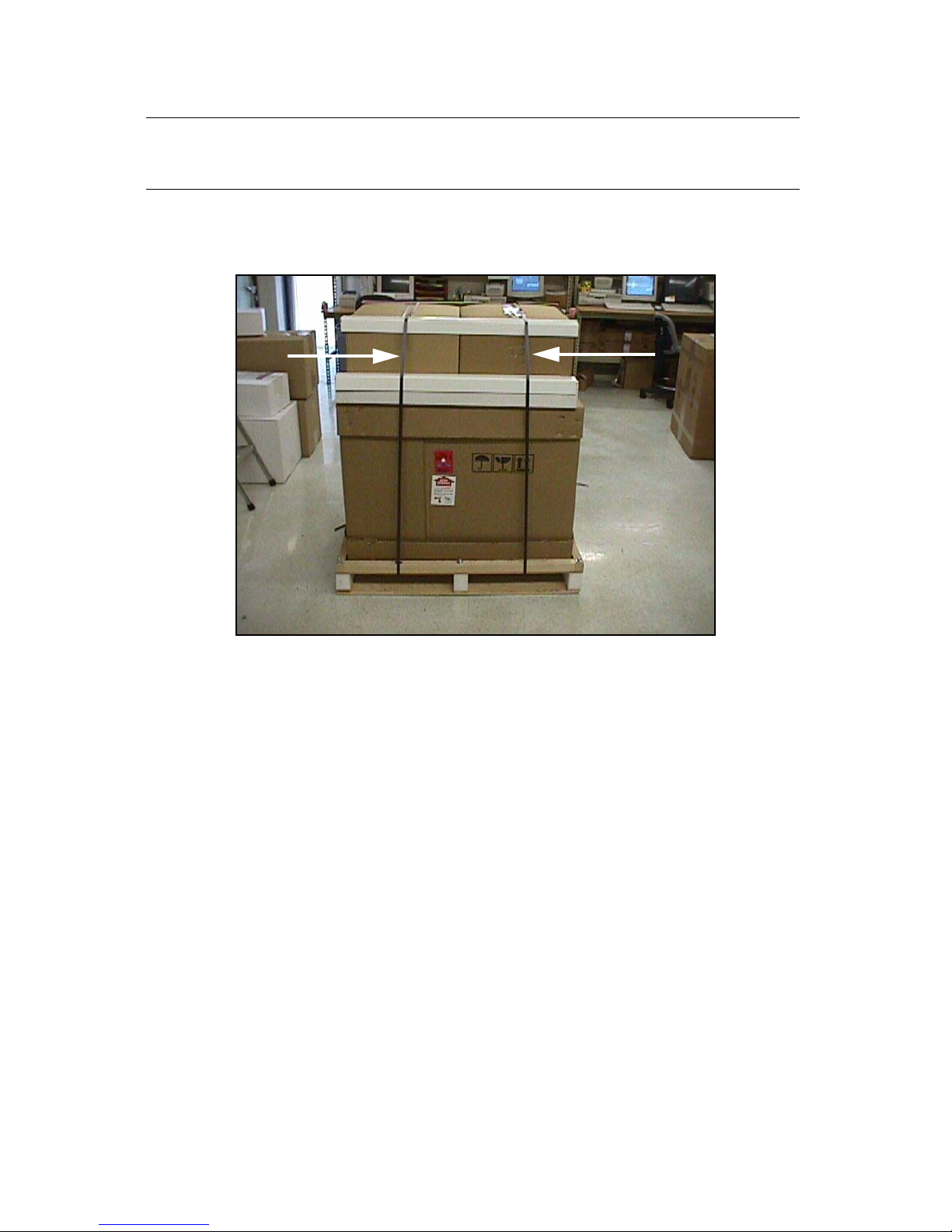
3. Use the scissors to cut the plastic bands holding the library and its boxes to the
crate (Figure 3-2).
Figure 3-2 Cut the plastic bands.
19
Page 20
Chapter 3. Unpacking and Installation
Drive Boxes
Rail Kit
Library
4. Remove the protective cardboard corners, and set aside the drive box(es) and
rail kit (Figure 3-3).
Figure 3-3 The library with the drive boxes and rail kit identified.
5. Remove the top and sides of the box used to enclose the library.
6. Remove the protective foam corners and lift the plastic cover off of the library.
7. Lift the library out of the crate and move the library to a work space where you
have access to all sides of the library.
Warning: The library is heavy, 160 lbs. (72.57 kg) when empty. Use three
people to help move the library.
Remove the Internal Packaging
1. Locate the library key, which is stored in a bag attached to the top of the library.
2. Use the key to unlock and open the front door of the library.
20
Page 21
Chapter 3. Unpacking and Installation
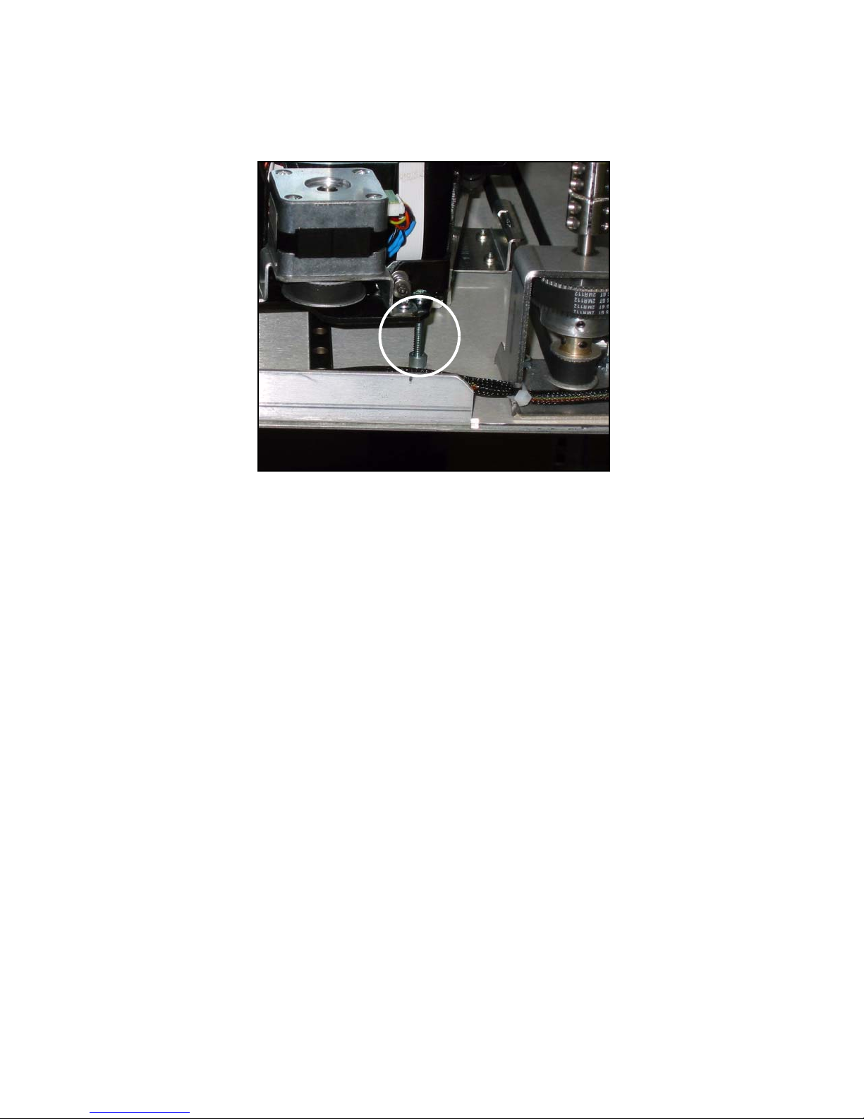
3. Open the front door and remove the shipping screw holding the robotic picker
in place.
Figure 3-4 The shipping screw.
4. Re-attach the shipping screw to its storage location, located about two inches in
front of the shipping location. Keep the screw here in case you need to move
the library again.
5. Close and lock the front door.
21
Page 22

Chapter 3. Unpacking and Installation
Noting the Components to be Installed
Each library is unique, depending on the specific configuration ordered. At a
minimum, your library has at least one drive. Unpack and identify the components that
shipped with the library. You typically won’t have all of the components listed below.
Drives
The Spectra T120 library supports multiple types of media and drives, including:
•LTO-2
• SAIT
Power and Connectivity Cables
Set aside the power cable and any connectivity cables that are shipped with the
components for later installation.
Quad Interface Processors (QIPs)
QIPs are library controllers, which are optional in the Spectra T120 library.
F-QIP The Fibre Channel QIP (F-QIP) provides a Fibre-Channel-to-SCSI interface
between the host and the tape drives. It uses two Fibre Channel ports—either optical
or copper, depending on the interface adapter. Each port controls up to four tape
drives.
G3 E-QIP The Generation 3 Gigabit Ethernet QIP (G3 E-QIP) provides a gigabit ethernet
interface between the host and the tape drives.
Check List
It may be helpful to note in the chart below the cables, drives, and QIPs that you have
unpacked.
SCSI Cables Power Cable SAIT Drives LTO Drives F-QIP G3 E-QIP
Quantity
22
Page 23
Chapter 3. Unpacking and Installation
Mounting the Library into the Rack
Note: If you’re not rack mounting the library, go to page 29.
Warning: Do not load the library components until after it is installed in
the rack. The library weighs 160 lbs. (72.57 kg) when empty.
Use at least three people when moving the library.
Materials and Tools Required
Tools:
• A #2 Phillips screwdriver
• An adjustable wrench
• A tape measure
The rack mount kit that shipped with the library, which includes:
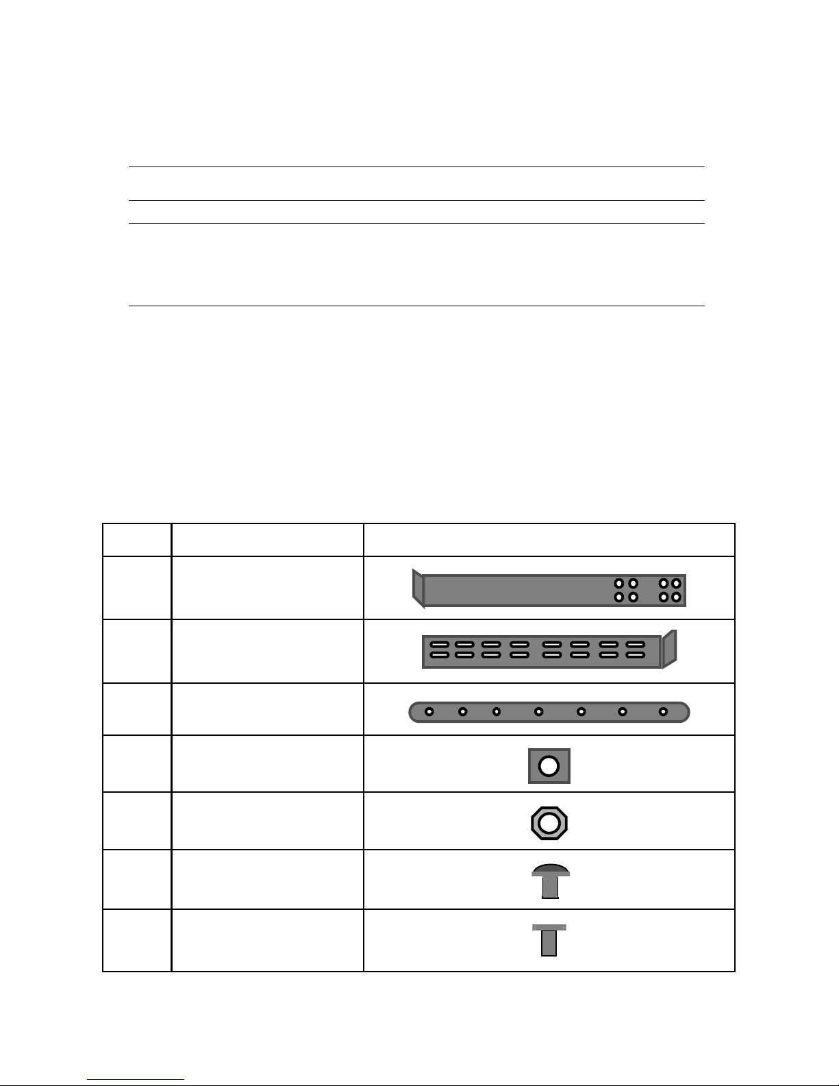
QTY Description Part
2Rails:
2 Extension brackets:
2 Sliders:
22 10-32 clip-on nuts:
8 10-32 nuts:
31 10-32 x 1/2-inch screws:
8 Countersink screws:
23
Page 24
Chapter 3. Unpacking and Installation
Library
Height-24.5”
Library
Depth- 35”
Library
Width-17.5”
Preparing the Library
Install Sliders
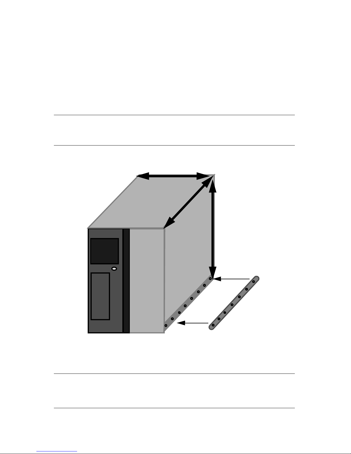
1. Use the two sliders and fourteen 10-32 x 1/2-inch screws.
2. Attach a slider to both sides of the library near the bottom.
Note: There are eight holes on the bottom of the library and seven holes
on the slider. Attach the slider to the holes closest to the back of
the library.
Figure 3-5 Library dimensions and location of one slider.
Caution: With LTO drives the depth is 36.5 in. (92.71 cm); with SAIT
drives the depth is 40.25 in. (102.24 cm). Your rack must support
these depths. A depth of 43 in. is recommend for enclosed racks.
24
Page 25
Chapter 3. Unpacking and Installation
Library Bottom
Rail
installed
offset.
Preparing the Rack
Caution: Make sure that the rack has at least 3 ft. of access at both the
front and back for further installation and later maintenance.
1. Referring to Figure 3-7, step 1, measure the depth of your rack. Then attach one
rail to one rail extension bracket using four flat-head screws and four 10-32 nuts
at the required depth. Repeat this for the second rail.
2. Referring to Figure 3-7, step 2, use eight 10-32 x 1/2-inch screws and eight clip-
on nuts. Attach the rails to the rack at the desired height with two screws
attaching the ends of each rail to the rack. Only attach the bottom two holes of
the rail to the rack.
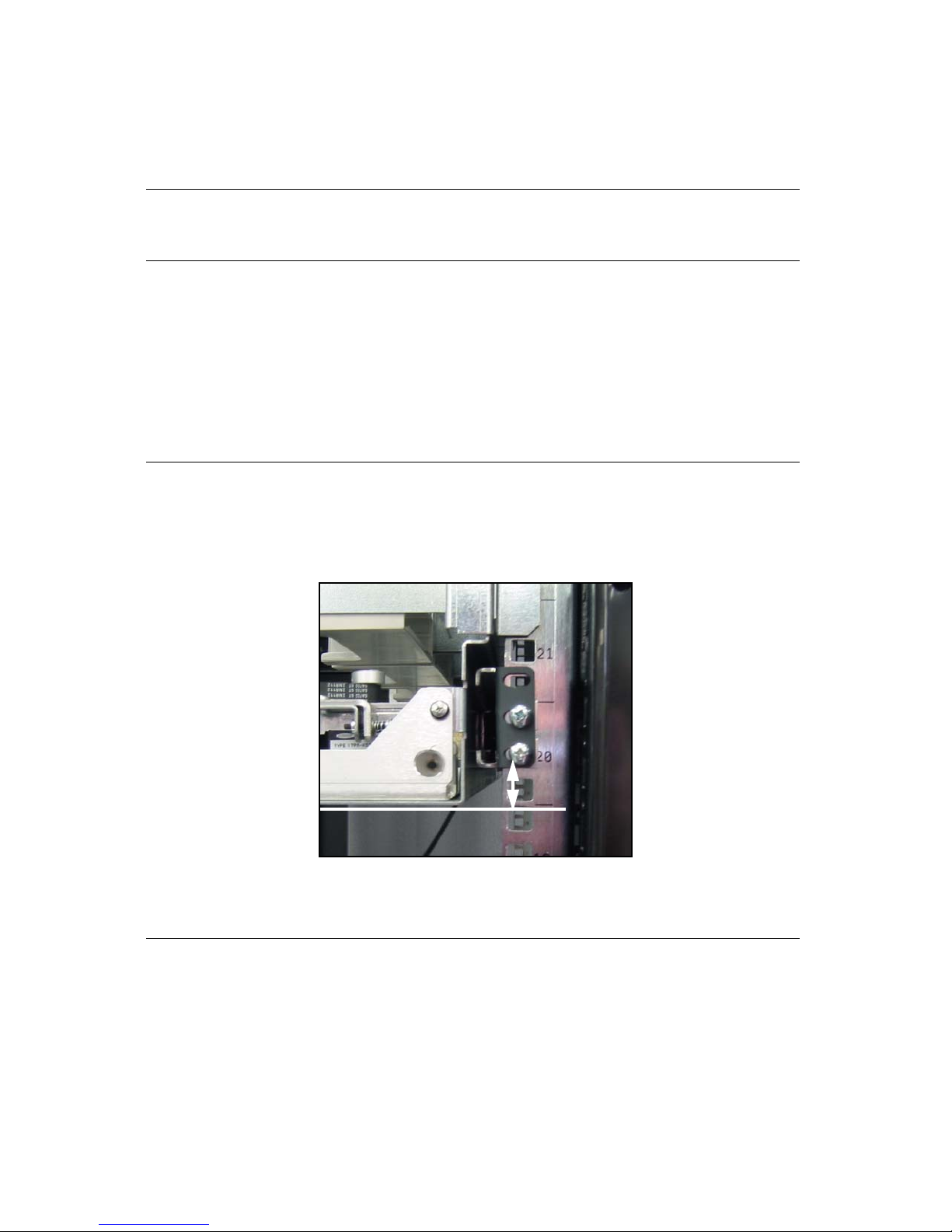
Note: The library bottom sits one notch below the lowest part of the rail.
Therefore, the rail must be installed offset by one notch, as shown
in Figure 3-6. If you do not offset the rails, the library hole
alignment will be off.
Figure 3-6 The rail installed offset with two screws.
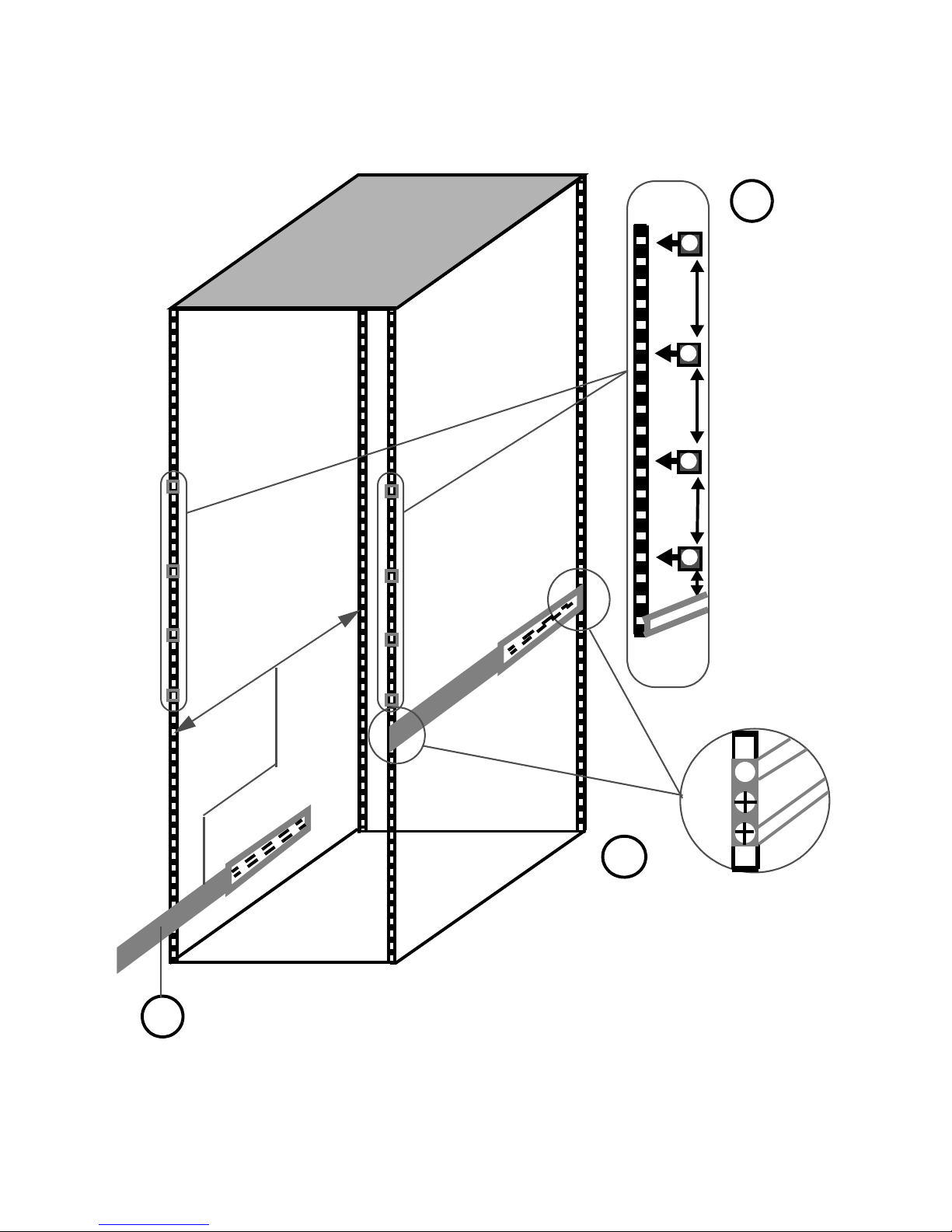
3. Attach four clip-on nuts on both sides of the front rack posts prior to installing
the library into the rack. Install the first clip-on nut 2 inches above the top of the
installed rail. Install the next clip-on nut 5 1/4 inches above that (measured from
the center of the preceding clip on nut). Install the next clip-on nut 7 5/8 inches
above that and the last clip-on nut 5 1/4 inches above that. Refer to Figure 3-7,
step 3. The clip-on nuts attach the front of the library to the rack and cannot be
installed after the library is in the rack.
25
Page 26
Chapter 3. Unpacking and Installation
Adjust the rails and extension brackets to the depth of your rack. Then,
attach them together with four flat-head screws and four nuts at that depth.
Attach rails to the rack using two screws and
two clip-on nuts. NOTE–The rails need to be
installed offset see Figure 3-6.
Place four clipon nuts on both
sides of the front
rack posts prior
to installing the
library into the
rack. The clip-on
nuts attach the
front of the
library to the
rack. Install the
first clip-on nut
2” above the
rails.
Subsequent clipon nuts are
measured from
the center of the
preceding clipon nut
2”
5 1/4”
7 5/8”
5 1/4”
1
3
2
(Not to scale)
Figure 3-7 Detail of the prepared rack prior to installing the library.
26
Page 27
Chapter 3. Unpacking and Installation
Install the Library Into the Rack
Warning: The library is heavy, 160 lbs. (72.57 kg) when empty. Use three
people to help move the library into the rack.
Warnung: Die Library hat ein sehr hohes Gewicht. Bewegen Sie sie nur
mit Hilfe wenigstens drei Personen und vermeiden Sie, die
Library zu kippen.
1. Align the library sliders with the rails and slide the library into the rack.
2. Once the library is in the rack, locate the library door key and open the library
door.
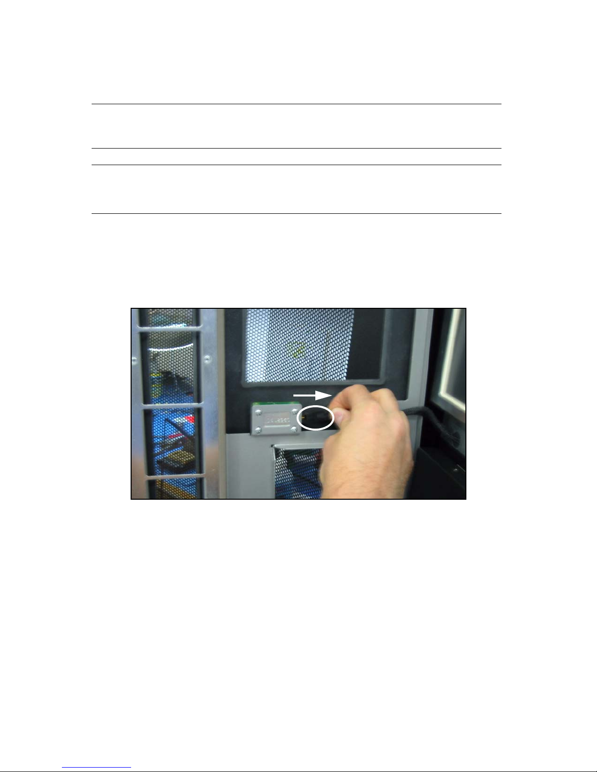
3. Disconnect the power switch cable from the door (Figure 3-8).
Figure 3-8 Inside of library door with the power switch cable disconnected.
27
Page 28
Chapter 3. Unpacking and Installation
4. Next, locate the spring hinge on the upper left hand side of the door, and pull
down (Figure 3-9).
Figure 3-9 The library spring hinge.
5. With the spring hinge down, pull out on the library door and lift it up off the
bottom door hinge and set the door safely aside.
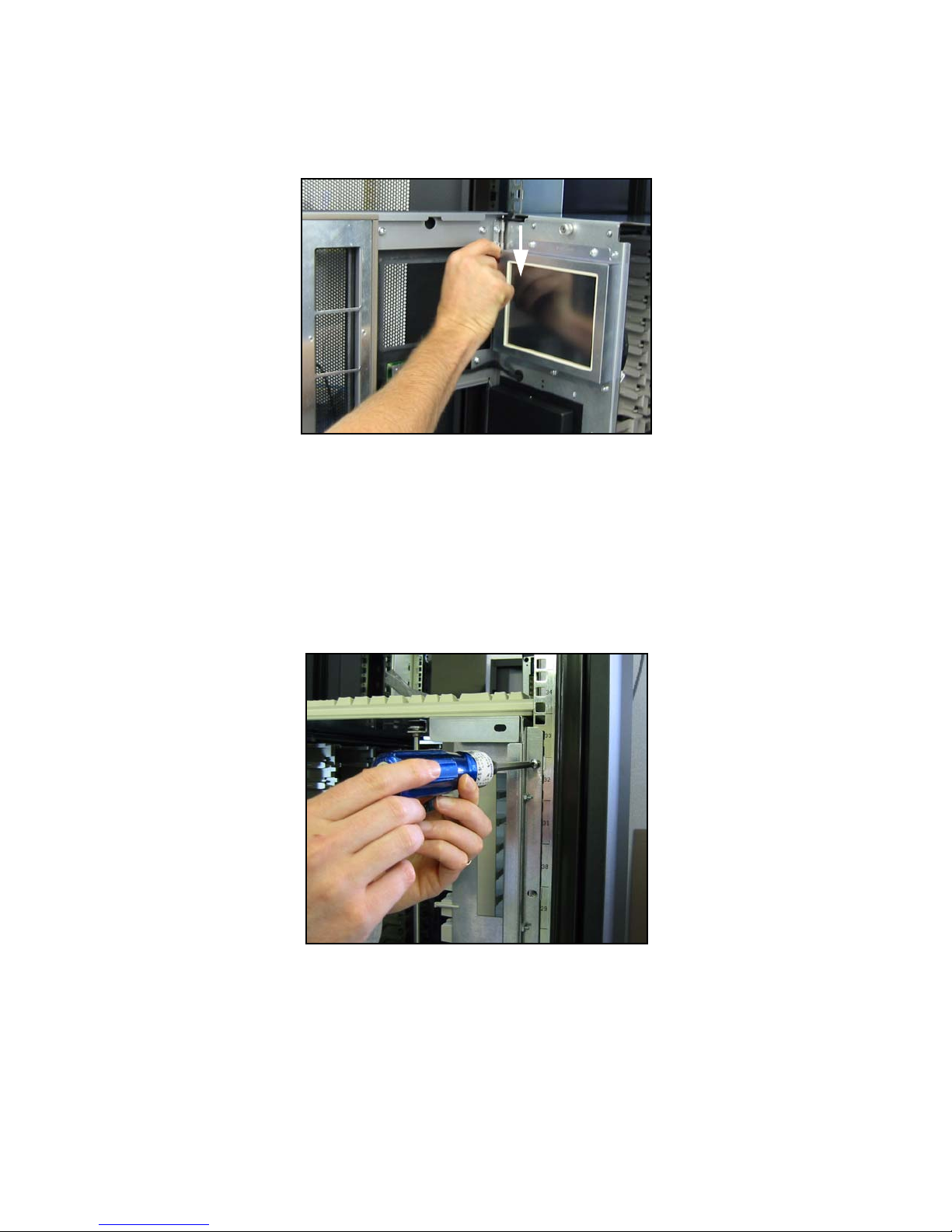
6. Locate eight 10-32 x 1/2-inch screws and use them to attach the library to the
rack (Figure 3-10). The holes on the library should match up with the clip-on
nuts you installed previously. See Figure 3-7, step 3.
Figure 3-10 Attach Library.
7. Once the library is secure, re-install the door, and re-connect the power switch
cable.
8. Close and lock the front door.
28
Page 29
Chapter 3. Unpacking and Installation
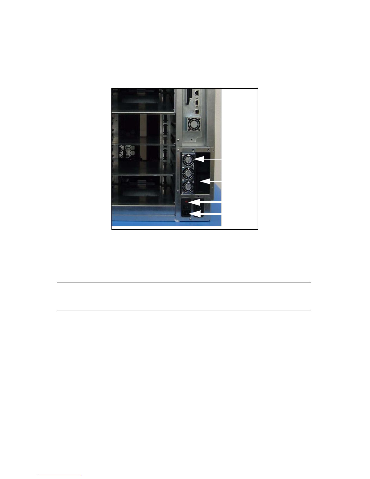
Power switch
Power inlet
Space for
additional
power supply
Power supply
Powering On
1. Locate the power inlet and power switch on the rear of the library (Figure 3-11).
Figure 3-11 Location of the power inlet and the power switch.
2. If you purchased an additional power supply for redundancy, install it now. If
you do not have an additional power supply, go to Step 3.
Caution: If two power supplies are installed they must connect to
different branch circuits.
To install the additional power supply:
i. Use a #2 screwdriver to remove the cover plate to the right of the installed
power supply.
ii. Remove the power supply from its protective packaging and insert it into the
slot.
iii. Using a #2 screwdriver, attach the power supply to the library.
3. Connect the provided power cord to the left inlet position and then connect it to
the power source. If you have an additional power supply connect the additional
power cord to the right inlet position and then to the power source.
4. Move power switch(es) to the On position.
29
Page 30
Chapter 3. Unpacking and Installation
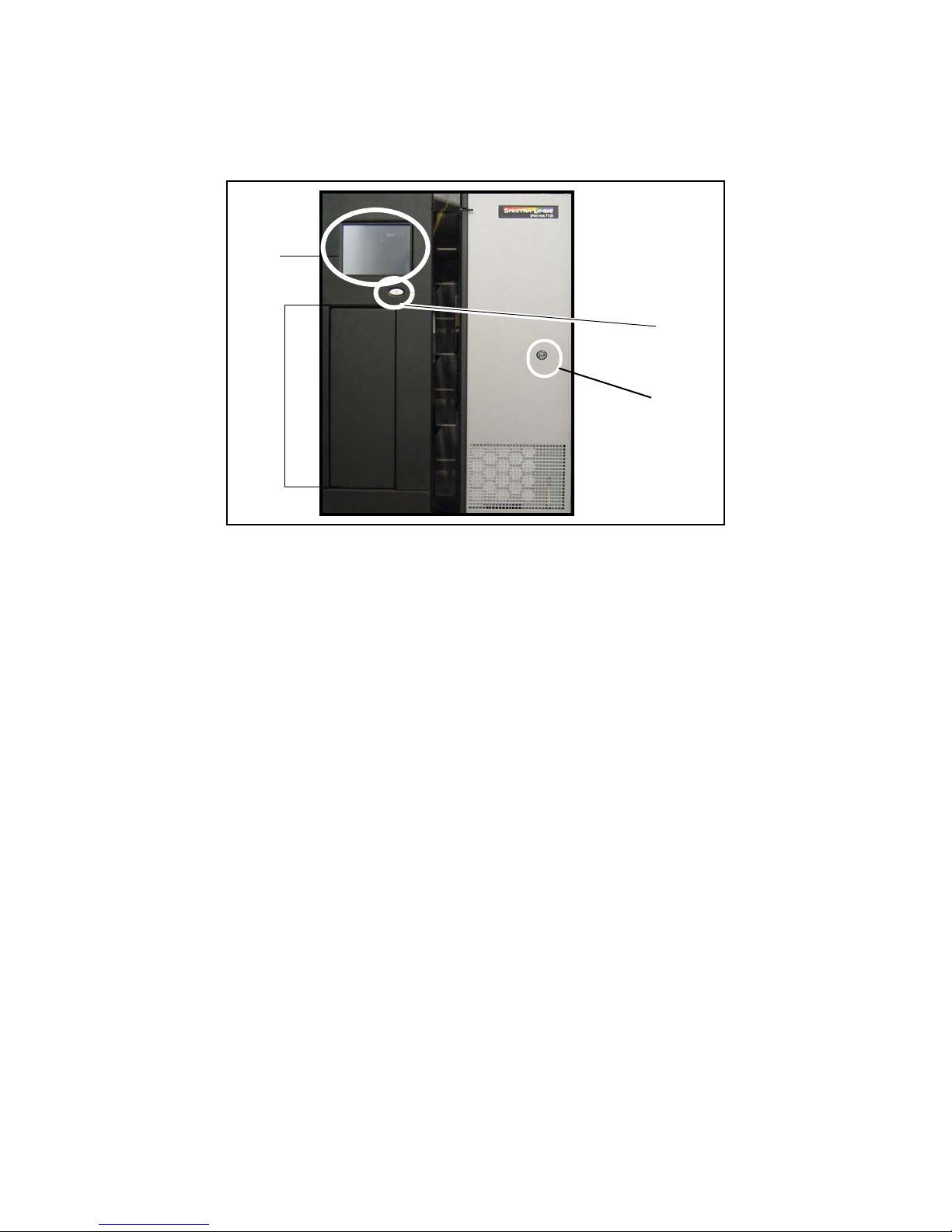
Library
Controller
Soft
power
button
EE port
Library
lock
5. Press and hold the soft power button (Figure 3-12) for two to three seconds or
until the blue light on the button changes state.
Figure 3-12 The library’s front panel and soft power button.
The power-on sequence begins; this process takes about five minutes while the library
initializes all components.
30
Page 31

Chapter 3. Unpacking and Installation
Logging In for the First Time
As the library initializes, the LC’s main login screen appears (Figure 3-13).
Figure 3-13 The LC’s main login screen, with the Keyboard icon called out.
1. Select the screen’s Keyboard icon; a keyboard displays on the bottom of the front
panel.
2. Select the User field; a cursor appears.
3. Use the keyboard to type su.
Note: Until a password is set, no password is required.
4. Select Login. The library displays the General Status screen, shown in
Figure 3-14 on page 32.
31
Page 32

Chapter 3. Unpacking and Installation
Current
toolbar
Other
toolbars
Refresh
Messages
Time of last refresh
Current user
Library’s IP address
(or name)
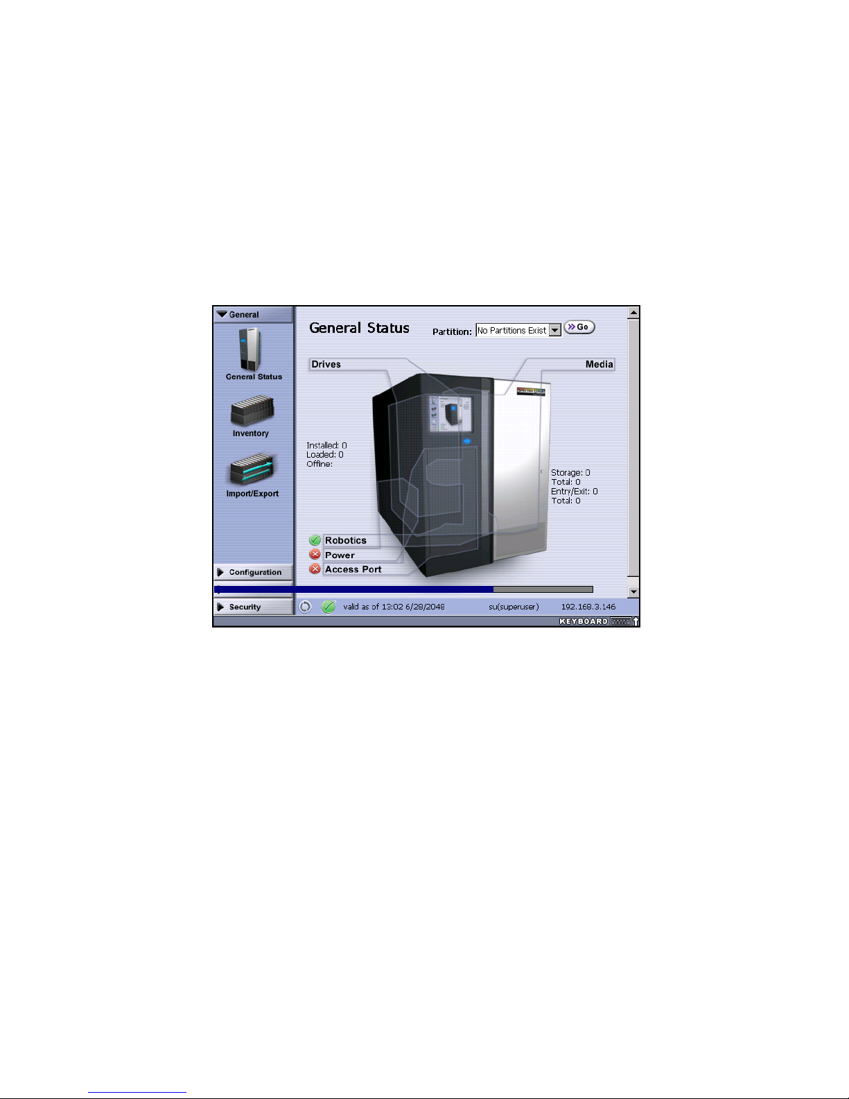
Interpreting the Library Controller
After you log in and the library finishes initializing, the LC displays the library’s
General Status screen (Figure 3-14).
The LC on the library’s front panel is a touch screen. When accessed using the Remote
Library Controller (RLC), you can select the toolbars and icons using the mouse and
keyboard attached to your computer.
Caution: Sharp or metal objects can damage the LC.
Toolbars
Use the interface toolbars to navigate the LC. After you have logged on, the LC displays
a toolbar on the left at all times—either the General toolbar (shown in Figure 3-14), the
Configuration toolbar, the Maintenance toolbar, or the Security toolbar. By selecting
from the list at the top or bottom of the toolbar, you can change toolbars at any time.
Figure 3-14 The General Status screen.
More advanced functions are accessed through the Configuration, Maintenance, and
Security toolbars and their respective options. The full suite of LC functions are not
available until after the library has been configured.
32
Page 33
Chapter 3. Unpacking and Installation
The General toolbar provides access to the most commonly used screens and
functions: General Status, Inventory, and Import/Export.
Progress Bars
If a horizontal progress bar displays along the bottom third of the screen (Figure 3-15),
the library is busy processing a command. Do not use the touch screen until the
progress bar disappears.
Figure 3-15 Progress bar indicating that the library is busy.
33
Page 34

Chapter 3. Unpacking and Installation
34
Page 35

Chapter 4. Installing and Cabling Components
4 Installing and Cabling Components
Overview
The following sections describe steps involved in initial library configuration:
• Installing Components on page 36, which includes:
• Installing QIPs on page 37
• Installing Drives on page 40
General information about library architecture and concepts—including QIPs and
drives—is discussed in 2 Architecture and Configuration Overview.
35
Page 36
Chapter 4. Installing and Cabling Components
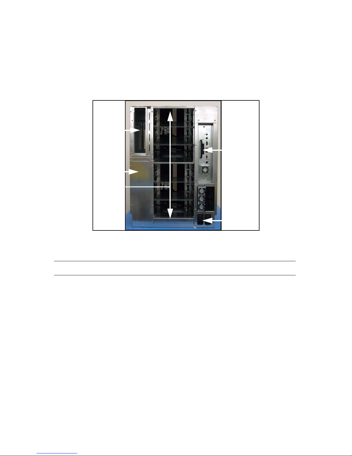
Power supply
Library Control
Module (LCM)
QIP bay
QIP cover
plate
Power
switch
Drive bays
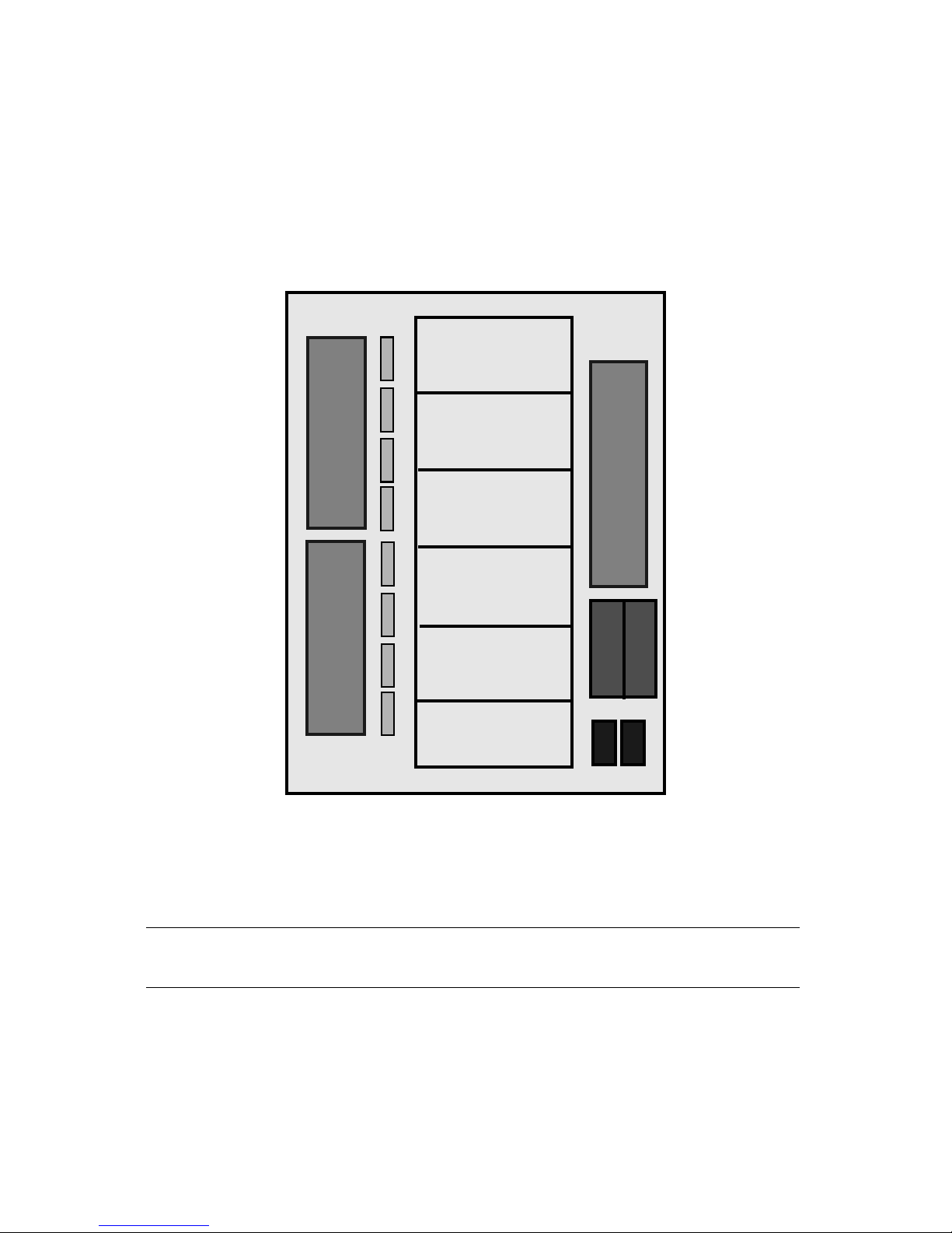
Installing Components
Review the Noting the Components to be Installed on page 22 that lists the components
shipped with the library. The following diagram (Figure 4-2) of the back of the library
shows where to install the QIPs and drives
Figure 4-1 The back of the library.
Note: The library arrives with the LCM and one power supply installed.
36
Page 37
Chapter 4. Installing and Cabling Components
Drive slot 1
Drive slot 2
Drive slot 4
Drive slot 5
Drive slot 6
Drive slot 3
4
3
2
1
4
3
2
1
QIP
slot 2
QIP
slot 1
BUS
BUS
Component Locations
Every QIP, QIP bus, and drive has a location number and is numbered from the bottom
up. You will need to know the component location when you are configuring the
library. Though it is not necessary, it may be helpful to install components logically,
i.e., if you have one QIP and two drives, you would want to install the QIP in QIP slot
1 and the drives in drive slots 1 and 2.
Installing QIPs
Note: It is not necessary to run a Spectra T120 library with a QIP. If you
1. Remove the QIP by the handle from the anti-static bag. Set the QIP aside for
placement into the library.
Figure 4-2 QIP, QIP bus, and drive locations.
do not have a QIP to install, go to Installing Drives on page 40.
37
Page 38
Chapter 4. Installing and Cabling Components
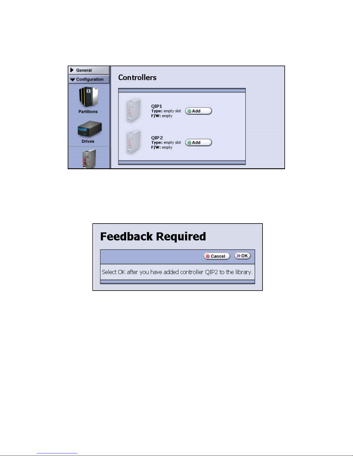
2. Go to the LC. Make sure you are logged in as an administrator or super user.
Select Configuration > Controllers. The Controllers screen appears (Figure 4-3).
Figure 4-3 The Controllers screen.
3. Select Add next to the location where you intend to place the QIP. A feedback
window appears, as shown in Figure 4-4.
Figure 4-4 The Feedback Required screen.
4. Remove the foam pin protector from the connector on the back of the QIP, and
insert the QIP into QIP slot 1 and push it firmly in.
38
Page 39

Chapter 4. Installing and Cabling Components
5. Return to the LC, then select OK. The library now recognizes the QIP
(Figure 4-5).
Figure 4-5 The Controllers screen, showing F-QIP1 installed.
Note: Each QIP supports up to four drives. If you have 2 QIPs, you may
set up the bottom QIP to handle the adjacent four drives, and the
top QIP to handle the top two drives, or alternately, set up each
QIP to support three adjacent drives.
6. If there is another QIP to install, repeat Step 3 through Step 5.
39
Page 40

Chapter 4. Installing and Cabling Components
Installing Drives
Drives are numbered starting with Drive 1 in the bottom slot. Users typically choose to
load the drives from the bottom slot up.
1. Locate the drive to be installed. Hold the drive sled by the handle and remove it
from its anti-static bag. Set the drive aside for later placement into the library.
2. From the LC, select Configuration > Drives. The Drives screen appears
(Figure 4-6).
Figure 4-6 The Drives screen.
40
Page 41

Chapter 4. Installing and Cabling Components
3. Select Add next to the location where you intend to place the drive. The Drive
Cabling screen appears.
Figure 4-7 The Drive Cabling Screen.
4. Choose one of the following three options for cabling the drive.
Caution: Do not cable or insert the drive yet. Only choose the method of
cabling from the following options.
41
Page 42

Chapter 4. Installing and Cabling Components
To ho st
SCSI terminator
i. Host (directly connected to another machine)
• If you do not have a QIP, directly attach the drive to a host. To do this you
will simply attach a SCSI cable directly to the drive from the host as
outlined in Cabling a Direct-Attach Drive on page 61. Make sure that you
properly terminate the SCSI bus on the drive.
• Example: Connect the drive in Drive slot 1 to the host.
Figure 4-8 Drive 1 directly attached to the host.
• You can directly attach up to six drives.
• You can also daisy-chain drives. For more on daisy-chaining, see Step iii
on page 44.
42
Page 43

Chapter 4. Installing and Cabling Components
18-inch SCSI cable
attached from Drive
1 to QIP 1 Bus 1
SCSI terminator
Connect to
host or switch
ii. Connected to QIP:
• If you have a QIP, you can cable the drive directly to the QIP by attaching
the drive to the one of the four bus locations using the 18-inch SCSI cable
provided. (See page 37, to view component locations).
•Example:
Connect the drive in Drive slot 1 to QIP 1, Bus 1
Figure 4-9 Drive 1 connected to QIP 1 bus 1.
• You can connect up to four drives directly to one QIP. Additionally, you
can daisy chain up to two more drives into one (or two) of the QIP
attached drives for a maximum of 6 drives. For more on daisy-chaining,
see Step iii on page 44.
43
Page 44

Chapter 4. Installing and Cabling Components
Drives 1-3 attached
to QIP 1 buses 1-3
respectively. All
properly terminated.
Drive 4 attached to
QIP 1 bus 4. Drive 5 is
daisy-chained to drive
4 and properly
terminated.
Connect to host
or switch.
iii. Daisy-chain:
• Whether you have a QIP or direct-attached drives, or both, you can also
daisy-chain additional drives.
• Example:
Connect the drive in drive slot 5 to the drive in drive slot 4.
Figure 4-10 Drive 5 daisy-chained to drive 4.
• You can daisy chain as many as five drives as long as one drive is attached
to either a QIP or directly attached to a host.
Note: When daisy-chaining, select the same connection for the daisy-
chained drive as you chose for the source drive. It can be either
Host or Connected to QIP depending on the source drive. In the
example above, drive 4 is attached to QIP 1 bus 4. So, designate
drive 5 as attached to QIP 1 bus 4.
5. Once you have decided on the appropriate connection for your drive, select
either Host or Connected to QIP:
i. If you select Host, select the SCSI bus you wish to use. Make sure that you
don’t select a bus that is already in use by the host.
ii. If you select Connected to QIP, select the QIP and bus. Make a note of which
QIP and which bus you selected.
6. Select Next. A Warning screen displays.
7. Select Next again. A Feedback Required screen appears.
44
Page 45

Chapter 4. Installing and Cabling Components
8. Go to the back of the library and add the drive to the appropriate slot. Cable it
to match your selection in Step 5.
9. Once the drive is securely in place and cabled, go back to the LC and select OK
on the Feedback Required screen. A feedback window will appear. Once the
library refreshes, the drive is now added to the library (Figure 4-11).
Figure 4-11 LTO1 in the Drives screen.
Note: If you have two types of drives, make sure that you load all of one
type before installing the second type of drive.
10. Repeat these steps for each drive to be installed.
45
Page 46

Chapter 4. Installing and Cabling Components
46
Page 47

5 Partitioning and Connecting to a Host
The following sections describe steps involved in connecting the library to a host and
partitioning the library:
• Partitioning a Library with Direct-Attach Drives on page 47
• Partitioning a Library with an F-QIP on page 51
General information about library architecture and concepts—including QIPs, drive
visibility, and other partition fields—is discussed in Chapter 2. Architecture and
Configuration Overview.
Partitioning a Library with Direct-Attach Drives
After you’ve installed components and cabled the library, create at least one library
partition.
• If your library uses a QIP, proceed to Partitioning a Library with an F-QIP
on page 51.
• If your library uses direct-attach, continue.
Initial Partition Setup
Before you use the LC to create the direct-attach partition, identify:
• The name of the partition.
• The drive to be used for robotic control, which can be any drive.
• The number of drives to be assigned to this partition. If the library uses only one
partition, select all listed drives.
47
Page 48

Chapter 5. Partitioning and Connecting to a Host
1. Make sure that you are logged in as a user with superuser or administrator
privileges. To change user types, select Security > Switch User, then log in as a
new user.
2. Select Configuration > Partitions. The Shared Library Services screen appears
(Figure 5-1).
Figure 5-1 The Shared Library Services screen.
3. Select New. The Name and Media Type screen (Figure 5-2) appears.
Figure 5-2 The Name and Media Type screen.
4. Enter a unique name for this partition in the Name field.
5. Select the media type for this partition, then select Next.
Note: As necessary or as directed by Technical Support, you can create
your own emulation and device ID setting. Although not
recommended, this option is available and described in Advanced
Configuration Settings on page 59.
48
Page 49
Chapter 5. Partitioning and Connecting to a Host
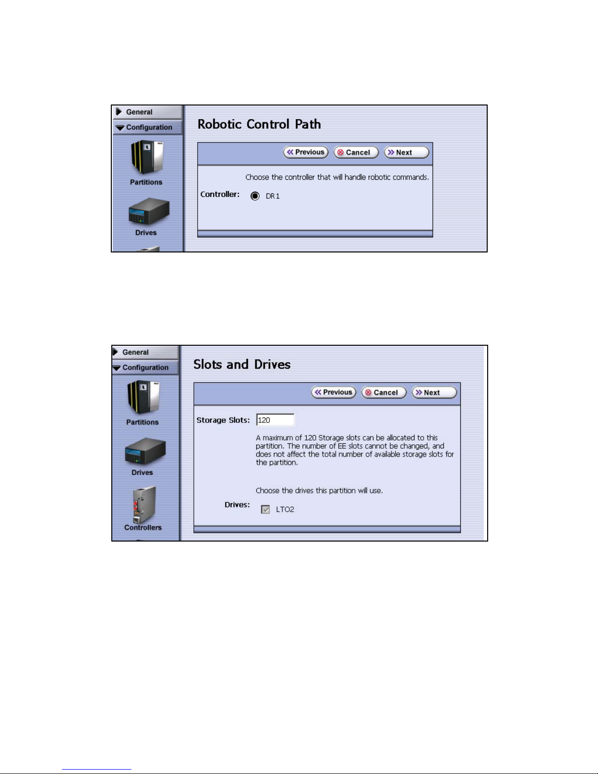
6. Review the Robotic Control Path screen, and select the drive to receive and
process robotic commands (Figure 5-8). Then select Next.
Figure 5-3 The Robotic Control Path screen.
Configuring and Saving Settings
1. The Slots and Drives screen (Figure 5-4) appears.
Figure 5-4 The Slots and Drives screen.
2. Use the Slots and Drives screen to enter the number of storage slots to assign to
this partition. When creating a single partition, make sure to assign all available
slots and drives to this partition.
3. Check the box next to each listed drive to be dedicated to this partition. If the
library has only one partition, make sure all drives are selected.
49
Page 50

Chapter 5. Partitioning and Connecting to a Host
4. Select next, the Save Partition screen appears (Figure 5-5).
Figure 5-5 The Save Partition screen.
5. Review the data and confirm that all settings are correct for this partition.
• If the configuration is correct, proceed to Step 6.
• If the configuration is not correct, either:
•Select Cancel to configure the partition again from the beginning.
•Select Previous to go backwards through the configuration screens and
edit specific aspects of the partition.
Note: If you use Previous to edit your settings, note your configuration
data, so that you can re-enter the data as you move forward again
through the screens.
6. Select Save. The library requires several minutes to store the configuration
information, after which the Shared Library Services screen displays (Figure 5-13
on page 57) showing the new partition.
7. Go to Cabling a Direct-Attach Drive on page 61, to connect to a host.
50
Page 51

Chapter 5. Partitioning and Connecting to a Host
Partitioning a Library with an F-QIP
Preparing for the Partition
Before configuring a partition for a library with a QIP, follow the procedures in this
section.
1. Identify:
• The name of the partition
• The drives visible to the library robotics (that is, whether the robotics
directly access more than one drive). If you select fewer drives than the QIP
supports, the QIP communicates robotics commands to the other drives.
• The Fibre Channel networking type
2. Make sure you are logged in as a user with superuser or administrator
privileges. To change user types, select Security > Switch User; then log in as a
new user.
3. Select Configuration > Partitions. The Shared Library Services screen appears
(Figure 5-6).
Figure 5-6 The Shared Library Services screen.
51
Page 52

Chapter 5. Partitioning and Connecting to a Host
Initial Partition Settings
1. Select New. The Name and Media Type screen (Figure 5-7) appears.
Figure 5-7 The Name and Media Type screen.
2. Enter a unique name for this partition in the Name field.
3. Select the media type for this partition.
Note: As necessary or as directed by Technical Support, you can create
your own emulation and device ID setting. Although not
recommended, this option is available and described in Advanced
Configuration Settings on page 59.
4. Review the Robotic Control Path screen, and select the QIP to receive and
process robotic commands (Figure 5-8). Then select Next.
Figure 5-8 The Robotic Control Path screen.
52
Page 53

Chapter 5. Partitioning and Connecting to a Host
5. The Slots and Drives (Figure 5-9) screen displays.
Figure 5-9 The Slots and Drives screen.
6. Use the Slots and Drives screen (Figure 5-9) to enter the number of storage slots
to assign to this partition. Check the box next to each listed drive to be
dedicated to this partition, in this case, Drive 1. Then select Next. When creating
a single partition, make sure to assign all available slots and drives.
53
Page 54

Chapter 5. Partitioning and Connecting to a Host
Defining Network Configuration
Use the Exporting F-QIP Configuration screen, below, to define the Fibre mode used
on the network to which the QIP is attached.
Figure 5-10 The Exporting F-QIP Configuration screen, Port A.
1. Choose one of these combinations:
•Select Use Soft Address and Fabric.
•Select Use Loop ID and enter the loop ID hard address value between 0 and
125; then select Loop/Point-to-Point.
•Select Use Soft Address and Auto-negotiate.
•Select Use Loop ID and enter the loop ID hard address value between 0 and
125; then select Auto-negotiate.
Note: If Loop/Point-to-Point is set, it may be overridden by the switch to
which the F-QIP is connected.
2. Select Next and repeat the preceding steps for the QIP’s Port B.
3. Either select Next again as applicable to continue to set ports for drives on the
second QIP, or select the option to use the same visibility for every drive and
QIP in this partition.
54
Page 55

Chapter 5. Partitioning and Connecting to a Host
Note: If this QIP is not fully populated with drives, but another QIP in
this partition is, specify visibility for all drives, including the
unpopulated ones.
4. When you finish defining ports, select Next. The Drive Visibility screen displays
(Figure 5-11 on page 55).
Defining Drives for Robotic Control by the Host
The F-QIP has an any-to-any relationship between the QIP’s drives and the QIP’s two
ports. For each drive on the QIP, identify the port(s) through which the outside world
communicates with each drive.
1. Review the Robotic Path Visibility screen, and select either one or both ports.
Figure 5-11 The Robotic Path Visibility screen.
Note: The robotic path can be visible through both ports for failover or
drive sharing; however, if they are visible through both ports,
make sure that the software accessing this partition can handle any
server contention over drive use that can result from multiple
paths to a single drive.
55
Page 56

Chapter 5. Partitioning and Connecting to a Host
2. Repeat to configure the second port, or select Next.
Confirm and Save Partition Settings
The Save Partition screen appears (Figure 5-12).
Figure 5-12 The Save Partition screen.
1. Review the data and confirm that all settings are correct for this partition’s
configuration.
• If the configuration is correct, proceed to Step 2.
• If the configuration is not correct, either:
•Select Cancel to configure the partition again from the beginning.
•Select Previous to go backwards through the configuration screens and
edit specific aspects of the partition.
Note: If you use Previous to edit your settings, note your configuration
data, so that you can re-enter the data as you move forward again
through the screens.
56
Page 57

Chapter 5. Partitioning and Connecting to a Host
2. Select Save. The library requires several minutes to store the configuration
information, after which the Shared Library Services screen displays (Figure 5-13
on page 57) showing the new partition.
3. To attach the library to a host, go to Cabling the F-QIP on page 61.
Editing an Existing Partition
To edit an existing library partition, follow these steps.
1. From the toolbar menu, select Configuration > Partitions. The Shared Library
Services screen appears (Figure 5-13).
Figure 5-13 The Shared Library Services screen.
57
Page 58

Chapter 5. Partitioning and Connecting to a Host
2. Select either Summary or Edit; this procedure illustrates both, starting with
Summary.
i. Select Summary next to the partition that you want to edit. The Partition
Settings screen appears (Figure 5-14), showing all information related to the
selected partition.
Figure 5-14 The Partition Settings screen.
ii. Select Edit from either the Partition Settings screen (above) or the Shared
Library Services screen (Figure 5-13 on page 57).
The Name and Media Type screen displays. This is the beginning of the
series of configuration screens. Using information that displays in each
screen about the existing partition, edit the settings as necessary.
58
Page 59

Chapter 5. Partitioning and Connecting to a Host
Deleting a Partition
After you delete a partition, the drives and slots used by that partition can be
reassigned to an existing partition, or used in a new partition.
To delete an existing partition, follow these steps.
1. From the toolbar menu, select Configuration > Partitions. The Shared Library
Services screen appears (Figure 5-13 on page 57).
2. Select Delete corresponding to the partition you want to delete. A confirmation
request displays; confirm that you want to delete. The screen refreshes, and the
partition is no longer listed on the Shared Library Services screen.
Advanced Configuration Settings
You may choose to set up your own library emulation, although this is rarely
recommended.
Note: The following describes an advanced partition configuration
option used only in the context of creating or editing a partition.
The screen described below is accessible only if you are logged in
as a library user with either superuser or administrator privileges,
and have gone through the configuration screens beginning with
Configuration > Partitions > New (or Edit).
59
Page 60

Chapter 5. Partitioning and Connecting to a Host
To define a library emulation, follow these steps:
1. From the Name and Media Type screen, select Advanced. The Advanced Partition
Settings screen appears (Figure 5-15).
Figure 5-15 The Advanced Partition Settings screen.
2. Set up the library emulation by either selecting a preset emulation from the
drop-down list or defining your own emulation. To define an emulation, select
User Defined, then enter the Vendor and Model in the appropriate fields.
Note: Spectra Logic recommends using the preset SPECTRA T120.
3. Select Next. The Drives and Slots screen displays. Continue with the standard
partition configuration as defined in Initial Partition Settings on page 52.
60
Page 61
Chapter 5. Partitioning and Connecting to a Host
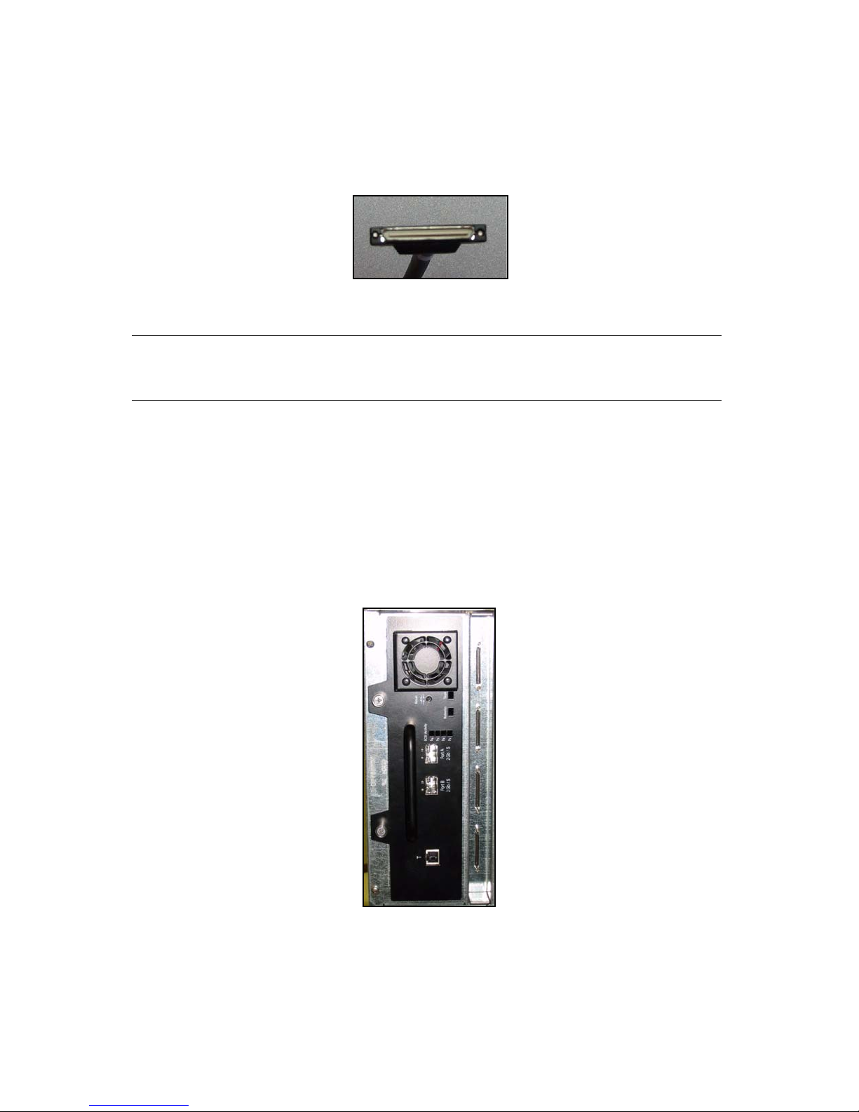
Cabling a Direct-Attach Drive
1. Use a SCSI cable to attach the drive directly to the host.
Figure 5-16 SCSI cable.
Caution: Make sure that the SCSI ID you chose for the drive does not
conflict with any SCSI IDs attached to the host.
Cabling the F-QIP
Once you have configured the library for an F-QIP and prepared it for operation, you
are ready to connect the library to a SAN or directly to a Fibre HBA.
Figure 5-17 The F-QIP in
the library.
61
Page 62

Chapter 5. Partitioning and Connecting to a Host
There are two Small Form-factor Pluggable ports per F-QIP on the rear panel to
connect the library to the host systems. The SFP ports are labeled Fibre Chnl A and
Fibre Chnl B.
The F-QIP provides two SFP ports on the rear panel, to connect the library to the host
systems. The different GBIC and SFP types and corresponding cables and connectors
are shown below.
Contact your Spectra Logic representative for more information or about converting to
a different connector type.
Cables and SFP Connectors
Figure 5-18 SCSI cable drive
to QIP.
Figure 5-19 Optical LC SFP. Figure 5-20 LC Optical
To attach the Fibre Channel cables:
1. Consult the documentation for your host operating systems and Fibre Channel
adapter cards for information on adding new devices. In particular, look for
details on creating and configuring device files or drivers, and whether your
system must be restarted before using new devices.
2. Make sure the QIPs are completely seated.
3. Insert the SFPs into the SFP ports on your library (and the host HBAs or switch
ports, if necessary).
Cable.
62
Page 63

6 Loading Media and More Configuration
The following sections describe steps involved in configuring the library:
• Importing Cartridges into the Library on page 63
• Configuring Library Users on page 65
• Configuring General Library Functions on page 68
• Configuring AutoSupport on page 72
Importing Cartridges into the Library
Use Bulk Load to put tapes into the library for the first time. Make sure you have all
your media ready.
Note: You can load tapes individually or using the TeraPack magazine.
To load cartridges from the Entry Exit (EE) port to a partition, follow these steps:
1. From the toolbar menu, select General > Import/Export. The Import/Export
Media screen appears.
2. From the Partition drop-down menu, select the partition into which the tapes
are to be imported. (Partition 1 is selected in Figure 6-1).
Figure 6-1 The Import/Export Media screen.
63
Page 64

Chapter 6. Loading Media and More Configuration
3. Select Bulk Load. A confirmation screen displays. Select Yes to confirm the
loading of media elements into the partition.
4. When the EE port opens, load media into the EE port and select Continue. The
library closes the EE port automatically. The media loads into the partition.
Repeat this procedure until all the media to be loaded has been loaded into the
partition.
Note: The number of slots available in the partition define the number of
cartridges you can import into it. To add more slots, select
Partition > Slots and Drives from the Configuration toolbar, or
order more slots using CoD at: www.SpectraLogic.com.
5. Once you are finished, select Stop Loading (Figure 6-2).
Figure 6-2 Feedback window for bulk loading media.
The Import Export Media screen (Figure 6-1 on page 63) again appears.
64
Page 65

Chapter 6. Loading Media and More Configuration
Figure 6-3 Security.
Configuring Library Users
Every library user is assigned to a group with its own set of
predefined library privileges. Refer to the definitions of the various
user types in Group Privileges/Security.
Use the Security toolbar (shown in Figure 6-3) to configure library
users; by assigning each user to one of the defined groups, you are
also setting up library security.
Review the following information about managing library users:
• Group Privileges/Security on page 65
• Adding a New User on page 66
• Editing an Existing User on page 67
• Deleting an Existing User on page 67
• Logging In as a Different User on page 67
Group Privileges/Security
Assign each library user to one of the three groups defined below. Each group has its
own set of privileges, also referred to as permissions. One default user per group is
initially configured. No password is required for any of the three default users until the
user name and password have been configured, as outlined in this chapter.
The superuser, with a default user name of su, is the initial login used to configure
other users and privileges.
To configure users, enter text using the keyboard icon.
Superuser Group Users assigned to the superuser group have total control of the library,
which includes defining other library users and their groups. The default user name in
this group is su. Note that the library requires at least one superuser for a library; you
are not allowed to delete the last member of the superuser group.
Administrator Group Users assigned to the administrator group control the library, but
cannot access the Library Users screen (Figure 6-4). The default user in this group is
administrator.
Operator Group Users assigned to the operator group can move, import, and export
media, but cannot gain access to more sensitive library operations such as
Configuration and Diagnostics. The default user in this group is operator.
65
Page 66

Chapter 6. Loading Media and More Configuration
Adding a New User
To add a new user, follow these steps.
1. Make sure that you are logged in as a member of the superuser group. If you are
not logged in as a member of the superuser group, select Security > Switch User;
then log in as a superuser.
2. From the toolbar menu, select Security > Edit Users. The Library Users screen
appears (Figure 6-4).
Figure 6-4 The Library Users screen.
3. Enter the user’s name in the User field.
4. Enter the user’s password in the Password field, then again in the Retype
Password field.
5. Select the User Type for the user.
Note: For definitions of user types, see Group Privileges/Security on
page 65.
6. Select Save. The user’s name and security setting displays in the list of users.
7. Repeat Step 3 through Step 6 for each library user.
66
Page 67

Chapter 6. Loading Media and More Configuration
Editing an Existing User
To change settings for an existing user, follow these steps.
1. Make sure that you are logged in as a superuser. If you are not logged in as a
superuser, select Security > Switch User; then log in as a superuser.
2. Select Security > Edit Users. The Library Users screen appears (Figure 6-4 on
page 66), showing a list of library user names.
3. Find the user’s name, then select Edit next to the name.
4. Change the user’s name, password, group, or any combination of these. When
you are finished, select Save.
Deleting an Existing User
To delete an existing user, follow these steps.
Note: You must always have one superuser; you cannot delete the last
superuser in the list of users.
1. Make sure that you are logged in as a superuser. If you are not logged in as a
superuser, select Security > Switch User; then log in as a superuser.
2. From the toolbar menu, select Security > Edit Users. The Library Users screen
appears (Figure 6-4 on page 66), showing a list of library user names.
3. Locate the name of the user to delete, then select Delete next to that user’s name.
4. A window asks you to confirm the deletion of that user; select OK. When the
screen refreshes, the user list no longer includes the user name you just deleted.
Logging In as a Different User
To log off as one user and log in as another, follow these steps.
1. From the toolbar menu, select Security > Switch User. The LC’s main login screen
appears (Figure 3-13 on page 31).
2. Type the name of the new user in the User field, and the user’s password in the
Password field.
3. Select Login. The library’s General Status screen appears, providing access to the
library functions permitted for this user.
67
Page 68

Chapter 6. Loading Media and More Configuration
Configuring General Library Functions
Use the Other Settings portion of the System Setup screen (Figure 6-5) to configure the
library’s system settings, described in the following sections:
• Library Name on page 68
• Refresh Rate on page 69
• Network Settings for Library Notifications and E-mail on page 69
• Mail Recipients on page 70
• Date and Time on page 72
• Configuring AutoSupport on page 72
Library Name
The library name is used to identify the library in library messages.
1. Make sure that you are logged in as a user in either the superuser or
administrator group.
2. Select Configuration > System. The System Setup screen appears (Figure 6-5).
Figure 6-5 The System Setup screen.
3. Enter the library name in the Library Name field, then select Save.
68
Page 69

Chapter 6. Loading Media and More Configuration
Refresh Rate
The refresh rate is the rate at which the LC regularly refreshes information for viewing
by the user. The default refresh rate is 60 seconds. To change the refresh rate for the
LC, follow these steps.
1. Under Other Settings in the System Setup screen (Figure 6-5), use the Refresh
drop-down menu to select a scheduled interval time.
2. Select Save.
Note: The LC can be refreshed as needed at any time by selecting the
refresh button located at the left end of the status bar (see Toolbars
on page 32).
Network Settings for Library Notifications and E-mail
Note: The LC automatically reboots when you save network settings.
By default, the library is configured to use Dynamic Host Configuration Protocol
(DHCP). Follow these steps to change or edit the network protocol.
1. From the System Setup screen (Figure 6-5 on page 68), select Edit next to
Network Settings; the Set Network Address screen appears (Figure 6-6).
Figure 6-6 The Set Network Address screen.
69
Page 70

Chapter 6. Loading Media and More Configuration
2. Determine which type of addressing the library network uses, then either:
•Select Static Address (highly recommended):
• Enter the static address in the Static Address field. Note that if you enter
this value while Static Address is not selected, the library ignores the value
and instead uses DHCP.
• Enter the subnet mask in the Subnet field.
• Enter the network gateway in the Gateway field.
•Select Save. The LC automatically reboots using the new settings.
•Select DHCP:
•Select Save. The LC automatically reboots using the new settings.
Note: If the LC does not reboot, it could be because no network cables
are attached to the library. Check that cables are attached, then
reset the LCM (see Resetting Components on page 110).
Mail Recipients
The library can send, to selected recipients, e-mail messages with system messages,
traces, and diagnostic results. Recipients can be set up to receive messages
automatically as they are generated by the library or ad hoc when traces are run.
Note: Network settings must be configured before mail settings; see
Network Settings for Library Notifications and E-mail on page 69.
70
Page 71

Chapter 6. Loading Media and More Configuration
To configure mail recipients, follow these steps.
1. From the System Setup screen (Figure 6-5 on page 68), select Edit next to Mail
Users. The Mail Recipients screen appears (Figure 6-7).
Figure 6-7 The Mail Recipients screen.
2. In the To field, enter the e-mail address of the party to receive messages. Be
sure to use the full address with the @ symbol, and do not use any spaces within
the e-mail address. To include multiple addresses, leave a space between each
alias.
Example: system.administrator@yourcompany.com
3. In the From field, enter a value, such as the name of the library; do not use any
spaces with the library designator.
Example: SpectraT120Library1
4. In the SMTP IP Address field, enter the IP address of your SMTP server, using
the standard IP format.
Example: 123.456.7.8
5. Select the type(s) of messages that the person in the To field should receive by
selecting one or more of the message types listed.
Note: Selecting message types automatically sends those messages to
the recipient as messages are generated by the library.
If no message type is selected, the recipient does not receive
messages automatically, but can be sent messages on an individual
basis when traces or diagnostics are run.
71
Page 72

Chapter 6. Loading Media and More Configuration
6. Select Save. The screen refreshes to show the mail recipient added in the
Recipients portion of the Mail Recipient screen (Figure 6-7 on page 71).
Select Previous to return to the System Setup screen.
Date and Time
The date and time set on the library is used only for library system messages; it is not
written to tape. To set the date and time displayed on the library, follow these steps.
1. From the System Setup screen (Figure 6-5 on page 68), use the Date and Time
drop-down menus to select the month, day (date), year, hour, and minute of the
hour to display.
2. Select Set Time.
Configuring AutoSupport
Before Using AutoSupport
Level 1 AutoSupport—included with your library purchase—automates the process of
telling SpectraGuard™ Support about a problem with your library. For each issue,
Technical Support creates an incident report, called a ticket, that tracks the issue
through to its resolution. When you open a ticket using AutoSupport, information is
automatically sent to SpectraGuard support staff. This information includes the library’s
serial number, site location, operating system, and software information, current
configuration, system logs, firmware information, and contact information for data
center staff.
Before you configure AutoSupport, make sure that the library has access to an e-mail
gateway, which is set up using the following:
• A 10BaseT/100BaseT Ethernet cable connected to the library through the LCM.
• AutoSupport (autosupport@spectralogic.com) must be set up as an e-mail recipient;
it is automatically added to your list of e-mail recipients when you enable the
AutoSupport option.
• A system setup that includes the library’s IP address, subnet, proxy server, etc.
If you have any questions, contact Spectra Logic Technical Support using the
information in Technical Support Contact Information on page 126.
Note: If you have RLC enabled, Spectra Logic recommends using it to
configure and use AutoSupport; this way you have full use of a
regular keyboard for the many text fields.
72
Page 73

Chapter 6. Loading Media and More Configuration
Creating AutoSupport Profiles
Follow these steps to create profiles for data center staff who attend to the library—
more specifically, for anyone assigned to work with SpectraGuard support staff to
troubleshoot problems.
1. Log in as a superuser.
2. Use the toolbar menu to select Maintenance > AutoSupport; the AutoSupport
Profiles screen appears (Figure 6-8).
Figure 6-8 The AutoSupport Profiles screen.
73
Page 74

Chapter 6. Loading Media and More Configuration
3. Select New Profile; the Company Information screen appears (Figure 6-9). In this
and all subsequent screens, shown here, make sure to fill out all required fields
noted by an asterisk.
Figure 6-9 The Company Information screen.
This completes creating a profile.
Figure 6-10 The AutoSupport Profiles screen.
To create another profile, repeat this process.
Note: When you create multiple profiles, they display in the order in
which they are created, not alphabetically or numerically.
74
Page 75

Chapter 6. Loading Media and More Configuration
Editing AutoSupport Profiles
Follow these steps to edit profiles that you have already created.
1. Log in as a superuser.
2. Use the toolbar menu to select Maintenance > AutoSupport; the AutoSupport
Profiles screen appears (Figure 6-10).
3. Select Edit Profile corresponding to the contact you want to edit; the Company
Information screen appears.
4. Edit information in that screen as necessary, then select Next; the Contact
Information screen appears.
5. Edit information in that screen as necessary, then select Next; the System and
Mail Information screen appears.
6. Edit information in that screen as necessary, then select Next; the Save Profiles
screen appears.
7. Verify that the information you changed has been updated.
8. Select Save; the AutoSupport profiles screen appears, displaying the updated
profile.
Deleting AutoSupport Profiles
Follow these steps to delete profiles that you have already created.
1. Log in as a superuser.
2. Use the toolbar menu to select Maintenance > AutoSupport; the AutoSupport
Profiles screen appears (Figure 6-10)
3. Select Remove corresponding to the contact you want to delete; the Remove
Profiles screen appears, asking you to confirm the deletion.
4. Select Remove; the AutoSupport profiles screen appears, no longer displaying
the profile you deleted.
75
Page 76

Chapter 6. Loading Media and More Configuration
76
Page 77

Chapter 7. Using the Library
7 Using the Library
This chapter reviews using the library, including overviews and best practices:
• Library Controller Overview, below
• Best Practices: Logging On and Off on page 78
• Best Practices: Media Handling on page 80
• Displaying Inventory on page 80
• Importing and Exporting Media on page 82
Library Controller Overview
Use the Library Controller (LC) to perform the library tasks reviewed in this chapter,
including logging in, importing and exporting media, and checking messages.
For more detailed information on how to use the LC, see Interpreting the Library
Controller on page 32.
Entering Information
To enter information requested by the LC, you need access to a keyboard. You can use
either of the following keyboard types.
Soft Keyboard
Bring up the LC’s soft keyboard by selecting the keyboard icon (Figure 7-1) in the
lower right corner of the front panel.
Note: The front panel keyboard’s backspace key erases only a single
preceding character, even if multiple characters are highlighted.
Figure 7-1 The keyboard icon.
77
Page 78
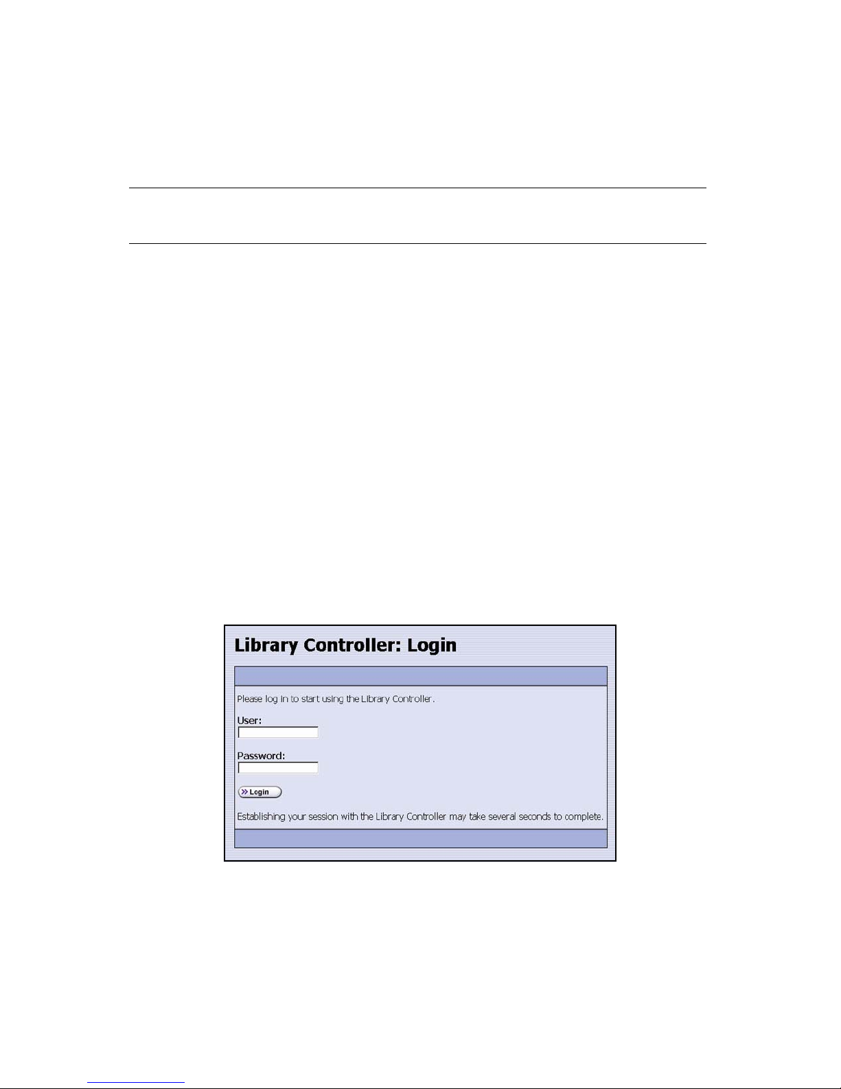
Chapter 7. Using the Library
RLC
Use the optional Remote Library Controller (RLC) to manage the library from your
computer and using your computer keyboard.
Note: You cannot use the RLC until after the library is initially configured
with an IP address.
For security reasons, some functions work only through the LC and not the RLC. For
example, physically importing or exporting media requires the user to be in front of
the library itself; therefore, the user must handle these operations using the LC.
Best Practices: Logging On and Off
Log on to the library using your assigned user name and password. Any library user in
any group—superuser, administrator, or operator—can use the Library Controller (LC)
to perform the functions described in this chapter.
Logging On
In the main login screen, enter your user name and password, then select Login.
Figure 7-2 The LC’s main login screen.
78
Page 79
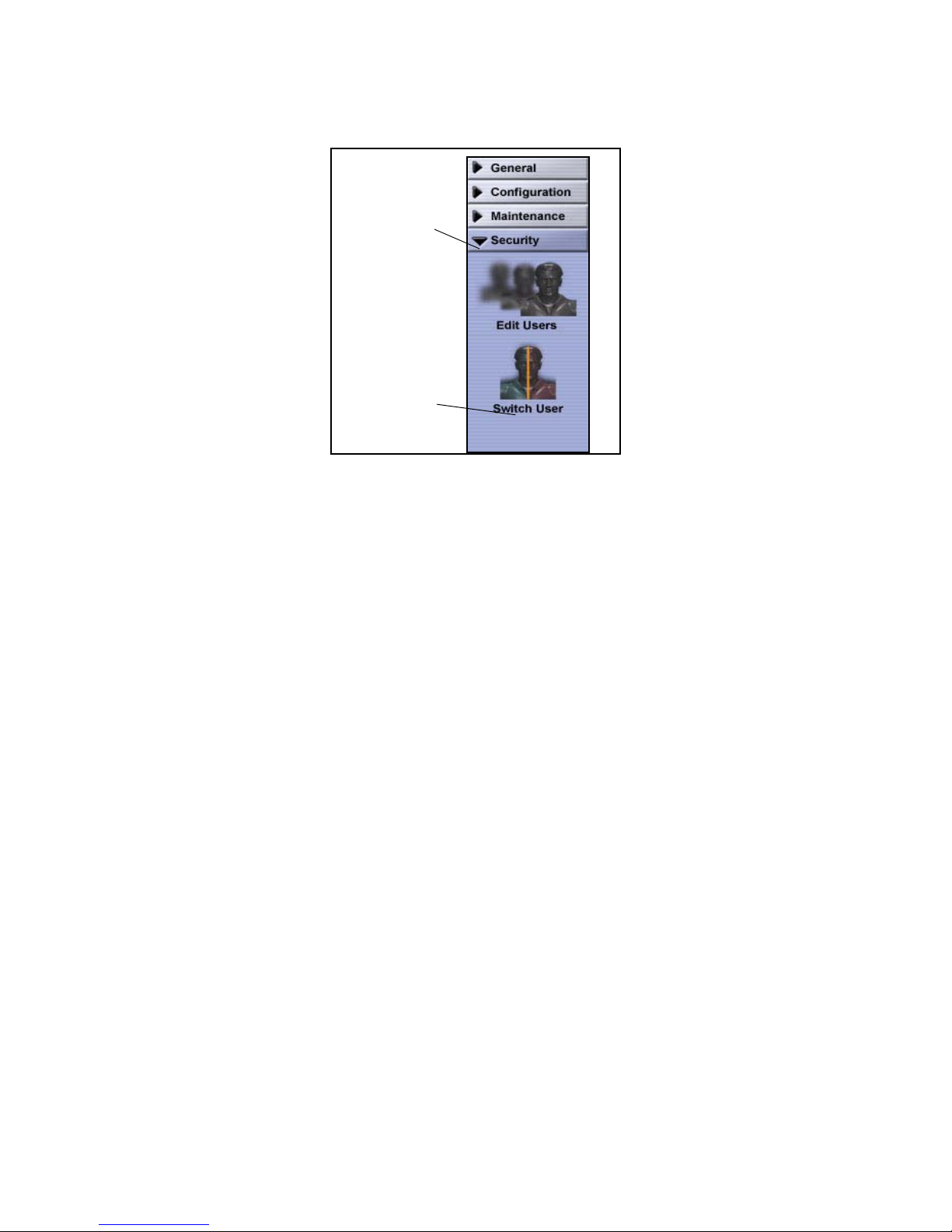
Chapter 7. Using the Library
Select Security
from the tool bar.
Two icons display:
Edit Users and
Switch User.
Select Switch
User to display
the login screen.
If a screen other than Login displays, select Security > Switch User (Figure 7-3).
Figure 7-3 The Security toolbar.
After logging on, check the General Status screen to get an update on library status.
Logging Off
When you finish using the library, select Switch User to log off. Logging off causes the
login screen to display.
79
Page 80
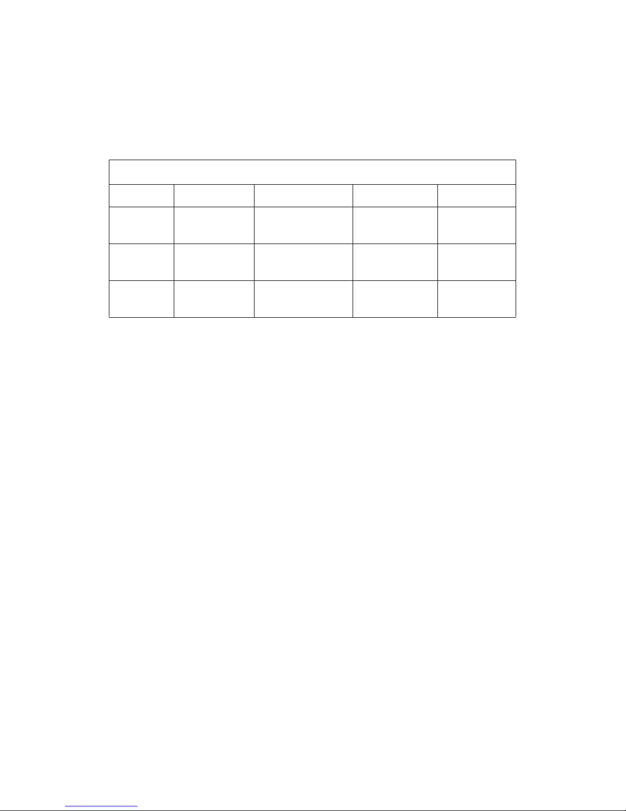
Chapter 7. Using the Library
Best Practices: Media Handling
1. Make sure that media is stored in the following conditions; these conditions are
also maintained within the Spectra T120 library.
Environmental Requirements for Media
a
Factor
Temperature +50°F to +113°F
Relative
Humidity
Wet Bulb
Temperature
a. All specifications are subject to change without notice.
b. The upper limit applies to the drive, not the library. Be sure there is adequate air flow around library at all times.
2. Use only approved media in the library. For a list of approved media, see Media
and Media Accessories on page 119.
3. Read these other sections, which review the following media handling tasks:
• Displaying Inventory on page 80
• Bulk Loading on page 83
• Bulk Unloading on page 85
• Loading Single Tapes on page 86
Operating
(+10°C to +45°C)
10% - 80% 20% - 80% 20% - 50% 5% - 80%
+79°F (+26°C) +79°F (+26°C) +79°F (+26°C) +79°F (+26°C)
b
Operational Storage Archival Storage Shipping
+61°F to +90°F
(+16°C to +32°C)
+61°F to +77°F
(+16°C to +25°C)
-9°F to +120°F
(-23°C to +49°C)
• Unloading Single Tapes on page 89
Displaying Inventory
Use the Inventory screen to display inventory, and also to select and move specific
media elements.
To view a partition’s inventory, follow these steps.
1. From the toolbar menu, select General > Inventory. The Inventory screen
appears (Figure 7-4 on page 81).
80
Page 81

Chapter 7. Using the Library
2. Select the partition with the inventory you want to display from the Partition
drop-down menu, then select Go. (Partition 1 is selected in Figure 7-4.)
Figure 7-4 The Inventory screen.
3. Select from the Source drop-down menu (called out in Figure 7-5) the type of
inventory to display—storage media, entry/exit media, media in drives, or all
media—then select Go.
Figure 7-5 The Source drop-down menu.
The Source window displays the requested media inventory.
81
Page 82

Chapter 7. Using the Library
Importing and Exporting Media
Caution: Do not manually insert media into drives. SAIT drives calculate
incoming force when a tape is inserted, then eject the tape with
matching force. A manually fed tape may be ejected with extra
force, which may damage robotics.
Vorsicht: Führen Sie Datenträger nicht manuell in Laufwerke ein. SAIT
Laufwerke messen die Kraft, mit der eine Datencartridge
eingeführt wird und geben die Datenträger mit der gleichen
Kraft aus. Eine manuell eingelegte Cartridge kann mit einer zu
großen Kraft ausgegeben werden und zur Beschädigung der
Robotik führen.
You can import and export media into or out of a partition using the EE port located
on the front of the library (Figure 7-6).
Note: A partition must be created before you can import media.
• If you have multiple cartridges to import, use Bulk Loading. Go to Bulk Loading on
page 83.
• If you have multiple cartridges to export, use Bulk Unloading. Go to Bulk
Unloading on page 85.
• To import media tapes one at a time, go to Loading Single Tapes on page 86.
• To export media tapes one at a time go to Unloading Single Tapes on page 89.
Figure 7-6 The EE port.
82
Page 83

Chapter 7. Using the Library
Bulk Loading
Use a bulk load when loading several tapes into a partition. When performing a bulk
load, the library robotics loads media tapes, starting with the cartridge in Slot 1 of the
EE port to the first available slot in the partition you select. Slot 2 of the EE port is
loaded into the next available slot in the partition, and so on, until all the slots of the
EE port are emptied.
Note: If your media is bar coded sequentially, you may want to load the
media tapes sequentially as well.
You may also replace the EE port’s TeraPack case with a TeraPack
case that is fully loaded with media, to load tapes more quickly.
To load several media cartridges from the EE port to a partition, follow these steps:
1. Logically sort the media to be to be imported, if necessary.
2. From the toolbar menu, select General > Import/Export. The Import/Export
Media screen appears.
3. From the Partition drop-down menu, select the partition into which the tapes
are to be imported, and select Go. (Partition 1 is selected in Figure 7-7).
Figure 7-7 The Import/Export Media screen.
4. Select Bulk Load.
83
Page 84

Chapter 7. Using the Library
5. A confirmation screen appears. Select Yes to confirm the loading of media
elements into the partition.
6. When the screen prompts you, load media into the EE port and select Continue.
The media is loaded into the partition. Repeat this procedure until all the
desired media has been loaded into the partition.
Note: You can only load as much media as there are slots available in the
partition. To add more slots, select Configuration > Partition > Slots
and Drives from the Configuration toolbar. If all slots are used, you
will need to add capacity using the CoD feature described in
Capacity on page 16.
7. Once you are finished, select Stop Loading (Figure 7-8).
Figure 7-8 Feedback window for bulk loading media.
The Import/Export Media screen appears.
84
Page 85

Chapter 7. Using the Library
Bulk Unloading
1. Select General > Import/Export. The Import/Export Media screen appears.
2. From the Partition drop-down menu, select the partition from which you are
exporting the media and select Go (Figure 7-9.)
Figure 7-9 The Import/Export Media screen.
3. Select Bulk Unload.
4. A feedback screen appears asking for confirmation. Select Yes. The library
begins to unload all the media from that partition into the EE port.
5. When the library prompts you, remove all media from the EE port.
Note: For faster removal, unload the entire EE port’s TeraPack case and
place an empty TeraPack case in its place.
Select Continue to continue unloading media from the partition.
85
Page 86

Chapter 7. Using the Library
6. Once all of the media tapes have been removed from the library, the LC prompts
you to empty the EE port and select Finished (Figure 7-10).
Figure 7-10 Feedback Required screen for bulk unloading.
The Import/Export Media screen appears.
Loading Single Tapes
To import a single piece of media or just a few tapes into a partition, follow these
steps:
1. Select General > Import Export. The Import/Export Media Screen appears.
86
Page 87

Chapter 7. Using the Library
2. Use the drop-down menu to select the partition you want to load the tape into
and select Go. (Partition 1 is selected in Figure 7-11.)
Figure 7-11 The Import/Export Media screen.
3. Select Open EE Port. The library EE port opens.
4. Insert the tapes into one or more empty EE port slot.
5. Select Close EE Port. The EE port closes and the library robotics scans the EE
port for new media.
6. Next, select Inventory from the General toolbar. The Inventory screen appears
(Figure 7-12 on page 88).
87
Page 88

Chapter 7. Using the Library
7. From the partition drop-down menu select the partition you want to import the
media into and select Go. (Partition 1 is selected in Figure 7-12.)
Figure 7-12 The Inventory screen.
8. To import the media, select Entry/Exit from the Source drop down menu and
select Go.
9. Select Storage from the Destination drop-down menu and select Go.
10. Next, in the Source list, highlight the tape that you just inserted and highlight
the storage slot where you want the tape to be placed.
11. Select Add Move to add the move to the queue.
Note: You can queue multiple moves then select Start Moves at your
discretion.
12. When you are ready to start the move, select Start Moves.
13. Once the media tape is moved to that location, a Move Status screen appears
stating the success of the move operation.
88
Page 89
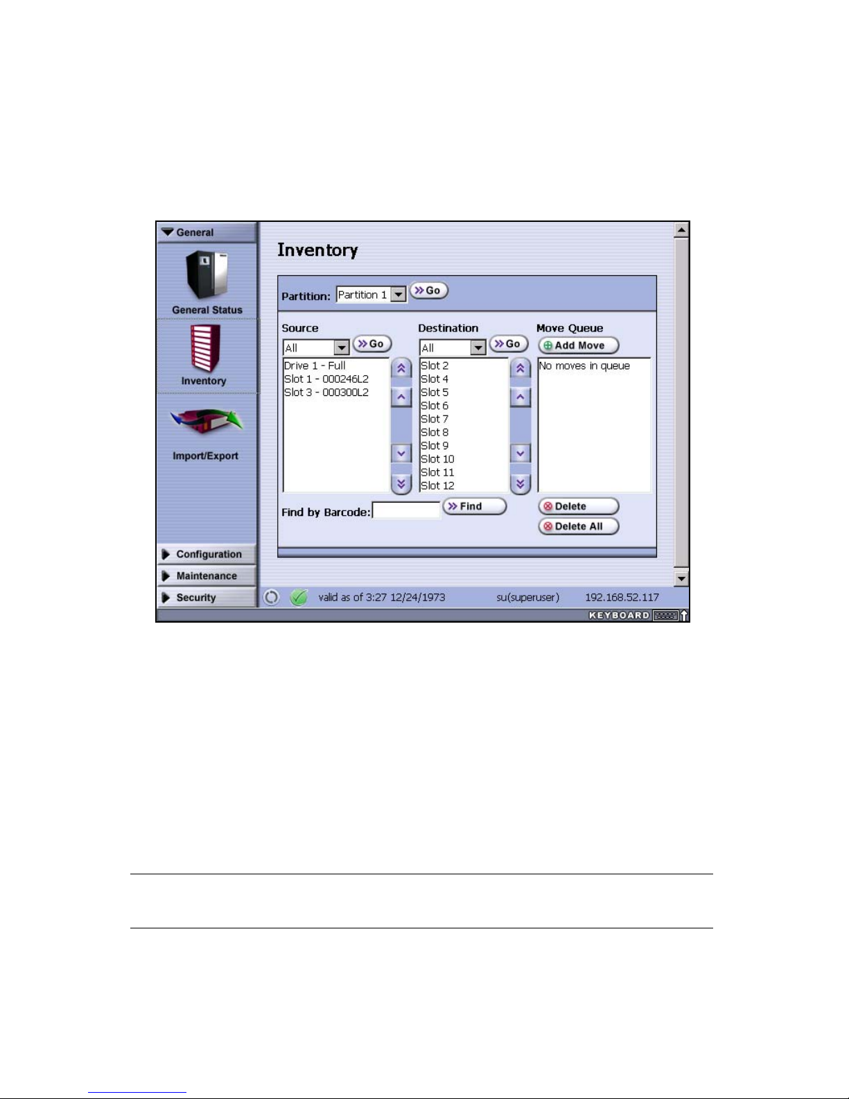
Chapter 7. Using the Library
Unloading Single Tapes
1. Select General > Inventory. The Inventory Screen appears.
2. Use the partition drop-down menu to select the partition from where you want
to export the tape from and then select Go. (Partition 1 is selected in).
Figure 7-13 The Inventory screen.
3. To export the tape, select Storage from the Source drop-down menu and select
Go. All the available media elements in Storage Slots are identified in the Source
list.
4. Select Entry/Exit from the Destination drop-down menu and select Go. All the
media slots available in the EE port are identified in the Destination list.
5. Highlight the specific tape in the Source list and then highlight the slot in the EE
port where you want the tape to be placed.
6. Select Add Move to add the move to the queue.
Note: You can queue multiple moves then select Start Moves at your
discretion.
7. Select Start Moves when you are ready to remove the tape; it is moved to the EE
port slot and a Move Status screen appears stating that the move was successful.
89
Page 90

Chapter 7. Using the Library
8. Select Import/Export from the General Toolbar. The Import/Export Media screen
appears (Figure 7-14).
Figure 7-14 The Import Export Media screen.
9. Select Open EE Port. The library EE port opens.
10. Remove the tape from the EE port, then select Close EE Port.
90
Page 91

8 Maintaining the Library
Messages Time of last refresh
Current user User’s group
Refresh
Library’s IP address (or name)
This chapter describes recommended tasks for maintaining the Spectra T120 library
and its tape drives. It reviews procedures for regular maintenance and troubleshooting,
including:
• Tips on Getting Library Information Quickly, below
• Cleaning Drives on page 93
• Replacing the Air Filter on page 93
• Library Firmware Packages on page 95
• Firmware Package Support on page 95
• Updating Drive Firmware on page 103
Tips on Getting Library Information Quickly
The quickest way to obtain important library information is to check the LC’s status
bar.
Status Bar
In addition to providing a screen refresh button, the status bar (Figure 8-1) at the
bottom of the LC provides the following information:
• Whether there are any system messages
• When the screen was last refreshed
• The library’s IP address (on the LC) or library name (on the RLC)
• The currently logged-in user and the group to which the user belongs
Figure 8-1 The status bar as it is seen on the LC.
91
Page 92

Chapter 8. Maintaining the Library
Messages
The Messages icon shows the status of library components, using these designations:
Symbol Meaning
i in blue: Check messages for information.
Check mark in green: Component is functioning correctly.
Exclamation point in yellow: Check messages for component status.
X in red: Check messages for component error.
Last Refresh
The date and time shown after Valid as of indicates the last time that the screen
refreshed. The screen can be set to refresh at designated intervals, or the user can
refresh it as needed by selecting the refresh button on the status bar.
IP Address or Name
If you are using the LC, the library’s IP address is displayed on the status bar.
If you are using the RLC, the library’s name is shown in place of the library’s IP
address. To find the library’s IP address using the RLC, follow these steps:
1. Use the Toolbar menu to select Configuration > System; the System Setup screen
appears.
2. On the bottom part of that screen, select Edit next to Network Settings; the Set
Network Address screen appears (Figure 6-6 on page 69), displaying the IP
address for the library.
User and Group
The status bar shows the name of the user currently logged in, and, next to it in
parentheses, the user’s security group (see User Security on page 14).
92
Page 93

Chapter 8. Maintaining the Library
Cleaning Drives
Use your backup software to clean the library’s drives when a drive indicates that it
needs cleaning, as outlined in LTO-2 Drive Cleaning Notification on page 116.
Use only certified cleaning cartridges to clean your tape drives. For information on
ordering these cartridges, see How To Order on page 121.
Replacing the Air Filter
The library air filter catches contaminants as the fans pull cool air into the library. A
clogged air filter can cause operational problems due to excessive temperatures inside
the library.
You may want to inspect the filter at least once every three months for preventive
maintenance. If the air filter is clogged, replace it immediately.
Caution: Some environments may require more frequent filter inspection
and replacement. If an air filter gets clogged quickly, consider
moving the library to a more dust-free location or improve the
environment where it is located.
Vorsicht:In bestimmten Umgebungen kann es notwendig sein, Filter öfter
zu prüfen und auszutauschen. Falls Filter sehr häufig gewechselt
werden müssen kann es sinnvoll sein, die Library in einer
weniger staubigen Umgebung zu installieren oder die
Umgebungsbedingungen zu verbessern.
After replacing the filter, clean all tape drives. Use your backup software to perform
the drive cleaning operation.
To order replacement filters, contact your sales representative; see Contacting Spectra
Logic Sales on page 123.
93
Page 94

Chapter 8. Maintaining the Library
Replace the Filter
1. Remove the fan filter cover (Figure 8-2) by removing the top screw with a #2
screwdriver.
Figure 8-2 The fan filter cover.
2. Remove the old air filter from the library (Figure 8-3).
Figure 8-3 The filter.
3. Place the new air filter on the screen.
4. Re-attach the screen.
94
Page 95

Chapter 8. Maintaining the Library
Library Firmware Packages
Firmware packages are groupings of program code that update the library and its
components.
This section covers the following information:
• Firmware Package Support, below
• Reviewing Current Firmware Package Levels on page 96
• Updating Firmware Packages on page 96
• Managing Firmware Packages on page 100
Note: You must have a valid service agreement with Spectra Logic
Technical Support in order to upgrade library firmware packages.
For more information, refer to Service and Support on page 125.
Firmware Package Support
Spectra Logic provides complete support for the most currently shipped releases of
firmware packages. Customers using previously released firmware packages are asked
to upgrade to the current release.
95
Page 96

Chapter 8. Maintaining the Library
Reviewing Current Firmware Package Levels
Follow these steps to identify the current firmware package versions used by the
library’s hardware.
1. Select Maintenance > Package Update. The Package Update screen appears
(Figure 8-4).
Figure 8-4 The Package Update screen.
2. Compare your library’s current package level to the latest firmware package
available for the library on the Spectra Logic Web site.
i. Go to www.SpectraLogic.com.
ii. Select Support > Firmware & Drivers > Library Firmware.
iii. To update, see Updating Firmware Packages on page 96.
Updating Firmware Packages
Note: To access and upgrade the library with the latest firmware
package, you must have a current service agreement with Spectra
Logic Technical Support. If you have questions about your service
agreement, contact Technical Support as described on page 125.
1. Wait until all backup processes have completed before updating library
firmware.
2. Get a copy of the firmware package through a direct connection to the Spectra
Logic Web site or from a local firmware server (described in Setting Up
Firmware Package Servers on page 101). If you use either of these methods,
proceed to Software Installation on page 97.
Alternately, you may use a USB device containing the firmware package
upgrade. If you update using a USB device, proceed to the next step.
96
Page 97

Chapter 8. Maintaining the Library
3. If you are using a USB device, insert the USB device into the LCM, and then
proceed to Software Installation.
Software Installation
To update the library’s firmware, follow these steps.
1. Use the LC’s toolbar menu to select Maintenance > Package Update. The Package
Update screen appears (Figure 8-5).
Figure 8-5 The Package Update screen.
2. Select Begin Package Update. The License Agreement screen displays.
3. Read this agreement, then select Accept or Decline. If you select Accept, the
Select Package Source screen appears (Figure 8-6).
Figure 8-6 The Select Package Source screen.
97
Page 98

Chapter 8. Maintaining the Library
4. Select an available firmware package source:
•Select Local for packages on your own server.
•Select USB Key for packages available on a USB device. Make sure that the
USB device is inserted correctly in the back of the library. Note that there is a
brief delay while the library recognizes the USB device.
•Select Spectra Logic to download a package from Spectra Logic’s server. Note
that this option is only available if the library has a configured Web
connection.
5. Select Next. The Select Package screen appears (Figure 8-7).
Figure 8-7 The Select Package screen.
6. Select the firmware package to update.
Note: You may only update one firmware package at a time.
7. Select View Release Notes to display detailed information about the package you
have selected.
8. After reviewing the release notes, select Previous to return to the Select Package
screen, or Next to display the Package Details screen (Figure 8-8).
98
Page 99

Chapter 8. Maintaining the Library
9. Read the information on the Package Details screen (Figure 8-8 on page 99) to
understand which components are affected by the upgrade and how.
Figure 8-8 The Package Details screen.
10. Select Update; a progress screen appears. When completed, the Package Results
screen appears, showing that the update completed successfully.
Note: If the firmware package update affects LCM files, the LCM reboots
after the update.
If you are using the RLC to update the library, the RLC screen does
not refresh when the LCM reboots. Wait until the library (LCM)
initializes, then re-enter the library’s IP address in a Web browser.
99
Page 100

Chapter 8. Maintaining the Library
Managing Firmware Packages
Newly updated firmware packages reside on the LCM. Eventually, you may have
multiple prior firmware packages (one per update). The library may prompt you to
remove them in a rare circumstance, or you may choose to remove them at some point.
Remove them using the LC or RLC after the most recent package has been saved to the
library and installed. Deleting firmware files does not delete any firmware packages
from library components; it simply removes the firmware files from local storage on
the LCM.
Note: Packages are normally accessed in the Select Package Source
screen (Figure 8-6 on page 97) as the Local option. Make sure
before deleting that you no longer need access to these files.
To delete firmware files from the LCM, follow these steps.
1. Select Maintenance > Package Update. The Package Update screen appears
(Figure 8-9).
Figure 8-9 The Package Update screen.
100
 Loading...